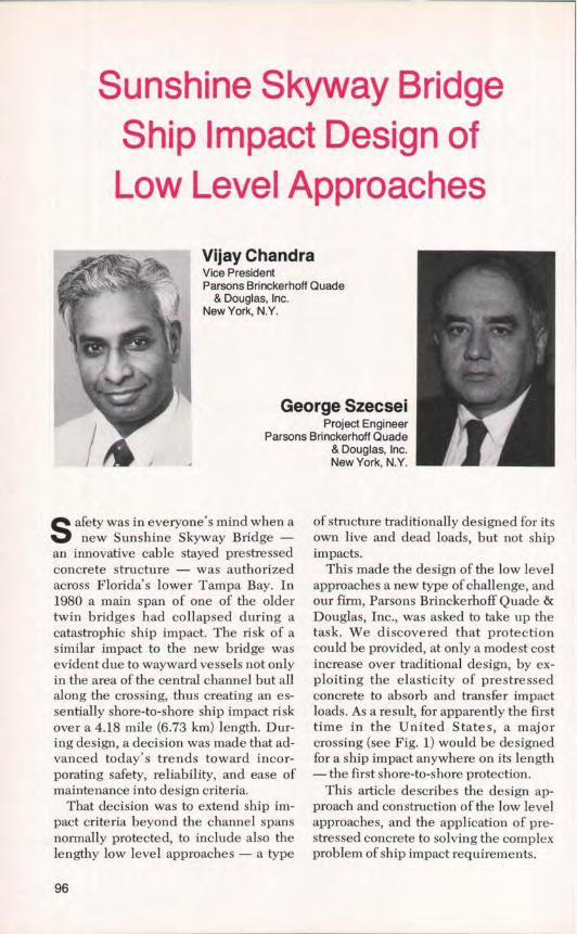
Sunshine Skyway Bridge Ship Impact Design of Low Level Approaches Vijay Chandra Vice President Parsons Brinckerhoff Quade & Douglas, Inc. New York, N.Y. George Szecsei Project Engineer Parsons Brinckerhoff Quade & Douglas, Inc. New York, N.Y. S afety was in everyone's mind when a new Sunshine Skyway Bridge - an innovative cable stayed prestressed concrete structure — was authorized across Florida's lower Tampa Bay. In 1980 a main span of one of the older twin bridges had collapsed during a catastrophic ship impact. The risk of a similar impact to the new bridge was evident due to wayward vessels not only in the area of the central channel but all along the crossing, thus creating an es- sentially shore-to-shore ship impact risk over a 4.18 mile (6.73 km) length. Dur- ing design, a decision was made that ad- vanced today's trends toward incor- porating safety, reliability, and ease of maintenance into design criteria. That decision was to extend ship im- pact criteria beyond the channel spans normally protected, to include also the lengthy low level approaches — a type of structure traditionally designed for its own live and dead loads, but not ship impacts. This made the design of the low level approaches a new type of challenge, and our firm, Parsons Brinckerhoff Quade & Douglas, Inc., was asked to take up the task. We discovered that protection could be provided, at only a modest cost increase over traditional design, by ex- ploiting the elasticity of prestressed concrete to absorb and transfer impact loads. As a result, for apparently the first time in the United States, a major crossing (see Fig. 1) would be designed for a ship impact anywhere on its length —the first shore-to-shore protection. This article describes the design ap- proach and construction of the low level approaches, and the application of pre- stressed concrete to solving the complex problem of ship impact requirements. 96
Parsons Brinckerhoff Quade& Douglas, Inc.New York, N.Y.
S afety was in everyone's mind when anew Sunshine Skyway Bridge -
an innovative cable stayed prestressedconcrete structure — was authorizedacross Florida's lower Tampa Bay. In1980 a main span of one of the oldertwin bridges had collapsed during acatastrophic ship impact. The risk of asimilar impact to the new bridge wasevident due to wayward vessels not onlyin the area of the central channel but allalong the crossing, thus creating an es-sentially shore-to-shore ship impact riskover a 4.18 mile (6.73 km) length. Dur-ing design, a decision was made that ad-vanced today's trends toward incor-porating safety, reliability, and ease ofmaintenance into design criteria.
That decision was to extend ship im-pact criteria beyond the channel spansnormally protected, to include also thelengthy low level approaches — a type
of structure traditionally designed for itsown live and dead loads, but not shipimpacts.
This made the design of the low levelapproaches a new type of challenge, andour firm, Parsons Brinckerhoff Quade &Douglas, Inc., was asked to take up thetask. We discovered that protectioncould be provided, at only a modest costincrease over traditional design, by ex-ploiting the elasticity of prestressedconcrete to absorb and transfer impactloads. As a result, for apparently the firsttime in the United States, a majorcrossing (see Fig. 1) would be designedfor a ship impact anywhere on its length—the first shore-to-shore protection.
This article describes the design ap-proach and construction of the low levelapproaches, and the application of pre-stressed concrete to solving the complexproblem of ship impact requirements.
96
Presents the design-construction method used forthe low level approaches together with theapplication of prestressed concrete in solving theunprecedented shore-to-shore ship impactrequirements of the Sunshine Skyway Bridge. Theresults show that prestressed concrete is anexcellent material for resisting impact.
THE NEEDIn 1980 the phosphate freighter
Summit Venture struck the southbound(western) bridge of the Sunshine Sky-way, causing a widely publicized failureand creating the need for the new Sun-shine Skyway Bridge.
Before the impact, the crossing con-
sisted of twin two-lane bridges with bal-anced cantilever truss main spans. Theoriginal of the pair, designed by ParsonsBrinckerhoff in 1954, had been atrendsetter in its day: the most massiveapplication yet of prestressed concretefor an American bridge. Originally atwo-way bridge, it had been convertedin 1971 to northbound-only to share the
Fig. 1. A finished view of the new bridge with old bridges in the background. This is thefirst time a major crossing has been designed for ship impact along its entire span.
LOW LEVEL APPROACH HIGH LEVEL MAIN SPAN AREA HIGH LEVEL LOW LEVEL APPROACHAPPROACH APPROACH
TWIN STRUCTURE SINGLE STRUCTURE TWIN STRUCTURE
NOTE: I fool • 30.48 cm
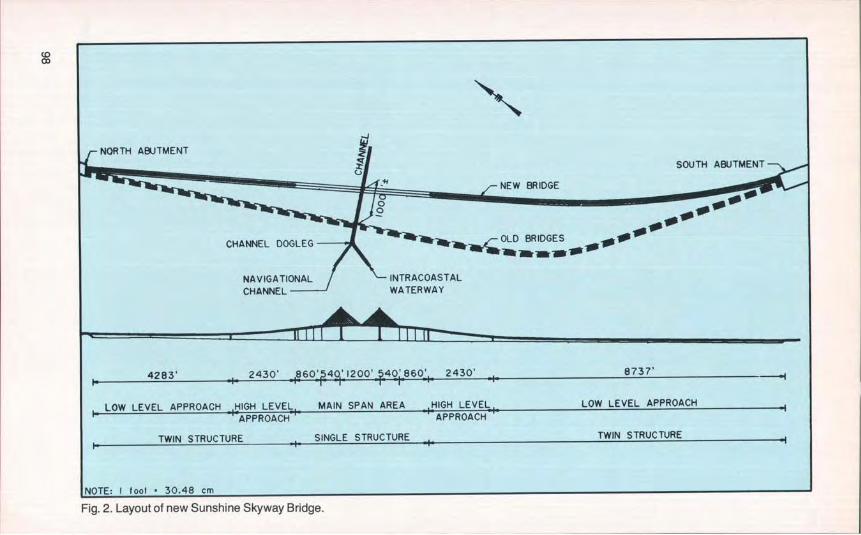
Fig. 2. Layout of new Sunshine Skyway Bridge.
traffic with its newer twin; it was this1971 bridge that was struck by theSummit Venture, decommissioning thesouthbound crossing, reducing thefour-lane total to two, and disrupting thelocal economy and commuters. Theoriginal 1954 crossing was undamaged,and again carried traffic in both direc-tions during construction of the newcable stayed bridge. Both older bridgeswill eventually be demolished, withsections perhaps left (depending on theoutcome of current studies) for a newlife as fishing and recreational piers.
Fig. 1 shows the new cable stayedSunshine Skyway crossing in its fin-ished state, with the two older trusscrossings in the background. Thus thenew crossing, opened to traffic in mid-1988, was born not only to replace theprevious crossings and improve the re-gional economy, but to provide an im-proved, safer structure — better aligned,more generous in navigational clear-ances, and with new criteria to resist theimpact forces of any aberrant marinetraffic. With its striking cable stayedmain span designed by Figg and MullerEngineers and its lengthy low level ap-proaches designed by ParsonsBrinckerhoff, this new 4.18 mile (6.73km) crossing with shore-to-shore shipimpact protection is at the forefront oftoday's prestressed concrete bridges.
THE NEW, SAFER BRIDGE
The new bridge provided superioradvantages in the form of better align-ment, greater clearances and more effi-cient structural configuration.
Better AlignmentSafety planning began at the most
basic level: where to place the bridge.There is a dogleg in the Tampa BayChannel west of the bridge where theIntracoastal Waterway Channel meetsthe Tampa Bay Channel. By putting thenew bridge 1000 ft (304.8 m) farther east
than the old, the skew to the channelcould be reduced and more space pro-vided between bridge and dogleg. Thisarrangement offered better maneuver-ability to ship captains trying, some-times in inclement weather, to navigatethe dogleg in the channel and then gettheir ships properly aligned beforepassing between the bridge piers. Thisrealignment supplements the impactprotection built into the new design (seeFig. 2).
Greater ClearancesBy nearly all measures, the new
bridge is larger than either of its twinpredecessors and gives ships greaterclearance. For the record, some of theparticulars of the new bridge are:• Total length of crossing = 21,880 ft
ways): north = 4283 ft (1.31 km)each; south = 8737 ft (2.66 km)each
High level approaches (twin road-ways): north and south = 2430 ft(0.74 km) each
Main span area (single wide road-way): 4000 ft (1.22 km)(Cable stayed spans = 540-1200-540 ft) (165-366-165 m)
• Main channel width = 500 ft (152 m)• Main span horizontal clearance = 350
ft (106.7 m) on either side of chan-nel [versus 182 ft (55.5 m) in the oldbridges]
• Vertical clearance:Over the channel = 175 ft± (53.3 m)At low level approaches = 20 ft ± (6.1
m)• Water depth:
Low level approaches = 0 to 24 ft (0to 7.3 m), mostly 12 to 24 ft (3.7 to7.3 m)
High level approaches = 24 to 30 ft(7.3 to 9.1 m)
Main span area = 30 ft (9.1 m)Channel = 43 ft (13.1 m)
• Tides:
PCI JOURNAL/July-August 1988 99
Tidal range: mean = 1.3 ft (40 cm);extreme = 3.8 ft (116 cm).
Current: 0.8 to 1.0 knot (1.48 to 1.85km per hr); 3.0 knots (5.56 km perhr) possible in outgoing tidalstream.
• Wind = 50 knots (92.66 km per hr) ormore, 65 knots (120.46 km per hr)maximum recorded.
Hurricane possible every other yearwithin 60 nautical miles (111.19km).
Structural ConfigurationFrom shore to shore, the new bridge
complex consists of three distinct typesof prestresssed concrete structures, eachwith appropriate considerations for im-pact risk assessment and protection. Thedual roadway structures of the low levelnorth and south approaches stretch fromthe shores, rising into high level ap-proaches that lead in turn to the mainspan area. In the main span area, theparallel approach roadways merge into asingle wide roadway with a centralcable stayed main span and two flankingspans (see Fig. 2). These are thecharacteristics of the structural types:
• Low level north and south ap-proaches. These consist of twoparallel two-lane structures, one fornorthbound and the other forsouthbound. The superstructureconsists of a four-span continuousreinforced concrete deck slab sup-ported on precast prestressed con-crete AASHTO Type IV girders.The substructure consists of rein-forced concrete wall type piersfounded on 20 in. (51 cm) squareprecast prestressed concrete piles.The length of each span is ap-proximately 100 ft (30.5 m). Thepiers of the parallel roadways areconnected across between the twostructures by precast prestressedconcrete frangible struts.
• High level north and south ap-proaches. These also consist of two
parallel two-lane structures, one fornorthbound and the other forsouthbound traffic. Single cell,precast post-tensioned, continuousconcrete box girders, supported onconcrete piers, are used. Thelength of each span is 135 ft (41.2m). The foundations are supportedby 24 in. (61 cm) square, precastprestressed concrete piles.
• Main span area. This consists of asingle structure with a single cell,precast post-tensioned, concretebox superstructure that carriesnorthbound and southbound traf-fic. The substructure consists ofpost-tensioned concrete piers sup-ported by 24 in. (61 cm) squareprecast prestressed concrete piles.The main piers support 432 ft high(131.7 m) cable stayed pylons. Themain and flanking spans are cablestayed, with a single plane of staysat the center of the two roadways.
COLLISION RISK
The risk assessment and impactcriteria are now discussed.
Risk AssessmentAt the initial stage of the project, the
Florida Department of Transportation(FDOT), through Figg and Muller En-gineers, requested COWlconsult ofDenmark to perform a ship collision riskassessment study. The study is based ona mathematical risk assessment model,using available background data. Thestudy considers the various types of ma-rine traffic using lower Tampa Bay andidentifies the main reasons for ship col-lisions with bridges:
• Alignment of the bridge with re-spect to the entrance channel
The report stated that the designerscould use probability to optimize safetyand cost by distributing the risk levelalong the bridge structure and by ac-cepting a tolerable level of risk. Thefollowing practical protective measureswere suggested:
• Design the piers and pier shaftsalong the entire length for certainmagnitudes of static ship impactforce since superstructures them-selves rarely have a substantial re-sistance to horizontal loads. Thepoint of impact should correspondto the height of the hull of relevantships.
• Raise the roadway level along theentire crossing.
• Protect the main and flanking pierswith sand-filled rock islands andwith dolphins.
• Shift the alignment farther east toincrease the distance from the 18degree dogleg in the navigationchannel west of the old bridges.
• Consider aberrant barges as themost likely vessels to hit thebridges.
Impact CriteriaAs a result of the ship collision risk
assessment study, FDOT set up the fol-lowing criteria for the design of the newSunshine Skyway Bridge, in addition toAASHTO loads and their loading com-binations:
• Low level approaches. The shipimpact load of 1000 kips (4.45MN) ultimate static load, com-bined with the dead load, shouldbe applied at 0 to 30 degree skewand at the water level of the outerpile caps only.
• High level approaches and mainspan area. The following ulti-mate static ship impact loads,applied at 0 to 30 degree skew,and combined with the dead load
should be applied:Main span area = 4000 kips (17.79
MN), except 12,000 kips (53.38MN) at the cable stayed pylonpiers.
High level approach = 2000 kips(8.90 MN).
The ship impact load and the perma-nent dead loads were not to be factored.All the pier elements were to be de-signed for ultimate loading conditionsonly.
Based on the recommendations of therisk assessment study, the following im-provements over the old bridge designwere made:
• Increased navigational horizontaland vertical clearance of mainspan.
• Protection of main and flankingpiers with sand islands and dol-phins.
IMPACT EVALUATIONSince the risk assessment indicated
that barges and other vessels mightstrike any portion of the bridge, the shipimpact criteria had to be applied for theentire length of the bridge, includingthe approaches. The design team for thelengthy low level approaches, therefore,faced a perhaps unprecedented task inprotecting a type of structure normallynot protected against ship impact.
The remainder of this paper describeshow the Parsons Brinckerhoff team ar-rived at the design of the ship impactprotection for these low level structures.The key to our design proved to belinking the twin structures so that theforce from an impact would be resistedby the piers for both roadways workingtogether like interconnected springs.
Concepts and AlternativesA ship impact force of 1000 kips (4.45
MN), even when it is applied at thewater level, is a large force for a low
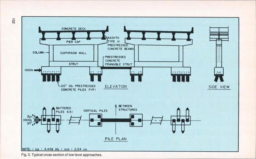
Fig. 3. Typical cross section of low level approaches.
level structure to resist. Measures suchas protective nets, pile barricades, ordolphins along the entire length of sucha long crossing are extremely expensiveand, in many instances, impractical.Therefore, it was necessary to make anevaluation and arrive at a rational solu-tion satisfying the stringent designcriteria.
The following design criteria for thelow level approaches were set prior tothis evaluation:
• The previously approved piershape had to be maintained. Thepier consisted of two columns con-nected with a pier cap, diaphragmwalls, strut above the footings, andindividual footings under each col-umn (Fig. 3).
• The superstructure consisting ofAASHTO Type IV beams and adeck with no intermediate dia-phragms was to be used.
The following limitations were ap-plied to the ship impact forces:
• Ultimate load of 1000 kips (4.45MN) was to be combined only withunfactored dead load.
• Ship impact load was to be as-sumed to be a static load applied atthe water level.
• Ship impact load was to be appliedonly at the outer, not inner, pilecaps (those that are exposed to anaberrant barge or ship).
• Ship impact angle was to be within±30 degrees measured in a hori-zontal plane from the pier center-line (see Fig. 3).
• The superstructure was not to bedesigned to resist direct ship im-pact forces.
• It was assumed that if the ship im-pact force to one of the roadways(northbound or southbound) weregreater than 1000 kips (4.45 MN), itwould damage the impacted road-way, but the adjoining roadwaywould remain undamaged andopen to traffic.
Geotechnical InvestigationEvaluation of a bridge's structural
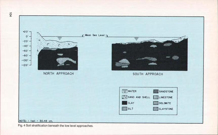
system for ship impact forces is influ-enced by the soil characteristics belowthe river bottom and the resulting de-flection of the piles. The stiffer the soil,the smaller the deflection of the top ofthe pile. In the area of the low level ap-proaches, as is usual in long approaches,the soil stratification and compositionvary (Fig. 4).
In the area of the north approaches,the water depth varies from 0 to 30 ft (0to 9.1 m), with a deep sand and shelllayer around elevation –55.00 ft (-17m). Below the sand and shell layer, clay,with intermittent silt and limestonepockets, predominates.
In the area of the south approaches,the water is shallower and varies indepth from 0 to 25 ft (0 to 7.62 m), with athin layer of sand and shell underlainmostly with clay. Sandstone and dolo-mite lenses are present in the clay at afew locations.
The project's geotechnical consul-tants, Schmertmann and Crapps, Inc.,performed an extensive geotechnicalfield investigation, including an elabo-rate field testing program. As a result ofthis program, the safe working load levelfor the 20 in. (51 cm) square prestressedconcrete piles was established at 150tons (1.33 MN), with an ultimate factorof safety of 2.25.
Vertical load on a pile was only onefactor in the puzzle to design a structurefor ship impact criteria. The large hori-zontal forces of a ship impact to anygiven pier also had to be accounted for.Either the piers would have to be verymassive, or, conversely, they wouldhave to be slender and flexible and solinked that a group of piers shared theship impact force. The flexible linkingof adjacent piers with a precast pre-stressed concrete frangible strut was thekey.
To simplify the analysis and at thesame time simulate the interaction of
PCI JOURNAUJuly-August 1988 103
r2 0'
0 . Mean Sea Level
—60' 6—80'
—120'
NORTH APPROACH SOUTH APPROACH
WATER SANDSTONE
SAND AND SHELL ;;;+:LIMESTONE
. CLAY DOLOMITE
®SILT CLAYSTONE
NOTE: I foot - 30.48 cm.
Fig. 4 Soil stratification beneath the low level approaches.
0
soil and structure, the "equivalent pointof fixity" approach was used to modelthe foundation system. Using method-ologies described in articles by Davis-son (1965, 1970), 1.2 Reese and Matlock(1956), 3 and Penizen (1970) and thefinite difference computer program de-veloped by Reese and his colleagues,the design team determined equiva-lent points of fixity for a unit pile ex-pressed as a depth below the mud linebeyond which the pile could be consid-ered fixed. Equivalent points of fixitywere evaluated based on an estimationof the moment curvature and deflectionof a unit pile.
Equivalent points of fixity for the lowlevel approaches of the structure can besummed up as follows:
• 15 ft (4.57 m) below mud line forpiers located in less than 15 ft (4.57m) of water.
• 12 ft (3.66 m) below mud line forpiers located in greater than 15 ft(4.57 m) of water.
The above values are an average forall the low level approach piers. How-ever, piers in the north approach haddeeper points of fixity than south ap-proach piers because of different soilconditions.
Individual pile deflections tend to begreater than a pile group's deflection.The final results of the frame analysis,using the equivalent points of fixity ap-proach, were compared to the individualpile deflections obtained from the pre-viously mentioned programs and werefound to be less than the deflection ob-tained for the individual piles.
Advantages of PrestressedConcrete to Resist Ship Impact
Throughout the low level approaches,precast prestressed concrete piles sup-ported a reinforced concrete pier. Thepiers supported precast prestressedconcrete I-beams, and a concrete deckwas poured on top (Fig. 3). In addition, aprecast prestressed concrete beam was
used as a frangible strut between thenorthbound and southbound roadwaypiers.
The authors believe the following ad-vantages make prestressed concrete thesuitable material to resist ship impact:
• The high load resistance of the pre-stressed concrete piles, both incompression and in tension.
• Ductility of the prestressed con-crete piles to transmit the excessloads to adjoining foundation ele-ments through the concrete piers.
• Ability of the stiff precast pre-stressed superstructure element totransmit the unresisted loads to theadjoining piers, without which, re-sistance to ship impact forceswould have been very difficult.
• Simple transfer connection both atthe foundations and at the bearinglevels to transfer the high ship im-pact forces.
• Saving in costs due to the elimina-tion of intermediate diaphragmsbecause of the stiff prestressedconcrete beams.
• Greater safety for the bridge notstruck, since the precast pre-stressed concrete frangible strutcan be designed to fail beforetransmitting too much load fromthe struck bridge to the adjacentone, endangering both. Thus, thestrut acts as a fail-safe mechanism.
Pile LayoutsSeveral pile group layouts were
thoroughly investigated. They rangedfrom six to ten piles at a pier, with thepiles at several horizontal angles andalso at different slopes. Most alterna-tives failed, due to either high compres-sion or high tension loads in the piles.Other alternatives, though theoreticallyfeasible, had to be discarded as imprac-tical since they were difficult toconstruct and were uneconomical. Withthe introduction of a precast prestressedconcrete frangible strut between the
PCI JOURNAL/July-August 1988 105
ON - - -
o I -
iihM -
2'-3"
INTERIOR SUPPORT
PRECAST PRESTR SSEDCONCRETE FRANGI E STRUT
VERTICAL PILES
Orn PILE GROUP NORTHBOUND ROADWAY8 COLUMN
13'-9' 1 13'-9"
PILE GROUP j BETWEENB COLUMN STRUCTURES
12'-6'
3'-10' 1 3'-IO" I
BATTERED PILESr------ --
3p,• 1000^ N
500 'N N I I ' —STRU' TiL---------JI'-10}" 2'-9' 2' 9' 2'-9" I 10
6-0" 6-0'
EXTERIOR SUPPORT PLAN
---------}--------- ^STRUT
I I PRECAST PRESTR^SSED— -. -- — — — —4----------_ l CONCRETE FRANGIBLE STRUT
9 • TH. CONC. I
° I I I--. •--•SEAL i ,EL. I^f1T1 T -^-r-i
^ — — ^^^
f 20' SO. PRECASTPRESTRESSED PILE I 1
ELEVATION
foot • 30.48 cm : I inch • 2.54 cm
Fig. 5. The constructed foundation system.
Fig. 6. Precast prestressed concrete piles being driven using template.
adjoining structures, a practical solutionwas achieved.
Using the frangible strut, two work-able pile layouts were developed forconsideration, a six-pile system in shal-low water and a seven-pile system indeeper water. The proposed six-pilesystem had four piles at the exterior andtwo piles at the interior supports,whereas the proposed seven-pile systemhad four piles at the exterior supportsand three piles at the interior supports(see Fig. 5).
Finally, after much evaluation anddiscussion, a seven-pile-per-pier ar-rangement (in both shallow and deeperwater) was selected for uniformity aswell as for its increased safety in lowwater areas. This scheme was accept-able to the FDOT, the Federal HighwayAdministration (FHWA), and the con-tractors. The piles are shown beingdriven and after cut-off in photographstaken after construction was started(Figs. 6 and 7).
Fig. 7. View of precast prestressedpiles after cut-off.
PCI JOURNAL/July-August 1988 107
Analytical ModelsThree levels of modeling were used,
representing first a single pier, then aseries of piers (from a single roadwaystructure), and finally two parallelmulti-pier roadway structures.
The first level was a simplified two-dimensional model of a single pier withits foundations and did not include thesuperstructure. This model was usedonly to help in designing the largerthree-dimensional models.
The second level was a three-di-mensional model of a four-span con-tinuous superstructure with the fivepiers of a single roadway. The indi-vidual piers were modeled as in thefirst-level model. No frangible strutconnection was included in this secondmodel. The results of the computer runof the second-level model clearlyshowed that a single structure was un-able to resist the ship impact forces.
At the final third level, the second-level model was extended to include thepiers and superstructure of the adjoining
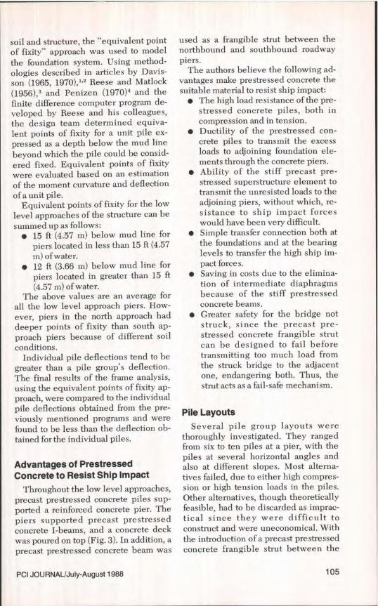
structure, connected through the precastprestressed concrete frangible struts(Fig. 8).
In all of the above, the piles weremodeled as individual columns, fixedtop and bottom. The battered piles inthe exterior pile caps intersected thevertical center of gravity of the cap inorder to reduce the moments in thepiles. The diaphragm walls between thecolumns were idealized into a grid. Inthe second and third levels, the com-posite section of the superstructure wasmodeled as a series of line elements.The transverse continuity of the deckwas simulated by the diagonal bracingelements, which helped to create theeffect of a horizontal truss for transfer ofloads from one pier to the next. At thebearing levels only the lateral and lon-gitudinal moments were released. Thebehavior of the elastomeric bearing padswas considered as a longitudinal spring,but since the effect was minimal, it wasdiscarded.
Fig. 9 shows the plan view of the
x;11 i= : ,•.
• ••
•0 •
•
Fig. 8. Isometric view of final computer model.
108
CC-0CI,z
C-C
CCDCc
COm
PIER PIER . PIER PIER I PIERt
'1.60'2.40' 1.60'
3Ok C 48k T 325k T 367k 365k T 323k 48k T 3ok C
1.60"^\\ 60k C 7 k C 329k C 370k C k k 73k C 60k C
1.60"
FRANGIBLE 2'40 BETWEEN _
STRUT (TYP.) 2.51' (DEFLECTIO -TYP.) STRUCTURES
I.56"Y1'.56
1.56"1.56 I I 2.51'
T TENSION t 1000kC COMPRESSION PLAN OF DECK
NOTE: I kip 4.448 kN : I inch • 2.54 cm
Fig. 9. Distribution of forces and deck lateral deflection from a ship impact at continuous deck pier.
50k 28k 7 372k 439k 442k 375k 29k 49k G
48k C 55k C 378k C 441k C 446k C 381k C 56k C 49k C