D a n s e r e a u D e n t a l Super Flow 10 Dry Vacuum
Table of Contents
Section 1 - Vacuum Pump
Section 2- Pre-installation Guide
Section 3 - Unpacking
Section 4 - Installation
Section 5 - Maintenance
Section 6 - Trouble Shooting Guide
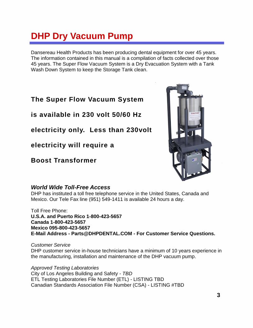
DHP Dry Vacuum Pump Dansereau Health Products has been producing dental equipment for over 45 years. The information contained in this manual is a compilation of facts collected over those 45 years. The Super Flow Vacuum System is a Dry Evacuation System with a Tank Wash Down System to keep the Storage Tank clean.
The Super Flow Vacuum System
is available in 230 volt 50/60 Hz
electricity only. Less than 230volt
electricity will require a
Boost Transformer
World Wide Toll-Free Access DHP has instituted a toll free telephone service in the United States, Canada and Mexico. Our Tele Fax line (951) 549-1411 is available 24 hours a day. Toll Free Phone: U.S.A. and Puerto Rico 1-800-423-5657 Canada 1-800-423-5657 Mexico 095-800-423-5657 E-Mail Address - [email protected] - For Customer Service Questions. Customer Service DHP customer service in-house technicians have a minimum of 10 years experience in the manufacturing, installation and maintenance of the DHP vacuum pump. Approved Testing Laboratories City of Los Angeles Building and Safety - TBD ETL Testing Laboratories File Number (ETL) - LISTING TBD Canadian Standards Association File Number (CSA) - LISTING #TBD
3
DHP Vacuum Pump - Pre-installation Guide Location The DHP Super Flow Vacuum System should be installed in a well ventilated area. The DHP Super Flow Vacuum System is air cooled and without proper air circulation the lifespan of the vacuum pump could be shortened significantly. The sound level of the vacuum pump, when in operation, is very quiet and can be placed within a dental facility. The ambient temperature in the dental office equipment room should never ex-ceed 40 degrees Fahrenheit minimum and 100 degrees Fahrenheit maximum. The dental office equipment room will require a minimum 5 air changes per hour which can be met with a 50 CFM vent fan in a 5' x 5' x 9' room. However, if an Air Condition-ing Supply and Return is available it is HIGHLY RECOMMENDED to ensure heat controls in the Utility Room. NOTE THE SUPERFLOW DRY VAC CAN BE INSTALLED SIDE BY SIDE OR STACKED.
The above DHP Super Flow Dry Vacuum System Vacuum installation elevation is a typical installation.
It should be noted that local building codes will supersede any recommended installation guidelines in this manual.
4
DHP Dry Vacuum Specifications
Specifications:
Voltage 230 VAC / Hz 50 - 60 - If 208 Present "Buck Booster Required "
• Output H.P. - 2 / Current Amps 11
• Free Delivery (CFM) 70 / Vacuum In. Hg. 16" max 8" continuous
• Weight (lbs.) 97
• Width (inches) 16
• Length (inches) 20
• Height (inches) 16
• Tank (gallons) 16
• Includes: Low voltage control, separator tank with automatic drain and check valve
• Copper NO LONGER RECOMMNDED FOR VACUUM LINES OR VENTING
Number of Operatories
Vacuum Line
Diameter
PVC Sch. 40
Assembly Diameter
PVC Sch. 40 Dry Vacuum System
1 1 1/4” ” 1 Dry Vacuum System
2 1 1/4” 1 Dry Vacuum System
3 1 1/4” 1 Dry Vacuum System
4 1 1/4” 1 Dry Vacuum System
5 1 1/4” 1 1/ 2” 1 Dry Vacuum System
6 1 1/ 2” 1 Dry Vacuum System
7 1 1/ 2” 1 Dry Vacuum System
8 1 1/ 2” - 2 ” 1 Dry Vacuum System
Dry Vacuum System 9 2” 1
Dry Vacuum System 10 2” 1 1 / 4”
Dry Vacuum System 11 2” 1 1 / 4”
Dry Vacuum System 12 2” 1 1 / 4”
5
DHP Dry Vacuum Pre Installation
Typical Errors in Plumbing Vacuum Lines
Typical Errors in Plumbing Vacuum Lines
6
DHP Dry Vacuum Pre Installation
Vacuum Line: See Chart Page 4.
Surface Mt J Box
1” Sch 40 PVC
1” - 1.5” Bushing Sch 40 PVC
1.5” DWV Sanitary T Sch 40 PVC
Dansereau Health Products, Inc. strongly recommends Schedule 40PVC for use as the Vacuum Line. However, be aware some Building Codes require a metal type vac-uum line and require Copper as the Vacuum Line. Cop-per will eventually deteriorate over years of service, Schedule 40 PVC will not. NOTE: IF YOUR VACUUM LINE INSTALLATION IS OUTSIDE THE SCOPE LISTED BELOW CONTACT DANSEREAU FOR SPECIAL INSTRUCTIONS.
Site Requirements: Environment Conditions
Operating Conditions - Indoor use at altitudes up to 2000M.
Temperature 5 to 40 Degrees C (41 to 104 F)
Maximum relative humidity 80% for temperatures up to 31 C, decreasing linearly to 50% relative humidity to 40C.
Supply Voltage fluctuation of +/- 10% of nominal voltage.
IEC 60601 - 1 Not suitable for use in the presence of a flammable anesthetics mixture with air or with oxygen or nitrous oxide.
Class 1 Installation Category
Ordinary equipment (IPXO). Does not protect against ingress of water. Unit is suitable for continuous operation.
7
Operatory Termination - See Vacuum Sizing Chart for Specs.
Main Trunk Line - See Sizing Chart
Branch Line - See Sizing C
hart
To Vacuum System
DHP Dry Vacuum Specifications
OVERHEAD PLUMBING Overhead plumbing for dental vacuum lines are not recommended. Our experience in the long term
there can be issues with quality of vacuum. However, if it is required based upon existing conditions in
a dental office, economic considerations or construction limitations you will need to be exact in following
the rules listed below. Incorrect installation of overhead vacuum piping will ensure low quality or non
existent vacuum pressure.
Plumbing Rules for Overhead Piping:
Keep the vertical lift height as short as possible.
The vertical pipe must tee into the top of the horizontal line.
Run the vertical line in 1/2” pipe.
Run the horizontal overhead line in 1-1/2” or preferably 2” size pipe. For more than 5 Operatories
consult with Dansereau.
Nitrous oxide scavengers must run in a separate vertical pipe and tee into the top of the horizontal
line in a separate location from the “ wet “ vertical pipe.
Pump Sizing Rules for Overhead Piping:
Dry Vacuum System is only recommended Vacuum System.
Consult with Dansereau on Overhead Piping Line Size.
Operator Rules for Overhead Piping:
Operators must use Non Foaming Vacuum Line Cleansers ( Recommended Bio-Pure)
Operators must flush lines and then allow air from open vacuum line to run in order to ensure com-
plete liquid non foaming vacuum line cleaning solution has run through the system.
Vertical Pipes Must Tee Into Top of Horizontal Overhead Pipe
General Principles for Vacuum Lines Slope a minimum of 1/4” in 10 feet with the low end towards the tank. If an in-line low spot is unavoidable, place it in a known loca-tion and incorporate a “ Clean Out “. Confirm All Local Building Codes prior to beginning plumbing.
DHP Dry Vacuum Pre Installation
8
DHP Dry Vacuum Specifications
Electrical Requirements LINE VOLTAGE - Single phase 240v/50/60hz electricity is required for proper opera-tion of the D H P Dry Vacuum System. All electrical sources to the DHP Vacuum Pump MUST BE PROPERLY GROUNDED! All DHP Dry Vacuum Systems are operated by a LOW VOLTAGE SWITCH or the AUTO WASH DOWN SYSTEM WILL NOT OPERATE. LOW VOLTAGE - A 18/3 low voltage rated wire should be run from one central loca-tion to allow the DHP Dry Vacuum System to be turned on and off.
Plumbing Requirements WATER LINE - A 1/2" cold water source is required for proper operation of the DHP Dry Vacuum System Wash Down. A 1/2" shut off valve is required at end of the water source. Cold water is an important requirement for the proper operation of the DHP Vacuum Pump. WASTE LINE - The industry standard for exhausting the Dry Vacuum waste into a floor sink Local Building Codes will require a 1" air gap from the exhaust of the Dry Vacuum Waste Outlet into the floor sink. SPECIAL NOTE: The Dry Vacuum Motor will require a 2 Inch Vent from the Exhaust of the Motor thru the roof to outdoors. It is required that the first 8 feet (minimum) of the vent pipe from the Dry Vacuum Motor be of metal consistency (No Plastic). Recom-mended Galvanized. The exhaust of the Dry Vacuum Motor can be hot over constant usage. After the first 8 feet of metal vent pipe you may use a Schedule 80 ABS, pro-vided there are not bends or angles in the line, straight exhaust.
Vacuum Line The industry standard is a 1.5" schedule 40 PVC line reduced to a 1" schedule 40 PVC line at the operatory. Schedule 40 PVC is the only Manufacturer Recommended product for Dental Vacuum Lines. Vacuum Pump Specifications: Total Horsepower - 2 Electrical 240V - Buck Boost Transformer may be required if only 208V is present. Maximum Users: High Volume Evacuation (HVE) - 4 High Volume Evacuation & Saliva Ejectors - 2 (HVE) & 4 (SE) Tank Dimensions: Height - 36 Inches / Depth - 21 Inches / Width - 21 Inches Motor Dimensions: Height - 19 Inches / Depth - 24 Inches / Width - 24 Inches Weight - Tank 45lbs / Motor - 110lbs
UNDER NO CONDITIONS SHOULD CONTINUOUS RUN SINKS OR DENTAL CUSPIDORS BE INSTALLED ON A VACUUM LINE
9
Dansereau Super Flow 10 Installation
1) The Super Flow 10 ships full assembled. It will arrive ready to install
with no product assembly required. 2) Set the Super Flow 10 into the Utility Room making sure there is ade-
quate air flow and clearances around the system. Noting this is an air cooled system and good air flow is imperative. In some cases we have seen dentists have an air conditioning duct run into the Utility Room.
3)
Operatory Intake
Turbine Exhaust Vent
Wash Down Water Source - Blue Hose (Not in Picture). Wash Down System is not required for opera-tion, but will eliminate tank cleaning maintenance
Electrical Power Source Line ( Not In Picture) 240V required.
Low Voltage Control Wires - Do not cross will result in failure of low voltage transformer
Vacuum Waste Line to drain waste into public waste receptacle - Floor Sink is recommended.
Special Note: Do not adjust the CFM on the Vacuum System unless you consult directly with the Dansereau as over adjusting the CFM may cause particulate matter to be drawn into the Vacuum Motor. A Particulate Matter
Filter is in place to prohibit the introduction of matter from the Storage Tank into the Vacuum Motor, but over adjusting the CFM will strain the
Particulate Master Filter and cause motor damage.
10
Dansereau Super Flow 10 Maintenance
A) Particulate Matter Filter - Inspect Monthly for Moisture. This is a key indicator that liquid / foam is be “ Sucked Up “ from the Separator Tank into the Turbine. This will also restrict air flow causing the motor to overheat and prematurely fail. If you have moisture or liquid in this filter contact Dansereau immediately.
B) Separator Tank Waste Line should be inspected to ensure waste if flowing after the Dry Vac-uum system is turned off. When Vacuum System is turned off flow of waste from Separator Tank is immediate. Visual inspection is adequate.
How to Inspect the Filter: 1) Turn off Vacuum System. 2) Wearing Gloves and Mask lift
the retain brackets. 3) Lift Top of Filter and Inspect.
C) Wash Down System inspection: The Super Flow has an integrated Wash Down System on timer. Approximately 5 Min-utes after shut down of the Vacuum System Wash Down will commence for approximate 1 minute - 1 Gallon of Water is used to rinse the inside of the Sepa-rator Tank. If you experience more that approximately 1 minute or excessive water during the wash down cy-cle contact Dansereau immediately.
The Super Flow 10 Dry Vacuum system is virtually a maintenance free vacuum sys-tem. A few items to inspect during operation and proper vacuum line maintenance will ensure you that your Super Flow Dry Vacuum system will give you years of op-eration
11
Dansereau Super Flow 10 Installation
1) Electrical installation must be performed by an licensed Electrician.
2) Low Voltage Controls must be installed to properly operate the wash down system
3) Dry Vacuum Motor must be properly grounded.
12
Dansereau Super Flow 10 Maintenance
Maintenance: The Super Flow 10 Dry Vacuum System requires no maintenance or service. However, as this is a mechanical device we recommend monthly inspections of the system. Look for a situation that appears abnormal, moisture and noise etc... NON FOAMING VACUUM LINE CLEANSERS MUST BE USED DO NOT USE BLEACH TO CLEAN VACUUM LINES IT WILL DAMAGE THE STAINLESS STEEL TANK. Dansereau recommends Bio - Pure Dental Line Cleaner. Call (800) 423 -5657 for Special Dansereau pricing. Twice Monthly check the In Line Particulate Matter filter for moisture or particulate matter. If moisture or particulate matter is present contact Dansereau immediately.
NEVER ADJUST THE PRESSURE RELIEF VALVE. Once a Month Inspect the Pressure Relief Valve for Dust
and Particulate Matter
Trouble Shooting: Motor making loud winding sound: A) Turn off motor immediately and contact Dansereau (800) 423 - 5657 Motor not turning on: A) Check the fuse at the Electrical Panel in the dental facility.
B) Check the Fuse on the Super Flow Dry Vacuum
C) Check the connections on the low voltage control panel
D) Contact Dansereau immediately (800) 423 - 5657
Introduction of any foreign matter into the vacuum motor will damage the integrity of the motor and may void the warranty. We have installed a par-ticulate matter filter to prohibit the foreign matter passing through to the
vacuum motor. However if you are using Air Abrasion you must have an In Line Filter. Failure to use the appropriate filter will void your warranty
13
Dansereau Super Flow 10 Maintenance
Warranty: 1 Year: Solenoid Valve, Internal Relay and Tank Sensor Electronic components are covered by 1 year. Shipping, labor and installation costs are borne by the user. 3 Years : Turbine Motor. The turbine motor is covered for 3 years under normal use conditions. If there is excessive heat, foreign matter is introduced into the turbine, foaming line cleansers, bleach or bleach like products are used the warranty is voided. Shipping, labor and installation costs are borne by the user. 5 Years: Stainless Steel Tank: Stainless Steel Tank and Structure are covered by a 5 year warranty. Bleach and Bleach like prod-ucts that are used to clean the vacuum lines will void the war-ranty. Special note: Air abrasion and particulate matter used in air abra-sion will damage the dry vacuum system. If they are being used an inline filter must be used to eliminate the possibility of dam-age. Do not use Foaming Vacuum Line Cleaners, Bleach or Bleach like products with our Dry Vacuum System. Periodically check the Dry Vacuum Filter for moisture, if you find moisture contact Dansereau immediately. Replace the filter ad-justments will need to be made of to the dry vacuum system to ensure no premature failure occurs. Dansereau’s warranty does not imply or express any conse-quential damages will be covered under this warranty. Labor and shipping costs will be borne by the user.