54
Technical Reference For Modicon PLCs Merrick Industries, Inc. 10 Arthur Drive Lynn Haven, FL 32444 (850) 265-3611 Revision 1.14, June 13, 2000

Technical Reference For Modicon PLCs
Merrick Industries, Inc. 10 Arthur Drive Lynn Haven, FL 32444 (850) 265-3611
Revision 1.14, June 13, 2000

Superbridge Modicon i
Revision Notes
0.11A 10/30/95;LTM First complete issue for beta version
0.20 02/08/96;BPM;LTM Updates for ver 0.20 release
0.20A 06/12/96;LTM Corrections at release build
0.99 03/08/98;LTM Updates for ver 0.99 release
1.10 07/04/98;LTM Updates for ver 1.10 release
1.14 06/13/00;RWM Updated for 1.14 release
PROPRIETARY NOTE
The information in this manual, including technical data and copies of drawings, embodies information proprietary to Merrick Industries, Inc. and this manual is provided to the user of equipment purchased from Merrick Industries, Inc. for use only in operation or maintenance of such equipment. Such information in this manual is not to be used, disclosed, copied, or reproduced in whole or part for any use other than that indicated above, or for any other purpose detrimental to the interests of Merrick Industries, Inc. Patents owned by Merrick Industries, Inc. have been issued or are pending on at least some of the information in this manual, and unauthorized use of this subject matter of such patents is a violation of such patents and is prohibited.

Superbridge Modicon ii
INTRODUCTION ..............................................................................................................................1
PLC connectivity........................................................................................................................1 Control Room software connectivity .........................................................................................1 MC Controllers connectivity ......................................................................................................1 Hardware Requirements ...........................................................................................................2
SETTING UP A SYSTEM.................................................................................................................3 INSTALLING SB SOFTWARE AND HARDWARE.......................................................................3
Assign Node Numbers ..............................................................................................................3 Install the SA-85 Card ...............................................................................................................4 Install RS-422 converter or adapter, if needed .........................................................................4 Install RS-422 multiport adapter, if needed...............................................................................4 Modify PC configuration ............................................................................................................5 Verify SB startup .......................................................................................................................6
SETTING UP COMMUNICATIONS WITH THE MCS..................................................................6 MC Physical Connection ...........................................................................................................6 MC Communication Parameters ...............................................................................................7 SB Configuration for MCs .........................................................................................................7 Verify MC communication .........................................................................................................7
SETTING UP PLC CONTROLLERS FOR REGISTER COPY.....................................................8 Allocating Holding Registers .....................................................................................................8 SB Configuration for Segment Copy.........................................................................................9 Connecting SB to MB+..............................................................................................................9 Verify MB+ Segment Copy........................................................................................................9
PLC HOLDING REGISTER ARRAY SPECIFICATION .................................................................10 Integer Report Array................................................................................................................10
MC Status Word, IR:0,8,16..................................................................................................10 MC Internal State, IR:1,9,17.. ..............................................................................................11 MC Digital I/O, IR:2,10,18....................................................................................................11 MC General Alarms or Warnings, IR:3,11,19......................................................................12 Request Done Bits, IR:4,12,20.. ..........................................................................................12 Request Error Bits, IR:5,13,21.............................................................................................12 Request Integer Result, IR:6,14,22.. ...................................................................................12 External Outputs, IR:7,15,23.. .............................................................................................12
Integer Control Array...............................................................................................................12 Fast Tag MC Register Number, IC:0,7,14...........................................................................13 Slow Tag MC Register Number 1 - 3, IC:1-3,8-10,15-17.. ..................................................13 MC Control Word, IC:4,11,18.. ............................................................................................13 MC Request Integer Parameter IC:5,12,19.........................................................................14 External Inputs, IC:6,13,20.. ................................................................................................14
Float Report Array ...................................................................................................................14 Fast tagged value, FR:0,8,16.. ............................................................................................15 Slow tagged values 1 - 3, FR:1-3,9-11,17-19......................................................................15 Process Value, FR:4,12,20..................................................................................................15 Total, FR:5,13,21.. ...............................................................................................................15 Request Float Result FR:6,14,22.. ......................................................................................15 Reserved, FR:7,15,23.. .......................................................................................................15
Float Control Array ..................................................................................................................15 SetPoint, FC:0,3,6.. .............................................................................................................15 MC Request Float Parameter, FC:1,4,7..............................................................................15 Secondary SetPoint, FC:2,5,8.. ...........................................................................................15
SLAVE MESSAGES PROCESSING SPECIFICATION.................................................................16 Read Holding Registers ..........................................................................................................16 Preset Multiple Registers ........................................................................................................16 Preset Single Registers...........................................................................................................16

Superbridge Modicon iii
MODEL SPECIFIC INFORMATION...............................................................................................17 SUPPORTED FUNCTIONS .......................................................................................................17 PROCESS VALUE......................................................................................................................18 SETPOINT ..................................................................................................................................18 GENERAL ALARMS...................................................................................................................18 DIGITAL I/O ................................................................................................................................19 INTERNAL STATE......................................................................................................................20
30.00.HP .................................................................................................................................20 35.00.HP .................................................................................................................................21
USEFUL MC REGISTERS .........................................................................................................21 20.00.K ....................................................................................................................................22 22.00.B ....................................................................................................................................23 30.00.D....................................................................................................................................23 10.00.HP .................................................................................................................................24 11.00.HP .................................................................................................................................25 20.00.HP, 24.81.HP ................................................................................................................25 30.00.HP .................................................................................................................................26 35.00.HP .................................................................................................................................27 24.96.EX..................................................................................................................................28 30.10.EX..................................................................................................................................28 24.10.EX..................................................................................................................................29
DIAGNOSTIC SCREENS...............................................................................................................30 THE HOME SCREEN.................................................................................................................32 MC DATA SCREEN....................................................................................................................33 MC COMBINED DIAGNOSTIC SCREEN ..................................................................................35
Numerical Error Values ...........................................................................................................37 MB+ SEGMENT COPY DIAGNOSTIC SCREEN.......................................................................38 MB+ PATH DIAGNOSTICS SCREEN........................................................................................40 MB+ SLAVE MESSAGES DIAGNOSTICS SCREEN.................................................................42
CONFIGURATION .........................................................................................................................44 [SIZES] SECTION.......................................................................................................................44
ComPorts.............................................................................................................................44 Controllers ...........................................................................................................................44 Segments.............................................................................................................................44
[IRQ] SECTION...........................................................................................................................44 PortVector............................................................................................................................44 PIDMask ..............................................................................................................................44
[PORTN] SECTIONS..................................................................................................................44 UartBase..............................................................................................................................45 DLABReg.............................................................................................................................45 Retries .................................................................................................................................45
[MCN] SECTIONS ......................................................................................................................45 Used ....................................................................................................................................45 Timeout................................................................................................................................45 WatchDog............................................................................................................................45 ReviveTime..........................................................................................................................45 ControllerNumber ................................................................................................................45 Port ......................................................................................................................................46
[MODATA] SECTION..................................................................................................................46 [PLCDEFAULT] SECTION..........................................................................................................46
DefaultPath ..........................................................................................................................46 MCPerSegment ...................................................................................................................46
[SEGMENTN] SECTION.............................................................................................................47 SourceAddress ....................................................................................................................47 DestAddress ........................................................................................................................47

Superbridge Modicon iv
Elements..............................................................................................................................47 Path .....................................................................................................................................47 TimePeriod ..........................................................................................................................48 MBPTimeout ........................................................................................................................48 TfrType ................................................................................................................................48
[DATASLAVE] Section ............................................................................................................48 Path .....................................................................................................................................48
[ADAPTER] Section ................................................................................................................48 SWInterrupt..........................................................................................................................48
REFERENCES ...............................................................................................................................49

Superbridge Modicon 1
INTRODUCTION
SuperBridge (SB) is a software application that provides two-way communications between Merrick MC²/MC³ controllers (MCs) and Modicon’s (MO) communication network Modbus Plus (MB+). Status and variables in MCs will appear on MB+ as integer and floating point holding registers in a MO controller, such as the 984 or Quantum series of MO controllers (PLC).
SB will run on an industrially hardened personal computer compatible platform (PC), under MS-DOS, with the addition of a MB+ communication adapter board. Up to 128 MCs can be connected one SB. On the MB+ network, SuperBridge will support messages, such as Read Holding Registers and Preset Multiple Registers. In addition, MC data can be automatically exchanged with one or more PLCs on MB+.
PLC connectivity
The ladder programmer can access MC data in two different ways:
• Copy holding registers to a Modicon controller. SuperBridge maintains MC data in the holding register area (4xxxx registers) in one or more PLCs. This imposes minimal burden on the ladder programmer and PLC memory resources. Holding registers are continuously updated in the PLCs by the SuperBridge with MC general status, status of digital inputs and outputs, feedrates, totals, alarms and other parameters. The ladder programmer can access an MC² keyboard and tag specific data items for monitoring and manipulation. The MCs are completely accessible to the PLC. This also means that the PLC can act as an advanced version of MasterSet and as a sophisticated sub-system to weighing controllers, all at the same time.
• Slave message processing. The PLC requests MC data from SB. This imposes minimal burden on the MB+ communications bandwidth and on the PLC performance. The ladder programmer creates rungs with MSTR instructions to read or write data from or to SB. This method gives the same level of control as does the copy method above, but the ladder logic programming effort is greater. For very large systems, this method has an advantage.
It is also possible to use a combination of the two methods.
Control Room software connectivity
Most modern control room or on-line QA monitoring software packages (MMIs) such as Rockwell Software’s RSView and Intellution’s Fix Dmacs for Windows support MO connectivity over MB+. This support is available regardless of the presence of a MO PLC system. The MMI accesses MC data just as any PLC data, normally using the “Slave message processing” method described above. This makes a MC/SB installation open to almost all modern, powerful control and QA systems.
MC Controllers connectivity
Up to 128 MC² or MC³ controllers can be connected to a SB, using using up to four RS-485, four-wire connections. MC² controllers must be equipped with a serial port option. A serial port can easily be added to an existing controller. Some older versions of the controller software must be upgraded. See Model Specific Information (page 17). The system response time will improve with decreasing number of MCs connected. If very fast response times are required, more than one SB can be installed on a MB+ network.

Superbridge Modicon 2
Hardware Requirements
SB runs on a personal computer, at least 386/25, with 2 Mbytes of RAM, 5 Mbytes of Hard Disk space and one available serial port, COM1 or COM2. The serial port must either be a RS-422 port, or an adapter must be used to convert RS-232C signal levels to RS-422. When many controllers are connected, a four port serial adapter can be used. Up to 32 MCs can be connected to one RS422 serial port. The PC has to be equipped with a Modicon SA-85 adapter, serving as an interface between the PC ISA bus and MB+.

Superbridge Modicon 3
SETTING UP A SYSTEM
Setting up a SB system includes the following steps:
1. Verify that existing MCs are equipped with a RS-485 Serial Port and have software application versions listed in Model Specific Information (page 20). If not, complete and/or upgrade.
2. Assign a MB+ node number for SB. See Assign Node Numbers (page 3)
3. In the PC, install SA-85 (Modicon part number AM-SA85-000) adapter and, if needed, a RS-232/RS-422 converter. See “Install the SA-85 Card” (page 4) and “Install RS-422 converter or adapter, if needed” (page 4)
4. Copy the SB software files to the PC hard disk and modify the PC configuration files if necessary. See Modify PC configuration (page 5)
5. Verify that SB starts up properly in the PC. See Verify SB startup (page 6).
6. Connect all MCs to SB. See MC Physical Connection (page 6).
7. Set up communication parameters in all MCs connected. See Setting Up communications with the MCs (page 6).
8. Configure SB for the number of MCs connected. See SB Configuration for MCs (page 7)
9. Verify that communications with the MCs work properly. See Verify MC communication (page 7)
10. If data is to be copied from SB to one or more PLCs, the file copy scheme must be set up and verified. Use the steps 11..14.
11. Reserve holding registers in the host PLC(s) to hold SB data. See Allocating Holding Registers (page 8).
12. Configure SB to read and write the holding register segments. See SB Configuration for Segment Copy (page 9)
13. Connect SB to the MB+ network. See Connecting SB to MB+ (page 9).
14. Verify that the register copy process works properly. See Verify MB+ Segment Copy (page 9)
INSTALLING SB SOFTWARE AND HARDWARE
If SB hardware and software are purchased entirely from Merrick, it comes installed and configured along with a specification sheet. The configuration may have to be altered as the system changes.
SB will run on a generic PC according to Hardware Requirements (page 2). If configuration data was available to Merrick before the time of shipment, the configuration file has already been prepared. In any case, a specification sheet is always shipped, indicating the current configuration.
Assign Node Numbers
SB will act as a PLC on MB+. As such, it must be assigned a MO style node number. Check that there are no node number conflicts on the MB+ network, and set the node number dip switch on the SA-85 adapter according to instructions in [2], page 43, if needed. If more than one SB resides on the MB+ network, they must all have different node numbers.

Superbridge Modicon 4
Install the SA-85 Card
Configure and install the SA-85 card in the SB host PC, according to instructions in [2], section 3.2. Since SB normally is the only application running on the host PC, it is recommended that the default settings are used, that is,
• Memory address: D400 ([2], page 45)
• Software Interrupt Setting: 5C. ([2], page 9)
The MB+ Node Number must also be set. See [2], page 43.
If a NetBios compatible network driver is loaded in the PC, software interrupt 5C can not be used. 5D or 60 are good alternatives. Note that changes must be made to the SB configuration file (SUPERB.INI) and to CONFIG.SYS.
If there are other devices that may cause a conflict with these settings, other settings can be examined. The corresponding configuration files (CONFIG.SYS and SUPERB.INI) must me altered accordingly. See Modify PC configuration (page 5).
Install RS-422 converter or adapter, if needed
If the host PC does not have a RS-422 serial port, a converter between RS-232 and RS-422 must be used. Alternatively, an internal RS-422 adapter board may be used. Make sure to disable the corresponding RS-232 COM port!
Merrick has successfully tested the ULTRA-485 serial port adapter from Industrial Computer Source, (619) 677 0877. Strappings for COM 1 for this board are:
• Port Adress to 3F8. SW1 = On, On, On, Off
• IRQ Jumper to IRQ4. E1 = Jumper @ 4
• Single Interrupt mode. E2 = Jumper @ N
• RS-422 mode. E5 = Jumper @ 422
• RS-422 mode. E3 = Jumper @ 422
• SIO-485 Mode. E4 = Dip Shunt @ SIO-485. This is not the default setting.
• Line terminations on. SW-2 = (T,P,P,L,L) = (On, On, On, Off, Off).
For COM2, the following strappings would change to:
• Port Adress to 2F8. SW1 = On, On, Off, On
• IRQ Jumper to IRQ3. E1 = Jumper @ 3.
Install RS-422 multiport adapter, if needed
If more than 32 MCs are connected to the host PC serial port, or to increase performance, a multi-port RS-422 adapter must be used. Up to 4 serial ports, sharing a single interrupt (IRQ), are supported.
Merrick has successfully tested the FASTCOM422/4 serial multiport adapter from Industrial Computer Source, (619) 677 0877. Strappings tested for this board were:
• Port Adress Base to 280. SW1 = On, On, Off, On, Off, On, On, On
• IRQ 3, No IRQ Sharing. SW2 = On, Off, On, Off, Off, Off, Off, Off, SW3 = Off, Off, Off, Off. This is not the factory default setting. The factory default is IRQ5. In the test computer, IRQ5 was used by the A-B KT adapter. No COM2 port, which uses IRQ3, was installed in the test computer.

Superbridge Modicon 5
• CTS Handshaking disabled, No RTS Tx driver control. SW4 = On, On, On, On, Off, Off, Off, Off.
Modify PC configuration
The SB software files are distributed as a complete directory structure, including all configuration files. For a pre-configured system, the files are installed along with MS-DOS on the PC hard drive. In all other cases, the SB files are shipped on a 3½” floppy, and the files have to be copied onto the PC hard drive. MS-DOS, versions 5 or 6, must already be installed. To copy the SB files onto the hard drive insert the distribution diskette in the floppy drive (assumed to be drive A:), boot the PC, and at the C:\> prompt, type
XCOPY A:*.* /S /E /V and hit return. The existing AUTOEXEC.BAT and CONFIG.SYS files will be overwritten and the following directories will be created:
\SUPERB SB executable and configuration files
\MODICON Modicon driver file and diagnostic programs
\DOC Specific release or configuration text files.
MS-DOS files are assumed to reside in \DOS.
Three files deals with the SB configuration and are referenced below as
SUPERB.INI \SUPERB\SUPERB.INI
AUTOEXEC.BAT \AUTOEXEC.BAT
CONFIG.SYS \CONFIG.SYS
They can all be edited with the MS-DOS editor ‘EDIT’.
SUPERB.INI, with its many configuration entries, is described in detail in Configuration (page 44).
The default AUTOEXEC.BAT looks like this REM AUTOEXEC.BAT REM SuperBridge for Modicon Default REM 10/30/95/LTM PATH=C:\DOS;C:\MODICON;C:\SUPERB CD SUPERB MODRV
There is normally no reason to alter this file. The last two rows must always be present and unchanged.
This is the default CONFIG.SYS REM CONFIG.SYS REM SuperBridge for Modicon Default 0.99 REM 03/08/98/LTM BUFFERS=15,0 FILES=8 DEVICE=C:\MODICON\MBPHOST.SYS /MD400 /N0 /S5C /R2 DEVICE=C:\DOS\INTERLNK.EXE
The INTERLNK driver load (line 9) is always attempted. It will fail if no Interlink server PC is connected to COM1. This is for the benefit of PC card Flash EPROM disk installations. The intersvr/interlnk utilities is the only way to transfer files to and from the SB host PC.
SB will always start at boot, showing its home screen. To be able to edit configuration files, exit SB by pressing F10.

Superbridge Modicon 6
Verify SB startup
Connect a VGA monitor and PC keyboard to the SB host PC and reboot. Watch for error messages as SB starts up. The load process can be made to run step-by-step by holding down the F8 key immediately after boot. If SB starts successfully, the SB home screen will appear.
If possible, run MBPSTAT ([2], page 143) on another device on the MB+ network. With the default settings, SB should appear an active node on MB+. MBPSTAT is can also be used in your local SB host PC, to verify that the SA-85 adapter is installed properly.
SETTING UP COMMUNICATIONS WITH THE MCS
The MC network is a four wire RS-485 Master-Slave polled communications loop. All MCs are slaves on the network, and are required to have a RS-485 serial port and a unique address, called “Controller Number” (CN). The CN is set up, along with other serial communications parameters, in each MC. SB is the master, and must have either a four wire RS-485 or a RS-422 serial port. All serial ports are connected along one shielded, 4 wire cable.
MC Physical Connection
Use a RS-422 type two pair, four wire shielded cable like Belden ERROR. One pair is used to carry signals from the SB transmitter to all MC receivers. The other pair is used to carry signals from all MC transmitters to the SB receiver. The following table lists connections. Check with the documentation for the RS-422 adapter used for the pinout.
SB Signal
ULTRA -485 Pin # (DB-25P)
FASTCOM 422/4 Pin # (DE-9 S)
MC³ Controller Terminal #
MC² Controller Pin # (DB-25S)
MC Signal
Tx+ 24 4 3 22 Rx+ Tx- 25 5 4 23 Rx- Rx+ 12 8 1 24 Tx+ Rx- 13 9 2 25 Tx-
Shield 7 1 N.C. 11 Shield
Be careful when running the cable. Avoid power lines and other devices that might cause electrical disturbances. Maximum cable length is 1230 m (4000 ft). SB does not have to be connected at one end of the cable. Remove all termination resistors in the MC² serial ports. Add a 150Ω terminating resistor between the + and - lines for each pair at each end of the cable.
If only one MC² is used, it is possible to use a RS-232 interface instead. This is useful for bench-testing SB, using a regular office PC, which normally has no RS-422 interface. The cable should have a DE-9S, for a 9 pin connector in the PC or a DB-25S, for a 25 pin connector in the PC in the PC end and a DB25P in the MC end. Use the following table for the pinout, and keep the cable length less than 25 feet at 19200 baud.
Signal, PC Side PC COM port, 9 pin (DE-9P)
PC COM port, 25 pin (DB-25P)
MC² Serial port (DB-25S)
Rxd (PC reciever) 2 3 15 Txd (PC transmitter) 3 2 12 Ground 5 7 7 Shield 1 1 1

Superbridge Modicon 7
MC Communication Parameters
MC Communication parameters are set in the controllers themselves. They are:
1. Controller Number. Must be different for each controller. Start with 1 and continue up.
2. Baud Rate. Must be the same for all controllers. Set to the highest possible, normally 19200. Some older software versions only support up to 9600 baud. See Model Specific Information (page 17).
3. Parity. Must be set to “NO Par” in all MCs.
4. Data Bits. Must be set to 8 in all MCs.
5. Start character. Must be set to 10 in all MCs.
6. End character. Must be set to 13 in all MCs.
SB Configuration for MCs
SB configuration parameters are set in SUPERB.INI. See Configuration (page 44) At least Controllers in the [Sizes] Section (page 44) must be set. The rest of the parameters could normally be left at their default settings. Note that the CN is defaulted to Controller Index + 1. Controller Index always starts at zero and increments up by one per connected MC. CNs start at 1 and can have any numerical value up to 57.
See examples in [PortN] Sections (page 44) on how to use different COM ports and how to change the default baudrate from 19200. The default SUPERB.INI looks like this:
; SUPERB.INI ; SuperBridge for Modicon Default ; 10/30/95/LTM [SIZES] ; One serial port, five MCs ComPorts = 1 Controllers = 5 Segments = 4 [IRQ] ; Settings for COM2 PortVector = 0B PIDMask = 08 [PORT1] ; COM2, 9600 Baud UartBase = 2F8 DlabReg = 000C [PLCDEFAULT] DefaultPath = DM.1.0.0.0.0 [DATASLAVE] ; This line is mandatory Path = DS.1.0.0.0.0
Verify MC communication
With all MCs connected and powered up, reboot SB and check The Home Screen (page 32). All MCs should be in “Run” mode and identified by model and version. An “Unknown” MC in the home screen has never been successfully contacted by SB. Let the system run for 15 minutes and check communications error statistics for each MC in the MC Data Screen (page 33). There should be no fatal errors and less than 100 communication errors. If the error rates are higher, check your cable and connections.
MC² controllers have indicators on the serial ports that can help troubleshoot communication problems. A yellow light blinks as telegrams are received by the MC². A green light blinks as

Superbridge Modicon 8
telegrams are transmitted back to SB. Newer MC models also have serial communications diagnostic screens, usable for troubleshooting. Here is a checklist that can be used if there are problems:
1. If a regular PC COM port is used, it can be tested by disconnecting the cable and short pins 2 and 3 (for both 9 pin and 25 pin connectors), while looking at the MC Combined Diagnostic Screen (page 35). While the pins are shorted, the “CsumErrs” parameters in row 7 should increment rapidly. When the short is opened, the “Timeouts” parameter in row 7 should increment slowly.
2. Check all communication parameters in all MCs. All parameters must be equal except the “Controller Number”, which must be different for all MCs.
3. Check the corresponding line parameter settings in SUPERB.INI. See [PortN] Sections (page 44).
4. All MC²s should show a blinking yellow light on the serial port, indicating that they are receiving telegrams from SB. If it does not blink at all, there are problems with the cable, SB serial port or RS-422 converter.
5. The green light should also blink. If there are more than one MCs in the system, it should not blink as often as the yellow light. If it does not blink at all, there are problems with the line parameters or controller number.
6. A LastFatalErr of -13 in the MC Combined Diagnostic Screen (page 35) indicates that the MC actually is returning telegrams, but the model and/or version is not supported by SB. An upgrade of either SB or the MC software version may be necessary. See Supported functions (page 17).
SETTING UP PLC CONTROLLERS FOR REGISTER COPY
If MC data are to be used in PLC ladder logic, a segment copy scheme can be enabled, where SB writes and reads holding registers, in segments from one or more PLCs. A segment is either a part of or an entire array. See PLC Holding Register Array Specification (page 10). Typically, one PLC is the host for SB, holding master versions of the two control arrays, Integer Control (IC) and Float Control (FC) that are red by SB . The host PLC normally also holds copies of the two report arrays, Integer Report (IR) and Float Report (FR) that are written by SB. In some installations several PLCs serve as hosts for MCs, and the segments are split between them. Segment copy is always attempted, from SB, when the Segments entry in the [Sizes] Section (page 44) is greater than zero.
Allocating Holding Registers
For successful holding register copy to take place, partitions in the holding register area (4xxxx registers) must be set aside for use by SB. Sizes (number of registers) are dependent of the number of MCs connected, see Controllers entry in the [Sizes] Section (page 44). To hold an entire array, partition sizes should be at least
• For copies of Integer Report (page 10), 8 times the number in Controllers entry in the [Sizes] Section (page 44).
• For master versions of Integer Control Array (page 12), 7 times the number in Controllers entry in the [Sizes] Section (page 44).
• For copies of Float Report Array (page 14), 16 times the number in Controllers entry in the [Sizes] Section (page 44).
• For master versions of Float Control Array (page 15), 6 times the number in Controllers entry in the [Sizes] Section (page 44).

Superbridge Modicon 9
The PLC holding register partitions do not have to have the same holding register numbers as the internal SB holding register arrays, which start at 40001 and continue up. It is a good idea to use the SB holding register numbers if they are free in the host PLC; it makes PLC programming easier, using this manual.
SB Configuration for Segment Copy
Segment copy is enabled by setting entries in SUPERB.INI. A Segments entry in the [Sizes] Section (page 44) greater than zero enables segment copy. Normally, four segments per six MCs are used. Using SB default segment parameters is highly recommended. See [PLCDefault] Section (page 46). At least the DefaultPath (page 46) needs to be set.
For complex installations with segment copy to multiple PLCs, each segment can be specified in detail in the [SegmentN] Section (page 47).
Connecting SB to MB+
MB+ network design is explained in [1]. To successfully maintain a system of PLCs, SBs and MMIs, a general knowledge in this area is required. Information about the physical installation of MB+ is covered in [1], page 33f and 93f.
Verify MB+ Segment Copy
With all MCs connected and powered up, the MB+ cable connected, the host PLCs powered up and configured, reboot SB and check The Home Screen (page 32). All MCs and segments should be in “Run” mode. Let the system run for 15 minutes and check rejects in the MB+ Segment Copy Diagnostic Screen (page 38). There should be no rejects in any segments, and the Time parameter should stay less than 110.

Superbridge Modicon 10
PLC HOLDING REGISTER ARRAY SPECIFICATION
MC Data in SB is available in PLC holding register arrays. They are:
• Integer Report (IR), containing read-only bit or integer oriented data from the MCs, such as inputs, outputs, alarms and communication status. In IR, there are 8 elements (8 registers) per connected MC.
• Integer Control (IC), containing read-write bit or integer oriented data for the MCs, containing parameter tags and function requests. In IC, there are 7 elements (7 registers) per connected MC.
• Float Report (FR), containing read-only floating point data from the MCs, such as tagged parameters, feedrates and totals. In FC, there are 8 elements (16 registers) per connected MC.
• Float Control (FC), containing read-write floating point data for the MCs, such as setpoints. In FC, there are 3 elements (6 registers) per connected MC.
Internally in SB, all arrays are located in a contiguous block of holding registers, starting at 40001. The array order is, with ascending holding register number, IR, IC, FR, FC.
Integer Report Array
SuperBridge will maintain an array of 4xxxx registers, with 8 elements per connected MC. The purpose of this array is to make bit or integer data available to the PLC ladder or MMI programmer. The array is read only. The first register address of the IR array is always 40001. The last register address in the IR array is 40001 + 8 * (MCs) - 1, where MCs is the number of MCs connected according to the Controllers entry in SUPERB.INI. See page 44.
The following is a specification of the 8 words belonging to a specific MC.
Note: The Modicon style of bit numbering is used. Most Significant Bit (MSB) = bit 1, while the Least Significant Bit (LSB) = bit 16
MC Status Word, IR:0,8,16..
The MC Status word indicates the operative status of the controller. Any bit set, except bit 12, indicates a potential problem. The bits are mapped as follows:
Bit 16 (0001) Off-line. The MC is taken off-line by the Off-line bit in the MC Control Word. If the Off-line bit in the MC Control Word, IC:4,11,18.. (page 13) is cleared (by the PLC or Control Room Software) this bit is cleared and the MC Status will change to "Reviving".
Bit 15 (0002) Coldstart. The MC has been cold-started, and is in the process of being brought on-line for normal operation.
Bit 14 (0004) Communications failure. The MC fails to respond to communications. Attempts are made periodically to revive the MC. During the revival attempt time, this bit is cleared and the MC status changes to "Reviving".
Bit 13 (0008) Reviving. An attempt is made to make the MC go on-line, either by a revival attempt from a communications failure or a change of state to 0 of the MC Control Word Off-line bit. When the revival attempt is concluded, this bit is cleared and the MC state changes to either "Coldstart", "Communications failure" or "On-line".
Bit 12 (0010) Always on. This bit is set every time a file copy takes place. It could be periodically cleared by the ladder logic and then checked to see that it is set by

Superbridge Modicon 11
SuperBridge. This would ensure that communication between SuperBridge and the PLC has not failed.
Bit 11 (0020) In menu. The MC menu system is engaged. This means that the effect of any remote keycode requests are unpredictable.
Bit 10 (0040) Material Starvation condition. The MC is in a state of low feedrate deviation alarm. Only MCs that supports feedrate can have this bit set. It can be used to take action on a feeder material starvation condition.
Bit 9 (0080) Recalibration. The MC has possibly been re-calibrated, since the rerate, calibrate or service menu has been accessed. This bit is set until the MC has been interrogated about scale factors and decimal point settings. When the interrogation is completed, the bit is cleared.
Bit 8 (0100) Internal Setpoint. The MC is not in communications setpoint mode. The Setpoint value in SetPoint, FC:0,3,6.. (page 15) is ignored by the MC. This bit is never set for MCs that do not support external setpoint, such as the 11.00.HP. Instead, a “setpoint” setting us used for other purposes for these models. See Setpoint (page 18) for details.
Bit 7 (0200) Tag Access problem. A MC register, tagged for continuous reporting, is either non-existent or read protected. Also, indication of difficulties downloading setpoints to the controller.
Bit 10 (0400) Internal Secondary Setpoint. The MC is not in communications setpoint mode for the secondary setpoint. The Secondary setpoint value in Secondary SetPoint, FC:2,5,8.. (page 15) is ignored by the MC. This bit is never set for MCs that do not support external setpoint, such as the 11.00.HP. Instead, a “setpoint” setting us used for other purposes for these models. See SetPoint, FC:0,3,6.. (page 15) for details.
Bit 5 - 1 Reserved.
MC Internal State, IR:1,9,17..
MCs with an internal state machine, such as 30.00.HP and 35.00.HP have an internal, numeric integer variable, describing its operational state. The value of this variable is available in this integer. For models that are continuous, such as 10.00.HP, 11.00.HP, 20.00.HP and 22.00, this value is always 0. The interrogation of this variable is a part of the fast loop. To find out about the internal state values, see Internal State, (page 20).
MC Digital I/O, IR:2,10,18..
The states of the physical inputs and outputs of the MC are available in this integer. The interrogation is a part of the fast loop. To find out about digital input and output designations, see Digital I/O (page 19). The MC physical I/O is mapped to the following bits:
Bit 16-9 State of physical (relay) outputs 1..8 at backplane board #1. A "1" indicates a closed relay output. Most MCs have only 7 relay outputs, 1..7.
Bit 8 - 5 State of physical inputs 1..4 at backplane board #1. A "1" indicates a closed input circuit.
Bit 4 - 1 State of physical inputs 1..4 at backplane board #2. A "1" indicates a closed input circuit.
Note that MC² controllers only have one backplane board.

Superbridge Modicon 12
MC General Alarms or Warnings, IR:3,11,19..
Any current general alarms or warnings in the MC is visible as a bit in this integer. MCs have a maximum of 16 general alarms or warnings. There is one bit per alarm. The interrogation is a part of the fast loop. To find out about MC general alarms, see General Alarms (page 18).
Request Done Bits, IR:4,12,20..
This integer contains the "Done" bits for requests set by the user in the MC Request Word. The Done bits are always set when a request has been completed. If the request caused an error, the Request Error Bits will indicate what kind of errors that were encountered. The bits are mapped in the same way as the bits in the MC Control Word, IC:4,11,18.., (page 13). The done bits for Download Setpoint, and Download Secondary Setpoint are set at the first successful setpoint download, and remain set until the request bit is cleared, or a problem occurs. Setpoints are downloaded only when they change.
Request Error Bits, IR:5,13,21..
This integer contains the "Error" bits for the last request executed in the MC Request Word. If no errors were encountered, all bits are cleared. The bits are mapped as follows:
Bit 16 (0001) MC is off-line or in communications failure. Request could not be performed.
Bit 15 (0002) The request is not supported for this MC model.
Bit 14 (0004) No access. The requested function could not be performed because of access restrictions.
Bit 13 (0008) Keyboard problems. A remote keyboard request was issued when the MC was not in root node. No remote keystroke was sent.
Bit 12 (0010) A MC register number is addressed that does not exist in the MC model.
Bit 11 (0020) The value used for updating a MC register is too large to fit in the actual MC register type.
Bit 10 - 1 Reserved.
Request Integer Result, IR:6,14,22..
This integer contains the result of a request for integer data. Data is valid when the corresponding Request Done bit is set and all Request Error Bits are cleared. Interpretation is dependent on which request was posted. See MC Control Word, IC:4,11,18.. (page 13), for details.
External Outputs, IR:7,15,23..
Logical outputs in some MC³ controllers can be mapped to up to 16 external outputs. They appear as bits in this word. External output 1 corresponds to bit 16 etc. This is useful when a physical output is not needed at the MC location, but must be monitored by the PLC.
Integer Control Array
SuperBridge will maintain an array of 4xxxx registers, with 7 elements per connected MC. The purpose of this array is to make it possible for the PLC ladder or MMI programmer to control the MC operation. The array has read and write access. The first register address of the IC array is 40001 + 8 * (MCs). The last register address in the IC array is 40001 + 15 * (MCs) - 1.
The following is a specification of the 7 words belonging to a certain MC.

Superbridge Modicon 13
Fast Tag MC Register Number, IC:0,7,14..
This is a numerical value of a MC register number in the MC. To find out about MC register numbers, see Useful MC Registers (page 21). If the value of this integer is not zero, the corresponding MC register will be polled in the fast loop. The value of the MC register will be available in the Fast tagged value, FR:0,8,16.. (page 15), as long as the MC is on-line and the Tag Access Problems bit in the MC Status Word, IR:0,8,16.. (page 10) is not set.
Slow Tag MC Register Number 1 - 3, IC:1-3,8-10,15-17..
These integers work just like the Fast Tag MC Register Number, but the corresponding MC registers will be polled in the slow loop. The value of the MC register will be available in Slow tagged values 1 - 3, FR:1-3,9-11,17-19.. (page 15), respectively.
MC Control Word, IC:4,11,18..
The bits in this integer are used to control status and issue function requests to SuperBridge. There is one function per bit. Requests may be accompanied by request parameters located in MC Request Integer Parameter IC:5,12,19.. (page 14) and/or MC Request Float Parameter, FC:1,4,7.. (page 15). Setting a Request bit (Bit 4 - 15) will result in the corresponding bit in Request Done Bits, IR:4,12,20.. (page 12) being set, when the request either has completed or caused an error. Only one request should be run at a time, in order not to confuse done bits and parameters. The following control status and requests are supported:
Bit 16 (0001) MC Off-line. Setting this bit will take the corresponding MC off-line. When done, the MC Status Word, IR:0,8,16.. (page 10), Bit 0, Off-line, will be set. Clearing this bit bill bring the MC on-line again. It is a good idea to set a MC that is currently not used off-line, since this speeds up the polling loops.
Bit 15 (0002) Download setpoints. This bit will cause any value (including zero) in SetPoint, FC:0,3,6.. (page 15) to be downloaded, when needed, as a setpoint to the MC.
Bit 14-13 Reserved.
Bit 12 (0010) Send remote keyboard keycode. The code for the key must be present in the MC Request Integer Parameter IC:5,12,19.., (page 14). Multiple keycodes can be "added" together, having the effect of pressing multiple keys on the MC² keyboard simultaneously. The keyboard mapping is:
Bit MC2 keyboard key Hex Code Binary Code
16 "1" 0001 0000 0000 0000 0001 15 "2" 0002 0000 0000 0000 0010 14 "3" 0004 0000 0000 0000 0100 13 "4" 0008 0000 0000 0000 1000 12 "5" 0010 0000 0000 0001 0000 11 "6" 0020 0000 0000 0010 0000 10 "7" 0040 0000 0000 0100 0000 9 "8” 0080 0000 0000 1000 0000 8 "9" 0100 0000 0001 0000 0000 7 "0" 0200 0000 0010 0000 0000 6 "↑" 0400 0000 0100 0000 0000 5 "←" 0800 0000 1000 0000 0000 4 "→" 1000 0001 0000 0000 0000 3 "↓" 2000 0010 0000 0000 0000 2 "X" 4000 0100 0000 0000 0000 1 "ENT" 8000 1000 0000 0000 0000

Superbridge Modicon 14
Possible errors bits are 0 and 3. See Request Error Bits, IR:5,13,21.. (page 12)
Bit 11 (0020) Request MC register contents. The numerical value of the MC register number must be present in the MC Request Integer Parameter IC:5,12,19.. (page 14). Upon completion, bit 5 of Request Done Bits, IR:4,12,20.. (page 12), will be set. If no errors occurred, the content of (value in) the MC register will be present in Request Float Result FR:6,14,22.. (page 15). Possible errors bits are 0 and 2. See Request Error Bits, IR:5,13,21.. (page 12).
Note. An easier and more efficient method of getting the content of a MC register is to tag it. See Fast Tag MC Register Number, IC:0,7,14.. (page 13) and Slow Tag MC Register Number 1 - 3, IC:1-3,8-10,15-17.. (page 13)
Bit 10 (0040) Update MC register contents. The MC register number to update must be present in the MC Request Integer Parameter IC:5,12,19.. (page 14). The numerical value of new MC register content must be present in MC Request Float Parameter, FC:1,4,7.. (page 15) Upon completion, bit 6 of the Request Done Bits, IR:4,12,20.. (page 12), will be set. Possible errors bits are 0 and 2. See Request Error Bits, IR:5,13,21.. (page 12)
Bit 9 (0080) Clear all general alarms or warnings. This has the same effect as pressing the ‘Clear General Alarms’ button on the MC² or the ‘ACK ALL’ touchpad on the MC³. The MC General alarm or warning output will go to OFF state, and the MC general alarm or warning indicator will go off. Note that Fault indicators, existing in the MC³ models 30.10.EX, 30.20.EX and 24.10.EX will not be cleared, using this request bit.
Bit 8 (0100) Clear the subtotal. This has the same effect as pressing the ‘Clear Subtotal’ button on the MC. Possible error bit is 2. See Request Error Bits, IR:5,13,21.. (page 12)
Bit 9 (0200) Download secondary (batch) setpoints. This bit will cause any value (including zero) in Secondary SetPoint, FC:2,5,8.. (page 15) to be continuously downloaded as a secondary (batch) setpoint to the MC.
Bit 8..1 Reserved
MC Request Integer Parameter IC:5,12,19..
This integer is used to hold request parameters. See MC Control Word, IC:4,11,18.. (page 13).
External Inputs, IC:6,13,20..
Logical inputs in some MC³ controllers can be mapped to up to 16 external inputs. They appear as bits in this word. External input 1 corresponds to bit 16 etc. This is useful when the PLC controls the MC inputs directly.
Float Report Array
SuperBridge will maintain an array of 4xxxx registers, with 8 floating point elements (16 holding registers) per connected MC. The purpose of array is to make floating point data available to the PLC ladder or MMI programmer. The file is read only. The first register address of the FR array is 40001 + 15 * (MCs). The last register address in the FR array is 40001 + 31 * (MCs) - 2.
The following is a specification of the 8 floats belonging to a certain MC.

Superbridge Modicon 15
Fast tagged value, FR:0,8,16..
This float contains the value of the MC register tagged in Fast Tag MC Register Number, IC:0,7,14.. (page 13). The value is updated in the fast loop.
Slow tagged values 1 - 3, FR:1-3,9-11,17-19..
These float contains the values in the MC registers tagged in Slow Tag MC Register Number 1 - 3, IC:1-3,8-10,15-17.. (page 13) The values are updated in the slow loop.
Process Value, FR:4,12,20..
The value in this float depends on the MC model. It is normally the feedrate. See Process Value (page 18). The value is updated in the fast loop.
Total, FR:5,13,21..
All MC applications support a totalizer. The current total is available in this float. The value is updated in the fast loop.
Request Float Result FR:6,14,22..
This float contains the value resulting from a request. See MC Control Word, IC:4,11,18.., page 13
Reserved, FR:7,15,23..
This float is reserved for future expansion.
Float Control Array
SuperBridge will maintain an array of 4xxxx registers, with 3 floating point elements (6 registers) per connected MC. The purpose of this array is to make it possible for the PLC-5 ladder or MMI programmer to control set-points and download MC register values. The file has read and write access. The first register address of the FC array is 40001 + 31 * (MCs). The last register address in the FC array is 40001 + 37 * (MCs) - 2.
The following is a specification of the three floats belonging to a certain MC.
SetPoint, FC:0,3,6..
The value in this float will be downloaded to the MC as the current setpoint, if bit 1 in the MC Control Word, IC:4,11,18.., page 13 is set. See also Bit 9 of MC Status Word, IR:0,8,16.., page 10
MC Request Float Parameter, FC:1,4,7..
The value in this float is used to hold request parameters. See MC Control Word, IC:4,11,18.., page 13.
Secondary SetPoint, FC:2,5,8..
The value in this float will be downloaded to the MC as the current secondary setpoint, if bit 9 in the MC Control Word, IC:4,11,18.., page 13 is set. See also Bit 10 of MC Status Word, IR:0,8,16.., page 10. Only MC³ 24.96.EX.D or later or 30.20.EX.Beta or later supports secondary (batch) setpoints.

Superbridge Modicon 16
SLAVE MESSAGES PROCESSING SPECIFICATION
SB will act as a PLC when receiving messages from a MB+ master that request reading and writing data to and from the four data arrays. Control files (IC and FC) can be read from and written to. Report file (IR and FR) can only be read. Modicon MB+ messages are specified in [2], appendix 1, page 159. Functions 0x03, “Read Holding Registers”, page 166, 0x06, “Preset Single Register”, page 169 and 0x10, “Preset Multiple Registers”, page 179, are supported. Issuing messages that are not supported by SB will generate an exception response 0x01, meaning “Illegal function for the addressed slave”. See [2], page 184.
Read Holding Registers
See [2], page 166. This is function 0x03. In the PLC MSTR instruction, the corresponding function is 2, “Read Data”. Data will be returned if the requested holding register range is within any of the SB arrays. Note that the SB arrays make up a contiguous block of holding registers. The request can cross array boundaries. Note that the source holding register number in the MSTR data block has the “4” in the 4xxxx reference omitted. See [3], page 222. If the request contains holding registers beyond the SB arrays, exception code 02, “Illegal data address within the information field for the addressed slave” is returned. See [2], page 184. The same exception code is returned if the request spans more than 125 holding registers.
Preset Multiple Registers
See [2], page 178. This is function 0x10. In the PLC MSTR instruction, the corresponding function is 1, “Write Data”. Data will be accepted if the requested holding register range is within the IC or FC array. The request can not cross array boundaries. Note that the target holding register number in the MSTR data block has the “4” in the 4xxxx reference omitted. See [3], page 222. If the request contains holding registers outside the IC or FC arrays, exception code 02, “Illegal data address within the information field for the addressed slave” is returned. See [2], page 184. The same exception code is generated if the request spans more than 100 holding registers. If the “# of registers set” field (byte 4 and 5) does not correspond to the “# of bytes in the data buffer” (byte 6) in the query, exception code 03, “Illegal data value in the information field for the addressed slave” is returned. See [2], page 184.
Preset Single Registers
See [2], page 169. This is function 0x06. Data will be accepted if the requested holding register is within the IC or FC array. If the requested register is outside the IC or FC arrays, exception code 02, “Illegal data address within the information field for the addressed slave” is returned. See [2], page 184.
Superbridge Modicon 17
MODEL SPECIFIC INFORMATION
SuperBridge was released years after the MC² weighing controller. For some older versions of the controller software applications, full support is not available. This chapter explains limitations and application specific information that relates to specific MC² models.
SUPPORTED FUNCTIONS
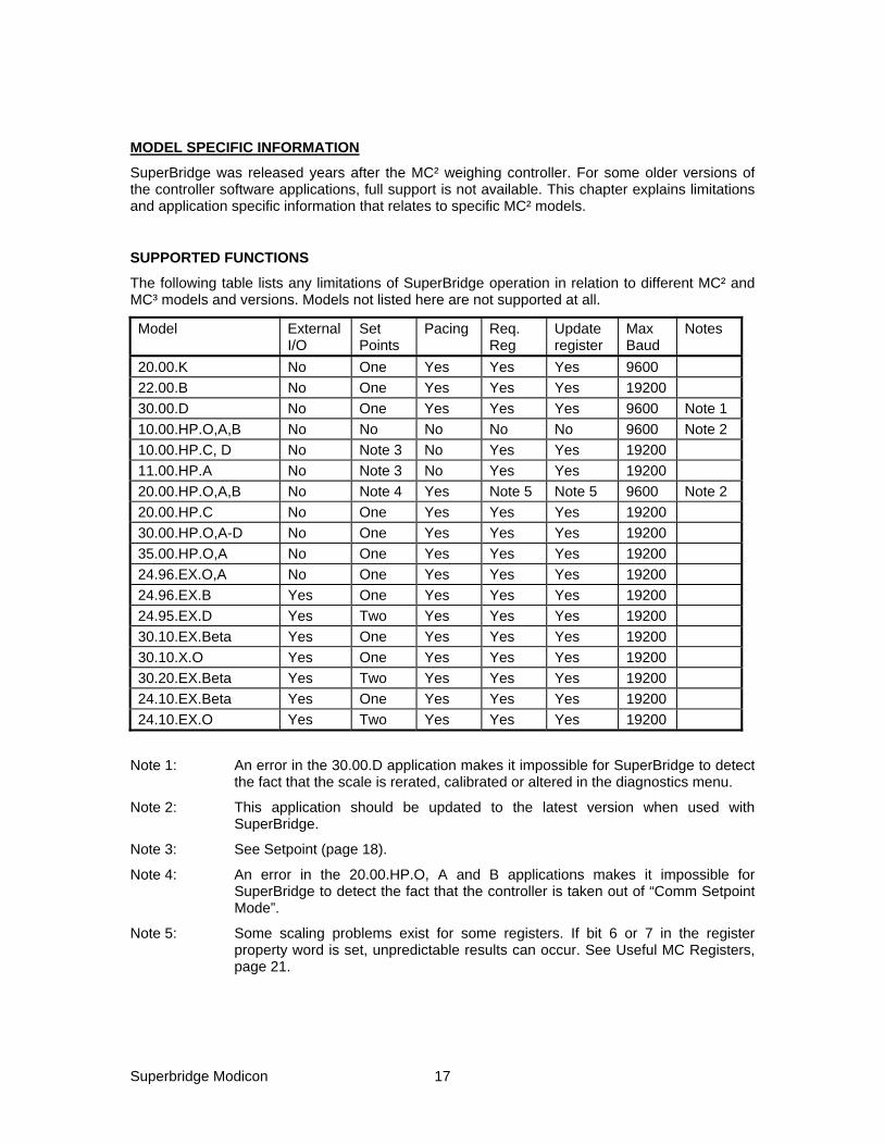
The following table lists any limitations of SuperBridge operation in relation to different MC² and MC³ models and versions. Models not listed here are not supported at all.
Model External I/O
Set Points
Pacing Req. Reg
Update register
Max Baud
Notes
20.00.K No One Yes Yes Yes 9600 22.00.B No One Yes Yes Yes 19200 30.00.D No One Yes Yes Yes 9600 Note 1 10.00.HP.O,A,B No No No No No 9600 Note 2 10.00.HP.C, D No Note 3 No Yes Yes 19200 11.00.HP.A No Note 3 No Yes Yes 19200 20.00.HP.O,A,B No Note 4 Yes Note 5 Note 5 9600 Note 2 20.00.HP.C No One Yes Yes Yes 19200 30.00.HP.O,A-D No One Yes Yes Yes 19200 35.00.HP.O,A No One Yes Yes Yes 19200 24.96.EX.O,A No One Yes Yes Yes 19200 24.96.EX.B Yes One Yes Yes Yes 19200 24.95.EX.D Yes Two Yes Yes Yes 19200 30.10.EX.Beta Yes One Yes Yes Yes 19200 30.10.X.O Yes One Yes Yes Yes 19200 30.20.EX.Beta Yes Two Yes Yes Yes 19200 24.10.EX.Beta Yes One Yes Yes Yes 19200 24.10.EX.O Yes Two Yes Yes Yes 19200
Note 1: An error in the 30.00.D application makes it impossible for SuperBridge to detect the fact that the scale is rerated, calibrated or altered in the diagnostics menu.
Note 2: This application should be updated to the latest version when used with SuperBridge.
Note 3: See Setpoint (page 18).
Note 4: An error in the 20.00.HP.O, A and B applications makes it impossible for SuperBridge to detect the fact that the controller is taken out of “Comm Setpoint Mode”.
Note 5: Some scaling problems exist for some registers. If bit 6 or 7 in the register property word is set, unpredictable results can occur. See Useful MC Registers, page 21.

Superbridge Modicon 18
PROCESS VALUE
The process value is, with the following exceptions, the feedrate, as displayed in the root node of the controller. The exceptions are:
11.00.HP Current Gross Weight, with high resolution.
35.00.HP Actual Batch Total for last batch weighed out.
SETPOINT
The setpoint value is, with the following exceptions, used as the feedrate setpoint, when the controller is in “Comm Setpoint” mode. The exceptions are:
10.00.HP The setpoint value is transferred to the High Feedrate alarm limit.
11.00.HP The setpoint value is transferred to the weight value for limit switch number 3.
35.00.HP The setpoint value is used as the batch setpoint when the controller is in “Comm Setpoint” mode.
GENERAL ALARMS
The General Alarm bits are mapped out according to the following table. Detailed information about the meaning of the alarms is available in the operations manual for the controllers. Warnings mapping in the MC³ models 24.10.EX, 30.10.EX and 30.20 EX depend on which inputs or outputs are qualified for warning. The bit order can be found by displaying the warning screen in the controller, when it has been configured
Controller Bit Meaning 20.00.K 1 Overflow 2 A/D Overrange 3 Auto-Tare Reject 4 Master Comm Lost 6 Display Failure 7 Display Failure 30.00.D 0 A/D Overrange 1 Hopper Empty 2 Slow Fill 3 Over Fill 4 Master Comm Lost 6 Display Failure 7 Display Failure 22.00 4 Master Comm Lost 6 Display Failure 7 Display Failure 10.00.HP 1 A/D Overrange 2 Auto-Tare Reject 3 Master Comm Lost 4 A/D Underrange 5 Display Failure 6 Display Failure
Controller Bit Meaning 7 HPAD Not Set-Up 8 Test OverFlow 11.00.HP 1 Scale Overload 2 Scale Underload 3 A/D Underrange 4 A/D Overrange 5 Bad Tare 7 HPAD Not Set 8 Bad Low Display 9 Comm Lost 20.00.HP 1 A/D Overrange 2 Auto-Tare Reject 3 Master Comm Lost 4 A/D Underrange 5 Display Failure 6 Display Failure 7 HPAD Not Set-Up 8 Test OverFlow 30.00.HP 1 Scale Overload 2 Scale Underload 3 A/D Underrange 4 A/D Overrange

Superbridge Modicon 19
Controller Bit Meaning 5 Slow Fill 6 Hopper Empty 7 HPAD Not Set 8 Bad Low Display 9 Comm Lost 11 Overfill 14 No HPAD Data 35.00.HP 1 Scale Overload 2 Scale Underload 3 A/D Underrange 4 A/D Overrange 5 Stable Timeout 6 Batch Timeout 7 HPAD Not Set 8 Bad Low Display 9 Comm Lost 10 Slow Fill 11 Fill When Batch 14 No HPAD Data 24.96.EX 1 Belt Load Over
Limit
Controller Bit Meaning 2 Belt Load Under
Limit 3 PCAD Near Zero 4 PCAD Near Full 5 Zero Tracking off
Limits 6 PCAD discrepancy,
load cells do not agree
7 PCAD not setup 8 Tachos do not
comply 9 Comm Lost 10 Remote Setpoint
Out Of Range 11 No Speed Detected 12 Analog input out of
range. 13 MC³ Display Not
Responding 14 No Data from
PCAD
DIGITAL I/O
The Digital I/O bits are mapped out according to the following table. Detailed information is available in the operations manual for the controllers. MC³ controllers are capable of mapping logical inputs and outputs to physical I/O points. The actual mapping must be examined using the ‘Digital Inputs’ and ‘Digital Outputs’ mapping screens on the controller.
Controller I/O Bit Meaning 20.00.K O 0 High Alarm O 1 Low Alarm O 2 Low Speed Cut off O 4 In Control O 6 General Alarm I 8 Soft Start I 9 Control Master
Reset 30.00.D O 0 High Alarm O 1 Low Alarm O 2 Filling O 3 Slow Fill O 4 In Control O 5 Feeder Running
Controller I/O Bit Meaning O 6 General Alarm I 8 Soft Start I 9 Control Master
Reset I 10 Remote Fill 22.00 O 0 High Alarm O 1 Low Alarm O 4 In Control O 6 General Alarm I 8 Soft Start I 9 Control Master
Reset 10.00.HP O 0 High Alarm O 1 Low Alarm

Superbridge Modicon 20
Controller I/O Bit Meaning O 2 Low Speed Cut off O 4 Calibration O 6 General Alarm 11.00.HP O 0 In Center Zero O 1 Scale Stable O 2 Print Complete O 3 Limit Switch 1 O 4 Limit Switch 2 O 5 Limit Switch 3 O 6 General Alarm I 8 Print String A I 9 Print String B I 10 Clear Sub-Total I 11 Tare 20.00.HP O 0 High Alarm O 1 Low Alarm O 2 Low Speed Cut off O 4 In Control O 6 General Alarm I 8 Soft Start I 9 Control Master
Reset 30.00.HP O 0 High Alarm O 1 Low Alarm O 2 Filling O 3 Slow Fill O 4 In Control O 5 Feeder Running O 6 General Alarm I 8 Soft Start I 9 Control Master
Reset
Controller I/O Bit Meaning I 10 Remote Fill 35.00.HP O 0 Fast Feed O 1 Fine Feed O 2 Fill valve open O 3 Batch Out Of
Tolerance O 4 Ready For Start O 5 Batch Complete O 6 General Alarm I 8 Remote Print I 9 Start Batch I 10 Stop / Reset Batch MC³ O 0 Rack 1 Output 1 O 1 Rack 1 Output 2 O 2 Rack 1 Output 3 O 3 Rack 1 Output 4 O 4 Rack 1 Output 5 O 5 Rack 1 Output 6 O 6 Rack 1 Output 7 O 7 Rack 1 Output 8 I 8 Rack 1 Input 1 I 9 Rack 1 Input 2 I 10 Rack 1 Input 3 I 11 Rack 1 Input 4 I 12 Rack 2 Input 1 I 13 Rack 2 Input 2 I 14 Rack 2 Input 3 I 15 Rack 2 Input 4
Note that the status of unused digital inputs in MCs are reported to the MC Digital I/O, IR:2,10,18.. (page 11), even if they are not used by the MC application. They can be used as remote inputs for the ladder logic.
INTERNAL STATE
Some cyclic controller applications have an internal state variable, useful for indication of what’s going on in. The state variable is numerical, and can not be used for bit monitoring.
30.00.HP
State Meaning 0 Check for fill requirement at startup
State Meaning 1 Prepare for normal feed

Superbridge Modicon 21
State Meaning 2 Wait for filter values to stabilize 3 Normal LIW feed 4 Prepare for a fill cycle 5 Filling 6 Check for auto-fill condition 7 Preparations after fill cycle 8 Stabilization time after filling
State Meaning 9 Prepare for normal feed after filling 10 Prepare for cleanout cycle 11 Run cleanout cycle to low weight 12 Run Cleanout cycle (time) after low
weight 12 Waiting for fill after cleanout complete
35.00.HP
State Meaning 0 Test for autofill 1 Stopped by button 7, "STOP BATCH" 2 Ready for start of new batch 3 Preparing for a batch 4 Prepare for mandatory wait before
stable 5 Wait before stable, before batching 6 Stable check before batching 7 Check if fast feed needed 8 Start fast feed 9 Fast feeding 10 Check if skip fine feed 11 Start fine feed
State Meaning 12 Fine feeding 13 Init wait after feed 14 Wait before stable after batching 15 Wait for stable after batching 16 Calc weight batched out so far 17 Calculate new preact 18 Prepare for filling 19 Arm timer before filling 20 Wait before fill 21 Wait for stability for filling 22 Start filling 23 Filling, check for overfill, done 24 Stop filling
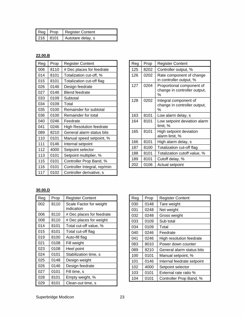
USEFUL MC REGISTERS
All MC² and MC³ applications contain a numbered table of parameters, called MC registers. They are useful in a SuperBridge environment for monitoring and control purposes. In the following sections, the content of the MC registers for the different applications are listed, along with the property word. The property word describes access rules, decimal places and scaling of the MC registers.
The property word has the following layout:
Bit 15..14 Internal storage format, according to the following table:
Bit 15 Bit 14 Storage format 0 0 long (32 bit integer) 0 1 char (8 bit integer) 1 0 int (16 bit integer) 1 1 float (32 bit IEEE floating point)
Bit 13..10 Not used
Bit 9 Set if the MC register is initialized to zero at controller cold start.

Superbridge Modicon 22
Bit 8 Set if the MC register is included in the MC register checksum, that is, is safely retained when the controller is powered down.
Bit 7..6 At least one of the bits are set if the MC register is scaled. SuperBrigde will unscale the MC register and convert it into a float.
Bit 5..4 Access mask. 00: Read and write permitted. 01: Read permitted. Write permitted if needle switch 1 is open on the display board, or the ‘Extended Access’ logical input is ON in the MC³. 10: Read access only. 11: No access.
Bit 3..0 Decimal place codes. 0..4: 0..4 decimal places, respectively. 5..9 according to the values in MC registers 005..009, respectively, with the exception of models 20.00.K and 22.00, where the number of decimal places for code 009 is found in MC register 170, and 30.00.D, where the number of decimal places for code 009 is found in MC register 134.
20.00.K
Reg Prop Register Content 002 8110 Scale Factor for load
indication 005 8110 # Dec places for speed 006 8110 # Dec places for feedrate 007 8110 # Dec places for belt length 008 8110 # Dec places for load 020 0107 Belt length 021 0148 Design load 026 0146 Design Feedrate 029 0105 Design belt speed 030 0148 Tare Load 031 0248 Net load 032 0248 Gross load 033 0109 Sub total 034 0109 Total 037 0205 Belt speed 039 0100 Tacho pulse counter 040 0246 Feedrate 041 0246 High resolution feedrate 083 8010 Power down counter 089 8210 General alarm status bits 118 0105 Internal speed setpoint 119 0101 Manual setpoint, % 120 0146 Internal feedrate setpoint 121 4000 Setpoint selector 122 0101 External rate ratio % 123 0101 Controller Prop Band, % 124 0100 Controller Integral, s/reset
Reg Prop Register Content 125 0102 Controller derivative, s 136 8202 Controller output, % 137 0202 Rate component of change
in controller output, % 138 0202 Proportional component of
change in controller output, %
139 0202 Integral component of change in controller output, %
163 8101 Low alarm delay, s 164 8101 Low setpoint deviation
alarm limit, % 165 8101 High setpoint deviation
alarm limit, % 166 8101 High alarm delay, s 170 8100 # Dec places for belt total 182 0106 High feedrate alarm limit 183 0106 Low feedrate alarm limit 184 0105 High speed alarm limit 185 0105 Low speed alarm limit 186 8100 Alarm mode selector 187 8100 Totalizer cutoff mode
selector 188 8100 Cutoff value, % 189 8101 Cutoff delay, s 210 8102 Allowed change in autotare,
% 212 8101 Min load for autotare, % 214 8100 Autotare enable selector
Superbridge Modicon 23
Reg Prop Register Content 216 8101 Autotare delay, s
22.00.B
Reg Prop Register Content 006 8110 # Dec places for feedrate 014 8101 Totalization cut-off, % 015 8101 Totalization cut-off flag 026 0146 Design feedrate 027 0146 Blend feedrate 033 0109 Subtotal 034 0109 Total 035 0100 Remainder for subtotal 036 0100 Remainder for total 040 0246 Feedrate 041 0246 High Resolution feedrate 089 8210 General alarm status bits 110 0101 Manual speed setpoint, % 111 0146 Internal setpoint 112 4000 Setpoint selector 113 0101 Setpoint multiplier, % 115 0101 Controller Prop Band, % 116 0101 Controller Integral, rep/min 117 0102 Controller derivative, s
Reg Prop Register Content 125 8202 Controller output, % 126 0202 Rate component of change
in controller output, % 127 0204 Proportional component of
change in controller output, %
128 0202 Integral component of change in controller output, %
163 8101 Low alarm delay, s 164 8101 Low setpoint deviation alarm
limit, % 165 8101 High setpoint deviation
alarm limit, % 166 8101 High alarm delay, s 187 8100 Totalization cut-off flag 188 8101 Totalization cutoff value, % 189 8101 Cutoff delay, % 202 0106 Actual setpoint
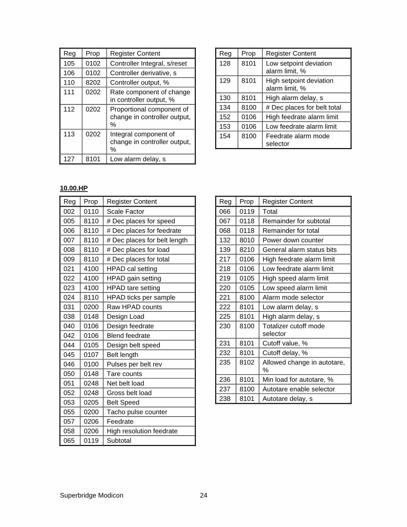
30.00.D
Reg Prop Register Content 002 8110 Scale Factor for weight
indication 006 8110 # Dec places for feedrate 008 8110 # Dec places for weight 014 8101 Total cut-off value, % 015 8101 Total cut-off flag 019 8100 Auto-fill flag 021 0108 Fill weight 023 0108 Heel point 024 0101 Stabilization time, s 025 0148 Design weight 026 0146 Design feedrate 027 0101 Fill time, s 028 8101 Empty weight, % 029 8101 Clean-out time, s
Reg Prop Register Content 030 0148 Tare weight 031 0248 Net weight 032 0248 Gross weight 033 0109 Sub total 034 0109 Total 040 0246 Feedrate 041 0246 High resolution feedrate 083 8010 Power down counter 089 8210 General alarm status bits 100 0101 Manual setpoint, % 101 0146 Internal feedrate setpoint 102 4000 Setpoint selector 103 0101 External rate ratio % 104 0101 Controller Prop Band, %
Superbridge Modicon 24
Reg Prop Register Content 105 0102 Controller Integral, s/reset 106 0102 Controller derivative, s 110 8202 Controller output, % 111 0202 Rate component of change
in controller output, % 112 0202 Proportional component of
change in controller output, %
113 0202 Integral component of change in controller output, %
127 8101 Low alarm delay, s
Reg Prop Register Content 128 8101 Low setpoint deviation
alarm limit, % 129 8101 High setpoint deviation
alarm limit, % 130 8101 High alarm delay, s 134 8100 # Dec places for belt total 152 0106 High feedrate alarm limit 153 0106 Low feedrate alarm limit 154 8100 Feedrate alarm mode
selector
10.00.HP
Reg Prop Register Content 002 0110 Scale Factor 005 8110 # Dec places for speed 006 8110 # Dec places for feedrate 007 8110 # Dec places for belt length 008 8110 # Dec places for load 009 8110 # Dec places for total 021 4100 HPAD cal setting 022 4100 HPAD gain setting 023 4100 HPAD tare setting 024 8110 HPAD ticks per sample 031 0200 Raw HPAD counts 038 0148 Design Load 040 0106 Design feedrate 042 0106 Blend feedrate 044 0105 Design belt speed 045 0107 Belt length 046 0100 Pulses per belt rev 050 0148 Tare counts 051 0248 Net belt load 052 0248 Gross belt load 053 0205 Belt Speed 055 0200 Tacho pulse counter 057 0206 Feedrate 058 0206 High resolution feedrate 065 0119 Subtotal
Reg Prop Register Content 066 0119 Total 067 0118 Remainder for subtotal 068 0118 Remainder for total 132 8010 Power down counter 139 8210 General alarm status bits 217 0106 High feedrate alarm limit 218 0106 Low feedrate alarm limit 219 0105 High speed alarm limit 220 0105 Low speed alarm limit 221 8100 Alarm mode selector 222 8101 Low alarm delay, s 225 8101 High alarm delay, s 230 8100 Totalizer cutoff mode
selector 231 8101 Cutoff value, % 232 8101 Cutoff delay, % 235 8102 Allowed change in autotare,
% 236 8101 Min load for autotare, % 237 8100 Autotare enable selector 238 8101 Autotare delay, s

Superbridge Modicon 25
11.00.HP
Reg Prop Register Content 003 0110 Scale Factor 005 8110 # Dec places for weight 006 8110 # Dec places for total 007 8110 # Dec places for enhanced
resolution 021 4110 HPAD cal setting 022 4110 HPAD gain setting 023 4110 HPAD tare setting 025 8110 HPAD fixed ticks per sample028 8210 External sync pulse counter 029 8110 External sync pulse divider 030 8110 Min ticks per samples
external sync 031 8110 Max ticks per samples
external sync 032 8110 External sync mode selector 038 0117 Design weight 039 0117 Overweight limit 040 0117 Underweight limit 041 0227 Absolute weight 042 0227 Gross weight 043 0227 Net weight 045 0227 Last stable weight
Reg Prop Register Content 046 0220 Raw HPAD counts 051 8220 Scale stable flag 055 0116 Total 056 0116 Subtotal 057 0117 Remainder for total 058 0117 Remainder for subtotal 076 4200 Printer transmitter status 082 0100 Item number for printout 083 0100 Item number increment 118 8010 Power down counter 124 8210 Actual alarm status 190 8110 Number of samples for
stability 191 0107 Permitted span for stability 192 0107 Weight interval for center
zero 230 0197 Zero tracking weight 231 0107 Max change in zero tracking
weight 232 0107 Max zero tracking weight
20.00.HP, 24.81.HP
Reg Prop Register Content 002 0110 Scale Factor 005 8110 # Dec places for speed 006 8110 # Dec places for feedrate 007 8110 # Dec places for belt length 008 8110 # Dec places for load 009 8110 # Dec places for total 021 4100 HPAD cal setting 022 4100 HPAD gain setting 023 4100 HPAD tare setting 024 8110 HPAD ticks per sample 031 0200 Raw HPAD counts 038 0148 Design Load 040 0106 Design feedrate 042 0106 Blend feedrate
Reg Prop Register Content 044 0105 Design belt speed 045 0107 Belt length 046 0100 Pulses per belt rev 050 0148 Tare counts 051 0248 Net belt load 052 0248 Gross belt load 053 0205 Belt Speed 055 0200 Tacho pulse counter 057 0206 Feedrate 058 0206 High resolution feedrate 065 0119 Subtotal 066 0119 Total 067 0118 Remainder for subtotal 068 0118 Remainder for total

Superbridge Modicon 26
Reg Prop Register Content 139 8210 General alarm status bits 186 0105 Internal speed setpoint 187 0101 Manual setpoint, % 188 0106 Internal feedrate setpoint 189 4110 Setpoint selector 190 0101 External rate ratio % 191 0206 Analog input feedrate
setpoint 192 0205 Analog input speed setpoint 193 0101 Controller Prop Band, % 194 0101 Controller Integral, rep/min 195 0102 Controller derivative, s 200 0202 Last controller raw output, %203 8101 Max controller acceleration,
%/s 204 8101 Max controller deceleration,
%/s 210 0202 Controller output, % 211 0202 Rate component of change
in controller output, % 212 0204 Proportional component of
change in controller output, %
213 0202 Integral component of change in controller output, %
Reg Prop Register Content 214 0101 Belt speed used for tare and
calibration procedures 217 0106 High feedrate alarm limit 218 0106 Low feedrate alarm limit 219 0105 High speed alarm limit 220 0105 Low speed alarm limit 221 8100 Alarm mode selector 222 8101 Low alarm delay, s 223 8101 Low setpoint deviation alarm
limit, % 224 8101 High setpoint deviation
alarm limit, % 225 8101 High alarm delay, s 230 8100 Totalizer cutoff mode
selector 231 8101 Cutoff value, % 232 8101 Cutoff delay, % 235 8102 Allowed change in autotare,
% 236 8101 Min load for autotare, % 237 8100 Autotare enable selector 238 8101 Autotare delay, s
30.00.HP
Reg Prop Register Content 003 0110 Scale Factor 005 8110 # Dec places for weight 006 8110 # Dec places for total 007 8110 # Dec places for enhanced
resolution 008 8110 # Dec places for feedrate 021 4110 HPAD cal setting 022 4110 HPAD gain setting 023 4110 HPAD tare setting 025 8110 HPAD fixed ticks per sample028 8210 External sync pulse counter 029 8110 External sync pulse divider 030 8110 Min ticks per samples
external sync 031 8110 Max ticks per samples
external sync
Reg Prop Register Content 032 8110 External sync mode selector 040 0117 Design Weight 041 0117 Overweight limit 042 0117 Underweight limit 043 0118 Design feedrate 045 0227 Gross weight 054 8220 Scale stable flag 055 0116 Total 056 0116 Subtotal 057 0117 Remainder for total 058 0117 Remainder for subtotal 112 8200 Calibration menu flag 113 8210 General alarm status bits 121 8110 Number of samples for
stability 122 0107 Permitted span for stability

Superbridge Modicon 27
Reg Prop Register Content 140 4110 Setpoint Selector 141 0112 External rate ratio % 142 0118 Internal setpoint 143 0111 Manual setpoint in % 144 0218 Analog input setpoint 145 0118 Communications setpoint 146 0118 Preliminary comm setpoint 147 0218 Actual (used) setpoint 150 0100 State variable for LIW
machine 151 8200 Manual fill request flag 165 8100 Alarm mode 166 0101 Low alarm delay 167 0101 High alarm delay 168 0118 Low rate alarm 169 0118 High rate alarm 170 0101 Low setpoint deviation % 171 0101 High setpoint deviation % 175 0117 Empty weight 176 0117 Heel Point 177 0117 Fill Weight
Reg Prop Register Content 200 0218 Actual Feedrate 205 0101 Controller Prop Band in
percent 206 0101 Controller repeats/minute 207 0102 Controller rate time in s 212 0202 Last Controller raw output in
percent 215 8101 Max Acceleration
percent/sec 216 8101 Max deceleration
percent/sec 217 0202 Controller output signal 218 0202 Rate component of change
in controller output 219 0204 Prop component of change
in controller output 220 0202 Integer component of
change in controller output 221 0100 Zero counts 226 0107 Calibration weight
35.00.HP
Reg Prop Register Content 003 0110 Scale Factor 005 8110 # Dec places for weight 006 8110 # Dec places for total 007 8110 # Dec places for enhanced
resolution 021 4110 HPAD cal setting 022 4110 HPAD gain setting 023 4110 HPAD tare setting 025 8110 HPAD fixed ticks per sample028 8210 External sync pulse counter 029 8110 External sync pulse divider 030 8110 Min ticks per samples
external sync 031 8110 Max ticks per samples
external sync 032 4110 External sync mode selector 038 0117 Design weight 039 0117 Overweight limit 040 0117 Underweight limit 042 0227 Gross weight
Reg Prop Register Content 043 0227 Net weight 045 0227 Last stable weight 046 0220 Raw HPAD counts 051 8220 Scale stable flag 055 0116 Total 056 0116 Subtotal 057 0117 Remainder for total 058 0117 Remainder for subtotal 075 4200 Printer transmitter status 082 0100 Item number for printout 083 0100 Item number increment 124 8210 Actual alarm status 190 8110 Number of samples for
stability 191 0107 Permitted span for stability 215 8100 Fill request flag 218 0197 Current batch total 223 0112 External rate ratio, % 224 0115 External batch setpoint 225 0115 Internal batch setpoint

Superbridge Modicon 28
Reg Prop Register Content 226 0115 External batch setpoint 227 0115 Comm batch setpoint 228 8100 Setpoint selector 229 0117 Batch tolerance 230 8100 Batch state variable 238 0117 Heel point 241 0117 Fill weight 242 0117 Current preact 243 0117 Max preact change 244 0117 Max preact absolute 245 0110 Preact adaptation, % 246 8101 Preact block selector
Reg Prop Register Content 247 0101 Wait time before checking
stability, s 248 0101 Max wait time for stability, s 249 0101 Max batch time, s 250 0101 Max fill time, s 251 8100 Ticks per sample when
feeding 252 8100 Ticks per sample default 254 0101 Fine feed desired time 256 0117 Min batch weight 257 0117 Max batch weight 259 0115 Previous batch total
24.96.EX
Reg Prop Register Content 003 C114 Scale Factor 005 8110 # Dec places for belt load 006 8110 # Dec places for Total 007 8110 # Dec places for belt length 008 8110 # Dec places for feedrate 009 8110 # Dec places for belt speed 020 C115 Design Belt Load 021 C118 Design Feedrate 022 C119 Design Speed 094 8010 Power Down Counter 096 8200 Actual Alarm Status 116 8200 Tacho 1 Counter 118 8200 Tacho 2 Counter 124 C100 Allowed Tacho Diff % 170 C221 Raw Load 173 C225 Net Load 175 C221 Raw PCAD count Average 176 C221 Raw PCAD #1 Counts 177 C221 Raw PCAD #2 Counts 180 0116 Current Total 181 0116 Current Subtotal
Reg Prop Register Content 184 C105 Totalization Cutoff Belt
Load 240 C105 Overload Alarm Limit 241 C105 Underload Alarm Limit 261 C229 Belt Speed 263 C117 Belt Length 264 C111 Tacho Pulses for one Rev 270 C101 Controller Gain Comp 271 C103 Controller Integral Comp 272 C102 Controller Derivative Comp 342 C115 Zero Load 354 C105 Current Zero Track Load 356 C115 Max permitted increment of
Zero Track Load 357 C115 Max Zero Track Load 372 C105 Chain Load for Calibration 441 0200 Analog Output 1 442 0200 Analog Output 2 445 0200 Analog Input 1
30.10.EX
Reg Prop Register Content 003 C114 Scale Factor 005 8110 # Dec places for weight 006 8110 # Dec places for Total 008 8110 # Dec places for feedrate
Reg Prop Register Content 020 C115 Design Weight 021 C118 Design Feedrate 022 C119 Design Speed 094 8010 Power Down Counter

Superbridge Modicon 29
Reg Prop Register Content 096 8200 Actual Alarm Status 166 C115 Weight Span for Stability 167 C225 Last Stable Weight 168 C110 # of Samples for Stability
Determination 170 C221 Raw Weight 172 C225 Net Weight 175 C221 Raw PCAD count Average 176 C221 Raw PCAD #1 Counts 177 C221 Raw PCAD #2 Counts 180 0116 Current Total 181 0116 Current Subtotal 245 C105 Overweight Alarm Limit 246 C105 Underweight Alarm Limit 265 C101 Controller Gain Comp
Reg Prop Register Content 266 C103 Controller Integral Comp 267 C102 Controller Derivative Comp 286 8110 # of Average Filter Slots 291 8110 # of Loss Slots 293 C115 Empty Weight 294 C115 Heel Point Weight 296 C115 Fill Point Weight 302 0110 Max AutoFill Time 303 0110 Max Time for Cleanout 336 C115 Zero Load from Zero
Procedure 342 C115 Calibration Weight 391 0200 Analog Output 1 392 0200 Analog Output 2 395 0200 Analog Input 1
24.10.EX
Reg Prop Register Content 003 C114 Scale Factor 005 8110 # Dec places for belt load 006 8110 # Dec places for Total 007 8110 # Dec places for belt length 008 8110 # Dec places for feedrate 009 8110 # Dec places for belt speed 020 C115 Design Belt Load 021 C118 Design Feedrate 022 C119 Design Speed 094 8010 Power Down Counter 104 8200 Fault bits 105 8200 Warning bits 116 8200 Tacho 1 Counter 118 8200 Tacho 2 Counter 124 C100 Allowed Tacho Diff % 170 C221 Raw Belt Load 173 C225 Net Belt Load 175 C221 Raw PCAD count Average 176 C221 Raw PCAD #1 Counts 177 C221 Raw PCAD #2 Counts 180 0116 Current Total 181 0116 Current Subtotal
Reg Prop Register Content 184 0105 Totalization Cutoff Belt
Load 238 C105 Overload Alarm Limit 240 C105 Underload Alarm Limit 261 C229 Belt Speed 263 C117 Belt Length 264 C111 Tacho Pulses for one Rev 270 C101 Controller Gain Comp 271 C103 Controller Integral Comp 272 C102 Controller Derivative Comp 342 C115 Zero Load 354 C105 Current Zero Track Load 356 C115 Max permitted increment of
Zero Track Load 357 C115 Max Zero Track Load 372 C105 Chain Load for Calibration 441 0200 Analog Output 1 442 0200 Analog Output 2 445 0200 Analog Input 1

Superbridge Modicon 30
DIAGNOSTIC SCREENS
If a VGA compatible monitor and a PC keyboard is connected to the SB host PC, several diagnostic screens are available. They are usable for verification, troubleshooting, checking ladder and MMI programming, and for editing data in the Integer Control (IC) and Float Control (FC) arrays. Note that with the exception of the Home Screen, there is a SB performance penalty associated with the diagnostic display. For all screens in this section, the following SUPERB.INI was used:
; SUPERB.INI ; 10-30-95/LTM Modicon Manual Example Setup [SIZES] ; Only one port supported in beta version ComPorts = 1 Controllers = 5 Segments = 6 [IRQ] ; Settings for COM1 PortVector = 0C PIDMask = 10 [PORT1] ; COM1, 19200 Baud UartBase = 3F8 DlabReg = 0006 [ADAPTER] SWInterrupt = 5D [MC3] Used = 0 [PLCDEFAULT] ;Default host controller DefaultPath = DM.1.0.0.0.0 [SEGMENT0] ;PLC addresses are offset 100 from SB DestAddress = 40101 [SEGMENT1] DestAddress = 40133 [SEGMENT2] DestAddress = 40161 [SEGMENT3] DestAddress = 40225 [SEGMENT4] ;First MC IR data SourceAddress = 40001 DestAddress = 40040 Elements = 8 TfrType = IR Path = DM.2.1.0.0.0 ;Path to secondary PLC [SEGMENT5] ;First MC FR data SourceAddress = 40061 DestAddress = 40125 Elements = 8 TfrType = FR Path = DM.2.1.0.0.0 ;Path to secondary PLC [DATASLAVE] Path = DS.1.0.0.0.0
• There are five MCs in this system; one of them, MC Index 3, is not used.
• SB reports to and is being controlled by a Quantum 140, at path DM.1.0.0.0.0.

Superbridge Modicon 31
• Data in the report files IR and FR for the first controller are also reported to a PLC at path DM.2.1.0.0.0. The PLC is turned off, to demonstrate errors in the MB+ communication.
• A Excel workbook is interrogating SB via MODLINK and a SA-85 adapter. One of the DDE links will cause an exception return from SB.

Superbridge Modicon 32
THE HOME SCREEN 1 SuperBridge Home Screen 2 3 Merrick - Modicon SuperBridge Time: Sun Jul 12 11:37:38 1995 4 Copyright (C) 1998 Merrick Industries Started: Sun Jul 12 11:35:10 1995 5 All Rights Reserved MCs: 5 6 Ver 1.10. Built Jul 5 1998, 14:04:50 Segments: 6 7 8 MC Status map 9 0: Run/30.00.HP.C Run/20.00.HP.C Run/30.00.HP.C Not Used 10 4: Run/22.00.B 12 13 MB+ Segments map 14 0: Run/40101 Run/40133 Run/40161 Run/40225 15 4: Err/40040 Err/40125 16 17 18 19 20 21 22 23 24 F2 F3 F10 25 MC Data MB+ Msgs Exit
This screen show overview status for SB. It is also the default and preferred screen during normal operations, since the SB performance penalty is minimal.
Displayed information:
Line Keyword Explanation 3..6 Left
Revision, copyright and build data for the SB software application.
3 Time: Current time in the SB host PC. 4 Started: The time in SB host PC at which SB was started. 5 MCs: Number of configured MCs. 6 Segments: Number of configured MB+ file copy segments. 8f MC Status
map Communication status and application models/versions for all configured MCs. Possible status are Run (running, no communication problems), Ofl (taken off-line), Not Used, Rev (communications reviving attempt in progress) and Err (Communication problems). Four MCs are shown per screen line.
11f MB+ Segments map
Communication status and first destination holding register number for all configured MB+ File Copy segments. Possible status are Run (running, no communication problems) and Err (Communication problems). Four segments are shown per screen line.
Function keys:
F2 Switch to MC Data Screen (page 33)
F3 Switch to MB+ Slave Messages Diagnostics Screen (page 42)
F10 Stop SB and return to the DOS prompt

Superbridge Modicon 33
MC DATA SCREEN 1 MC Data, Controller Index 0 2 3 Number of MCs connected 5 Comm Errors logged 0 4 MC in use (1 = YES, 0 = NO) 1 Fatal Comm Errors 0 5 MC WatchDog (0.1 s ticks) 200 State Machine Index 12 6 MC Revive Time (ms) 20000 MC Model/Version 30.00.HP.C 7 MC Controller Number 1 MC Current Status Running 8 9 IR Elems 40001 Stat MCSt DI/O LRMS RDON RERR RRES XOUT 10 Pending: 0100 0003 0378 0260 0000 0000 0000 0000 11 Completed: 0000 0000 0000 0000 0000 0000 0000 0000 12 IC Elems 40041 FTag Stg1 Stg2 Stg3 MCCT RINT EXIN 13 Pending: 002D 0090 0093 00D9 0000 0002 0000 14 Completed: 0000 0000 0000 0000 0000 0000 0000 15 Edit Ints (hex): [ ][ ][ ][ ][ ][ ][ ] 16 FR Elems 40076 FTag Stg1 Stg2 Stg3 17 Pending: 34.307 0.000 1000.000 4.960 18 FR Elems 40084 ProcessVal Total ReqFResult RSRV 19 Pending: 1004.000 2625.390 0.000 0.000 20 FC Elems 40156 SetPoint ReqFParam Sec SetPoint 21 Pending: 1000.000 0.000 0.000 22 Edit Floats: [ ][ ][ ] 23 24 F1 F2 F3 F6 F7 F10 25 Home Screen MC Diags MB+ Msgs Next MC Prev MC Exit
The MC Data Screen shows status information and current array data for one MC. It is also possible to edit the local SB content of the two control arrays IC and FC. If segment copy is enabled for these arrays, editing is meaningless, since the edited data item will be overwritten by the next segment read.
Line Keyword Explanation 1 MC Controller index for data currently displayed 3 Number of
MCs connected
Number of configured MCs.
4 In Use A 0 indicates the data for the MC is allocated, but never used. There is normally no controller at all with this index.
5 MC WatchDog:
The value of the local MC WatchDog timer in 0.1 s. See WatchDog (page 45)
6 MC Revive Time
How often (in ms) SB will attempt to re-establish communication with a MC that has had a fatal (non-recoverable) communication error. See ReviveTime (page 45)
7 MC Controller Number
The local MC controller Number setting. See MC Communication Parameters (page 7) and ControllerNumber (page 44)
3 Comm Errors logged
How many recoverable (non-fatal) communication error that have occurred for this MC since SB was started.
4 Fatal Comm Errors
How many fatal (non-recoverable) communication error that have occurred for this MC since SB was started.
5 State Machine index
Used for telephone support. This value rapidly scans through a seemingly random number of values.
6 MC Model/Version
MC application program model and version. “Unknown” if the no successful communication has taken place with the MC or if the model

Superbridge Modicon 34
Line Keyword Explanation and version is unknown to SB (not supported)
7 MC Current Status
Possible status are Running (running, no communication problems), off-line (taken off-line), NotUsed, Reviving (communications reviving attempt in progress) and CommErr (Communication problems).
9-11 IR Elems Integer Report data from the IR array.. See Integer Report (page 10). Hexadecimal representation. “Pending” means actual current data in SB. Completed means the last data successfully copied to a PLC.
12-15
IC Elems Integer Control data from the IC array. See Integer Control Array (page 12). Hexadecimal representation. “Pending” means actual current data in SB. Completed means that the action required by the data has been initiated. It is possible to edit IC elements, using tab/backtab to move the cursor to the field to edit, enter digits (Hex) and hit return.
16-19
FR Elems Floating Point Report data from the FR array. See Float Report Array (page 14). “Pending” means actual current data in SB. Note that the holding register reference increments with two for every float. The first float, “FTag” starts at holding register 40041. The second, “Stg1” starts at 40043, etc.
12-15
FC Elems Floating Point Control data from the FC array. See Float Control (page 15). “Pending” means actual current data in SB. It is possible to edit FR elements, using tab/backtab to move the cursor to the field to edit, enter digits (including minus sign and decimal point) and hit return. Note that the holding register reference increments with two for every float.
Function keys:
F1 Switch to The Home Screen (page 32)
F2 Switch to MC Combined Diagnostic Screen (page 35)
F3 Switch to MB+ Slave Messages Diagnostics Screen (page 42)
F6 Switch to the MC with the next controller index
F7 Switch to the MC with the previous controller index
F10 Stop SB and return to the DOS prompt

Superbridge Modicon 35
MC COMBINED DIAGNOSTIC SCREEN 1 MC Combined Diagnostic Port 0 Controller Index 0 2 3 RxPtr: 0 RxData: 30000000000000000006d 4 TxPtr: 6 TxData: 2d6a 5 Used 1|State 3|LastErr 0|FatalErrs 1|LastFatErr -7 6 ParErrs 0|OvrErrs 1|FrameErrs 0|BreakErrs 0|BufOverrs 0 7 Timeouts 6|CsumErrs 0|BusyErrs 0|AccessErrs 0|BadFncErrs 0 8 BadataErrs 0|FormatErrs 0|RFrmErrs 0|RLimErrs 0|NotSupErrs 0 9 ErrErrs 0|CurrSlave 1|CurrTelegram 7|TimerTicks 0|RetryCount 0 10 MaxRetries 2|PortIndex 0|ActiveMC 1| | 11 12 Used 1|State 0|TgmState 26|SlowState 29|TagIndex 1 13 LastAck 0|AccessNakOK 0|Rescaled 0|TimeOut 6|WatchDog 200 14 IdNum 38|VerNum 67|ModelIdx 17|Pacing 0|RegProp 0000 15 RegNum 150|Port 0|StartChar A|EndChar D|ControllerNr 1 16 Errors 3|LastErr -7|FatalErrs 0|LastFatalErr 0|DownTime 0 17 RevTime 20|InPuts 0003|OutPuts 0078|Alarms 0260|NumRegs 313 18 RQRobin 3|SetDlsa 1|SetDlsc 1|LastSp 6.395|KeyLocked 0 19 Decimal Points 2 2 3 0 0 |RegValue 3|Scalef 21885 20 Total 1119.3000|ProcV 994.0000| 21 Bezel [ 994] [Feedrate g/min ] YLed:40 GLed:FD 22 23 24 F1 F2 F3 F4 F5 F6 F7 F10 25 Home Screen A-B Copy MC Data Next Port Prev Port Next MC Prev MC Exit
This screen shows communications related data for one communications port (Serial port in the SB host PC) and for one MC. The upper part of the screen shows port data, the lower MC data. Since SB currently only supports one serial port, the port index is always 0. It is mostly used by Merrick for telephone support and for SB internal trouble-shooting. Some entries are useful for general trouble trouble-shooting. They are listed here:
Line Keyword Explanation 5 Used A 0 indicates the data for the port is allocated, but never used. 5 Last Err Last communication error encountered on this port. See Numerical Error
Values (page 37) 5 FatalErrs How many fatal (non-recoverable) communication error that have
occurred for this port since SB was started. 5 LastFatErr Last fatal (non-recoverable) communication error encountered on this
port. See Numerical Error Values (page 37) 6-8 Individual statistics for each possible communication error on the port.
See Numerical Error Values (page 37) 10 ActiveMC There is at least one MC on this port that is active, that is, not Off-line or
Not Used. 12 Used A 0 indicates the data for the MC is allocated, but never used. There is
normally no controller at all with this index. 12 State Communication status. The numerical value of “MC Current Status” in
MC Data Screen (page 33) 12 TgmState Used for telephone support. This value rapidly scans through a
seemingly random number of values. See also MC Data Screen (page 33)
13 WatchDog The value of the local MC WatchDog timer in 0.1 s. See WatchDog (page 45)

Superbridge Modicon 36
Line Keyword Explanation 14 IDNum The numerical value of the application model. Displayed if retrieved,
even if the specific application is not supported by SB. 14 VerNum The numerical value of the application version. Displayed if retrieved,
even if the specific version is not supported by SB. 14 ModelIdx A 0 here indicates that there is no support for this application/version
combination. 14 Pacing The controller is in pace mode. See also Bit 7 in MC Control Word,
IC:4,11,18.. (page 10) 15 ControllerNr The local MC controller Number setting. See MC Communication
Parameters (page 7) and ControllerNumber (page 45) 16 Errors How many recoverable (non-fatal) communication error that have
occurred for this MC since SB was started. Same as “Comm Errors logged” in MC Data Screen (page 33)
16 LastErr Last communication error encountered on this MC. See Numerical Error Values (page 37)
16 FatalErrs How many fatal (non-recoverable) communication errors that have occurred for this port since SB was started.
16 LastFatalErr Last fatal (non-recoverable) communication error encountered on this MC. See Numerical Error Values (page 37)
16 DownTime How many ms this MC has waited for revival attempt after a fatal communication error.
17 RevTime How often (in ms) SB will attempt to re-establish communication with a MC that has had a fatal (non-recoverable) communication error. See ReviveTime (page 45)
17 InPuts Hexadecimal representation of the MC physical inputs. See Digital I/O (page 19)
17 OutPuts Hexadecimal representation of the MC physical outputs. See Digital I/O (page 19)
17 Alarms Hexadecimal representation of the MC Alarm bits. See General Alarms (page 18)
17 NumRegs The highest possible MC register number in this MCs model/version. See Useful MC Registers (page 21)
18 SetDlsa Number of attempts to download a setpoint to an MC 18 SetDlsc Number of successful downloads of a setpoint to an MC 18 LastSp Value of the last downloaded setpoint to the MC 18 Leylocked 1 if keyboard/touchpad is locked, else 0 19 DecimalPoints Current values of the five MC decimal point settings. 20 Total Current value of the MC Total. See Total, FR:5,13,21.. (page 15) 20 ProcV Current value of the MC Process Value. See Process Value,
FR:4,12,20.. (page 15) 21 Bezel For a MC², First field is a copy of what is displayed in the upper (seven
segment) display. Second field is a copy of what is displayed in the lower (alphanumeric) display.
21 YLed Hexadecimal representation of the state of the yellow LEDs in the MC² front panel.
21 GLed Hexadecimal representation of the state of the green LEDs and square red light in the MC² front panel.

Superbridge Modicon 37
Function keys:
F1 Switch to The Home Screen (page 32)
F2 Switch to MB+ Segment Copy Diagnostic Screen (page 38)
F3 Switch to MC Data Screen (page 33)
F4 Switch to port data for the next serial port (No effect in this version)
F4 Switch to port data for the previous serial port (No effect in this version)
F6 Switch to the MC with the next controller index
F7 Switch to the MC with the previous controller index
F10 Stop SB and return to the DOS prompt
Numerical Error Values
This is a list of the numerical values that can appear in a communication error field:
Value Name Explanation 2 OvrErr Serial communications Overrun error 4 ParErr Serial communications parity error 8 FrameErrs Serial communications framing error 16 BreakErr Serial communications break condition detected -1 FormatErr The MC detected an telegram with a bad format -2 BusyErr The MC can’t perform the service requested in the telegram at this time -3 AccessErr The MC can’t perform the service requested in the telegram because of
access restrictions -4 BadataErr The MC can’t perform the service requested in the telegram because
parameter(s) are out of the legal limit -5 PowUp The controller has been rebooted and needs comm re-initialization -6 BadFncErr The requested function is unknown by this MC -7 TimeOuts SB timed out waiting for a MC response -11 RFrmErr Bad format in MC return telegram -12 RLimErr Parameter(s) in MC return telegram are out of the legal limit -13 NotSupErr The MC Model/Version combination is not supported by SB.

Superbridge Modicon 38
MB+ SEGMENT COPY DIAGNOSTIC SCREEN 1 MB+ Segment Copy Diagnostics 2 3 ErrCall: 4 ErrMsg: 5 Segments 6|CurrSeg 1|SWInterrupt 5D|DefaultPath DM.1.0.0.0.0 6 Paths 2|ExitFlag 0|ResetRet 0| 7 8 Seg SAddr DAddr El Typ Sta Path Exc Accepts Rejects Time Last Completed 9 0 40001 40101 40 IR Run 0 0 52 0 0 Oct 30 13:33:58 1995 10 1 40041 40133 35 IC Run 0 0 51 0 0 Oct 30 13:33:57 1995 11 2 40076 40161 40 FR Run 0 0 51 0 0 Oct 30 13:33:58 1995 12 3 40156 40225 15 FC Run 0 0 51 0 0 Oct 30 13:33:58 1995 13 4 40001 40040 8 IR Err 1 0 0 50 0 Never 14 5 40061 40125 8 FR Err 1 0 0 50 0 Never 15 16 17 18 19 20 21 22 23 24 F1 F2 F3 F4 F5 F10 25 Home Screen MB+ Paths MC Diags Next Page Prev Page Exit
This screen shows status for some central MB+ communication parameters and for each segment defined for MB+ segment copy. See SB Configuration for Segment Copy (page 9) The ErrCall field in line 3 gives a textual representation of the last error encountered while attempting to communicate over the DH+ network. Parameters in the segment list are:
Parameter Explanation Seg Segment number. “N” in [SegmentN] Section (page 47) SAddr First source holding register address in the SB array involved in the segment copy.
See SourceAddress (page 47). This address must be an element in IR, IC, FR or FC.
DesAddr First destination holding register address in the target PLC involved in the segment copy. See DestAddress (page 47)
El Number of elements in the segment. Must be less than 100 for IR and IC, and less than 50 for FR and FC. See Elements (page 47)
Typ Data type for the file transfer. PLC Holding Register Array Specification (page 10). Possible values are IR, meaning integers copied to the PLC; IC, meaning integers copied from the PLC; FR, meaning floats copied to the PLC and FC, meaning floats copied from the PLC.
Sta Status for the segment copy process. Possible values are “Run” and “Err”. Path Index for the path used for this segment copy process. Path information is
available in MB+ Path Diagnostics Screen (page 40). Exc Exception code received for the last segment copy attempt. Possible values are 0:
no problems, 1: the MB+ function used for segment copy (Preset Multiple Registers or Read Holding Registers) is not supported by the PLC, 2: invalid register address in the target PLC, 3: invalid data field in the MB+ telegram, 4: the target PLC is not on-line and 5: the path to the target PLC could not be opened. Exception code 5 normally indicates a problem with the local SA-85 adapter.
Accepts Number of successful segment copy transactions since SB was started.
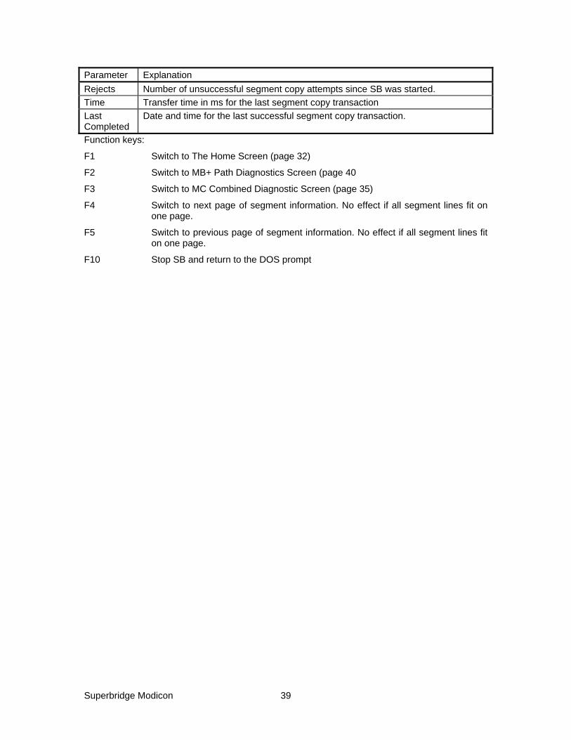
Superbridge Modicon 39
Parameter Explanation Rejects Number of unsuccessful segment copy attempts since SB was started. Time Transfer time in ms for the last segment copy transaction Last Completed
Date and time for the last successful segment copy transaction.
Function keys:
F1 Switch to The Home Screen (page 32)
F2 Switch to MB+ Path Diagnostics Screen (page 40
F3 Switch to MC Combined Diagnostic Screen (page 35)
F4 Switch to next page of segment information. No effect if all segment lines fit on one page.
F5 Switch to previous page of segment information. No effect if all segment lines fit on one page.
F10 Stop SB and return to the DOS prompt

Superbridge Modicon 40
MB+ PATH DIAGNOSTICS SCREEN 1 MB+ Paths Diagnostics 2 3 ErrCall: 4 ErrMsg: 5 Segments 6|CurrSeg 2|SWInterrupt 5D|DefaultPath DM.1.0.0.0.0 6 Paths 2|ExitFlag 0|ResetRet 0| 7 8 Path Statistics O Seg S Snd Rec Exc Snds Rcvs Opens Touts NList 9 0:DM.1.0.0.0.0 Y 2 1 0 0 0 6630 6733 1 103 0 10 1:DM.2.1.0.0.0 Y 5 1 0 18 4 113 53049 114 52936 113 11 12 NCB Statistics Name CO RE TY RT ST ISnds IRecs OSnds ORecs 13 0:DM.00.00.00.00.00 95 0 1 0 14 0 0 0 0 14 1:DM.00.00.00.00.00 B0 0 2 0 14 0 0 0 0 15 16 17 18 19 20 21 22 23 24 F1 F2 F3 F10 25 Home Screen MB+ Msgs MB+ Copy Exit
This diagnostic screen is available as a part of the beta test program. It may go away in the production release. It deals mostly with internal MB+ driver diagnostics and SB internal error statistics counters. Some useful fields:
Line Keyword Explanation 5 Segments Number of specified segments for segment copy. See Segments (page
44). 5 CurrSeg The index of the segment that is currently being subject to a copy
transaction. 5 SWInterrupt The SA85 adapter software interrupt used. ([2], page 9). 5 DefaultPath The default SB path used for processing segment copy. 6 Paths Number of paths used for master processing. There is one path per
target PLC. 8-10 Path Statistics Path index and path string defined for the segment. 8-10 O Y if the path is open. N if the path is closed. An open path does not
necessarily indicate that the PLC is responding. 8-10 Seg Segment index for the segment currently being processed for this path. 8-10 S The state of the internal SB slave processor state machine. 8-10 Snd Result of the last attempt to send a MB+ telegram from SB for this path.
0 indicates no problems. Other values are listed in [2], pages 102..104. 8-10 Rec Result of the last attempt to receive a MB+ telegram to SB for this path.
0 indicates no problems. Other values are listed in [2], pages 102..104. 8-10 Exc Last exception code for this path. 0 indicates no problems. Other
possible values are 1: the MB+ function used for segment copy (Preset Multiple Registers or Read Holding Registers) is not supported by the PLC, 2: invalid register address in the target PLC, 3: invalid data field in the MB+ telegram, 4: the target PLC is not on-line and 5: the path to the target PLC could not be opened. Exception code 5 normally indicates a problem with the local SA-85 adapter.
8-10 Snds Number of attempts to send a MB+ telegram from SB for this path.

Superbridge Modicon 41
Line Keyword Explanation 8-10 Rcvs Number of attempts to receive a MB+ telegram to SB for this path. 8-10 Opens How many times the path has been opened. Should normally be 1. A
high number indicates communication problems. 8-10 Touts Number of attempts to receive a MB+ telegram to SB for this path,
resulting in a time-out condition. 8-10 NList Number of attempts to send a MB+ telegram to SB for this path,
resulting in a no-response condition, indicating that the target PLC is not on-line.
Lines 12-14 contains no useful information.
Function keys:
F1 Switch to The Home Screen (page 32)
F2 Switch to MB+ Slave Messages Diagnostics Screen (page 42)
F3 Switch to MB+ Segment Copy Diagnostic Screen (page 38)
F10 Stop SB and return to the DOS prompt

Superbridge Modicon 42
MB+ SLAVE MESSAGES DIAGNOSTICS SCREEN 1 MB+ Slave Messages Diagnostics 2 3 Messages On|ErrorMsgs On|Status Run|LastMsg Oct 30 16:39:31 1995 4 LastRec 0|LastSnd 0|LasExc 0|Path DS.1.0.0.0.0 5 OkPMs 550|OkPSs 0|OkRMs 3235|Snds 3925|Rcvs 13784 6 BadPMs 140|BadPSs 0|BadRMs 0|NoSu 0|NoLi 0 7 8 RH 40076(FR:000) - 40091(FR:007), 16 registers 9 RH 40041(IC:000) - 40047(IC:006), 7 registers 10 RH 40156(FC:000) - 40161(FC:002), 6 registers 11 PM 40158(FC:001) - 40159(FC:001), 2 registers 12 PM 40156(FC:000) - 40157(FC:000), 2 registers 13 PM Exc 2 01 10 00 4B 00 02 04 00 00 .. 14 RH 40001(IR:000) - 40008(IR:007), 8 registers 15 RH 40076(FR:000) - 40091(FR:007), 16 registers 16 RH 40041(IC:000) - 40047(IC:006), 7 registers 17 RH 40156(FC:000) - 40161(FC:002), 6 registers 18 RH 40001(IR:000) - 40008(IR:007), 8 registers 19 RH 40076(FR:000) - 40091(FR:007), 16 registers 20 RH 40041(IC:000) - 40047(IC:006), 7 registers 21 RH 40156(FC:000) - 40161(FC:002), 6 registers 22 PM Exc 2 01 10 00 4B 00 02 04 00 00 .. 23 24 F1 F2 F3 F4 F5 F6 F7 F10 25 Home Screen MC Data MB+ Paths Stop Tgm Start Tgm Stop Er Start Er Exit
This screen shows status for some central MB+ communication parameters and for the last 15 slave messages received by SB. See Slave Messages Processing Specification (page 16). The upper part of the screen contains some status information:
Parameter Explanation Messages “Off” or “On” Indicates if good messages are logged to the lower part of the
screen or not. See F4 and F5 below. ErrorMsgs “Off” or “On” Indicates if invalid messages are logged to the lower part of the
screen or not. See F6 and F7 below. Status “Run” or “Err” indicating the operational status of the message processor Last Msg Time and date for the last slave message processed. LastRec Result of the last attempt to receive a MB+ telegram to SB. 0 indicates that a
message was received with no problems. 5 indicates that no message was waiting to be processed. Other values are listed in [2], pages 102..104.
LastSnd Result of the last attempt to send a MB+ telegram from SB. 0 indicates no problems. Other values are listed in [2], pages 102..104.
LastExc Last exception code returned. 0 indicates no problems. Other possible values are 1: the MB+ function requested is not supported by the SB, 2: invalid register address in SB, 3: invalid data field in the MB+ telegram, 4: the requesting PLC went off-line and 5: the slave path in SB could not be opened. Exception code 5 normally indicates a problem with the local SA-85 adapter.
Path The SB internal path for processing slave messages. OkPMs Number of ‘Preset Multiple Registers’ messages successfully processed. OkPSs Number of ‘Preset Single Register’ messages successfully processed. OkRMs Number of ‘Read Holding Registers’ messages successfully processed. Snds Number of attempts to send a MB+ telegram from SB. Rcvs Number of attempts to receive a MB+ telegram to SB. BadPMs Number of ‘Preset Multiple Registers’ messages unsuccessfully processed. BadPSs Number of ‘Preset Single Register’ messages unsuccessfully processed.

Superbridge Modicon 43
Parameter Explanation BadRMs Number of ‘Read Holding Registers’ messages unsuccessfully processed. NoSu Number of messages received not supported by SB, generating exception 01 NoLi Number of attempts to send a MB+ response telegram from SB, resulting in a
no-response condition, indicating that the querying PLC went off-line.
The lower part of the screen shows data for the last 16 received slave messages. The row beneath the last message in blank. The screen does not scroll. A row for a good message contains what kind of message received, see Slave Messages Processing Specification (page 16), the range of holding registers and the number of holding registers. A row for a bad message contains the kind of message, the exception code generated and the beginning of the message body itself, in hex. The second byte is the function code: 03 for Read Holding Registers, 06 for Preset Single Register and 10 for Preset Multiple Registers.
In this example (Row 13 and 22), a Preset Multiple Register message was received. The message body layout is described in detail in [2], page 179. Note that the message description in this specification starts with the second byte in the message body. The first holding register requested is 004B hex, 75 decimal, which corresponds to holding register 40076. This holding register in the FR array, and consequently read only. An exception code 2 (invalid address for this PLC) was generated.
Function keys:
F1 Switch to The Home Screen (page 32).
F2 Switch to MC Data Screen (page 33).
F3 Switch to MB+ Path Diagnostics Screen (page 40).
F4 Stop logging good messages
F5 Start logging good messages
F6 Stop logging error messages
F7 Start logging error messages
F10 Stop SB and return to the DOS prompt
Superbridge Modicon 44
CONFIGURATION
SB is completely configurable via the configuration file, SUPERB.INI. The file can be edited using a text editor. It is loaded every time the SB application is started up. The file is divided into sections with a format similar to Windows initializations files.
[SIZES] SECTION
The sizes section deals with the size of the SB application, such as number of connected MCs.
ComPorts
Depending on how many MCs are connected, one or more RS-422 serial ports are used for the MC connections. If more than one port is used, a multiport adapter is installed in the SB host PC. This entry specifies the number of ports used. Default is 1.
Controllers
This entry specifies the number of connected MCs. Default is 5.
Segments
If automatic segment copy is desired, this entry must have a non-zero value. It describes how many copy segments that are to be active. In the default case of five MCs or less, this value is normally four, since four different arrays are involved: IR, IC, FR and FC. If more than five MCs are connected each individual array must be divided up in segments, normally one segment per six MCs. Default is calculated as
( )[ ]Segments 4 INT Controllers 4 / 6= ⋅ + ,
where INT is the integer part of the argument. See also SB Configuration for Segment Copy (page 9). To completely disable segment copy, set this entry to zero.
[IRQ] SECTION
This section deals with hardware and interrupt properties of the serial ports used for MC communications. The ports are assumed to share one interrupt.
PortVector
This is the interrupt vector number for the port in hex. Use 0B for COM2 (default) or 0C for COM1.
PIDMask
This is the mask word used for the Priority Interrupt Decoder interrupt request mask bit. Use 08 for COM2 (default) and 10 for COM1.
[PORTN] SECTIONS
SB communicates with MCs using a single COM port (COM 1..4) or using a multiport adapter. The multiport adapter can have up to four serial ports, on different I/O addresses, and must share a common IRQ line. This section specifies properties for the communication ports used for each port. N can be 0, 1, 2 or 3, but must be less than the ComPorts entry in the [Sizes] Section, page 44.

Superbridge Modicon 45
UartBase
Base address for the UART, port N, hexadecimal. Default is 2F8 for section [Port0], which is the base address for COM2 in a normal PC. COM1 normally has base address 3F8. Sections [Port1]..[Port3] does not have a default; the base address for those ports have to be specified when a multiport adapter is used.
DLABReg
This entry indirectly specifies the baud rate used for each port. It is possible to run different ports with different baud rates. Old MC² applications supports baud rates up to 9,600, newer up to 19,200, and MC³ can communicate up to 38,400 baud. The entry is in hexadecimal format. Default is 0C for 9,600 baud. Use the following table:
Baud Rate DLABReg value
4,800 0018 9,600 000C 19,200 0006 38,400 0003
Retries
This is the number of times SB will try to recover from a MC communication error. Default is 2. Increase this number if the communication lines are very long and noise is present. There is a performance penalty associated with high values.
[MCN] SECTIONS
These sections define properties associated with a particular MC. N is the controller index, which start at 0 and end at Controllers (page 44) minus one.
Used
Valid entries are 0 and 1. 1 is default. A 0 means the controller with index N is never to be used. This is useful when data must be allocated for a growing number of controllers, and the MO holding register references must remain the same.
Timeout
This is the time in PC ticks (Approx. 52 ms) that SB waits for responses from MCs. Default is 6.
WatchDog
An MC can be set to generate a general alarm if SB communication becomes silent for a set time. This time (in 0.1 s increments) is set here. Default is 200, corresponding to 20s. If this value is set to zero, the MC will never generate a general alarm for lost SB communication.
ReviveTime
If a fatal communication error occurs for a MC, SB will ignore it (to avoid performance degradation), and later attempt to re-establish communications. This is the time (in ms) that SB will wait. Default is 20000, corresponding to 20s.
ControllerNumber
The controller number is set in the MC. MCs on the same port may must all have different controller number. Default is the controller index (N) plus one.

Superbridge Modicon 46
Port
The index of the serial port to which the controller in connected. If a single serial port is used, do add a port entry. Valid entries are 0..ComPorts - 1.
[MODATA] SECTION
For applications where there is no PLC-based control file, initial data can be set for every element in the IC and FC arrays. This is typically done for MC register tags, setpoints and other control information. Default is that all elements of IC and FC are initialized to zero. Entries in the section have the format
Element = Value
Element must be a valid holding register number within IC or FC. Values are hexadecimal for IC and floating point numbers (including decimal points and minus signs) for FC. Example:
[MODATA] 40041 = C8 ; Actual weight fast tagged in controller index 0 40156 = 12.33 ; Setpoint for controller index 0 40145 = 2 ; Set “download setpoint” bit for controller index 0
If segment copy is configured for IC and FC, the data that are initialized will probably be overwritten.
[PLCDEFAULT] SECTION
In this section, global defaults can be set for all register copy segments. It is to avoid having to specify every parameter for every segment. Normally, this is the only place that segment parameters have to be specified.
DefaultPath
The default PLC path for the target PLC. The path string must always start with DM. if no Path entry exist in the [SegmentN] Section (page 47), this path will be used. Default is DM.1.0.0.0.0.
MCPerSegment
This in the number of MCs that is associated with a set of copy segments. Default (and maximum) is 6. For a 14 MC installation, the segments will be arranged as follows with a MCPerSegment setting of 4 and 6, receptively:
MCPerSegment = 4 MCPerSegment = 6 Segment First Holding
Register Elements Segment First Holding
Register Elements
0 40001 32 0 40001 48 1 40113 28 1 40113 42 2 40211 32 2 40211 48 3 40435 12 3 40435 18 4 40033 32 4 40049 48 5 40141 28 5 40155 42 6 40275 32 6 40307 48 7 40447 12 7 40453 18 8 40065 32 8 40097 16 9 40169 28 9 40197 14 10 40339 32 10 40403 16

Superbridge Modicon 47
MCPerSegment = 4 MCPerSegment = 6 Segment First Holding
Register Elements Segment First Holding
Register Elements
11 40459 12 11 40471 6 12 40097 16 13 40197 14 14 40403 16 15 40471 6
[SEGMENTN] SECTION
This section contains entries for the segment copy map. N is the segment index. A default table of segment information is established when SB starts up. The segment composition can be completely overwritten in this section. See example in Diagnostic Screens (page 30). Some parameters in the default segment layout are settable with entries in the [PLCDefault] Section (page 46) The following rules apply for the default segment table:
SourceAddress First element associated with the first controller in this segment. See MCPerSegment (page 46). There are four segments per set of MCs
DestAddress Same as SourceAddress
Elements Depends on the MCPerSegment setting. Using the default (6), 48 for IR, 42 for IC, 48 for FR and 18 for FC.
TfrType IR, IC FR or FC, depending on what array the segment belongs to.
Path According to the entry in DefaultPath in the [PLCDefault] Section (page 46).
TimePeriod 1000, corresponding to 1 s.
SourceAddress
This is the holding register reference in SB of the first element for segment N. It must be an existing element in within the R, IC FR or FC arrays.
DestAddress
This is the holding register reference for the first element of the segment N in the target PLC It must be an existing holding register, set aside for the SB segment, not necessarily equal to the internal SB holding register. See Allocating Holding Registers (page 8).
Elements
Number of elements for segment N. Max 100 for IC and IR, 50 for FC and FR. Every element in FR and FC takes two holding registers.
Path
Path to the target PLC for segment N. Different segments may have different target PLCs. See example in Diagnostic Screens (page 30). Normally the target host PLC carrying the control arrays (IC and FC) is set up as DefaultPath is the [PLCDefault] Section (page 46). Other PLCs have their paths defined here. Note that the path string must start with ‘DM.’. For information about MB+ paths, consult [1], page 141.

Superbridge Modicon 48
TimePeriod
This entry is the time, in ms, between file copy attempts. Default is 1000, one attempt every second.
MBPTimeout
Max allowed time for a MB+ transaction to complete on 0.5 s increment. Default is 20, corresponding to 10 s.
TfrType
Specifies the what kind of segment copy that shall take place:
IR Copy integer data from SB to PLC IC Copy integer data from PLC to SB FR Copy floating point data from SB to PLC FC Copy floating point data from PLC to SB
[DATASLAVE] Section
Path
The complete path string for the internal slave message processor. Default is DS.1.0.0.0.0.
[ADAPTER] Section
SWInterrupt
The software interrupt used for the SA85 communications adapter. Deafult is 5C. See [2], page 9. If a Netbios compatible network is operational, 5D may be a better choice. Note that the PC configuration file CONFIG.SYS has to be altered accordingly. See Modify PC configuration, page 5.

Superbridge Modicon 49
REFERENCES
[1] Modicon Modbus Plus Network, Planning and Installation Guide. Modicon Publication 890 USE 100 00, October 1994
[2] Modicon IBM Host Based Devices User’s guide Modicon Publication GM-HBDS-001 Rev G, January 1995
[3] Modicon 984 Programmable Controller Systems Manual Modicon Publication GM-0984-SYS Rev. B, May 1991


