&EPA United States Office of Environmental Protection Emergency and Agency Remedial Response Superfund Record of Decision: EPAlRODIR10-921045 September 1992 PB93-964615 111111111 111lI111I11111111 1111111 IIII US DOE Idaho National Engineering Lab (Operable Unit 2), ID REPRODUCED BY U,S. DEPARTMENT OF COMMERCE NATIONAL TECHNICAL INFORMATION SERVICE SPRINGFIELD, VA 22161
Transcript
&EPA
United States Office ofEnvironmental Protection Emergency andAgency Remedial Response
US DOE Idaho NationalEngineering Lab (OperableUnit 2), ID
REPRODUCED BYU,S. DEPARTMENT OF COMMERCE
NATIONAL TECHNICALINFORMATION SERVICESPRINGFIELD, VA 22161
NonCE
The appendices listed in the index that are not found in this document have been removed at the request ofthe issuing agency. They contain materiaJ which supplement, but adds no further applicable information tothe content of the document. All supplemental material is. however. contained in the administrative recordfor this site.
PAGE EPA/ROD/R10-92/0454. TIueandSubtiue SUPERFUND RECORD OF DECISION 5. Report Date
US DOE Idaho National Engineering Laboratory 09/28/92(Operable Unit 2), ID 6-Third Remedial Action - Subsecruent to follow
7. AUlhor(a) a. f'erlonning Organization Rapt. No.
9. Perlonning Or911inlzation Name and AddreA 10. ProjectlTuklWort Unit No.
11. Contnet(C) or Grant(G) No.
(e)
(G)
12. Sponaoring Organization Name and Adc1re118 13. Type of Raport & Period Cownd
U.S. Environmental Protection Agency 800/000401 M Street, S.w.Washington, D.C. 20460 14.
15. Supplementary NOlefl
PB93-96461516. Abstract (Limit: 200 words)
The 890-square mile Idaho National Engineering Laboratory (INEL) is located 32 mileswest of Idaho Falls, Idaho. The site, established in 1949, is operated as a nuclearreactor technology development and waste management facility by the U.S. Department ofEnergy. Land use in the area is predominantly industrial and mixed use. The siteoverlies a sole source Class I aquifer, the Snake River Plain Aquifer. A10-mile-square area within the INEL complex, referred to as Test Area North (TAN) , wasbuilt in the 1950's to support the Aircraft Nuclear Propulsion Program sponsored by theU.S. Air Force and Atomic Energy Commission. Within TAN, the Technical SupportFacility (TSF-OS) injection well was used to dispose of industrial and sanitary wastesand wastewaters from 1953 to 1972 . Types of wastes disposed of in the well includedlow-level radioactive and process wastes, corrosive wastewater, ignitable wastes,chromium, lead, and mercury. Contaminants, including TCE, PCE, tritium, andstrontium-90, were first detected above MCLs in the ground water in 1987. Based onthese results, a RCRA Corrective Action Program was SUbsequently developed to addressground water contamination at TAN, which included installation of an air spargingsystem in the water supply tank at the TSF to ensure that organic contaminantconcentrations remain below regulatory levels. Ground water sampling and monitoring
(See Attached Page), 7. Document Analysis L Descriptors
Record of Decision - US DOE Idaho National Engineering Laboratory (Operable Unit 2) , IDThird Remedial Action - Subsequent to followContaminated Medium: gwKey Contaminants: VOCs (PCE, TCE) , metals (lead), radioactive materials
EPA/ROD/R10-92/045US DOE Idaho National Engineering Laboratory(Operable Unit 2), IDThird Remedial Action - Subsequent to follow
Abstract (Continued)
continued through 1990, and contaminated sludge from the lower 55 feet of the TSF-05injection well was removed and analyzed in 1990. Currently, the TSF-05 injection well isclosed securely and locked, and the well head has been sealed against surface waterintrusion. The INEL site is divided into 10 Waste Area Groups (WAGs). Two RODs in 1991and 1992 addressed an interim remedy for Warm Waste Pond sediment in WAG 2 and an interimremedy for unexploded ordnance and soil contamination in WAG 10. This ROD provides aninterim remedy for ground water contamination near the TSF-05 injection well (WAG 1) .The primary contaminants of concern affecting the ground water are VOCs, including TCEand PCE; metals, including lead; and radioactive materials.
The selected remedial action for this site includes pumping the contaminated ground waterfrom the injection well and treating the ground water onsite using filtration to removesuspended solids, followed by air stripping and carbon adsorption to remove organics, andion exchange to remove inorganics and radionuclides; modifying the existing TAN onsitedisposal pond to receive treated ground water and ensure that it does not exceeddischarge limits; transporting any spent carbon offsite to a permitted facility forregeneration; installing two additional ground water monitoring wells within thecontaminant plume; monitoring air emissions; and implementing administrative andinstitutional controls, including ground water use restrictions. The estimated capitalcost for this remedial action is $7,715,000, with a total O&M cost of $3,194,000 for 2years.
PERFORMANCE STANDARDS OR GOALS:
Chemical-specific ground water clean-up goals, which are based on SDWA MCLs, and includeTCE 5 ug/l; PCE 5 ug/l; lead 50 ug/l; and strontium-90 300 pCi/l. Air emissions alsowill be monitored and will not exceed state air quality standards, which includeTCE.OOOS1 lb/hr; PCE 0.013 lb/hr; lead 1.5 ug/m 3 ; and strontium-90 10 mrem/yd.
September 1992
IOAHO OEI'IORTl.IENT0> HEAlTH AND wElF'NlE
DIVISION OFENVIRONMENTAL QUALITY
•Idaho
NationalEngin~~ring
Laboratory Record of Decision..... f,oI ..~
-- _ .., ..... :rl~ ..... ,!
Technical Support Facility (TSF) Injection Well (TSF-05) andSurrounding Groundwater Contamination (TSF-23)
•
Operable Unit 1-07AWaste Area Group 1
Idaho National Engineering LaboratoryIdaho Falls, Idaho
•
•
•
DECLARATION OF THE RECORD OF DECISION
Site Name and Location
TSF Injection Well (TSF-05) and Surrounding Groundwater Contamination (TSF-23)Operable Unit (OU) 1-07AWaste Area Group 1Idaho National Engineering LaboratoryIdaho Falls, Idaho
Statement of Basis and Purpose
1his decision document presents the selected interim remedial action for the Technical Support Facility(TSF) Injection Well (TSF-05), and the groundwater surrounding the injection well (TSF-23) as described in theFederal Facility Agreement/Consent Order (FFA/CO). 1his action was chosen in accordance with the Comprehensive Environmental Response, Compensation, and Uability Act (CERCLA) as amended by the SuperfundAmendments and Reauthorization Act (SARA), and to the extent practicable, the National Oil and HazardousSubstances Pollution Contingency Plan (NCP). This decision is based on the Administrative Record for the site.
The State of Idaho Department of Health and Welfare (IDHW) concurs with the selected remedy.
Assessment of the Site
Actual or threatened releases of hazardous substances from this site, if not addressed by implementing theresponse action selected in this Record ofDecision (ROD), may present an imminent and substantial endangerment to public health, welfare,Qf;the environment.
Description of the Selected Remedy
'Ibis interim action is intended to prevent further degradation of the groundwater by reducing contaminants near the TSF-05 injection well and in the surrounding groundwater. The selected remedy will also not beinconsistent with nor preclude the"implementation of the final response action scheduled to be determined in1994:
The major components of the selected remedy include:
• Extract contaminated groundwater from the TSF-05 injection well and perhaps nearby groundwatermonitoring weUs that are capable of capturing contaminated groundwater.
• Install two groundwater monitoring wells within the contaminant plume to monitor the effectiveness ofthe interim action. These wells may also be used as extraction wells to expedite the removal of contaminated groundwater.
• Install on-site groundwater treatment facilities to reduce contaminants of concern in the extracted groundwater to prescribed performance standards. The selected treatment system is air stripping, carbon adsorp-
• tion, and ion exchange.
iii
•Monitor the groundwater contaminant plume and the extraction/treatment system during groundwaterextraction activities to track the effectiveness of the system and to ensure that performance standards areachieved.
Mod.ify the existing Test Area Nor-ill (TAN) d.isposal pond to receive the treated groundwater and ensurethat discharge water quality does not further degrade the underlying Snake River Plain Aquifer abovemaximum contaminant levels.
Implement administrative and institutional controls that supplement engineering controls and minimizeexposure to releases of hazardous substances during remediation.
Statutory Determinations
This interim action is protective of human health and the environment, complies with·Federal and Stateapplicable or relevant and appropriate requirements for this limited-SCOpe action, and is cost-effective. Althoughthis interim action is not intended to fully address the statutory mandate for permanence and treatment to themaximum extent practicable. this interim action utilizes treatment and thus is in furtherance of that statutorymandate.
Although this is an interim action, it is intended to prevent further degradation of the groundwater untilthe final remedy for au 1-07 is selected. Because this action does not constitute the final remedy for au 1-07.the statutory preference for remedies that employ treatment that reduces toxicity, mObility, or volume as a princi- •pal element, although partially addressed in this remedy, will be addressed by the final response action. Subse-quent investigations are planned to address the potential threats posed by the conditions at OU 1-07.
Because this remedy will result in hazardous substances remaining on site above health-based levels, areview will be conducted to ensure that the remedy continues to provide adequate protection of human health andthe environment within two years after commencement of the remedial action. Because this is an interim actionROD, review of these sites and of this remedy will be continuing while developing final remedial alternatives forau 1-07.
•iv
• Signature sheet for the foregoing Operable Unit 1-07A TSF-05 injection well and surrounding groundwaterinterim action at the Test Area North at the Idaho National Engineering Laboratory Record of Decision betweenthe United States Department of Energy and the United States Environmental Protection Agency, withconcurrence by the Idaho Department of Health and Welfare.
., ,_' I
" II
•
•
Augustine A Pitrolo DateManagerDepartment ofEnergy, Idaho Field Office
v
• Signature sheet for the foregoing Operable Unit 1-07A TSF-05 injection well and surrounding groundwaterinterim action at the Test Area North at the Idaho National Engineering Laboratory Record of Decision betweenthe United States Depamnent of Energy and the United States Environmental Protection Agency. withconcurrence by the Idaho Department of Health and Welfare.
•
•
( ,,lQ/1U\_ Ci- <-'~c!.(~~,-
Dana RasmussenRegional Administrator. Region 10Environmental Protection Agency
SEP 2 8 1992
Date
vi
.-._.-
•
•
Signature sheet for the foregoing Operable Unit 1-07A TSF-OS injection well and surrounding groundwaterinterim action at the Test Area North at the Idaho National Engineering Laboratory Record of Decision betweenthe United States Department of Energy and the United States Environmental Protection Agency. withconcurrence by the Idaho Department of Health and Welfare.
"
I .."..... _..
Richard Donovan DateDirectorIdaho Department of Health and Welfare
. .~....
vii
•
•
•
CONTENTS
DECLARAnON OF THE RECORD OF DECISION illAcronyms ix
DECISION SUMMARY1. Site Name, Location and Description 12. Site History and Enforcement Actions 33. Highlights of Community Panicipation 64. Scope and Role of the Operable Unit 85. Summary of Site Characteristics 86. Summary of Site Risks 197. Description of Alternatives 208. Summary of Comparative Analysis of Alternatives 229. Selected Remedy " 2710. Statutory Detennination 3211. Explanation of Significant Differences 34
Appendix A - Responsiveness Summary '; " '" A-lAppendix B - Public Comment/Response List B-lAppendix C - Administrative Record Index C-l
TABLES
2-1. Facilities suspected of using the TSF-05 well for waste disposal .42-2. Curies released to the TSF-C5 injection well (by nuclide) (1959 to August 1972) 52-3. Concentration of groundwater contaminants of concern 65-1. 'Groundwater monitoring well data 125-2. Maximum detected concentrations of contaminants detected by the USGS
in groundwater samples at TAN 1987-1989 175-3. Contaminant concentration in TSF-05 injection well sludge 186-1. Contaminants of concern, thier respective MCLs, and risk-based concentrations 208-1. Comparative evaluation of alternatives " 248-2. Cost breakdown for alternatives 269-1. Waste treatment, storage, and disposal options for investigation-
derived, laboratory, and treatment process wastes 299-2. Interim performance standards 31
FIGURES
1-1. Test Area North at the Idaho National Engineering Laboratory I1-2. Facilities at the Test Area North 25-1. Hydrogeological profile of the Test Area North 95-2. Plan view of Test Area North showing the location of cross-section B-B' 95-3. Groundwater monitoring wells at the Test Area North 10
viii
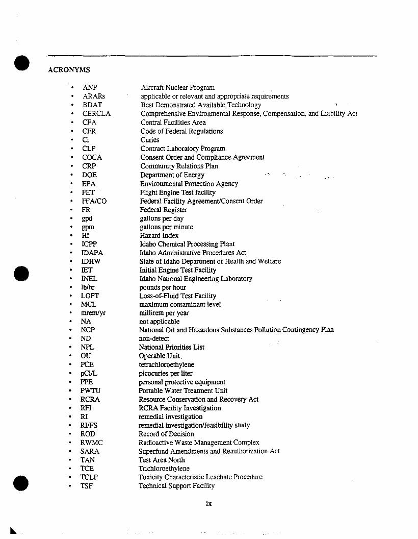
• ACRONYMS
• ANP Aircraft Nuclear Program• ARARs applicable or relevant and appropriate requirements
BDAT Best Demonstrated Available TechnologyCERCLA Comprehensive Environmental Response, Compensation. and Liability ActCFA Central Facilities Area
• CFR Code of Federal Regulations• Ci Curies• CLP Contract Laboratory Program• COCA Consent Order and Compliance Agreement• CRP Community Relations Plan• DOE Department of Energy .~ .-.
• EPA Environmental Protection Agency• FET Right Engine Test facility• FFA/CO Federal Facility Agreement/Consent Order• FR Federal Register• gpd gallons per day• gpm gallons per minute• HI Hazard Index
ICPP Idaho Chemical Processing Plant• IDAPA Idaho Administrative Procedures Act• IDHW State of Idaho Department of Health and Welfare
• • IET Initial Engine Test Facility• INEL Idaho Nationa! Engineering Laboratory
lblhr pounds per hour• LOFT Loss-of-Fluid Test Facility
MCL maximum contaminant level• mrem/yr millirem per year
NA not applicable• NCP National Oil and Hazardous Substances Pollution Contingency Plan• ND non-detect• NPL National Priorities List• OU Operable Unit.• PCE tetrachloroethylene• pCi/L picocuries per liter• PPE personal protective equipment• PWTU Portable Water Treannent Unit• RCRA Resource Conservation and Recovery Act• RFI RCRA Facility Investigation• RI remedial investigation• RIlFS remedial investigation/feasibility study• ROD Record ofDecision• RWMC Radioactive Waste Management Complex• SARA Superfund Amendments and Reauthorization Act• TAN Test Area North• TCE Trichloroethylene
• TCLP Toxicity Characteristic Leachate Procedure• TSF Technical Support Facility
ix
USGSVOCWAGWERFWRRTF~glgm
~gIL
~glm3
United States Geological SurveyVolatile Organic CompoundWaste Area GroupWaste Experimental Reduction FacilityWater Reactor Research Test Facilitymicrograms per grammicrograms per litermicrograms per cubic meter
x
•
•
•
• DECISION SUMMARY
Introduction
The Idaho National Engineering Laboratory (INEL) was proposed for listing on the National Priorities List(NPL) on July 14, 1989 (54 Federal Register [FR] 29820). The listing was proposed by the United StatesEnvironmental Protection Agency (EPA) under the authorities granted EPA by the Comprehensive EnvironmentalResponse,Compensation, and Liability Act (CERCLA) of 1980 as amended by the Superfund Amendments andReauthorization Act (SARA) of 1986. The final rule that listed the INEL on the NPL was published on November21, 1989, in 54 FR 44184.
1. SITE NAME, LOCATION AND DESCRIPTION
The INEL is an 89O-square mile Federal facility operated by the United States Departtnent ofEnergy (DOE)(Figure 1·1). The primary missions ofthe INEL are nuclear reactor technology development and waste management.
Current land use at the lNEL is classified as industrial and mixed use by the United States Bureau of LandManagement and the lNEL has been designated as a National Environmental Research Park. The developed areawithin the INEL is surrounded by a 500 square mile buffer zone used for cattle and sheep grazing. All livestock arekept approximately 12 miles away from the TestArea North (TAN) complex. However, wildspecies such as antelope.are allowed to roam freely within and across the INEL boundaries. These wild species are prevented from enteringoperational areas at the INEL by security fences.
To 91adc100c
•INEL
TERRI:TON
02~68MILESI I I ,- II I I
o ~ 8 12 KILOMETERS
Test Area North
CFA Central Facilities AreaRWMC Radioactive Waste Management FacilityWERF Waste Experimental Reduction Facility
R921195
~~=::!::::"__";T~OI~d&'lo Fo..
Big SouthernBUIle~
•
• Figure I-I. Test Area Northat the Idaho National Engineering Laboratory.
•Approximately 7,700 people are employed at the INEL, with an estimated 650 employed at the TAN. Thenearest off-sitepopulations are in the cities of: Terreton and Mud Lake (12 miles east); Arco (22 miles west); Blackfoot(38 miles southeast); Idaho Falls (49 miles east); and Pocatello (67 miles southeast).
The INEL has semidesen characteristics with hot summers and cold winters. Normal annual precipitation is9.1 inches per year, with estimated evapotranspiration rates of 6 to 9 inches per year. Twenty distinctive vegetationcover types have been identified at the INEL. Big sagebrush. the dominant species, covers approximately 80 percentofthe area. The varietyofhabitats on the INEL suppon numerous species ofreptiles, birds. and mammals. Underlyingthe INEL are a series of silicic and basaltic lava tlows and relatively minor amounts of sedimentary interbeds. Thebasalts immediately beneath the site are relatively flat and covered with 20 to 30 ft ofalluvium. The Snake River PlainAquifer underlies the INEL and has been designated a sole source aquifer pursuant to the Safe Drinking Water Act.
The TAN complex is located in the nonhero portion of the INEL and extends over an area of approximately10 square miles. Access to this area is controlled with fences and security patrols. TAt\[ was built in the early 19505to suppon the Aircraft Nuclear Propulsion Program sponsored by the United States Air Force and the Atomic EnergyCommission. The Technical Suppon Facility (TSP) is centrally located within TAN (Figure 1-2), and consists ofseveral experimental andsupport facilities for conductingresearch anddevelopmentactivitiesonreactorperformance.The TSF covers an area ofapproximately 2,200 ft by 1,500 ft and is surrounded by a security fence. Located insideofthe TSF fence are 38 buildings and 44 associated structures. The TSF-05 injection well is located in the southwestcomer of TSF. Located outside of the fence are parking areas, a helicopter landing pad, rubble piles, a gravel pit,groundwater monitoring wells, surface drainage wells, and a number of roads.
....
TSF-05 Injection well
•
•
T920555
TAN·2 production well
TAN-' production well
.................--.
1000 2000 3000 Plant North!
Scale," feel '\~~~~o
1000 SOO 0-Figure 1-2. Facilities at the Test Area North.
2
•
•
•
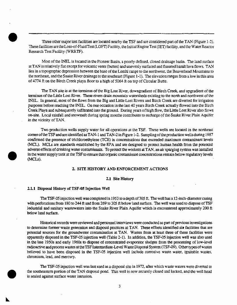
Three other major test facilities are located nearby the TSF and are considered part of the TAt\! (Figure 1-2).These facilities are the Loss-of-FluidTest(LOFI') Facility, the Initial Engine Test (lET) facility. and the Water ReactorResearch Test Facility (WRRTF).
Most of the lNEL is located in the Pioneer Basin, a poorly defined, closed drainage basin. The land surfaceat TAN is relatively flat except for volcanic vents (buttes) and unevenly surfaced and fissured basalt lava flows. TANlies in a topographic depression between the base of the Lemhi range to the northwest, the Beaverhead Mountains tothe northeast, and the Snake River drainage to the southeast (Figure 1-1). The elevation ranges from a low in this areaof 4774 ft on the Birch Creek playa floor to a high of 5064 ft on top of Circular Butte.
The TAN site is at the terminus of the Big Lost River, downgradient of Birch Creek, and upgradient of theterminus of the Little Lost River. These rivers drain mountain watersheds existing to the north and northwest of the1NEL. In general, most of the flows from the Big and Little Lost Rivers and Birch Creek are diverted for irrigationpurposes before reaching the INEL. On one occasion in the last 40 years Birch Creek actually flowed into the BirchCreek Playa and subsequently infiltrated into the ground During years ofhigh flow, the Little Lost River also flowson-site. Local rainfall and snowmelt during spring months contributes to recharge of the Snake River Plain Aquiferin the vicinity ofTAN.
Two production wells supply water for all operations at the TSF. These wells are located in the northeastcorneroftheTSF andare identifiedas TAN-I andTAN-2inFigure 1-2. Samplingoftheproduction wells during 1987confirmed the presence of trichloroethylene (TCE) in concentrations that exceeded maximum contaminant levels(MCL). MCLs are standards established by the EPA and are designed to protect human health from the potentialadverse effects ofdrinking water contaminants. To protect the workers at TAN, an air sparging system was installedin the water supply tank at the TSF to ensure that organic contaminant concentrations remain below regulatory levels(MCLs).
2. SITE mSTORY AND ENFORCEMENT ACTIONS
2.1 Site History
2.1.1 Disposal History of TSF-05 Injection Well
TheTSF-OS injection well was completed in 19S3 to adepth of30S ft. The well has a 12-inch-diametercasingwith perforations from 180 to 244 ft and from 269 to 30S ft below land surface. The well was used to dispose ofTSFindustrial and sanitary wastewaters into the Snake River Plain Aquifer which is encountered approximately 200 ftbelow land surface.
Historical records were reviewed and personnel interviews were conducted as part ofprevious investigationsto determine former waste generation and disposal practices at TAN. These efforts identified sa facilities that arepotential sources for the groundwater contamination at TAN. Wastes from at least three of these facilities wereapparently disposed in the TSF-QS injection well (Table 2-1). In addition, the TSF-QS injection well was also usedin the late 19S0s and early 1960s to dispose of concentrated evaporator sludges from the processing of low-levelradioactive andprocess wastes at theTSFIntermediate-Level WasteDisposal System(TSF-Q9). Other types ofwastesbelieved to have been disposed in the TSF-05 injection well include corrosive waste water, ignitable wastes.chromium, lead, and mercury.
The TSF-OS injection well was last used as a disposal site in 1972. after which waste waters were diverted tothe southeastern portion of the TAN disposal pond. This well is now securely closed and locked, and the well headis sealed against surface water intrusion.
3
•Table 2-1. Facilities suspected of using the TSF·05 well for waste disposal.
ShopLocation Function Waste Streama Time Frame TreatmenrlStorageiDisposal
TAN-604 Maintenance shop Organics and other chemicals 1956-1972 TSF-05 injection well viasewage plant
TAN-607 Chemical cleaning Corrosive liquids (acids and 1955-1972 TSF-05 injection wellroom (pipe laundry) caustics, but drained separately)
a. Accurate disposal and usage records for these materials are not available.
Previous investigations do not provide definitive information on the volumes oforganic wastes disposed tothe TSF-05 injection well or the specific processes by which they were generated. However, radioactivity releasedto the TSF-oS injection well can be estimated. The Radioactive Waste Management Information System containsestimates of curies by nuclide released to the TSF-CS injection well for the period of 1971 through August 1972(Table 2-2, column 2). Records regarding radioactivity released prior to 1971 are not as accurate. Estimates suggestthe total radiation released to the TSF-oS injection well from 1959 to 1971 was approximately45 curies (Ci); however •information on the distribution by nuclide during this time period is not available. A rough approximationof nuclidedistribution from 1959 to 1971 was calculated in Table 2-2 (column 3) assuming the same distribution as known for1971 through August 1972, and a total release of 45 Ci. -
Potential sources ofgroundwater contamination at TAN, other than the TSF-05 injection well are not part ofthis interim action. These other potential sources will be investigated as part ofthe Waste Area Group r:wAG)-widegroundwater Remedial InvestigatioIl!Feasibility Study (RIIFS) [Operable Unit (aU) 1-o7BJ or the comprehensiveWAG 1 RIIFS (aU 1-10).
2.1.2 Previous Groundwater Investigations
..,.iI1
Contaminants in the TAN groundwater were first detected in April 1987. During groundwater samplingactivities, TeE was detected in a sample collected for volatile organic compound (VOC) analyses from TSFproduction well TAN-I. SUbsequent sampling ofboth production wells (TAN-I andTAN-2 inFigure 1-2) for VOCsduring September and November 1987 confirmed the presence of TCE in both wells and also identifiedtetracbloroethyl~ne (PCE) in well TAN-I. Inaddition. independentgroundwater sampling atTAN was performedbythe USGS in 1987 and 1988. Results from these investigations indicate that well TSF-Q5 and a nearby observationwell (USGS-24, Figure 5-3) were contaminated with TCE and PeE at concentrations in excess ofMCLs. Samplesfrom well TSP-05 and the two production wells (TAN-} andTAN-2) werealso tested for seleetedradionuclides duringthese sampling efforts. Tritium and Strontium-90 were detected at concentrations in excess ofMCLs in samples fromwell TSF-05. Cesium-137. cobalt-60, americium-241, and plutonium were also detected in well TSF-QS; however,there are no MCLs for these analyres.
On the basis of the results from these early sampling efforts, a Resource Conservation and Recovery Act(RCRA) Corrective Action Program was developed to address groundwater contamination at TAN. One of the firstactions initiated was the installation ofan air sparger in the water supply system in 1989 to keep organic contaminant
4
•
• Table 2-2. Curies released to the TSF-05 injection well (by nuclide) (1959 through August 1972).
Nuclide Reponed Curies Released Estimated Curies Released Estimated Total Curies Released(1971 and 1972) (1959-1970) . ~.~ ..
Cesium-134 4.6 x 10⁻³ 2.4 x 10⁻² 2.9 x 10⁻²
Cesium-137 2.2 x 10⁻² 1.2 x 10⁻¹ 1.4 x 10⁻¹
Strontium-90 8.6 x 10⁻³ 4.6 x 10⁻² 5.4 x 10⁻²
Tritium 8.5 44.7 53.2
Unidentified alpha 1.0 x 10⁻³ 5.5 x 10⁻³ 6.6 x 10⁻³
Unidentified beta
and gamma 8.5 x 10⁻³ 4.5 x 10⁻² 5.4 x 10⁻²
Yttrium-90 8.6 x 10⁻³ 4.6 x 10⁻² 5.4 x 10⁻²
Total 8.5 44.9 53.5
•
•
concentrations below safe drinking water levels.
A well drilling and groundwater sampling program from 1989 to 1990, was also initiated which includeddrilling and sampling 17 new wells (see Figure 5-3), plus sampling another 12 existing wells within 4 miles of theinjection well. Additional samg~ng ofproduction wells, new and existing monitoring wells, and the TSF-DS injectionwell for organic, inorganic, and radiological constituents occurred during 1989 and 1990 (See Table 5-1 and Figure5-3). During this sampling period, four contaminants-TCE, PCE, lead, and strontium-9O-were consistentlydetected in more than one well at concentrations exceeding MCLs. These four contaminants are referred to ascontaminants of concern, and are the focus of this interim action. Ranges of detected concentrations for thecontaminants of concern in the TAN groundwater are presented in Table 2-3.
The USGS also sampled selected new and existing wells for organic and radionuclide constituents in 1989.Analytical results for TCE ancbPCE from this sampling effort were similar to those presented in Table 5-1, anddiscussed above. Concentrations of these compounds exceeded MCLs in all wells sampled, with the highestconcentrations found in well TSF-DS. Tritium concentrations exceeded the MCL in well TSF-05, but were less thanthe MCL in the other wells sampled. Concentrations ofStrontium-90exceeded the MCL in the TSF-DS injection welland a nearby well (TAN-02). Eevated concentrations ofCesium-137 were also found in the TSF-OS injection well.
Anotheraction, initiated in 1990,removed and analyzedcontaminated sludge thathad accumulatedin the lower55 ft of the TSF-DS injection well. Moderate to high concentrations of radionuclides and organic compounds weredetected in the sludge. (Table 5-3).
On the basis of the results of the groundwater sampling described above, and from analytical andradiologicaIsampling results of sludge removed from the.TSF-05 injection well in 1990 (see Section 5-3), the TSF-D5 injectionwell was determined to be a primary source of groundwater contaminants at TAN.
5
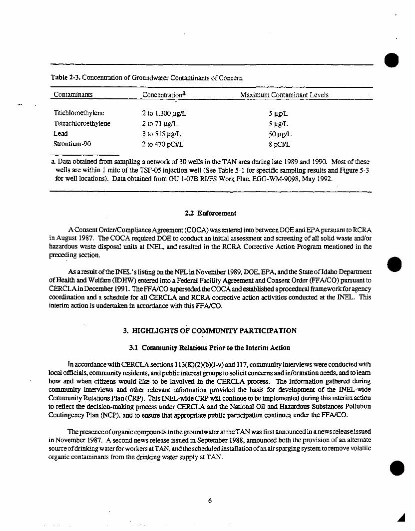
Table 2-3. Concentration of Groundwater Contaminants of Concern •Contaminants
Trichloroethylene
Tetrachloroethylene
Lead
Strontium-90
Concentrationa
2 to 1,300 Jlg/L
2 to 71lJ.g/L
3 to 515 Jlg/L
2 to 470 pCi/L
Maximum Contaminant Levels
5lJ.g/L
5lJ.g/L
50Jlg/L
8 pCi/L
a. Data obtained from sampling a network of 30 wells in the TAN area during late 1989 and 1990. Most of thesewells are within 1 mile of the TSF-05 injection well (See Table 5- I for specific sampling results and Figure 5-3for well locations). Data obtained from OU I-D7B RIlFS Work Pian, EGG-WM-9098, May 1992.
2.2 Enforcement
AConsent Order/Compliance Agreement (COCA) was entered into betweenDOE andEPApursuant to RCRAin August 1987. The COCA required DOE to conduct an initial assessment and screening of all solid waste and/orhazardous waste disposal units at INEL, and resulted in the RCRA Corrective Action Program mentioned in thepreceding section.
As a result ofthe INEL's listing on the NPL in November 1989, DOE, EPA, and the State ofIdaho DepartmentofHealth and Welfare (IDHW) entered into a Federal Facility Agreement and Consent Order (FFAlCO) pursuant toCERCLAinDecember 1991. TheFFAlCO superseded theCOCA and established aprocedural framework for agencycoordination and a schedule for all CERCLA and RCRA corrective action activities conducted at the lNEL. Thisinterim action is undertaken in accordance with this FFAlCO.
3. mGHLIGHTS OF COMMUNITY PARTICIPATION
3.1 Community Relations Prior to the Interim Action
In accordance with CERCLA sections 113(K)(2)(b)(i-v) and 117, community interviews were conducted withlocal officials, community residents, and public interest groups to solicitconcerns and information needs, and to learnhow and when citizens would like to be involved in the CERCLA process. The information gathered duringcommunity interviews and other relevant information provided the basis for development of the INEL-wideCommunity Relations Plan (CRP). This INEL-wide CRP will continue to be implemented during this interim actionto reflect the decision-making process under CERCLA and the National Oil and Hazardous Substances PollutionContingency Plan (NCP), and to ensure that appropriate public participation continues under the FFAiCO.
Thepresenceoforganic compounds in the groundwater at theTAN was first announced in a news release issuedin November 1987. A second news release issued in September 1988, announced both the provision of an alternatesourceofdrinkingwaterforworkersatTAN,andthescheduledinstallationofanairsparging system to remove volatileorganic contaminants from the drinking water supply at TAN.
6
•
•
•
•
3.2 Community Relations to Suppbrt Selection of a Remedy
In accordance with CERCLA sections 113(K)(2)(b)(i-v) and 117. the public was given the opportunity to
participate in the remedy.selection process.
The Notice of Availability for the Proposed Plan was published January 5, 1992, in the following newspapers:• The Post Register (Idaho Falls),
The Idaho State Journal (Pocatello),• Twin Falls Times News,• Idaho Statesman (Boise),• The Lewiston Morning Tribune,• Idaho Free Press (Nampa),• South Idaho Press (Burley),• Moscow-Pullman Daily News.
A similar newspaper advertisement was published January 30, 1992, inThe Post Register (Idaho Falls),
• The Idaho State Journal (Pocatello),• Twin Falls Times News,• Idaho Statesman 30ise),• Idaho Free Press (Nampa),• the South Idaho Press (Burley).
These advertisements repeated the public meeting locations and times. Personal phone calls were made toinform individuals and groups about the comment opportunity. A "Dear Citizen" letter transmitting a copy of theProposed Plan was mailed January 8, 1992 via a mailing list of 5,731 names of groups and individuals.
The public comment period was initially scheduled from January 13, 1992, to February 12,1992. Threepublicmeetings were held on February 4,5, and 6, 1992, in Idaho Falls, Boise, and Burley. Representatives from the DOE,EPA, IDHW, and EG&G Idaho, Inc., were present at the public meetings to discuss the Proposed Plan, answerquestions, and receive both written and oral pUblic comments. For one hour priorlo each meeting, INEL, EPA, andIDHW representatives were also available for informal discussions with the interested public. A court reporter waspresent at each meeting to record, verbatim, the proceedings ofthe meetings. Copies ofthe transcripts from the publicmeetings are available for public review in the Information Repositories (which are located at the public libraries inBoise, Twin Falls, Pocatello, Idaho Falls and the University ofldaho library in Moscow) as part ofthe AdministrativeRecord for this interim action.
A request for an extension of the public comment period was received and granted, therefore extending thecomment period to March 13, 1992. A notice of the extension was published February 18 and 19. 1992, in:
• The Post Register,The Idaho State Journal,Twin Falls Times News,Idaho Statesman,The Lewiston Morning Tribune,
• Idaho Free Press,South Idaho Press, and
• Moscow-Pullman Daily News.
7
•On March 9, 1992, a technical briefing was conducted with the League of Woman Voters of Moscow via aconference call.
A Responsiveness Summary has been prepared to address public comments as part ofthis Record of Decision(ROD). All verbal comments giyen at the public meetings and all submitted written comments are repeated. verbatim,in the Administrative Record for the ROD. Those comments are annotated to indicate which response in theResponsiveness Summary addresses each comment.
Inaccordance with CERCLA section 113 (K)( 1),an Administrative Record was established to provide thebasisfor selection ofthe remedial action. The Administrative Record is available for pUblic review at the INEL technicallibrary in Idaho Falls. Copies ofthe Administrative Record are available for public review at the pUblic libraries atBoise, Idaho Falls, Pocatello, and Twin Falls, and the University of Idaho Library in Moscow.
Persons on the mailing list will receive a notice ofavailability stating that the signed ROD is aVailable. Copiesof the ROD and the Responsiveness Summary will be placed in the Administrative Record and in the informationrepositories, and will be prOVided to the public upon request.
4. SCOPE AND ROLE OF THE OPERABLE UNIT
The INEL is divided into ten WAGs. The TAN has been designated as WAG 1, which is further divided intoten OUs. The TSF-oS injection well and surrounding groundwater contamination are one ofthe TAN OUs. It maybe appropriate to implement an interim action for an 0 Ubefore completing the RIIFS. Because sufficient data have •been collected regarding the TSF-OS injection well, the OU was further subdivi4ed into OU 1-D7A (interim action)and OU 1-D7B (TAl'l groundwater RIlFS).
OU 1~7A, the subject of this ROD, addresses the groundwater contaminants near the TSF-OS injection well.Thus, this interim action will help prevent further degradation of groundwater while the OU 1-D7B RIlFS is beingcompleted. During Remedial Design, the engineering phase that follows this ROD, technical drawings andspecifications will be developed for the implementation of this interim remedial action.
To the extentpracticable, this interim actionwill facilitate the OU I-07B RIIFS by prOViding information aboutaquifer parameters based on data from the groundwater extraction and monitoring wells. In addition, this interimaction will provide site-specific performance information that can be used for eValuating alternative technologies,determining process sizing, and estimating costs. Because this interim action is not the final remedy for the TSF-DSinjection well and surrounding groundwater. subsequent investigations are planned to fully address the potentialthreats posed by the conditions at the site. This interim action will not be inconsistent with nor preclUde theimplementationofthe final response action scheduled to be determined in 1994. In the event thatcontinued operationofthis limitedscope remedy is determined to be appropriate. operational parameters will be defined in the au I-07BROD.
S. SUMMARY OF SITE CHARACTERISTICS
5.1 Geology
The geology of TAN is characterized by a relatively thin layer (0 to SO ft) oflacustrine sediments and playadeposits consisting of silts. clays, and minor sands. Underlying the surficial sediments is a thick sequence of basalt •flows with sedimentary interbeds. The basalts exhibit a wide range oflithologic textures and structures~ trom denseto highly vesicular basalt and from massive to highly fractured basalt. Individual flow units consist of a fractured!
8
TSF FICiity
B B'
" :~.':..'"::~'":-
";7. :.a
4200-
<:'
~~ 400
iie· 0lI00
!··:.c "'00 -.5t
~~lU
•
1000I
lOCO ~i
SCIle(!MlI
Figure 5-1. Hydrogeological profile of the Test Area North.
Figure 5-2. Plan view ofTest Area NOM showing the location of cross-section B-B' .
•
• 9 Reproduced frombest available copy.
rubbly flow top, a midcfie dense basalt, and a fraeturedlrubbly flow bottom. These flow units have a thickness ofapproximately 15 ft. Sedimentary interbeds occur within the basalt and consistofclayor silt. Interbeds that have beenencountered to the maximum depth drilled include the P-Q and Q-R interbeds. Figure 5-1 is a cross-section throughTAN. The location of the cross-section is shown in Figure 5-2. The P-Q interbed is discontinuous. The deeperinterbed. Q-R, is interpreted to be continuous and slopes to the southeast. It has a variable thickness with a medianthickness ofapproximately 4 ft. Interpretationofhydraulic head dataindicates that thls interbed couldbe acontinuous,semi-confining layer. Both interbeds and the impact of the TAN geology on remedial alternatives will be evaluatedin more detail in the au 1-07B RIlFS.
5.2 Hydrogeology
The water table underneath the TSF facility averages about 4583 ft above mean sea level [at well United StatesGeological Survey (USGS)-Z4Jor about Z13 ft below land surface with a seasonal variation ofabout 4 ft. The watertable also has a relatively flat horizontal hydraulic gradient (1 ftlmile). In general, the depth to groundwaterimmediately beneath the land surface at TAN is approximately 200 to 220 ft. The aquifer thickness could be greaterthan 900 ft. The groundwater flow velocity in the vicinity ofTAN is generally south-southeast, and flow velocitiesrange from 0.003 ftlday to 6.0 ftlday, with a median velocity of approximately 0.3 ft/day. Transmissivity estimatesrange from 400 to 800,000 ft2/day, with a median transmissivity of approximately 38,000 ftZ/day.
The au 1-07B RIlFS is investigating whether the Q-R interbed is continuous and creates semi-confiningconditions.
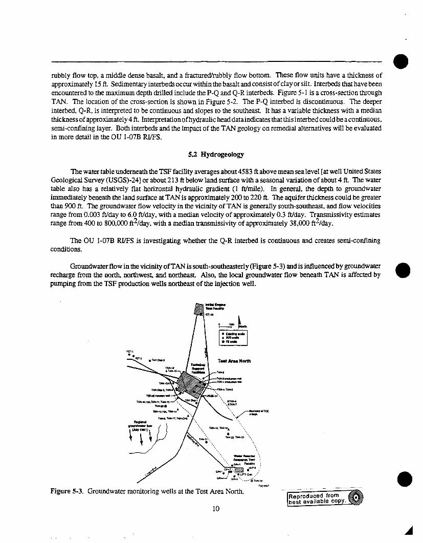
Groundwater flow in the vicinity ofTAN is south-southeasterly (Figure 5-3) and is influenced by groundwaterrecharge from the north, northwest, and northeast. Also, the local groundwater flow beneath TAN is affected bypumping from the TSF production wells northeast of the injection well.
" T~TANoI
2;',.\, .aT..,...
',~TM-7
". /e....,.efTC£••••~ :a1lOl
T~I"1'AH-1 ••
$ '-.TAH-22. TAH-2' \ ..
-_'.. "-dt T_t "•'. • GW-' Facility :
~,~l'. .~P" ,:• ,. 'WL.PTFOIO .:
G~.J Gl:'3'·....-.$;N+-2.TnO'S$1
•
•
•Figure 5-3. Groundwater monitoring wells at the Test Area North.
10
Reproduced frombest available copy.
•
•
•
5.3 Nature and Extent of Contamination
Although there may be other sources. past waste disposal in the TSF-05 injection well is considered to be theprincipal source of groundwater contamination at TAN. In general. the highest contaminant concentrations weredetected in samples from well TSF-05 (Tables 5-1 and 5-2). TCE concentrations ranging from 24.000 J.Lg/L to 35.000J.Lg/L were detected in groundwater samples collected from the TSF-05 well during 1987 through 1989. Then. inJanuary and February 1990. sludge was removed from the lower 55 linear ftofthis well. The sludge was analyzedfor total metals. total organics. radionuc1ides. and Toxicity Characteristic Leachate Procedure (TCLP) metals,organics. pesticides, and herbicides. The concentrations ofcontaminants detected are presented in Table 5-3. On thebasis of the high concentrations of organic and radiological constituents detected in the sludge. this material wasconsidered to be a major source of groundwater contamination in the TSF-05 injection well and the surroundinggroundwater. Although there are no additional data at this time, contaminant concentrations in the TSF-G5 well areexpected to have declined since the sludge was removed. Groundwater sampling associated with the interim actionand the au I-G7B RIlFS will determine current contaminant concentrations in the TSF-05 injection well and otherwells at TAN. Also. potential sources ofgroundwater contamination at TAN otherthan the TSF-05 injection well willbe evaluated under the au 1-07B RIlFS.
Preliminary interpretations regarding the extent of contamination at TAN are summarized below. Theseinterpretations are basedon theprevious sampling results presentedin Tables 5-1 and5-2, and will be further evaluated(with new sampling data) as part of the au 1-07B RIlFS. A groundwater contaminant plume extends generallysoutheastward from the TSF-05 injection well. which is consistent with the main direction of groundwater flowbeneath TAN. Some contaminants have also been detected northeast of well TSF-G5; contaminant migration in thisdirection is probably caused by localized shifts in groundwater flow directions resulting from pumping the TANproduction wells (TAN-l and TAN-2). As stated previoUSly, the contaminants of concern for the interim actionincludeTCE, PCE, lead, and strontium-90. These foUr contaminants have been detected at varying distances from theTSF-G5 injection well, apparently reflecting differing rates of migration through the groundwater. TCE is the mostwidespread constituent in the contaminantplume, having been found above MCLs as far as 1.5 miles southeast of theTSF-G5 well. PCE has been detected in wells as far as 1 mile southeast of the TSF-05 well. Concentrations ofstrontium-90 and lead above their respective MCLs have only been regularly detected within 1/2 mile of the TSF-05well.
The vertical extent ofgroundwater contamination at TAN is not yet clearly defined. Most wells at TAN arescreened or open across the water table (which occurs at depths of approximately 200 ft or 4590 ft above mean sealevel). The contaminant plume was detected primarily from groundwater samples collected from these wells. Thedeepest detected contamination was found in a sample from well TAN-12, which is screened at a depth of362 to 382ft; approximately 165 ft below the water table at an elevation of 4420 ft above mean sea level. However, there arerelatively few wells at TAN which are screened only across deep intervals. Therefore, the vertical extent ofcontamination is largely unknown. There is no information, for example. to indicate whether contaminants havemigrated below the Q-R interbed (Figure 5 -1), which is interpreted to be a semi-confining bed beneath TAN. Newwells will be installedas apartoftheOU I-07B RIlFS to help betterdefinethe verticalextentofthecontami·nantplume.
On the basis ofthe previous sampling data presentedin Table 5-1 and discussed above, the contaminantplumebeneath TAN is estimated to be approximately 1.5 miles in length. 0.5 miles in width. and 200 ft thick. Although thereare numerous uncertainties associated with this estimate (particularly regarding the plume thickness). it is asufficientinitial characterization for interim action design purposes. As stated above. subsequent groundwater sampling for theinterim action and the au 1-07B RIlFS will further refine this initial characterization.
11
•Table 5-1. Groundwater monitoring well data.
WellmUne ANP-06a ANP-08 ANP.Q9a FET-02 IET-06 TAN-OIScreened interval. 230-250 232-304 240-260 215-230 220-240 200-350ft below land surfaceDistance from TSF-05. ft 10.630 I 8420 16.210 4340 6460 2320When sampledD NIYIY NIYIY NIY!Y NIYIY YIY!Y NIYIYContaminant, l!gJL IAcetone IBenzene 18/NDIND
2-Butanone
Carbon Disulfide 2/NDIND
Carbon Tetrachloride
Chloroform
Chloromethane
Dibromochloromethane
1.1 Dichloroethane
1.1 Dichloroethylene
1.2 Dicb1oroetbane NAl51ND
1.2 Dich1oroetby1ene (total)
Methylene Chloride
Tetrachloroethylene NAfJ./3 NA12J3
Toluene
1,1,1 Trichloroethane
Trichloroethylene NAl6n NAnI8
Vinyl Chloride
Barium
Chromium NAIl 1117
Lead NAlNDn NAlNDI15 8/ND/lO
Mercury
Gamma. pCi/L NAINDIND
Strontium-90, pCiIL NAIND/2 NAINDIND NA/412
Tritium, pCiIL NAINDIND NAlNDI240.
•
Note: FIrst value given is from March 1989 groundwater monitoring well sampling. Second is from November 1989.and the third is from November 1990. ND is non-detect. NA means a sample wasn't taken from that well in thatsampling event If no data are given, the contaminant has not been detected in that well during the listed samplingevents.
a. Wells ANP-06 and ANP-09 are not shown on Figure 5-3. ANP-06 is 10.630 feet northwest ofTSF-05. AJW-09is 16,210 ft sout.~eastof TSF-05.
b. Indicates when each well was sampled (Le. Y/Y/Y means the well was sampled in March 1989, November 1989. •and November 1990).
12
•
•
•
Table 5-1. (continued).
Well name TAN-02 TAN-03 TAN-04 TAN-OS TAN-06 TAN-07Screened interval, 235-335 230-235 235-240 280-285 235-255 29S-318ft below land surfaceDistance from TSF-05. ft 1930 2340 1410 1380 4990 5000When sampledb NIYIY NIYIY NIYIY NIYIY NINIY NINIYContaminant, ""gIL
Note: First value givenis from March 1989 groundwater monitoring well sampling. Secondis from November 1989,and the third is from November 1990. ND is non-detect. NA means a sample wasn't taken from that well in thatsampling event. If no data are given, the contaminant has not been detected in that well during the listed samplingevents.
b. Indicates when each well was sampled (Le. YNN means the well was sampled in March 1989, November 1989.and November 1990).
13
Table 5-1. (continued).
Well name TAN-08 TAN-Q9 TAN-lO TAN-lOA TAN-ll TAN-12Screened interval. 232-304 290-295 220-225 215-250 260-265 362-382ft below land surfaceDistance from TSF-05. ft 2180 90 210 180 250 290When sampledb NfYfY NfYfY NfY/N NfYfY NfYfY NfYfYContaminant. J,1gIL IAcetone NA/6IIND
Note: First value given is from March 1989 groundwater monitoring well sampling. Second is from November 1989,and the third is from November 1990. ND is non-detect. NA means a sample wasn't taken from that well in thatsampling event. If no data are given, the contaminant has not been detected in that well during the listed samplingevents.
b. Indicates when each well was sampled (Le. YrYrY means the well was sampled in March 1989, November 1989,and November 1990).
14
•
•
•
•
•
•
Table 5-1. (continued).
Well name TA.'Il-13A TA,'I/-14 TAN-15 TA,"I-16 TAN-17 TAN·DI TAN·D2Screened interval, 216-236 376-396 232-252 302·322 320-340 230-235 230-235ft below land surfaceInistance from TSF-05 ft 1370 1420 5720 5750 2200 IQ40 115When samDledb SINfY NfNfY NINfY SINfY N!NfY YfYfY YfYfY
Note: First value given is from March 1989 groundwater monitoring well sampling. Second is from November 1989,and the third is from November 1990. NO is non-detect. NA means a sample wasn't taken from that well in thatsampling event. If no data are given, the contaminant has not been detected in that well during the listed samplingevents.
b. Indicates when each well was sampled (i.e.. Y/Y/Y means the well was sampled in March 1989, November 1989,and November 1990).
15
Table 5-1. (continued).
Well name TAN-D3 USGS-24 USGS-26 GIN-2 GIN-4 TSF-05a
Screened interval. 230-235 240-245 205-2601
230-240 -
it helow land surfaceDistance from TSF-05 ft 3160 1410 14970 7700 7680When sarnpledb NIYIY YIYIY NfYIY NINIY NINIY YfNlNContaminant. j.lglL IAcetone 18INDfND
Note: First value given is from March 1989 groundwater monitoring well sampling. Second is from November 1989,and the third is from November 1990. ND is non-detect. NA means a sample wasn't taken from that well in thatsampling event. If no data are given, the contaminant has not been detected in that well during the listed samplingevents.
. a. The data given for the TSF-05 well represent groundwater conditions near the well in March 1989 before thesludge was removed from the bottom of the well in January and February 1990.
b. Indicates when each well was sampled (Le. YfYlY means the well was sampled in March 1989, November 1989,and November 1990).
16
•
•
•
• Table 5-2. Maximum detected concentrations of contaminants detected by the USGS in groundwater samplesat TAN 1987-1989.
These data represent conditions before sludge was removed from the well (refer to Section 2.1.2).
5.4 TAN Disposal Pond Data
The TAN disposal pond is an unlined, diked area built in 1972 that encompasses approximately 35 acres.Access to the entire 35 acre pond is restricted by a fence. Approximately 4 acres in the nortl!east and eastern edgesof the large disposal pond are currently in use. The remaining 31 acres are inactive (dry) and have apparently neverbeen used for any disposal operations. Review of historical records and aerial photographs, interviews with formeremployees, and a site inspection provided no evidence offormer discharges or other waste disposal operations in this31 acres of the pond. Therefore, this part of the disposal pond is considered to be uncontaminated.
The active area ofthe pond consists of two lagoons-a main lagoon and an overflow lagoon-which receiveapproximately 40,000 to 70,000 gallons per day (gpd) ofprocess waste water and treated sewage effluent. The mainlagoon and the overflowlagoon are located along the easternand northeastern edges ofthe disposal pond, respectively.Bothofthe lagoons are bermed to containthedischarge effluent within these portions ofthe large disposal pond. Somesoil contamination, resulting from past activities at TAN, has been detected in the lagoons and immediate vicinity.Detectedcontaminants include organic compounds, radionuclides, andheavy metals. Contaminantconcentrations arehighest in the upper soil layers and typically decrease with depth. Ingeneral, the highest concentrations and frequencyofdetectionwere found in the main discharge lagoon. A perched water zone exists in the vicinity ofthe activelagoonsand was routinely monitored by sampling two monitoring wells located along the northeastern and eastern edges ofthe 35 acre disposal pond. No contaminants have been routinely detected above MCLs in samples from these wells.
In summary, on the basis of the above information, most of the 35 acre disposal pond is considered to beuncontaminated. Some soil contamination is associated with the active lagoons along the northeastern and easternedges of the disposal pond. However, this contamination is localized in the upper soil layers in and adjacent to theactive lagoons and does not appear to be migrating to other portions of the large disposal pond. The nature and extentof existing contamination in the TAN disposal pond will be further evaluated under au 1-06 of the FFAICO.
17
Table 5-3. Maximum contaminant concentration in TSF-05 injection well sludge.a •...
a Data were taken from the OU 1-07B TAN groundwater RIIFS workplan. Appendix B and Appendix G.
b. TCLP extraction results for leachable VOCs.
c. Total VOCs.
d. The percentage of gross beta which is strontium-90 has not been determined.
e. These samples were obtained from water decanted or liquid extracted from the sludge.
18
•
•
•
•
6. SUMMARY OF SITE RISKS
6.1 Human Health
Although this interim action does not use a completed baseline risk assessment, sufficient information isavailable to demonstrate the potential for risk and the need to take action.
Chemical-specific standards that define acceptable risk levels such as MCLs, may be used to determinewhether an exposure is associated with an unacceptable risk to human health or the environment and whether remedialaction is warranted. Four contaminants have been found to exceed their chemical-specific MCLs in more than onewell andon arecurring basis in the vicinity ofthe TSF-QS injectionwell andtherefore are consideredto be contaminantsofconcern. Table 6-1 identifies the contaminants ofconcern, their respective MCLs, and risk-based concentrations.
Both trichloroethylene and tetrachloroethylene have been shown to cause cancer in laboratory animals suchas rats and mice when the animals are exposed at high levels over their lifetimes. Chemicals that cause cancer inlaboratory animals also may increase the risk of cancer in humans who are exposed at lower levels over long periodsof time.
Leadcan cause avariety ofadverse healtheffects inhumans. At relativelylow levels ofexposure, these effectsmay include interference with red blood cell chemistry, delays in normal physical and mental development in babiesand young children, slight deficits in the attentiOn span, hearing, learning abilities ofchildren, and slight increases inthe blood pressure of some adults.
Strontium-90 is a fission product and a beta particle emitter. Strontium-90 accumulates in bone tissue and iftaken internally, can damage the bone marrow and bone tissue which can cause cancer. Children are more susceptibleto impacts from the strontium-90 because their bones are developing more rapidly than in an adult. Beta particles canpenetrate the skin, so these particles can also damage the skin and eyes.
The potentiallyexposedpopulations includesite workers and site visitors. Thereasonableexposure pathwaysfor each group are ingestion of contaminated groundwater and inhalation of volatiles. The immediate threat ofexposure has been mitigated by the installation of an air sparger system in the drinking water supply. Although theair sparger reduces the risk ofexposure, itdoes not address the source ofgroundwater contamination or the protectionof future drinking water supplies. For a future residential scenario where people might live on part of the INEL, adrinking water well could draw contamination from a portion of the contaminant plume.
Actual or threatened releases of hazardous substances from this site, if not addressed by implementing thisinterim action selected in this ROD, may present an imminent and substantial endangerment to public health, welfare.or the environment.
A quantitative human health risk assessment will be included as part of au I-07B RIfFS.
6.2 Ecological Risk Assessment
Anecological risk assessment was not performed for this interim action. Aquantitative ecological assessmentwill be performed as part of the lNEL-wide comprehensive RIfFS scheduled for 1998.
19
•Table 6-1. Contaminants of concern, their respective MCLs, and risk-based concentrations.a
Trichloroethylene 5 2.0E-6 3 300 NATetrachloroethylene 5 2.0E-6 1 100 400Lead 50 NA NA NA NARadiQDUClides MCL
(pCi/L) (pCiIL) (pCiIL) (pCiIL)
Strontium-90 8 1.0E-5 0.60 60 NA
a. The data that support this list of contaminants are contained in Table 5-1. The contaminants were taken from validateddata from 1989 and 1990 groundwater sampling and include only those contaminants that were found in both years.Contaminants that were not found above MCLs in more than one well and on a recurring basis were not included in thislist
7. DESCRIPTION OF ALTERNATIVES
Four alternatives were considered for this interim action: (1) no action; (2) groundwater extraction andtreatment by air stripping, carbon adsorption, and ion exchange; (3) groundwater extraction and treatment by carbonadsorptionand ionexchange; and (4) groundwaterextraction and treaonent by chemical destruction and ion exchange. •These four alternatives are discussed in greater deWI below.
7.1 Common Features
Each of the alternatives, except for the no action alternative, have the following common features:
• .Existing institutional controls such as the air sparger and monthly drinking watermonitoring program willcontinue. New administrative and institutional controls will be implemented as appropriate to supplementengineering controls and minimize exposure to releases of hazardous substances during remediation.
•
•
•
•
•
Will operate for a maximum of two years.
Will pump at an average rate of approximately 50 gallons per minute (gpm) and occasional rates of 10to lOOgpm.
Will achieve performance standards (given in Table 9-2) for contaminants of concern in the treatedgroundwater effluent.
Groundwatermonitoring wells withinthecontaminantplume will monitor the effectiveness ofthe interimaction in reducing contaminant concentrations in the groundwater. These wells may also be used asextraction wells to expedite the removal ofcontaminated groundwater.
Include installingon-site groundwater treatment facilities to remove contaminants from the groundwater.The treated effluent will be discharged to the TAN disposal pond.
20
•
•7.2.1 Alternative 1: No Action
7.2 Alternatives
•
•
The NCP reqUires tharthe "no-action" alternative be considered for every site to determine a baseline againstwhich other remedial alternatives can be measured. Under this alternative, no remedial actions would be taken beyondthose already in place such as the air sparging system. The monthly drinking water program would continue andgroundwater monitoring would be implemented to evaluate changes in the contaminant plume.
7.2.2 Alternative 2: Groundwater Extraction and Treatment by Air Stripping, Carbon Adsorption, IonExchange
TIlis alternative differs from the no action alternative because active measures would be taken to reduce thecontaminants near the TSF-05 injection well and in the surrounding groundwater, which would reduce the threat todrinking water supplies and help prevent further degradation of groundwater while the au l-07B RIlFS is beingcompleted. Alternative 2 employs well-established and widely used technologies..
Groundwater will be extracted from the TSF-05 injection well and perhaps nearby groundwater monitoringwells that are capable of capturing contaminated groundwater. The extracted groundwater would be pumped to anon-site facility comprised of: a filtration system to remove sediment, an air stripper equipped with a carbon scrubberto remove organic contaminants; and an ion exchange system to remove inorganics and radionuclides. The filtrationsystem is a physical process that removes suspended solids from the groundwater. This system could be a tank wheresolids are allowed to settle out of the groundwater or a porous media such as sand or paper that captures the solidparticles as the groundwater passes through. the filter. Sediment would be analyzed for hazardous and radioactivecontaminants and will be disposed of as identified in Table 9-1.
Air stripping is a mass'Transfer process in which volatile contaminants in water are transferred to gas. Airstripping is frequently accomplishedin apacked towerequipped with an air blower. In this type ofsystem, water flowsdown through a packing material that produces a large surface area for gas transfer, while air flows upward. and isexhausted tprough the top. Becadse volatile contaminants such asTCE andPCEhave arelatively high vapor pressure,they readily leave the aqueous stream for the gas phase. Air flowing through the top of the air stripper would passthroughanactivatedcarbon treatmentsystem to capture the organic contaminants releasedfrom the grOundwater. Theactivated carbon would selectively adsorb the contaminants by asurface attraction phenomenon in which the organicmolecules are attracted to unsatW.ied electrostatic charges on and in the pores of the carbon granules. Air from theair stripper may also be passed th,r.ough a filter to remove solid particles, radioactive particles, and water mists thatmightbe generated from the air stripper. Air emissions would be monitored for compliance with regulatory standardsfor air pollutants. The carbon treatment system would be monitored for contaminant breakthrough, and as necessary,the carbon would be replaced. Thespentcarbon would beregeneratedat a facility operating incompliance with EPA'sRevised Procedures for Planning and Implementing Off-Site Response Actions.
In addition to passing through the air stripper, the groundwater would also pass through one or more ionexchange columns. Ion exchange is a process Whereby the dissolved metals and radionuclides are removed from thegroundwater by being exchanged with relatively harmless ions heldby the ion exchange material. Ionexchange resinsare primarily synthetic organic materials containing ionic functional groups to which exchangeable ions are attached.Although specific ion exchange and sorptive resins systems must be designed on a site-specific basis. typicalconfigurations include parallel columns to allow for one or more columns to be taken out for regeneration while theremaining columns would stay in service. Procedures for recovery or regeneration of the spent resins would bedetermined during remedial design. It is anticipated that the spent resins would be disposed of in available storageareas at the Radioactive Waste Management Complex (RWMC) at the INEL as low-level radioactive waste.
21
•The treated effluent would be monitored for treatment efficiencyprior to discharge to the TAJ."1 disposal pond,where the effluent would evaporate and percolate into the ground.
7.2.3 Alternative 3: Groundwater Extraction and Treatment by Carbon Adsorption and Ion Exchange
Although the purpose ofthis alternative is the same as Alternative 2, adifferent groundwater treatment systemis proposed which uses activated carbon as the primary treatment technology for the removal oforganic contaminants.The remedial objective, filtration, ion exchange, and effluent disposal systems remain the same, but an activatedcarbon system would replace the air stripper and associatedoffgas treatment system. Activated carbonis a technologythat is adaptable for the removal of organic and inorganic contaminants from both air and aqueous wastes.Alternative 3 employs well-established and widely used technologies.
Following pretreatment by the filtration system. the contaminated groundwater would be passed throughseveral carbon adsorption columns where the carbon would selectively adsorb the organic contaminants. In addition,the water would also pass through ion exchange columns to remove inorganic contaminants and radionuclides. Useofseveral carbon adsorption columns would provide considerable t1exibility. Various columns could be arranged inseries to increase service life between regeneration or in parallel for maximum hydraulic capacity. The pipingarrangement would also allow for one or more beds to be regenerated while the other columns remain in service.
The disposal ofthe sediment and spent resins would be the same as for Alternative 2. Spent organic carbonunder this alternative couid contain organic and inorganic contaminants as well as radionuclides. In this instance, thespent carbon could be classified as a combustible mixed waste that would require disposal on-site at the Waste •Experimental Reduction Facility (WERF) or similar facility.
7.2.4 Alternative 4: Groundwater Extraction and Treatment by Chemical Destruction and Ion Exchange
Although the purpose ofthis alternative is the same as Alternatives 2 and 3, adifferent groundwater treannentsystem is proposed. The remedial objective, fIltration, ion exchange, and effluent disposal systems remain the same,but a chemical treatment system would replace the air stripping or activated carbon systems.
Following pretreatment by the fIltration system, the contaminated groundwater would be passed through achemical treannent system to destroy the organic contaminants, and an ion exchange column to remove inorganiccontaminants and radionuclides. The chemical treatment system would detoxify organic contaminants by actuallychanging theirchemical forms from complex organic molecules to simple, more benignmolecules by using ultravioletlight and either ozone or hydrogen peroxide. The ultraviolet light provides an energy source to break chemical bondswhile the ozone or hydrogen peroxide provides an oxygen atom to fonn benign compounds.
The disposal of sediments and spent resins would be the same as Alternative 2. Treatment residualscontaminated with organic compounds would not be generated and would not need to be disposed
8. SUMMARY OF COMPARATIVE ANALYSIS OF ALTERt"lATIVES
The remedial alternatives for the TSF-05 injection well and surrounding groundwater interim action werecompared according to nine criteria developed on the basis of the statutory requirements ofCERCLA Section 121 andthe NCP. These evaluation criteria are shown below and discussed in the follOWing sections.
• Threshold criteriaOverall protection of human health and the environmentCompliance with applicable or appropriate and relevant requirements (ARARs)
22
•
•
•
•
• Primary balancing criteria
Long-tenn effectiveness and pennanenceReduction of toxicity, mobility, or volume through treatmentShort-tenn effectivenessImpiementabilityCost
• Modifying criteria
State acceptanceCommunity acceptance.
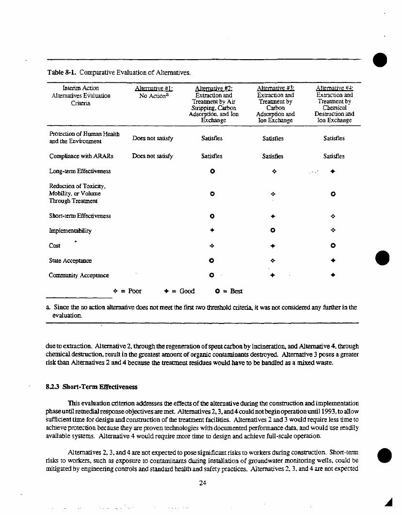
A summary of the comparative analysis of alternatives is shown in Table 8-1.
8.1 Threshold Criteria
8.1.1 Overall Protection of Human Health and the Environment
This criterion measures how the alternative, as a whole. achieves and maintains protection of human healthand the environment within the scope of this action. Alternative I is not protective of human health and theenvironment. It neither reduces the threat ofexposure to drinking water supplies nor prevents further degradation ofthe groundwater. Alternatives 2. 3. and 4 areprotective ofhuman health andthe environment Each alternative reducesthe risk to potentially exposed populations and prevents further degradation of the groundwater.
8.1.2 Compliance with Applicable or Relevant and Appropriate Requirements
This evaluation criterion is used to determine whether each alternative will meet all of the Federal and StateARARs that have been identified for this interim action. Compliance with an ARAR as an evaluation criteria is notapplied to Alternative 1. the baseline alternative. Alternatives 2. 3. and 4 achieve compliance with the ARARs. Thisanalysis is summarized in the Statutory Determinations section.
8.2 Primary Balancing Criteria
8.2.1 Long-Tenn Effectiveness and Pennanence
Theevaluationofalternativesunder this criterion. the results ofaremedial action interIDSoftheriskremainingat the site after response objectives have been met and the extent and effectiveness ofthe controls that may be requiredto manage treatment residuals are addressed. Because the spent carbon produced by Alternative 2 would beregenerated off-site. Alternative 2 would provide a higher degree of long-term effectiveness and permanence thanAlternatives 3 or 4. Alternative 3 is less reliable because of the necessity of long-tenn management controls forproviding continued protection from potential mixed-waste residuals. Alternative 4 is less reliable because of theuncertainties associated with long-term operation and maintenance functions.
8.2.2 Reduction of Toxicity, Mobility, or Volume through Treatment
Thisevaluation criteriaaddresses the statutory preference for selecting remedial actions that employ treatmenttechnologies that permanently and significantly reduce toxicity. mobility. or volume of the hazardous substances astheir principal element. Alternatives 2.3, and 4 reduce the mobility and volume of contaminants in the groundwater
23
a. Since the no action alternative does not meet the first two threshold criteria, it was not considered any further in theevaluation.
due to extraction. Alternative 2, through the regeneration ofspentcarbon by incineration, and Alternative 4, throughchemical destruction, result in the greatest amount oforganic contaminants destroyed. Alternative 3 poses a greaterrisk than Alternatives 2 and 4 because the treannent residues would have to be handled as a mixed waste.
8.2.3 Short-Term Effectiveness
This evaluation criterion addresses the effects of the alternative during the construction and implementationphaseuntil remedial responseobjectivesare met. Alternatives 2, 3, and4 could not beginoperationuntil 1993, to allowsufficient time for design and construction of the treatment facilities. Alternatives 2 and 3 would require less time toachieve protection because they are proven technologies with documented performance data, and would use readilyavailable systems. Alternative 4 would require more time to design and achieve full-scale operation.
AIternatives 2, 3, and 4 are not expected to pose significant risks to workers during construction. Short-tenn •risks to workers, such as exposure to contaminants during installation of groundwater monitoring wells. could bemitigated by engineering controls and standard health and safety practices. Alternatives 2. 3. and 4 are not expected
24-
•
•
•
to pose significant risks of exposure to workers during the handling and transportation of wastes. Short-term riskscould be mitigated by engineering controls and standard health and safety practices. Alternative 2 is not expected topose a significant risk of exposure to the community during transportation of spent carbon to a recycling facility orduring regeneration of the carbon by incineration. Organic contaminants would be bound to the car.bon duringtransport and not subject to rapid release in the event of an accident Incineration would occur at an EPA-approved· .facility designed to safely handle the contammated carbon. Short-term risks could similarly be mitigated byengineering controls and standard health and safety practices. Alternative 4 has the disadvantage of requiring moreextensive bench- or pilot-scale studies than the other alternatives before a larger scale treatment system could bedesigned. In addition, this alternative would require more complex technology, which would increase the risk to meworkers and the environment if a failure occurred.
8.2.4 Implementability
The implementability criterion addresses the technical and administrative feasibility of implementing analternative as well as various services and materials required during its implementation. Alternatives 2 and 3employwell-established technologies that are widely used in the treatment ofhazardous waste streams. Air stripping, carbonadsorption, and ion exchange are easily integrated into complex treatment systems. Alternative 4 includes chemicaloxidation to destroy organic contaminants. Treatability studies are necessary to demonstrate the applicability andperformance ofthis technology for a specific site; and therefore, the technical uncertainties associated with design andconstruction may hinder implementation. The necessary equipment and specialists as well as services and materialsare expected to be readily available for each alternative. From the perspective of waste treatment and disposal.Alternative 3would be more difficult to implement than Alternative 2 which would be more difficult than Alternative4. Alternative 3 would be difficult to implement because it is possible that a mixed waste would be generated andtreatment and disposal options for mixed waste are very limited. Alternative 2 would be more difficult to implementthan Alternative 4 because spent carbon would need to be transported off-site for regeneration. Alternative 4 wouldbe the most implementable from a waste treatment and disposal perspective because no mixed or hazardous wastewould be generated.
8.2.5 Cost
The evaluation ofalternatives under this criteria includes capital costs and annual operation and maintenancecosts. Alternative 3, estimated at $7,440.000. is the least expensive of the treatment alternatives. Alternative 4 isestimated at $7,360,000. followed by Alternative 2 at $7.715.000. A summary breakdown of these costs for eachalternative is shown in Table 8-2.
8.3 Modifying Criteria
8.3.1 State Acceptance
This assessment criterion evaluates the technical and administrative issues and concerns the IDHW may haveregarding each of the alternatives. The IDHW concurs with the preferred remedial alternative. The IDHW has beeninvolved with the development and review of the ProposedPlan, Record ofDecision, and other project activities suchas public meetings.
8.3.2 Community Acceptance
This assessment evaluates the issues and concerns the public may have regarding each of the proposedalternatives. On the basis ofverbal comments received during the public meeting held February 4.5. and 6. 1992 andwritten comments received during the comment period ending March 13. 1992, the community appears to accept the
25
1. Design includes costs ($25,000 for Alternatives 2 and 3, and $50,000 for Alternative 4) for the small-scale designstudies needed to improve actual performance of the treatment plant.
2. Well drilling could include conversion of five existing wells to monitoring wells, drilling of two new monitoringwells near the TSF-05 injection well, and waste treatment and disposal. These wells would be in addition to thewells drilled under the RIIFS.
3. Contingency (25%) covers uncertainties in construction and operating costs only.
26
•
•
•
preferred remedial alternative. Specific responses and comments to the remedial alternatives may be found in theattached Responsiveness Summary (Appendices A and B).
9. SELECTED REMEDY
On the basis ofconsideration ofthe requirements ofCERCLA. the detailed analysis of the alternatives usingthe nine criteria, and public comments. DOE. EPA, and IDHW have determined that Alternative 2 (GroundwaterExtraction and Treatment by Air Stripping. Carbon Adsorption. and Ion Exchange) is the most appropriate remedyfor OU I-07A.
The objectives of the interim action are twofold:
• Reduce the contaminants near the TSF-05 injection well and in the surrounding groundwater.
• Measure aquifer parameters based on data from the groundwater extraction and monitoring wells.
Removing contaminants will help prevent further degradation ofgroundwater while the OU I-07B RIIFS isbeing completed. Performance information will facilitate the au I-07B RIIFS by providing site-specific data to beused to evaluate the potential performance and engineering requirements of final remedial actions.
On the basis of existing information and 3.l! analysis of all remedial alternatives. DOE. EPA. and IDHWbelieve that the selected remedy will achieve these objectives. The interim action will end if it is determined that itis no longer effective or when the ROD for au 1-07B is signed. The au 1-07B ROD will address future use of thecomponents of the interim action remedy.
9.1 Major Components of the Selected Remedy
The major components of the selected remedy include:
•
•
•
•
•
Extract contaminated groundwater from the TSF-05 injection well and perhaps nearby groundwatermonitoring wells that are capable of capturing contaminated groundwater.
Install two groundwater monitoring wells within the contaminant plume t6 motlitor the effectiveness ofthe interim action. These wells may also be used as extraction wells to expedite the removal ofcontaminated groundwater.
Install on-site groundwater treatment fadlities to reduce contaminants of concern in the extractedgroundwater to prescribed performance standards. The selected treatment system is air stripping. carbonadsorption, and ion exchange.
Motlitor the groundwater contaminant plume and the extraction/treatment system during groundwaterextraction activities to track the effectiveness ofthe system and to ensure that performance standards areachieved.
Modifytheexisting TAN disposal pond to receive the treatedgroundwater and ensure thatdischarge waterquality does not further degrade the underlying Snake River Plain Aquifer above maximum contaminantlevels.
Implement administrative and institutional controls that supplement engineering contro~s and minimizeexposure to releases of hazardous substances during remediation.
27
During operation of the interim action, the system's perfonnance will be monitored on a regular basis andmodified as warranted by the performance data. Modification may include any or all of the following:
Alternate pumping of wells to eliminate stagnation points.
• Pulse pumping to allow aquifer equilibration and to allow adsorbed contaminants to dissolve into thegroundwater.
Discontinue pumping at individual wells where remediation objectives have been attained.
It may also become apparentduring design. implementation, oroperationofthe effluentdischarge system thatthe TAN disposal pond is not an appropriate discharge point. In such a case, the interim action will cease operationuntil other alternatives for effluent discharge can be considered.
Theresidual spentcarbonwill betransported off-site for regeneration at afacilityoperatingin compliance withEPA's Revised Procedures for Planning and Implementing Off-Site Response Actions. Other waste residuals fromthe treatment process will be addressed on-site at existing facilities as described in Section 9.2.5 and Table 9-1.
9.2 Remedial Action Objectives
Theau I-Q7B RJlFS report will evaluate theeffectiveness ofthe interimacti0I!in meeting the objectives. 111isevaluation will be incorporated into the ROD for the au 1-07B RJJFS.
9.2.1 Pumping Rates
An average pumping rate of approximately 50 gpm is expected with occasional pumping rates of 10 to 100gpm.. Actual pumping rates will be determined to ensure efficient contaminant removal based on engineering andhydrogeologic considerations.
9.2.2 Treated Emuent
Alternative 2 will achieve the interim performance standards listed in Table 9-2 for the contaminants ofconcern in the treated effluent These standards are protective to levels appropriate to the use ofthe Snake River PlainAquifer as a drinking water source, and are technically practicable from an engineering perspective.
Theefiluent dischargestandards forTCE. PeE. and leadare basedonnotcreating acondition that would causeMCLs to be exceeded in the aquifer as a result of treated water discharge to the disposal pond. These standards arerelevant and appropriate as in.sinl groundwater performance standards.
The standards for protection against radiation'(10 Code ofFederal Regulations [CFR] 20) specify limits forradionuclides in effluents that may be released to unrestricted areas. Environmental fate and transport modellingdemonstrates that effluent concentrations of strontium-90 will not exceed the MCL when that effluent reaches theaquifer. The modelling considered 2 years of effluent discharge (the anticipated duration of the interim action),contaminant transport through the unsaturated zones, and radionuclide half-lives.
9.2.3 Air Emissions
Interim performance standards listed in Table 9-2 are technically practicable from an engineering perspectiveand are protective to levels appropriate for controlling emissions into the air.
28
•
•
•
• 29
•Table 9-1. (continued).
Waste Media Generated from Potential Hazardousor RadioactiveComaminailtsb
Treatment Storagea
Treatment residuals
Spent activated carbon Solid Process Equipment TCE Incinel':ltion andrecycling
at TAN storagefacility
Off-site facility
Sediments Solid Process Equipment cesium-137, cobalt-60 Incineration or grouting at TA..'l storage - ..' -RWMCfacility
Spent ion exchangeresin
Solid Process Equipment Sr-90, cesium-137,cobalt-QO
:-Jone at TAN storagefacility
RWMC
a. Treatment, storage, and disposal options given are the preferred choice. If these facilities or options are not available,equivalent facilities oroptions will be used, or the wastes will be stored at the TAN storage facility until treatment ordisposaloptions are available, or until a fmal remedy under an applicable ROD is implemented. This storage area will meet RCRAsubstantive requirements.
b. The contaminants listed are those that could potentially be found in the waste at levels above RCRA characteristic limits forhazardous contaminants or above detection limits for radioactive contaminants. These contaminants may not be found in thewastes. If these contaminants are not found, the identified treatment, storage, or disposal option would not be implemented.
c. These laboratory analysis methods use chemicals to improve the efficiency of the analysis process (i.e. methylene chloride isadded for semi-volatile analyses; and acids for metals, alphalbeta. and inorganics). If radioactive contamination is detected •in the analysis waste. these chemicals would be returned to the INEL. These laboratory wastes may be generated to determineappropriate disposal of the process and investigation-derived wastes. These laboratory wastes would be small in volume (lessthan l00mL persample), thus the waste would bestoredsimilar to Note (a) until sufficient volume isavailable for the identifiedtreatment option.
d. These cuttings would be surveyed with field instruments for hazardous and radiological contamination. If the cuttiilgs do notexceed screening action levels (less than 25 parts per million organics based on headspace analysis, less than 100 counts perminute ofbeta!gamma. orno detectable alpha), they will be disposed ofnext to the TAN disposal pond. Ifthe cuttingsexceedaction levels, they will be stored at the TAN storage facility or a radioactive storage area. pending ultimate disposal based ontheir waste characteristics.
e. Semi-volatiles are not contaminants of concern, but laboratory analyses could be used for screening purposes.
The emissionstandardfor leadwill notexceed 1.5 micrograms percubic meter, as prescribedby40CFR 50.12(National primary and secondary ambient air qUality standards for lead). The emission standard for strontium-90 willnot exceed an effective dose equivalent of 10 millirem per year (mremlyr), as prescribed by 40 CFR 61.92 (Nationalemission standards for emissions of radionuclides other than radon from Department of Energy facilities).
Emission standards for trichloroethylene and tetrachloroethylene were derived using the Idaho Air QualityBureau's New Source Policy for Toxic Air Pollutants in accordance with Idaho Administration Procedures Act(lDAPA) §16.01.01952,02. Although not legally enforceable, these guidelines will be addressed in implementing theinterim action.
9.2.4 Obtain Data on Aquifer Performance
To the extent practicable, data collected under the remedial alternative on contaminant removal effectivenessfrom the aquifer (sustained contaminant levels), on aquifer characteristics (transmissivity and well response), and on
b. Emission standards for trichloroethylene and tetrachloroethylene were derived using the Idaho Air Quality Bureau's New Source Policy forToxic Air Pollutants in accordance with IDAPA 16.01.01952.02.
c. Ambient air concentrations for the lead were taken from 40 CFR Part 50.12. Primary and Secondary Ambient Air Standards for Lead.
d. Emission standards for strontium-90 are aNational Emission Standard for Hazardous Air Pollutants standard for the effective dose equivalentto the public under 40 CFR Part 61.92, National Emission Standards for Emissions ofRadionuclides Other Than Radon from DepartmentofEnergy Facilities.
contaminant levels in the groundwater (types and concentrations of contaminants) will also be used in the OU 1-07BRIlFS. These data will be used in the evaluation of the alternatives considered for the final action under the OU 107B RIfFS.
9.2.5 RCRA Waste Characteristic Determination
On the basis of an evaluation of existing documentation. DOE has determined that the groundwatercontaminants are not listed RCRA hazardous wastes. As appropriate, investigation-derived wastes and treatmentresiduals will be sampled and analyzed in accordance with §IDAPA 16.01.05005. If these wastes exhibit RCRAcharacteristics, the wastes wouldbe handledin accordance withRCRArequirements. Treatment, storage. and disposaloptions for all identified interim action wastes are given in Table 9-1.
The residual spent carbon, which would not be radioactive, will be transported off-site for regeneration at afacility operating in compliance with EPA's Revised Procedures for Planning and Implementing Off-Site ResponseActions. The spent resins are not expected to accumulate high concentrations ofmetals since the levels ofthe metalsin the water are relatively low (Table 5-1). Therefore. the waste resin would not be a mixed waste, but would onlybe a low-level radioactive waste. Drill cuttings from wells installed near the TSF-05 injection well have not beenhazardous in the past, and the cuttings from the interim action wells are also expected to be nonhazardous. Other wasteresiduals from the treatment process will be addressed on-site at existing facilities (Table 9-1).
9.2.6 F.!;timated Waste Generation and Disposal Options
The wastes will be disposed in accordance with Table 9-1. Low-level radioactive wastes (an estimated 160drums ofionexchange resins and sediments) will be disposedofon the INEL at the RWMC in the Subsurface DisposalArea. An estimated45 drums ofhazardous carbon will be regenerated. Minimal quantities (which cannot be estimatedat this time) ofother hazardous wastes, such as the laboratory wastes identified in Table 9-1. may be disposed ofoffsitein accordance with EPA's Revised Procedures for Planning and Implementing Off-Site Response Actions. Solidwaste (an estimated 275 cubic yards of personnel protective gear and facility paper waste) will be disposed at bothoffsite and on-site facilities, depending on aVailability.
31
.......
•If these existing treatment, storage, and disposal facilities are inadequate or unavailable. either:
The wastes would be stored in a TAN storage area until additional disposal facilities are available. or
• 'The interim action would be stopped until additional waste storage capacity is available.
The selected remedy is not expected to generate mixed wastes. However, minimal amounts ofcontaminatedsludge that may exhibit mixed waste characteristics could be extracted from the TSF-05 injection well. 1his materialwill be dealt with as described in Table 9-1.
10. STATUTORY DETERMINATION
Theselectedremedy meets thestatutory requirements ofSection 121 ofCERCLA, as amended bySARA. andto the extent practicable, the NCP. The following sections discuss how the selected remedy meets these statutoryrequirements.
10.1 Protection of Human Health
The selected remedy protects human health by reducing contaminants near the TSF-05 injection well and inthe surrounding groundwater. Removing contaminants will also help prevent further degradation of groundwaterwhile theau I-G7B RI/FS is being completed. Contaminants ofconcern in the waters discharged to the TAN disposalpond will be treated to achieve the performance standards given in Table 9-2. Any short-term threats associated with •the selectedremedy could be addressed by engineering controls and standard health and safety practices. Inaddition.no cross-media impacts are expected.
10.2 Protection of the Environment
Although a quantitative ecological assessment was not completed. aqUalitative appraisal ofthe contaminantsofconcern suggests that these contaminants will not result in short-term adverse impacts to the aquatic and terrestrialbiota at TAN.
The maximum measured concentration of trichloroethylene (1,300 ~gIL) in groundwater monitoring wellsat theTANdoesnotexceed the acute (45,000 JlgIL) orchronic (21.900 ~gIL) freshwater quality criteriaconcentrationsfor trichloroethylene. Similarly. the maximum measured concentration of tetrachloroethylene (71 ~gIL) does notexceed the acute (5.280 ~gIL)orchronic (840 ~gIL) freshwater quality criteria concentrations for tetrachloroethylene.
Although the maximum measured concentration oflead (515 JlgIL) in groundwater monitoring wells at theTAN exceeds both the acute (83 J.LgIL) and chronic (32 ~gIL) freshwater qUality criteria concentrations for lead.treattnent of the groundwater to the prescribed performance standards should minimize potential ecological effectsfrom the treatedeffluem. Forexample, the numberoflitersoftreatedeffluent that adeeror a duck would have to ingeston a daily basis in order to pose an unacceptable risk was derived from toxicity data. The magnitude ofingestion for.a deer was calculated to be approximately 2,040 liters/day and for a duck approximately 160 liters/day. Thesemagnitudes are not possible.
Similar toxicity data for wildlife are not readily available for strontium-90. Because some wildlife might beaffected by chronic exposure to strontium-90, the discharge area will be observed on a regular basis for potentialimpacts to the e~vironment.
32
•
• 10.3 Compliance with ARARs
The selected remedy will comply with all Federal ARARs. and promulgated State ARARs that are morestringent than Federal ARARs.
10.3.1 Chemical-Specific ARARs
National Emission Standards for Emissions of Radionuclides Other than Radon from Department ofEnergy Facilities (40 CFR 61.92). lhis applicable requirement specifies 10 mrem/yr for radiationexposures for the general public from ambient air concentrations of radionuclides.
•
•
National Ambient Air Quality Standards (40 CFR 50.12). This applicable requirement specifies 1.5 llg!m3 for ambient air concentrations oflead. .
Safe Drinking Water Act (40 CFR 141). This relevant and appropriate requirement establishes MCLs forTCE, PCE, lead, and strontium-90 in groundwater that may be used for drinking water.
•
•
10.3.2 Action-Specific ARARs
Harzardous Waste ManagementActIDAPA 16.01.05005,01.05009,01.05011. Where RCRA40CFR268 is more strigent than IDAPA 16.01.05011 the federal law will be applicable.
• Applicable requirements of the Regulation of Standards of Perfonnance for New Stationary Sources(IDAPA §16.01.01952,02) which specifies that new sources of air emissions shall achieve the greatestdegree of emission reduction that has been adequately demonstrated.
Applicable requirements ofthe rules for the Control of Fugitive Dust, IDAPA §16.01.01251 and -01252which specify that all reasonable precautions be taken to prevent the generation of fugitive dusts.
Any applicable substantive requirements of the State ofIdaho Wastewater Land Application regulations(IDAPA 16.01.17600) and Water Quality and Wastewater Treatrnent regulations (IDAPA 16.01.2600).These requirements establish standards for discharges of suspended solids.
10.3.3 Location-Specific ARARs
There are no location-specific ARARs identified for this interim action.
10.3.4 Other Criteria, Advisories, or Guidance To-Be-Considered
IDHW guidelines on emission standards for TCE and PCE (Idaho Department ofEnvironmental Quality AirTaxies Program) will be used as to-be-<:onsidered guidelines in facility design. These standards were derived as partof the Idaho Air Quality Bureau's New Source Policy for Toxic Air Pollutants, and are considered consistent withIDAPA §16.01.01952, 02.
To-be-considered, chemical-specific material is contained in DOE order Radiation Protection of the Publicand Environment (5400.5), Radiation Protection of Occupational Workers (5480.11). and Radioactive WasteManagement (5820.2A) which contain concentration limits on radiation exposures to workers and the public and onreleases ofmaterial containing radioactive substances. The to-be-considered. action-specific material is contained inDOE orders 5400.5. Environment, Safety and Health Program for DOE Operations (5480.1B), Hazardous andRadioactive Mixed Hazardous Waste Management (5480.3), Environmental Protection. Safety and Health Protection
33
•Standards (5480.4), 5480.11, and 5820.2A. These orders contain requirements for monitoring waste storage facilities,packaging and shipping wastes, and on implementing environmental regulations at DOE facilities.
10.4 Cost Effectiveness
The selectedremedy is cost-effective and provides overall effectiveness proportional to its costs anddurationfor protection of human health and the environment.
10.5 Use of Permanent Solutions and Alternative Treatment or ResourceRecovery Technologies to the Maximum Extent Possible
DOE, EPA, and IDHW have determined that the selected remedy represents the maximum extent to whichpermanent solutions and treannent technologies can be utilized in a cost-effective manner for this interim action. Ofthose alternatives that are protective ofhuman health and the environment and comply with ARARs, DOE, EPA, andIDHW have determined that this selected remedy provides the best balance of trade-offs in tenns of long-termeffectiveness and permanence, reduction in toxicity, mobility, or volume achieved through treatment, shon-termeffectiveness, implementability, cost, while also considering the statutory preference for treatment as a principalelement and considering state and community acceptance.
The selected remedy for OU 1-07A is intended to help prevent further degradation of the groundwater byreducing contaminants near the TSP-05 injection well and in the surrounding groundwater. Although this interimaction is not the final action. it will not be inconsistent with nor preclUde the final response action scheduled to beselected in 1994. •
10.6 Preference for Treatment ~ a Principal Element
By treating the contaminated groundwater using a combination of air stripping, carbon adsorption, and ionexchange, the selected remedy partially satisfies the statutory preference in which treatment, as a principal element,permanently and significantly reduces the volume, toxicity, or mobility ofthe hazardous substances. The preferencewill be fully addressed by the final response action.
11. EXPLANATION OF SIGNIFICANT CHANGES
The DOE, EPA, and IDf1W have reviewed all written and verbal comments submitted during the publiccomment period. Upon review ofthese comments, it was determined that no significant changes to the remedy, asit was originally identified in the Proposed Plan. were necessary.
However, as a result of further review of the Proposed Plan incidental to the public review period, thefollowing clarifications need to be made to the Proposed Plan.
(1) The 90% reduction in treated effluent contaminant levels proposed for the interim action treannent facilityhave been changed to the interim performance standards as described in Section 9.2.2 and given in Table 92. The new performance standards are technically practicable, and are expected to be protective ofhumanhealth and the environment.
(2) The Proposed Plan stated that strontium-90 levels ofup to 230 pCiIL were found in the groundwater samplescollected during late 1989 and 1990. After further review of the 1989 and 1990 groundwater data duringpreparation ofthe RIlFS work plan, an analytical result of680 pCi/L ofstrontium-90 was found for well TSF05. TIlis increase in strontium-90 levels will not cause a change to the Proposed Plan or the final remedy
34
•
•
•
•
(3)
(4)
because strontium-90 was already listed as a contaminant of concern and was already listed as being aboveMCLs. 'This increase will cause achange in the design ofthe treannent facility by increasing the requirementsfor the ion exchange system.
The Proposed Plan stated that only TCE was found above MCLs further than 1/4 mile from the TSF-05injection well. Further review of the 1990 groundwater data also showed a well 1 mile from the TSF-05injection wen that had PeE concentrations of 8 to 9 Jlg/L just above the MCL of 5 JlgIL. 'This change in thesize of the PCE plume will not cause a change to the Proposed Plan or the final remedy because PCE wasalready listed as a contaminant of concern. 'This change also fits within the original concept of using otherwells in the contaminant plume farther from the TSF-05 injection well to decrease contaminant levels.
Interviews conducted with TAN personnel have indicated that concentrated sludges were disposed ofin theTSF-D5 injection well in addition to the liquid wastes mentioned in the Proposed Plan. These sludges wouldhave come from an evaporator that processed the same types ofliquid wastes that were discharged to the well.Also, the condensate from the evaporator was discharged to the well. 'This sludge was removed in January1990 as described in the Proposed Plan. The sludge has been analyzed and the data were placed into theAdministrative Record for the interim action on or about January 3, 1992. The types of contaminants foundin the groundwater are similar to the types found in the sludge, thus information on sludge being disposed ofin the TSF-05 injection well will not affect the final decision under the Proposed Plan.
35
Reproduced by NTISNational Technical Information ServiceU. S. Department of CommerceSpringfield, VA 22161
This report was printed specifically for yourorder from our collection of more than 2 milliontechnical reports.
For economy and efficiency, NTIS does not maintain stock of its vastcollection of technical reports. Rather, most documents are printed foreach order. Your copy is the best possible reproduction available fromour master archive. If you have any questions concerning this documentor any order you placed with NTIS, please call our Customer ServicesDepartment at (703)487-4660.
Always think of NTIS when you want:• Access to the technical, scientific, and engineering results generatedby the ongoing multibillion dollar R&D program of the U.S. Government.• R&D results from Japan, West Germany, Great Britain, and some 20other countries, most of it reported in English.
NTIS also operates two centers that can provide you with valuableinformation:• The Federal Computer Products Center - offers software anddatafiles produced by Federal agencies.• The Center for the Utilization of Federal Technology - gives youaccess to the best of Federal technologies and laboratory resources.
For more information about NTIS, send for our FREE NTIS Productsand Services Catalog which describes how you can access this U.S. andforeign Government technology. Call (703)487-4650 or send thissheet to NTIS, U.S. Department of Commerce, Springfield, VA 22161.Ask for catalog, PR-827.
Name _Address _
Telephone _
- Your Source to U.S. and Foreign GovernmentResearch and Technology.
&EPA
United States Office ofEnvironmental Protection Emergency andAgency Remedial Response
US DOE Idaho NationalEngineering Lab (OperableUnit 2), ID
REPRODUCED BYU,S. DEPARTMENT OF COMMERCE
NATIONAL TECHNICALINFORMATION SERVICESPRINGFIELD, VA 22161
NonCE
The appendices listed in the index that are not found in this document have been removed at the request ofthe issuing agency. They contain materiaJ which supplement, but adds no further applicable information tothe content of the document. All supplemental material is. however. contained in the administrative recordfor this site.
PAGE EPA/ROD/R10-92/0454. TIueandSubtiue SUPERFUND RECORD OF DECISION 5. Report Date
US DOE Idaho National Engineering Laboratory 09/28/92(Operable Unit 2), ID 6-Third Remedial Action - Subsecruent to follow
7. AUlhor(a) a. Perlonning Organization Rapt. No.
9. Perlonning Or911inlzation Name and AddreA 10. ProjectlTuklWort Unit No.
11. Contnet(C) or Grant(G) No.
(e)
(G)
12. Sponaoring Organization Name and Adc1re118 13. Type of Raport & Period Cownd
U.S. Environmental Protection Agency 800/000401 M Street, S.W.Washington, D.C. 20460 14.
15. Supplementary NOlefl
PB93-96461516. Abstract (Limit: 200 words)
The 890-square mile Idaho National Engineering Laboratory (INEL) is located 32 mileswest of Idaho Falls, Idaho. The site, established in 1949, is operated as a nuclearreactor technology development and waste management facility by the U.S. Department ofEnergy. Land use in the area is predominantly industrial and mixed use. The siteoverlies a sole source Class I aquifer, the Snake River Plain Aquifer. A10-mile-square area within the INEL complex, referred to as Test Area North (TAN) , wasbuilt in the 1950's to support the Aircraft Nuclear Propulsion Program sponsored by theU.S. Air Force and Atomic Energy Commission. Within TAN, the Technical SupportFacility (TSF-OS) injection well was used to dispose of industrial and sanitary wastesand wastewaters from 1953 to 1972 . Types of wastes disposed of in the well includedlow-level radioactive and process wastes, corrosive wastewater, ignitable wastes,chromium, lead, and mercury. Contaminants, including TCE, PCE, tritium, andstrontium-90, were first detected above MCLs in the ground water in 1987. Based onthese results, a RCRA Corrective Action Program was SUbsequently developed to addressground water contamination at TAN, which included installation of an air spargingsystem in the water supply tank at the TSF to ensure that organic contaminantconcentrations remain below regulatory levels. Ground water sampling and monitoring
(See Attached Page), 7. Document Analysis L Descriptors
Record of Decision - US DOE Idaho National Engineering Laboratory (Operable Unit 2) , IDThird Remedial Action - Subsequent to followContaminated Medium: gwKey Contaminants: VOCs (PCE, TCE) , metals (lead), radioactive materials
EPA/ROD/R10-92/045US DOE Idaho National Engineering Laboratory(Operable Unit 2), IDThird Remedial Action - Subsequent to follow
Abstract (Continued)
continued through 1990, and contaminated sludge from the lower 55 feet of the TSF-05injection well was removed and analyzed in 1990. Currently, the TSF-05 injection well isclosed securely and locked, and the well head has been sealed against surface waterintrusion. The INEL site is divided into 10 Waste Area Groups (WAGs). Two RODs in 1991and 1992 addressed an interim remedy for Warm Waste Pond sediment in WAG 2 and an interimremedy for unexploded ordnance and soil contamination in WAG 10. This ROD provides aninterim remedy for ground water contamination near the TSF-05 injection well (WAG 1) .The primary contaminants of concern affecting the ground water are VOCs, including TCEand PCE; metals, including lead; and radioactive materials.
The selected remedial action for this site includes pumping the contaminated ground waterfrom the injection well and treating the ground water onsite using filtration to removesuspended solids, followed by air stripping and carbon adsorption to remove organics, andion exchange to remove inorganics and radionuclides; modifying the existing TAN onsitedisposal pond to receive treated ground water and ensure that it does not exceeddischarge limits; transporting any spent carbon offsite to a permitted facility forregeneration; installing two additional ground water monitoring wells within thecontaminant plume; monitoring air emissions; and implementing administrative andinstitutional controls, including ground water use restrictions. The estimated capitalcost for this remedial action is $7,715,000, with a total O&M cost of $3,194,000 for 2years.
PERFORMANCE STANDARDS OR GOALS:
Chemical-specific ground water clean-up goals, which are based on SDWA MCLs, and includeTCE 5 ug/l; PCE 5 ug/l; lead 50 ug/l; and strontium-90 300 pCi/l. Air emissions alsowill be monitored and will not exceed state air quality standards, which includeTCE.OOOS1 lb/hr; PCE 0.013 lb/hr; lead 1.5 ug/m 3 ; and strontium-90 10 mrem/yd.
September 1992
IOAHO OEI'IORTl.IENT0> HEAlTH AND wElF'NlE
DIVISION OFENVIRONMENTAL QUALITY
•Idaho
NationalEngin~~ring
Laboratory Record of Decision..... f,oI . '~
-- _ .., ..... :rl~ ..... ,!
Technical Support Facility (TSF) Injection Well (TSF-05) andSurrounding Groundwater Contamination (TSF-23)
•
Operable Unit 1-07AWaste Area Group 1
Idaho National Engineering LaboratoryIdaho Falls, Idaho
•
•
•
DECLARATION OF THE RECORD OF DECISION
Site Name and Location
TSF Injection Well (TSF-05) and Surrounding Groundwater Contamination (TSF-23)Operable Unit (OU) 1-07AWaste Area Group 1Idaho National Engineering LaboratoryIdaho Falls, Idaho
Statement of Basis and Purpose
1his decision document presents the selected interim remedial action for the Technical Support Facility(TSF) Injection Well (TSF-05), and the groundwater surrounding the injection well (TSF-23) as described in theFederal Facility Agreement/Consent Order (FFA/CO). 1his action was chosen in accordance with the Comprehensive Environmental Response, Compensation, and Uability Act (CERCLA) as amended by the SuperfundAmendments and Reauthorization Act (SARA), and to the extent practicable, the National Oil and HazardousSubstances Pollution Contingency Plan (NCP). This decision is based on the Administrative Record for the site.
The State of Idaho Department of Health and Welfare (IDHW) concurs with the selected remedy.
Assessment of the Site
Actual or threatened releases of hazardous substances from this site, if not addressed by implementing theresponse action selected in this Record ofDecision (ROD), may present an imminent and substantial endangerment to public health, welfare,Qf;the environment.
Description of the Selected Remedy
'Ibis interim action is intended to prevent further degradation of the groundwater by reducing contaminants near the TSF-05 injection well and in the surrounding groundwater. The selected remedy will also not beinconsistent with nor preclude the"implementation of the final response action scheduled to be determined in1994:
The major components of the selected remedy include:
• Extract contaminated groundwater from the TSF-05 injection well and perhaps nearby groundwatermonitoring weUs that are capable of capturing contaminated groundwater.
• Install two groundwater monitoring wells within the contaminant plume to monitor the effectiveness ofthe interim action. These wells may also be used as extraction wells to expedite the removal of contaminated groundwater.
• Install on-site groundwater treatment facilities to reduce contaminants of concern in the extracted groundwater to prescribed performance standards. The selected treatment system is air stripping, carbon adsorp-
• tion, and ion exchange.
iii
•Monitor the groundwater contaminant plume and the extraction/treatment system during groundwaterextraction activities to track the effectiveness of the system and to ensure that performance standards areachieved.
Mod.ify the existing Test Area Nor-ill (TAN) d.isposal pond to receive the treated groundwater and ensurethat discharge water quality does not further degrade the underlying Snake River Plain Aquifer abovemaximum contaminant levels.
Implement administrative and institutional controls that supplement engineering controls and minimizeexposure to releases of hazardous substances during remediation.
Statutory Determinations
This interim action is protective of human health and the environment, complies with·Federal and Stateapplicable or relevant and appropriate requirements for this limited-SCOpe action, and is cost-effective. Althoughthis interim action is not intended to fully address the statutory mandate for permanence and treatment to themaximum extent practicable. this interim action utilizes treatment and thus is in furtherance of that statutorymandate.
Although this is an interim action, it is intended to prevent further degradation of the groundwater untilthe final remedy for au 1-07 is selected. Because this action does not constitute the final remedy for au 1-07.the statutory preference for remedies that employ treatment that reduces toxicity, mObility, or volume as a prind- •pal element, although partially addressed in this remedy, will be addressed by the final response action. Subse-quent investigations are planned to address the potential threats posed by the conditions at OU 1-07.
Because this remedy will result in hazardous substances remaining on site above health-based levels, areview will be conducted to ensure that the remedy continues to provide adequate protection of human health andthe environment within two years after commencement of the remedial action. Because this is an interim actionROD, review of these sites and of this remedy will be continuing while developing final remedial alternatives forau 1-07.
•iv
• Signature sheet for the foregoing Operable Unit 1-07A TSF-05 injection well and surrounding groundwaterinterim action at the Test Area North at the Idaho National Engineering Laboratory Record of Decision betweenthe United States Department of Energy and the United States Environmental Protection Agency, withconcurrence by the Idaho Department of Health and Welfare.
., ,_' I
" II
•
•
Augustine A Pitrolo DateManagerDepartment ofEnergy, Idaho Field Office
v
• Signature sheet for the foregoing Operable Unit 1-07A TSF-05 injection well and surrounding groundwaterinterim action at the Test Area North at the Idaho National Engineering Laboratory Record of Decision betweenthe United States Depamnent of Energy and the United States Environmental Protection Agency. withconcurrence by the Idaho Department of Health and Welfare.
•
•
( ,,lQ,/1U\o Ci- <-'~c!.(~~,-
Dana RasmussenRegional Administrator. Region 10Environmental Protection Agency
SEP 2 8 1992
Date
vi
.-._.-
•
•
Signature sheet for the foregoing Operable Unit 1-07A TSF-OS injection well and surrounding groundwaterinterim action at the Test Area North at the Idaho National Engineering Laboratory Record of Decision betweenthe United States Department of Energy and the United States Environmental Protection Agency. withconcurrence by the Idaho Department of Health and Welfare.
"
I .."..... _..
Richard Donovan DateDirectorIdaho Department of Health and Welfare
. .~....
vii
•
•
•
CONTENTS
DECLARAnON OF THE RECORD OF DECISION illAcronyms ix
DECISION SUMMARY1. Site Name, Location and Description 12. Site History and Enforcement Actions 33. Highlights of Community Panicipation 64. Scope and Role of the Operable Unit 85. Summary of Site Characteristics 86. Summary of Site Risks 197. Description of Alternatives 208. Summary of Comparative Analysis of Alternatives 229. Selected Remedy " 2710. Statutory Detennination 3211. Explanation of Significant Differences 34
Appendix A - Responsiveness Summary '; " '" A-lAppendix B - Public Comment/Response List B-lAppendix C - Administrative Record Index C-l
TABLES
2-1. Facilities suspected of using the TSF-05 well for waste disposal .42-2. Curies released to the TSF-C5 injection well (by nuclide) (1959 to August 1972) 52-3. Concentration of groundwater contaminants of concern 65-1. 'Groundwater monitoring well data 125-2. Maximum detected concentrations of contaminants detected by the USGS
in groundwater samples at TAN 1987-1989 175-3. Contaminant concentration in TSF-05 injection well sludge 186-1. Contaminants of concern, thier respective MCLs, and risk-based concentrations 208-1. Comparative evaluation of alternatives " 248-2. Cost breakdown for alternatives 269-1. Waste treatment, storage, and disposal options for investigation-
derived, laboratory, and treatment process wastes 299-2. Interim performance standards 31
FIGURES
1-1. Test Area North at the Idaho National Engineering Laboratory I1-2. Facilities at the Test Area North 25-1. Hydrogeological profile of the Test Area North 95-2. Plan view of Test Area North showing the location of cross-section B-B' 95-3. Groundwater monitoring wells at the Test Area North 10
viii
• ACRONYMS
• ANP Aircraft Nuclear Program• ARARs applicable or relevant and appropriate requirements
BDAT Best Demonstrated Available TechnologyCERCLA Comprehensive Environmental Response, Compensation. and Liability ActCFA Central Facilities Area
• CFR Code of Federal Regulations• Ci Curies• CLP Contract Laboratory Program• COCA Consent Order and Compliance Agreement• CRP Community Relations Plan• DOE Department of Energy .~ .-.
• EPA Environmental Protection Agency• FET Right Engine Test facility• FFA/CO Federal Facility Agreement/Consent Order• FR Federal Register• gpd gallons per day• gpm gallons per minute• HI Hazard Index
ICPP Idaho Chemical Processing Plant• IDAPA Idaho Administrative Procedures Act• IDHW State of Idaho Department of Health and Welfare
• • IET Initial Engine Test Facility• INEL Idaho Nationa! Engineering Laboratory
lblhr pounds per hour• LOFT Loss-of-Fluid Test Facility
MCL maximum contaminant level• mrem/yr millirem per year
NA not applicable• NCP National Oil and Hazardous Substances Pollution Contingency Plan• ND non-detect• NPL National Priorities List• OU Operable Unit.• PCE tetrachloroethylene• pCi/L picocuries per liter• PPE personal protective equipment• PWTU Portable Water Treannent Unit• RCRA Resource Conservation and Recovery Act• RFI RCRA Facility Investigation• RI remedial investigation• RIlFS remedial investigation/feasibility study• ROD Record ofDecision• RWMC Radioactive Waste Management Complex• SARA Superfund Amendments and Reauthorization Act• TAN Test Area North• TCE Trichloroethylene
• TCLP Toxicity Characteristic Leachate Procedure• TSF Technical Support Facility
ix
USGSVOCWAGWERFWRRTF~glgm
~gIL
~glm3
United States Geological SurveyVolatile Organic CompoundWaste Area GroupWaste Experimental Reduction FacilityWater Reactor Research Test Facilitymicrograms per grammicrograms per litermicrograms per cubic meter
x
•
•
•
• DECISION SUMMARY
Introduction
The Idaho National Engineering Laboratory (INEL) was proposed for listing on the National Priorities List(NPL) on July 14, 1989 (54 Federal Register [FR] 29820). The listing was proposed by the United StatesEnvironmental Protection Agency (EPA) under the authorities granted EPA by the Comprehensive EnvironmentalResponse,Compensation, and Liability Act (CERCLA) of 1980 as amended by the Superfund Amendments andReauthorization Act (SARA) of 1986. The final rule that listed the INEL on the NPL was published on November21, 1989, in 54 FR 44184.
1. SITE NAME, LOCATION AND DESCRIPTION
The INEL is an 89O-square mile Federal facility operated by the United States Departtnent ofEnergy (DOE)(Figure 1·1). The primary missions ofthe INEL are nuclear reactor technology development and waste management.
Current land use at the lNEL is classified as industrial and mixed use by the United States Bureau of LandManagement and the lNEL has been designated as a National Environmental Research Park. The developed areawithin the INEL is surrounded by a 500 square mile buffer zone used for cattle and sheep grazing. All livestock arekept approximately 12 miles away from the TestArea North (TAN) complex. However, wildspecies such as antelope.are allowed to roam freely within and across the INEL boundaries. These wild species are prevented from enteringoperational areas at the INEL by security fences.
To 91adc100c
•INEL
TERRI:TON
02~68MILESI I I ,- II I I
o ~ 8 12 KILOMETERS
Test Area North
CFA Central Facilities AreaRWMC Radioactive Waste Management FacilityWERF Waste Experimental Reduction Facility
R921195
~~=::!::::"__";T~OI~d&'lo Fo..
Big SouthernBUIle~
•
• Figure I-I. Test Area Northat the Idaho National Engineering Laboratory.
•Approximately 7,700 people are employed at the INEL, with an estimated 650 employed at the TAN. Thenearest off-sitepopulations are in the cities of: Terreton and Mud Lake (12 miles east); Arco (22 miles west); Blackfoot(38 miles southeast); Idaho Falls (49 miles east); and Pocatello (67 miles southeast).
The INEL has semidesen characteristics with hot summers and cold winters. Normal annual precipitation is9.1 inches per year, with estimated evapotranspiration rates of 6 to 9 inches per year. Twenty distinctive vegetationcover types have been identified at the INEL. Big sagebrush. the dominant species, covers approximately 80 percentofthe area. The varietyofhabitats on the INEL suppon numerous species ofreptiles, birds. and mammals. Underlyingthe INEL are a series of silicic and basaltic lava tlows and relatively minor amounts of sedimentary interbeds. Thebasalts immediately beneath the site are relatively flat and covered with 20 to 30 ft ofalluvium. The Snake River PlainAquifer underlies the INEL and has been designated a sole source aquifer pursuant to the Safe Drinking Water Act.
The TAN complex is located in the nonhem portion of the INEL and extends over an area of approximately10 square miles. Access to this area is controlled with fences and security patrOls. TAt\[ was built in the early 19505to suppon the Aircraft Nuclear Propulsion Program sponsored by the United States Air Force and the Atomic EnergyCommission. The Technical Suppon Facility (TSP) is centrally located within TAN (Figure 1-2), and consists ofseveral experimental andsupport facilities for conductingresearch anddevelopmentactivitiesonreactorperformance.The TSF covers an area ofapproximately 2,200 ft by 1,500 ft and is surrounded by a security fence. Located insideofthe TSF fence are 38 buildings and 44 associated structures. The TSF-05 injection well is located in the southwestcomer of TSF. Located outside of the fence are parking areas, a helicopter landing pad, rubble piles, a gravel pit,groundwater monitoring wells, surface drainage wells, and a number of roads.
....
TSF-05 Injection well
•
•
T920555
TAN·2 production well
TAN-' production well
.................--.
1000 2000 3000 Plant North!
Scale," feel '\~~~~o
1000 SOO 0-Figure 1-2. Facilities at the Test Area North.
2
•
•
•
Three other major test facilities are located nearby the TSF and are considered part of the TAt\! (Figure 1-2).These facilities are the Loss-of-FluidTest(LOFI') Facility, the Initial Engine Test (lET) facility. and the Water ReactorResearch Test Facility (WRRTF).
Most of the lNEL is located in the Pioneer Basin, a poorly defined, closed drainage basin. The land surfaceat TAN is relatively flat except for volcanic vents (buttes) and unevenly surfaced and fissured basalt lava flows. TANlies in a topographic depression between the base of the Lemhi range to the northwest, the Beaverhead Mountains tothe northeast, and the Snake River drainage to the southeast (Figure 1-1). The elevation ranges from a low in this areaof 4774 ft on the Birch Creek playa floor to a high of 5064 ft on top of Circular Butte.
The TAN site is at the terminus of the Big Lost River, downgradient of Birch Creek, and upgradient of theterminus of the Little Lost River. These rivers drain mountain watersheds existing to the north and northwest of the1NEL. In general, most of the flows from the Big and Little Lost Rivers and Birch Creek are diverted for irrigationpurposes before reaching the INEL. On one occasion in the last 40 years Birch Creek actually flowed into the BirchCreek Playa and subsequently infiltrated into the ground During years ofhigh flow, the Little Lost River also flowson-site. Local rainfall and snowmelt during spring months contributes to recharge of the Snake River Plain Aquiferin the vicinity ofTAN.
Two production wells supply water for all operations at the TSF. These wells are located in the northeastcorneroftheTSF andare identifiedas TAN-I andTAN-2inFigure 1-2. Samplingoftheproduction wells during 1987confirmed the presence of trichloroethylene (TCE) in concentrations that exceeded maximum contaminant levels(MCL). MCLs are standards established by the EPA and are designed to protect human health from the potentialadverse effects ofdrinking water contaminants. To protect the workers at TAN, an air sparging system was installedin the water supply tank at the TSF to ensure that organic contaminant concentrations remain below regulatory levels(MCLs).
2. SITE mSTORY AND ENFORCEMENT ACTIONS
2.1 Site History
2.1.1 Disposal History of TSF-05 Injection Well
TheTSF-OS injection well was completed in 19S3 to adepth of30S ft. The well has a 12-inch-diametercasingwith perforations from 180 to 244 ft and from 269 to 30S ft below land surface. The well was used to dispose ofTSFindustrial and sanitary wastewaters into the Snake River Plain Aquifer which is encountered approximately 200 ftbelow land surface.
Historical records were reviewed and personnel interviews were conducted as part ofprevious investigationsto determine former waste generation and disposal practices at TAN. These efforts identified sa facilities that arepotential sources for the groundwater contamination at TAN. Wastes from at least three of these facilities wereapparently disposed in the TSF-QS injection well (Table 2-1). In addition, the TSF-QS injection well was also usedin the late 19S0s and early 1960s to dispose of concentrated evaporator sludges from the processing of low-levelradioactive andprocess wastes at theTSFIntermediate-Level WasteDisposal System(TSF-Q9). Other types ofwastesbelieved to have been disposed in the TSF-05 injection well include corrosive waste water, ignitable wastes.chromium, lead, and mercury.
The TSF-OS injection well was last used as a disposal site in 1972. after which waste waters were diverted tothe southeastern portion of the TAN disposal pond. This well is now securely closed and locked, and the well headis sealed against surface water intrusion.
3
•Table 2-1. Facilities suspected of using the TSF·05 well for waste disposal.
ShopLocation Function Waste Streama Time Frame TreatmenrlStorageiDisposal
TAN-604 Maintenance shop Organics and other chemicals 1956-1972 TSF-05 injection well viasewage plant
TAN-607 Chemical cleaning Corrosive liquids (acids and 1955-1972 TSF-05 injection wellroom (pipe laundry) caustics, but drained separately)
a. Accurate disposal and usage records for these materials are not available.
Previous investigations do not provide definitive information on the volumes oforganic wastes disposed tothe TSF-05 injection well or the specific processes by which they were generated. However, radioactivity releasedto the TSF-oS injection well can be estimated. The Radioactive Waste Management Information System containsestimates of curies by nuclide released to the TSF-CS injection well for the period of 1971 through August 1972(Table 2-2, column 2). Records regarding radioactivity released prior to 1971 are not as accurate. Estimates suggestthe total radiation released to the TSF-oS injection well from 1959 to 1971 was approximately45 curies (Ci); however •information on the distribution by nuclide during this time period is not available. A rough approximationof nuclidedistribution from 1959 to 1971 was calculated in Table 2-2 (column 3) assuming the same distribution as known for1971 through August 1972, and a total release of 45 Ci. -
Potential sources ofgroundwater contamination at TAN, other than the TSF-05 injection well are not part ofthis interim action. These other potential sources will be investigated as part ofthe Waste Area Group r:wAG)-widegroundwater Remedial InvestigatioIl!Feasibility Study (RIIFS) [Operable Unit (aU) 1-o7BJ or the comprehensiveWAG 1 RIIFS (aU 1-10).
2.1.2 Previous Groundwater Investigations
..,.iI1
Contaminants in the TAN groundwater were first detected in April 1987. During groundwater samplingactivities, TeE was detected in a sample collected for volatile organic compound (VOC) analyses from TSFproduction well TAN-I. SUbsequent sampling ofboth production wells (TAN-I andTAN-2 inFigure 1-2) for VOCsduring September and November 1987 confirmed the presence of TCE in both wells and also identifiedtetracbloroethyl~ne (PCE) in well TAN-I. Inaddition. independentgroundwater sampling atTAN was performedbythe USGS in 1987 and 1988. Results from these investigations indicate that well TSF-Q5 and a nearby observationwell (USGS-24, Figure 5-3) were contaminated with TCE and PeE at concentrations in excess ofMCLs. Samplesfrom well TSP-05 and the two production wells (TAN-} andTAN-2) werealso tested for seleetedradionuclides duringthese sampling efforts. Tritium and Strontium-90 were detected at concentrations in excess ofMCLs in samples fromwell TSF-05. Cesium-137. cobalt-60, americium-241, and plutonium were also detected in well TSF-QS; however,there are no MCLs for these analyres.
On the basis of the results from these early sampling efforts, a Resource Conservation and Recovery Act(RCRA) Corrective Action Program was developed to address groundwater contamination at TAN. One of the firstactions initiated was the installation ofan air sparger in the water supply system in 1989 to keep organic contaminant
4
•
• Table 2-2. Curies released to the TSF-05 injection well (by nuclide) (1959 through August 1972).
Nuclide Reponed Curies Released Estimated Curies Released Estimated Total Curies Released(1971 and 1972) (1959-1970) . ~.~ ..
Cesium-134 4.6 x 10⁻³ 2.4 x 10⁻² 2.9 x 10⁻²
Cesium-137 2.2 x 10⁻² 1.2 x 10⁻¹ 1.4 x 10⁻¹
Strontium-90 8.6 x 10⁻³ 4.6 x 10⁻² 5.4 x 10⁻²
Tritium 8.5 44.7 53.2
Unidentified alpha 1.0 x 10⁻³ 5.5 x 10⁻³ 6.6 x 10⁻³
Unidentified beta
and gamma 8.5 x 10⁻³ 4.5 x 10⁻² 5.4 x 10⁻²
Yttrium-90 8.6 x 10⁻³ 4.6 x 10⁻² 5.4 x 10⁻²
Total 8.5 44.9 53.5
•
•
concentrations below safe drinking water levels.
A well drilling and groundwater sampling program from 1989 to 1990, was also initiated which includeddrilling and sampling 17 new wells (see Figure 5-3), plus sampling another 12 existing wells within 4 miles of theinjection well. Additional samg~ng ofproduction wells, new and existing monitoring wells, and the TSF-DS injectionwell for organic, inorganic, and radiological constituents occurred during 1989 and 1990 (See Table 5-1 and Figure5-3). During this sampling period, four contaminants-TCE, PCE, lead, and strontium-9O-were consistentlydetected in more than one well at concentrations exceeding MCLs. These four contaminants are referred to ascontaminants of concern, and are the focus of this interim action. Ranges of detected concentrations for thecontaminants of concern in the TAN groundwater are presented in Table 2-3.
The USGS also sampled selected new and existing wells for organic and radionuclide constituents in 1989.Analytical results for TCE ancbPCE from this sampling effort were similar to those presented in Table 5-1, anddiscussed above. Concentrations of these compounds exceeded MCLs in all wells sampled, with the highestconcentrations found in well TSF-DS. Tritium concentrations exceeded the MCL in well TSF-05, but were less thanthe MCL in the other wells sampled. Concentrations ofStrontium-90exceeded the MCL in the TSF-DS injection welland a nearby well (TAN-02). Eevated concentrations ofCesium-137 were also found in the TSF-OS injection well.
Anotheraction, initiated in 1990,removed and analyzedcontaminated sludge thathad accumulatedin the lower55 ft of the TSF-DS injection well. Moderate to high concentrations of radionuclides and organic compounds weredetected in the sludge. (Table 5-3).
On the basis of the results of the groundwater sampling described above, and from analytical andradiologicaIsampling results of sludge removed from the.TSF-05 injection well in 1990 (see Section 5-3), the TSF-D5 injectionwell was determined to be a primary source of groundwater contaminants at TAN.
5
Table 2-3. Concentration of Groundwater Contaminants of Concern •Contaminants
Trichloroethylene
Tetrachloroethylene
Lead
Strontium-90
Concentrationa
2 to 1,300 Jlg/L
2 to 71lJ.g/L
3 to 515 Jlg/L
2 to 470 pCi/L
Maximum Contaminant Levels
5lJ.g/L
5lJ.g/L
50Jlg/L
8 pCi/L
a. Data obtained from sampling a network of 30 wells in the TAN area during late 1989 and 1990. Most of thesewells are within 1 mile of the TSF-05 injection well (See Table 5- I for specific sampling results and Figure 5-3for well locations). Data obtained from OU I-D7B RIlFS Work Pian, EGG-WM-9098, May 1992.
2.2 Enforcement
AConsent Order/Compliance Agreement (COCA) was entered into betweenDOE andEPApursuant to RCRAin August 1987. The COCA required DOE to conduct an initial assessment and screening of all solid waste and/orhazardous waste disposal units at INEL, and resulted in the RCRA Corrective Action Program mentioned in thepreceding section.
As a result ofthe INEL's listing on the NPL in November 1989, DOE, EPA, and the State ofIdaho DepartmentofHealth and Welfare (IDHW) entered into a Federal Facility Agreement and Consent Order (FFAlCO) pursuant toCERCLAinDecember 1991. TheFFAlCO superseded theCOCA and established aprocedural framework for agencycoordination and a schedule for all CERCLA and RCRA corrective action activities conducted at the lNEL. Thisinterim action is undertaken in accordance with this FFAlCO.
3. mGHLIGHTS OF COMMUNITY PARTICIPATION
3.1 Community Relations Prior to the Interim Action
In accordance with CERCLA sections 113(K)(2)(b)(i-v) and 117, community interviews were conducted withlocal officials, community residents, and public interest groups to solicitconcerns and information needs, and to learnhow and when citizens would like to be involved in the CERCLA process. The information gathered duringcommunity interviews and other relevant information provided the basis for development of the INEL-wideCommunity Relations Plan (CRP). This INEL-wide CRP will continue to be implemented during this interim actionto reflect the decision-making process under CERCLA and the National Oil and Hazardous Substances PollutionContingency Plan (NCP), and to ensure that appropriate public participation continues under the FFAiCO.
Thepresenceoforganic compounds in the groundwater at theTAN was first announced in a news release issuedin November 1987. A second news release issued in September 1988, announced both the provision of an alternatesourceofdrinkingwaterforworkersatTAN,andthescheduledinstallationofanairsparging system to remove volatileorganic contaminants from the drinking water supply at TAN.
6
•
•
•
•
3.2 Community Relations to Suppbrt Selection of a Remedy
In accordance with CERCLA sections 113(K)(2)(b)(i-v) and 117. the public was given the opportunity to
participate in the remedy.selection process.
The Notice of Availability for the Proposed Plan was published January 5, 1992, in the following newspapers:• The Post Register (Idaho Falls),
The Idaho State Journal (Pocatello),• Twin Falls Times News,• Idaho Statesman (Boise),• The Lewiston Morning Tribune,• Idaho Free Press (Nampa),• South Idaho Press (Burley),• Moscow-Pullman Daily News.
A similar newspaper advertisement was published January 30, 1992, inThe Post Register (Idaho Falls),
• The Idaho State Journal (Pocatello),• Twin Falls Times News,• Idaho Statesman 30ise),• Idaho Free Press (Nampa),• the South Idaho Press (Burley).
These advertisements repeated the public meeting locations and times. Personal phone calls were made toinform individuals and groups about the comment opportunity. A "Dear Citizen" letter transmitting a copy of theProposed Plan was mailed January 8, 1992 via a mailing list of 5,731 names of groups and individuals.
The public comment period was initially scheduled from January 13, 1992, to February 12,1992. Threepublicmeetings were held on February 4,5, and 6, 1992, in Idaho Falls, Boise, and Burley. Representatives from the DOE,EPA, IDHW, and EG&G Idaho, Inc., were present at the public meetings to discuss the Proposed Plan, answerquestions, and receive both written and oral pUblic comments. For one hour priorlo each meeting, INEL, EPA, andIDHW representatives were also available for informal discussions with the interested public. A court reporter waspresent at each meeting to record, verbatim, the proceedings ofthe meetings. Copies ofthe transcripts from the publicmeetings are available for public review in the Information Repositories (which are located at the public libraries inBoise, Twin Falls, Pocatello, Idaho Falls and the University ofldaho library in Moscow) as part ofthe AdministrativeRecord for this interim action.
A request for an extension of the public comment period was received and granted, therefore extending thecomment period to March 13, 1992. A notice of the extension was published February 18 and 19. 1992, in:
• The Post Register,The Idaho State Journal,Twin Falls Times News,Idaho Statesman,The Lewiston Morning Tribune,
• Idaho Free Press,South Idaho Press, and
• Moscow-Pullman Daily News.
7
•On March 9, 1992, a technical briefing was conducted with the League of Woman Voters of Moscow via aconference call.
A Responsiveness Summary has been prepared to address public comments as part ofthis Record of Decision(ROD). All verbal comments giyen at the public meetings and all submitted written comments are repeated. verbatim,in the Administrative Record for the ROD. Those comments are annotated to indicate which response in theResponsiveness Summary addresses each comment.
Inaccordance with CERCLA section 113 (K)( 1),an Administrative Record was established to provide thebasisfor selection ofthe remedial action. The Administrative Record is available for pUblic review at the INEL technicallibrary in Idaho Falls. Copies ofthe Administrative Record are available for public review at the pUblic libraries atBoise, Idaho Falls, Pocatello, and Twin Falls, and the University of Idaho Library in Moscow.
Persons on the mailing list will receive a notice ofavailability stating that the signed ROD is aVailable. Copiesof the ROD and the Responsiveness Summary will be placed in the Administrative Record and in the informationrepositories, and will be prOVided to the public upon request.
4. SCOPE AND ROLE OF THE OPERABLE UNIT
The INEL is divided into ten WAGs. The TAN has been designated as WAG 1, which is further divided intoten OUs. The TSF-oS injection well and surrounding groundwater contamination are one ofthe TAN OUs. It maybe appropriate to implement an interim action for an 0 Ubefore completing the RIIFS. Because sufficient data have •been collected regarding the TSF-OS injection well, the OU was further subdivi4ed into OU 1-D7A (interim action)and OU 1-D7B (TAl'l groundwater RIlFS).
OU 1~7A, the subject of this ROD, addresses the groundwater contaminants near the TSF-OS injection well.Thus, this interim action will help prevent further degradation of groundwater while the OU 1-D7B RIlFS is beingcompleted. During Remedial Design, the engineering phase that follows this ROD, technical drawings andspecifications will be developed for the implementation of this interim remedial action.
To the extentpracticable, this interim actionwill facilitate the OU I-07B RIIFS by prOViding information aboutaquifer parameters based on data from the groundwater extraction and monitoring wells. In addition, this interimaction will provide site-specific performance information that can be used for eValuating alternative technologies,determining process sizing, and estimating costs. Because this interim action is not the final remedy for the TSF-DSinjection well and surrounding groundwater. subsequent investigations are planned to fully address the potentialthreats posed by the conditions at the site. This interim action will not be inconsistent with nor preclUde theimplementationofthe final response action scheduled to be determined in 1994. In the event thatcontinued operationofthis limitedscope remedy is determined to be appropriate. operational parameters will be defined in the au I-07BROD.
S. SUMMARY OF SITE CHARACTERISTICS
5.1 Geology
The geology of TAN is characterized by a relatively thin layer (0 to SO ft) oflacustrine sediments and playadeposits consisting of silts. clays, and minor sands. Underlying the surficial sediments is a thick sequence of basalt •flows with sedimentary interbeds. The basalts exhibit a wide range oflithologic textures and structures~ trom denseto highly vesicular basalt and from massive to highly fractured basalt. Individual flow units consist of a fractured!
8
TSF FICiity
B B'
" :~.':..'"::~'":-
";7. :.a
4200-
<:'
~~ 400
iie· 0lI00
!··:.c "'00 -.5t
~~lU
•
1000I
lOCO ~i
SCIle(!MlI
Figure 5-1. Hydrogeological profile of the Test Area North.
Figure 5-2. Plan view ofTest Area NOM showing the location of cross-section B-B' .
•
• 9 Reproduced frombest available copy.
rubbly flow top, a midcfie dense basalt, and a fraeturedlrubbly flow bottom. These flow units have a thickness ofapproximately 15 ft. Sedimentary interbeds occur within the basalt and consistofclayor silt. Interbeds that have beenencountered to the maximum depth drilled include the P-Q and Q-R interbeds. Figure 5-1 is a cross-section throughTAN. The location of the cross-section is shown in Figure 5-2. The P-Q interbed is discontinuous. The deeperinterbed. Q-R, is interpreted to be continuous and slopes to the southeast. It has a variable thickness with a medianthickness ofapproximately 4 ft. Interpretationofhydraulic head dataindicates that thls interbed couldbe acontinuous,semi-confining layer. Both interbeds and the impact of the TAN geology on remedial alternatives will be evaluatedin more detail in the au 1-07B RIlFS.
5.2 Hydrogeology
The water table underneath the TSF facility averages about 4583 ft above mean sea level [at well United StatesGeological Survey (USGS)-Z4Jor about Z13 ft below land surface with a seasonal variation ofabout 4 ft. The watertable also has a relatively flat horizontal hydraulic gradient (1 ftlmile). In general, the depth to groundwaterimmediately beneath the land surface at TAN is approximately 200 to 220 ft. The aquifer thickness could be greaterthan 900 ft. The groundwater flow velocity in the vicinity ofTAN is generally south-southeast, and flow velocitiesrange from 0.003 ftlday to 6.0 ftlday, with a median velocity of approximately 0.3 ft/day. Transmissivity estimatesrange from 400 to 800,000 ft2/day, with a median transmissivity of approximately 38,000 ftZ/day.
The au 1-07B RIlFS is investigating whether the Q-R interbed is continuous and creates semi-confiningconditions.
Groundwater flow in the vicinity ofTAN is south-southeasterly (Figure 5-3) and is influenced by groundwaterrecharge from the north, northwest, and northeast. Also, the local groundwater flow beneath TAN is affected bypumping from the TSF production wells northeast of the injection well.
" T~TANoI
2;',.\, .aT..,...
',~TM-7
". /e....,.efTC£••••~ :a1lOl
T~I"1'AH-1 ••
$ '-.TAH-22. TAH-2' \ ..
-_'.. "-dt T_t "•'. • GW-' Facility :
~,~l'. .~P" ,:• ,. 'WL.PTFOIO .:
G~.J Gl:'3'·....-.$;N+-2.TnO'S$1
•
•
•Figure 5-3. Groundwater monitoring wells at the Test Area North.
10
Reproduced frombest available copy.
•
•
•
5.3 Nature and Extent of Contamination
Although there may be other sources. past waste disposal in the TSF-05 injection well is considered to be theprincipal source of groundwater contamination at TAN. In general. the highest contaminant concentrations weredetected in samples from well TSF-05 (Tables 5-1 and 5-2). TCE concentrations ranging from 24.000 J.Lg/L to 35.000J.Lg/L were detected in groundwater samples collected from the TSF-05 well during 1987 through 1989. Then. inJanuary and February 1990. sludge was removed from the lower 55 linear ftofthis well. The sludge was analyzedfor total metals. total organics. radionuc1ides. and Toxicity Characteristic Leachate Procedure (TCLP) metals,organics. pesticides, and herbicides. The concentrations ofcontaminants detected are presented in Table 5-3. On thebasis of the high concentrations of organic and radiological constituents detected in the sludge. this material wasconsidered to be a major source of groundwater contamination in the TSF-05 injection well and the surroundinggroundwater. Although there are no additional data at this time, contaminant concentrations in the TSF-G5 well areexpected to have declined since the sludge was removed. Groundwater sampling associated with the interim actionand the au I-G7B RIlFS will determine current contaminant concentrations in the TSF-05 injection well and otherwells at TAN. Also. potential sources ofgroundwater contamination at TAN otherthan the TSF-05 injection well willbe evaluated under the au 1-07B RIlFS.
Preliminary interpretations regarding the extent of contamination at TAN are summarized below. Theseinterpretations are basedon theprevious sampling results presented in Tables 5-1 and5-2, and will be further evaluated(with new sampling data) as part of the au 1-07B RIlFS. A groundwater contaminant plume extends generallysoutheastward from the TSF-05 injection well. which is consistent with the main direction of groundwater flowbeneath TAN. Some contaminants have also been detected northeast of well TSF-G5; contaminant migration in thisdirection is probably caused by localized shifts in groundwater flow directions resulting from pumping the TANproduction wells (TAN-l and TAN-2). As stated previously, the contaminants of concern for the interim actionincludeTCE, PCE, lead, and strontium-90. These foUr contaminants have been detected at varying distances from theTSF-G5 injection well, apparently reflecting differing rates of migration through the groundwater. TCE is the mostwidespread constituent in the contaminantplume, having been found above MCLs as far as 1.5 miles southeast of theTSF-G5 well. PCE has been detected in wells as far as 1 mile southeast of the TSF-05 well. Concentrations ofstrontium-90 and lead above their respective MCLs have only been regularly detected within 1/2 mile of the TSF-05well.
The vertical extent ofgroundwater contamination at TAN is not yet clearly defined. Most wells at TAN arescreened or open across the water table (which occurs at depths of approximately 200 ft or 4590 ft above mean sealevel). The contaminant plume was detected primarily from groundwater samples collected from these wells. Thedeepest detected contamination was found in a sample from well TAN-12, which is screened at a depth of362 to 382ft; approximately 165 ft below the water table at an elevation of 4420 ft above mean sea level. However, there arerelatively few wells at TAN which are screened only across deep intervals. Therefore, the vertical extent ofcontamination is largely unknown. There is no information, for example. to indicate whether contaminants havemigrated below the Q-R interbed (Figure 5 -1), which is interpreted to be a semi-confining bed beneath TAN. Newwells will be installedas apartoftheOU I-07B RIlFS to help betterdefinethe verticalextentofthecontami·nantplume.
On the basis ofthe previous sampling data presented in Table 5-1 and discussed above, the contaminantplumebeneath TAN is estimated to be approximately 1.5 miles in length. 0.5 miles in width. and 200 ft thick. Although thereare numerous uncertainties associated with this estimate (particularly regarding the plume thickness). it is asufficientinitial characterization for interim action design purposes. As stated above. subsequent groundwater sampling for theinterim action and the au 1-07B RIlFS will further refine this initial characterization.
11
•Table 5-1. Groundwater monitoring well data.
WellmUne ANP-06a ANP-08 ANP.Q9a FET-02 IET-06 TAN-OIScreened interval. 230-250 232-304 240-260 215-230 220-240 200-350ft below land surfaceDistance from TSF-05. ft 10.630 I 8420 16.210 4340 6460 2320When sampledD NIYIY NIYIY NIY!Y NIYIY YIY!Y NIYIYContaminant, l!gJL IAcetone IBenzene 18/NDIND
2-Butanone
Carbon Disulfide 2/NDIND
Carbon Tetrachloride
Chloroform
Chloromethane
Dibromochloromethane
1.1 Dichloroethane
1.1 Dichloroethylene
1.2 Dicb1oroetbane NAl51ND
1.2 Dich1oroetby1ene (total)
Methylene Chloride
Tetrachloroethylene NAfJ./3 NA12J3
Toluene
1,1,1 Trichloroethane
Trichloroethylene NAl6n NAnI8
Vinyl Chloride
Barium
Chromium NAIl 1117
Lead NAlNDn NAlNDI15 8/ND/lO
Mercury
Gamma. pCi/L NAINDIND
Strontium-90, pCiIL NAIND/2 NAINDIND NA/412
Tritium, pCiIL NAINDIND NAlNDI240.
•
Note: FIrst value given is from March 1989 groundwater monitoring well sampling. Second is from November 1989.and the third is from November 1990. ND is non-detect. NA means a sample wasn't taken from that well in thatsampling event If no data are given, the contaminant has not been detected in that well during the listed samplingevents.
a. Wells ANP-06 and ANP-09 are not shown on Figure 5-3. ANP-06 is 10.630 feet northwest ofTSF-05. AJW-09is 16,210 ft sout.~eastof TSF-05.
b. Indicates when each well was sampled (Le. Y/Y/Y means the well was sampled in March 1989, November 1989. •and November 1990).
12
•
•
•
Table 5-1. (continued).
Well name TAN-02 TAN-03 TAN-04 TAN-OS TAN-06 TAN-07Screened interval, 235-335 230-235 235-240 280-285 235-255 29S-318ft below land surfaceDistance from TSF-05. ft 1930 2340 1410 1380 4990 5000When sampledb NIYIY NIYIY NIYIY NIYIY NINIY NINIYContaminant, ""gIL
Note: First value givenis from March 1989 groundwater monitoring well sampling. Secondis from November 1989,and the third is from November 1990. ND is non-detect. NA means a sample wasn't taken from that well in thatsampling event. If no data are given, the contaminant has not been detected in that well during the listed samplingevents.
b. Indicates when each well was sampled (Le. YNN means the well was sampled in March 1989, November 1989.and November 1990).
13
Table 5-1. (continued).
Well name TAN-08 TAN-Q9 TAN-lO TAN-lOA TAN-ll TAN-12Screened interval. 232-304 290-295 220-225 215-250 260-265 362-382ft below land surfaceDistance from TSF-05. ft 2180 90 210 180 250 290When sampledb NfYfY NfYfY NfY/N NfYfY NfYfY NfYfYContaminant. J,1gIL IAcetone NA/6IIND
Note: First value given is from March 1989 groundwater monitoring well sampling. Second is from November 1989,and the third is from November 1990. ND is non-detect. NA means a sample wasn't taken from that well in thatsampling event. If no data are given, the contaminant has not been detected in that well during the listed samplingevents.
b. Indicates when each well was sampled (Le. YfYfY means the well was sampled in March 1989, November 1989,and November 1990).
14
•
•
•
•
•
•
Table 5-1. (continued).
Well name TA.'Il-13A TA,'I/-14 TAN-15 TA,"I-16 TAN-17 TAN·DI TAN·D2Screened interval, 216-236 376-396 232-252 302·322 320-340 230-235 230-235ft below land surfaceInistance from TSF-05 ft 1370 1420 5720 5750 2200 IQ40 115When samDledb SINfY NfNfY NINfY SINfY N!NfY YfYfY YfYfY
Note: First value given is from March 1989 groundwater monitoring well sampling. Second is from November 1989,and the third is from November 1990. NO is non-detect. NA means a sample wasn't taken from that well in thatsampling event. If no data are given, the contaminant has not been detected in that well during the listed samplingevents.
b. Indicates when each well was sampled (i.e.. Y/Y/Y means the well was sampled in March 1989, November 1989,and November 1990).
15
Table 5-1. (continued).
Well name TAN-D3 USGS-24 USGS-26 GIN-2 GIN-4 TSF-05a
Screened interval. 230-235 240-245 205-2601
230-240 -
it helow land surfaceDistance from TSF-05 ft 3160 1410 14970 7700 7680When sarnpledb NIYIY YIYIY NfYIY NINIY NINIY YfNlNContaminant. j.lglL IAcetone 18INDfND
Note: First value given is from March 1989 groundwater monitoring well sampling. Second is from November 1989,and the third is from November 1990. ND is non-detect. NA means a sample wasn't taken from that well in thatsampling event. If no data are given, the contaminant has not been detected in that well during the listed samplingevents.
. a. The data given for the TSF-05 well represent groundwater conditions near the well in March 1989 before thesludge was removed from the bottom of the well in January and February 1990.
b. Indicates when each well was sampled (Le. YfYlY means the well was sampled in March 1989, November 1989,and November 1990).
16
•
•
•
• Table 5-2. Maximum detected concentrations of contaminants detected by the USGS in groundwater samplesat TAN 1987-1989.
These data represent conditions before sludge was removed from the well (refer to Section 2.1.2).
5.4 TAN Disposal Pond Data
The TAN disposal pond is an unlined, diked area built in 1972 that encompasses approximately 35 acres.Access to the entire 35 acre pond is restricted by a fence. Approximately 4 acres in the nortl!east and eastern edgesof the large disposal pond are currently in use. The remaining 31 acres are inactive (dry) and have apparently neverbeen used for any disposal operations. Review of historical records and aerial photographs, interviews with formeremployees, and a site inspection provided no evidence offormer discharges or other waste disposal operations in this31 acres of the pond. Therefore, this part of the disposal pond is considered to be uncontaminated.
The active area ofthe pond consists of two lagoons-a main lagoon and an overflow lagoon-which receiveapproximately 40,000 to 70,000 gallons per day (gpd) ofprocess waste water and treated sewage effluent. The mainlagoon and the overflowlagoon are located along the easternand northeastern edges ofthe disposal pond, respectively.Bothofthe lagoons are bermed to containthedischarge effluent within these portions ofthe large disposal pond. Somesoil contamination, resulting from past activities at TAN, has been detected in the lagoons and immediate vicinity.Detectedcontaminants include organic compounds, radionuclides, andheavy metals. Contaminantconcentrations arehighest in the upper soil layers and typically decrease with depth. Ingeneral, the highest concentrations and frequencyofdetectionwere found in the main discharge lagoon. A perched water zone exists in the vicinity ofthe activelagoonsand was routinely monitored by sampling two monitoring wells located along the northeastern and eastern edges ofthe 35 acre disposal pond. No contaminants have been routinely detected above MCLs in samples from these wells.
In summary, on the basis of the above information, most of the 35 acre disposal pond is considered to beuncontaminated. Some soil contamination is associated with the active lagoons along the northeastern and easternedges of the disposal pond. However, this contamination is localized in the upper soil layers in and adjacent to theactive lagoons and does not appear to be migrating to other portions of the large disposal pond. The nature and extentof existing contamination in the TAN disposal pond will be further evaluated under au 1-06 of the FFAICO.
17
Table 5-3. Maximum contaminant concentration in TSF-05 injection well sludge.a •...
a Data were taken from the OU 1-07B TAN groundwater RIIFS workplan. Appendix B and Appendix G.
b. TCLP extraction results for leachable VOCs.
c. Total VOCs.
d. The percentage of gross beta which is strontium-90 has not been determined.
e. These samples were obtained from water decanted or liquid extracted from the sludge.
18
•
•
•
•
6. SUMMARY OF SITE RISKS
6.1 Human Health
Although this interim action does not use a completed baseline risk assessment, sufficient information isavailable to demonstrate the potential for risk and the need to take action.
Chemical-specific standards that define acceptable risk levels such as MCLs, may be used to determinewhether an exposure is associated with an unacceptable risk to human health or the environment and whether remedialaction is warranted. Four contaminants have been found to exceed their chemical-specific MCLs in more than onewell andon arecurring basis in the vicinity ofthe TSF-QS injectionwell andtherefore are consideredto be contaminantsofconcern. Table 6-1 identifies the contaminants ofconcern, their respective MCLs, and risk-based concentrations.
Both trichloroethylene and tetrachloroethylene have been shown to cause cancer in laboratory animals suchas rats and mice when the animals are exposed at high levels over their lifetimes. Chemicals that cause cancer inlaboratory animals also may increase the risk of cancer in humans who are exposed at lower levels over long periodsof time.
Leadcan cause avariety ofadverse healtheffects inhumans. At relativelylow levels ofexposure, these effectsmay include interference with red blood cell chemistry, delays in normal physical and mental development in babiesand young children, slight deficits in the attentiOn span, hearing, learning abilities ofchildren, and slight increases inthe blood pressure of some adults.
Strontium-90 is a fission product and a beta particle emitter. Strontium-90 accumulates in bone tissue and iftaken internally, can damage the bone marrow and bone tissue which can cause cancer. Children are more susceptibleto impacts from the strontium-90 because their bones are developing more rapidly than in an adult. Beta particles canpenetrate the skin, so these particles can also damage the skin and eyes.
The potentiallyexposedpopulations includesite workers and site visitors. Thereasonableexposure pathwaysfor each group are ingestion of contaminated groundwater and inhalation of volatiles. The immediate threat ofexposure has been mitigated by the installation of an air sparger system in the drinking water supply. Although theair sparger reduces the risk ofexposure, itdoes not address the source ofgroundwater contamination or the protectionof future drinking water supplies. For a future residential scenario where people might live on part of the INEL, adrinking water well could draw contamination from a portion of the contaminant plume.
Actual or threatened releases of hazardous substances from this site, if not addressed by implementing thisinterim action selected in this ROD, may present an imminent and substantial endangerment to public health, welfare.or the environment.
A quantitative human health risk assessment will be included as part of au I-07B RIfFS.
6.2 Ecological Risk Assessment
Anecological risk assessment was not performed for this interim action. Aquantitative ecological assessmentwill be performed as part of the lNEL-wide comprehensive RIfFS scheduled for 1998.
19
•Table 6-1. Contaminants of concern, their respective MCLs, and risk-based concentrations.a
Trichloroethylene 5 2.0E-6 3 300 NATetrachloroethylene 5 2.0E-6 1 100 400Lead 50 NA NA NA NARadiQDUClides MCL
(pCi/L) (pCiIL) (pCiIL) (pCiIL)
Strontium-90 8 1.0E-5 0.60 60 NA
a. The data that support this list of contaminants are contained in Table 5-1. The contaminants were taken from validateddata from 1989 and 1990 groundwater sampling and include only those contaminants that were found in both years.Contaminants that were not found above MCLs in more than one well and on a recurring basis were not included in thislist
7. DESCRIPTION OF ALTERNATIVES
Four alternatives were considered for this interim action: (1) no action; (2) groundwater extraction andtreatment by air stripping, carbon adsorption, and ion exchange; (3) groundwater extraction and treatment by carbonadsorptionand ionexchange; and (4) groundwaterextraction and treaonent by chemical destruction and ion exchange. •These four alternatives are discussed in greater deWI below.
7.1 Common Features
Each of the alternatives, except for the no action alternative, have the following common features:
• .Existing institutional controls such as the air sparger and monthly drinking watermonitoring program willcontinue. New administrative and institutional controls will be implemented as appropriate to supplementengineering controls and minimize exposure to releases of hazardous substances during remediation.
•
•
•
•
•
Will operate for a maximum of two years.
Will pump at an average rate of approximately 50 gallons per minute (gpm) and occasional rates of 10to lOOgpm.
Will achieve performance standards (given in Table 9-2) for contaminants of concern in the treatedgroundwater effluent.
Groundwatermonitoring wells withinthecontaminantplume will monitor the effectiveness ofthe interimaction in reducing contaminant concentrations in the groundwater. These wells may also be used asextraction wells to expedite the removal ofcontaminated groundwater.
Include installingon-site groundwater treatment facilities to remove contaminants from the groundwater.The treated effluent will be discharged to the TAN disposal pond.
20
•
•7.2.1 Alternative 1: No Action
7.2 Alternatives
•
•
The NCP reqUires tharthe "no-action" alternative be considered for every site to determine a baseline againstwhich other remedial alternatives can be measured. Under this alternative, no remedial actions would be taken beyondthose already in place such as the air sparging system. The monthly drinking water program would continue andgroundwater monitoring would be implemented to evaluate changes in the contaminant plume.
7.2.2 Alternative 2: Groundwater Extraction and Treatment by Air Stripping, Carbon Adsorption, IonExchange
TIlis alternative differs from the no action alternative because active measures would be taken to reduce thecontaminants near the TSF-05 injection well and in the surrounding groundwater, which would reduce the threat todrinking water supplies and help prevent further degradation of groundwater while the au l-07B RIlFS is beingcompleted. Alternative 2 employs well-established and widely used technologies..
Groundwater will be extracted from the TSF-05 injection well and perhaps nearby groundwater monitoringwells that are capable of capturing contaminated groundwater. The extracted groundwater would be pumped to anon-site facility comprised of: a filtration system to remove sediment, an air stripper equipped with a carbon scrubberto remove organic contaminants; and an ion exchange system to remove inorganics and radionuclides. The filtrationsystem is a physical process that removes suspended solids from the groundwater. This system could be a tank wheresolids are allowed to settle out of the groundwater or a porous media such as sand or paper that captures the solidparticles as the groundwater passes through. the filter. Sediment would be analyzed for hazardous and radioactivecontaminants and will be disposed of as identified in Table 9-1.
Air stripping is a mass'Transfer process in which volatile contaminants in water are transferred to gas. Airstripping is frequently accomplishedin apacked towerequipped with an air blower. In this type ofsystem, water flowsdown through a packing material that produces a large surface area for gas transfer, while air flows upward. and isexhausted tprough the top. Becadse volatile contaminants such asTCE andPCEhave arelatively high vapor pressure,they readily leave the aqueous stream for the gas phase. Air flowing through the top of the air stripper would passthroughanactivatedcarbon treatmentsystem to capture the organic contaminants releasedfrom the grOundwater. Theactivated carbon would selectively adsorb the contaminants by asurface attraction phenomenon in which the organicmolecules are attracted to unsatW.ied electrostatic charges on and in the pores of the carbon granules. Air from theair stripper may also be passed th,r.ough a filter to remove solid particles, radioactive particles, and water mists thatmightbe generated from the air stripper. Air emissions would be monitored for compliance with regulatory standardsfor air pollutants. The carbon treatment system would be monitored for contaminant breakthrough, and as necessary,the carbon would be replaced. Thespentcarbon would beregeneratedat a facility operating incompliance with EPA'sRevised Procedures for Planning and Implementing Off-Site Response Actions.
In addition to passing through the air stripper, the groundwater would also pass through one or more ionexchange columns. Ion exchange is a process Whereby the dissolved metals and radionuclides are removed from thegroundwater by being exchanged with relatively harmless ions heldby the ion exchange material. Ionexchange resinsare primarily synthetic organic materials containing ionic functional groups to which exchangeable ions are attached.Although specific ion exchange and sorptive resins systems must be designed on a site-specific basis. typicalconfigurations include parallel columns to allow for one or more columns to be taken out for regeneration while theremaining columns would stay in service. Procedures for recovery or regeneration of the spent resins would bedetermined during remedial design. It is anticipated that the spent resins would be disposed of in available storageareas at the Radioactive Waste Management Complex (RWMC) at the INEL as low-level radioactive waste.
21
•The treated effluent would be monitored for treatment efficiencyprior to discharge to the TAJ."1 disposal pond,where the effluent would evaporate and percolate into the ground.
7.2.3 Alternative 3: Groundwater Extraction and Treatment by Carbon Adsorption and Ion Exchange
Although the purpose ofthis alternative is the same as Alternative 2, adifferent groundwater treatment systemis proposed which uses activated carbon as the primary treatment technology for the removal oforganic contaminants.The remedial objective, filtration, ion exchange, and effluent disposal systems remain the same, but an activatedcarbon system would replace the air stripper and associatedoffgas treatment system. Activated carbonis a technologythat is adaptable for the removal of organic and inorganic contaminants from both air and aqueous wastes.Alternative 3 employs well-established and widely used technologies.
Following pretreatment by the filtration system. the contaminated groundwater would be passed throughseveral carbon adsorption columns where the carbon would selectively adsorb the organic contaminants. In addition,the water would also pass through ion exchange columns to remove inorganic contaminants and radionuclides. Useofseveral carbon adsorption columns would provide considerable t1exibility. Various columns could be arranged inseries to increase service life between regeneration or in parallel for maximum hydraulic capacity. The pipingarrangement would also allow for one or more beds to be regenerated while the other columns remain in service.
The disposal ofthe sediment and spent resins would be the same as for Alternative 2. Spent organic carbonunder this alternative couid contain organic and inorganic contaminants as well as radionuclides. In this instance, thespent carbon could be classified as a combustible mixed waste that would require disposal on-site at the Waste •Experimental Reduction Facility (WERF) or similar facility.
7.2.4 Alternative 4: Groundwater Extraction and Treatment by Chemical Destruction and Ion Exchange
Although the purpose ofthis alternative is the same as Alternatives 2 and 3, adifferent groundwater treannentsystem is proposed. The remedial objective, fIltration, ion exchange, and effluent disposal systems remain the same,but a chemical treatment system would replace the air stripping or activated carbon systems.
Following pretreatment by the fIltration system, the contaminated groundwater would be passed through achemical treannent system to destroy the organic contaminants, and an ion exchange column to remove inorganiccontaminants and radionuclides. The chemical treatment system would detoxify organic contaminants by actuallychanging theirchemical forms from complex organic molecules to simple, more benignmolecules by using ultravioletlight and either ozone or hydrogen peroxide. The ultraviolet light provides an energy source to break chemical bondswhile the ozone or hydrogen peroxide provides an oxygen atom to fonn benign compounds.
The disposal of sediments and spent resins would be the same as Alternative 2. Treatment residualscontaminated with organic compounds would not be generated and would not need to be disposed
8. SUMMARY OF COMPARATIVE ANALYSIS OF ALTERt"lATIVES
The remedial alternatives for the TSF-05 injection well and surrounding groundwater interim action werecompared according to nine criteria developed on the basis of the statutory requirements ofCERCLA Section 121 andthe NCP. These evaluation criteria are shown below and discussed in the follOWing sections.
• Threshold criteriaOverall protection of human health and the environmentCompliance with applicable or appropriate and relevant reqUirements (ARARs)
22
•
•
•
•
• Primary balancing criteria
Long-tenn effectiveness and pennanenceReduction of toxicity, mobility, or volume through treatmentShort-tenn effectivenessImpiementabilityCost
• Modifying criteria
State acceptanceCommunity acceptance.
A summary of the comparative analysis of alternatives is shown in Table 8-1.
8.1 Threshold Criteria
8.1.1 Overall Protection of Human Health and the Environment
This criterion measures how the alternative, as a whole. achieves and maintains protection of human healthand the environment within the scope of this action. Alternative I is not protective of human health and theenvironment. It neither reduces the threat ofexposure to drinking water supplies nor prevents further degradation ofthe groundwater. Alternatives 2. 3. and 4 areprotective ofhuman health andthe environment Each alternative reducesthe risk to potentially exposed populations and prevents further degradation of the groundwater.
8.1.2 Compliance with Applicable or Relevant and Appropriate Requirements
This evaluation criterion is used to determine whether each alternative will meet all of the Federal and StateARARs that have been identified for this interim action. Compliance with an ARAR as an evaluation criteria is notapplied to Alternative 1. the baseline alternative. Alternatives 2. 3. and 4 achieve compliance with the ARARs. Thisanalysis is summarized in the Statutory Determinations section.
8.2 Primary Balancing Criteria
8.2.1 Long-Tenn Effectiveness and Pennanence
Theevaluationofalternativesunder this criterion. the results ofaremedial action interIDSoftheriskremainingat the site after response objectives have been met and the extent and effectiveness ofthe controls that may be requiredto manage treatment residuals are addressed. Because the spent carbon produced by Alternative 2 would beregenerated off-site. Alternative 2 would provide a higher degree of long-term effectiveness and permanence thanAlternatives 3 or 4. Alternative 3 is less reliable because of the necessity of long-tenn management controls forproviding continued protection from potential mixed-waste residuals. Alternative 4 is less reliable because of theuncertainties associated with long-term operation and maintenance functions.
8.2.2 Reduction of Toxicity, Mobility, or Volume through Treatment
Thisevaluation criteriaaddresses the statutory preference for selecting remedial actions that employ treatmenttechnologies that permanently and significantly reduce toxicity. mobility. or volume of the hazardous substances astheir principal element. Alternatives 2.3, and 4 reduce the mobility and volume of contaminants in the groundwater
23
a. Since the no action alternative does not meet the first two threshold criteria, it was not considered any further in theevaluation.
due to extraction. Alternative 2, through the regeneration ofspentcarbon by incineration, and Alternative 4, throughchemical destruction, result in the greatest amount oforganic contaminants destroyed. Alternative 3 poses a greaterrisk than Alternatives 2 and 4 because the treannent residues would have to be handled as a mixed waste.
8.2.3 Short-Term Effectiveness
This evaluation criterion addresses the effects of the alternative during the construction and implementationphaseuntil remedial responseobjectivesare met. Alternatives 2, 3, and4 could not beginoperationuntil 1993, to allowsufficient time for design and construction of the treatment facilities. Alternatives 2 and 3 would require less time toachieve protection because they are proven technologies with documented performance data, and would use readilyavailable systems. Alternative 4 would require more time to design and achieve full-scale operation.
AIternatives 2, 3, and 4 are not expected to pose significant risks to workers during construction. Short-tenn •risks to workers, such as exposure to contaminants during installation of groundwater monitoring wells. could bemitigated by engineering controls and standard health and safety practices. Alternatives 2. 3. and 4 are not expected
24-
•
•
•
to pose significant risks of exposure to workers during the handling and transportation of wastes. Short-term riskscould be mitigated by engineering controls and standard health and safety practices. Alternative 2 is not expected topose a significant risk of exposure to the community during transportation of spent carbon to a recycling facility orduring regeneration of the carbon by incineration. Organic contaminants would be bound to the car.bon duringtransport and not subject to rapid release in the event of an accident Incineration would occur at an EPA-approved· .facility designed to safely handle the contammated carbon. Short-term risks could similarly be mitigated byengineering controls and standard health and safety practices. Alternative 4 has the disadvantage of requiring moreextensive bench- or pilot-scale studies than the other alternatives before a larger scale treatment system could bedesigned. In addition, this alternative would require more complex technology, which would increase the risk to meworkers and the environment if a failure occurred.
8.2.4 Implementability
The implementability criterion addresses the technical and administrative feasibility of implementing analternative as well as various services and materials required during its implementation. Alternatives 2 and 3employwell-established technologies that are widely used in the treatment ofhazardous waste streams. Air stripping, carbonadsorption, and ion exchange are easily integrated into complex treatment systems. Alternative 4 includes chemicaloxidation to destroy organic contaminants. Treatability studies are necessary to demonstrate the applicability andperformance ofthis technology for a specific site; and therefore, the technical uncertainties associated with design andconstruction may hinder implementation. The necessary equipment and specialists as well as services and materialsare expected to be readily available for each alternative. From the perspective of waste treatment and disposal.Alternative 3would be more difficult to implement than Alternative 2 which would be more difficult than Alternative4. Alternative 3 would be difficult to implement because it is possible that a mixed waste would be generated andtreatment and disposal options for mixed waste are very limited. Alternative 2 would be more difficult to implementthan Alternative 4 because spent carbon would need to be transported off-site for regeneration. Alternative 4 wouldbe the most implementable from a waste treatment and disposal perspective because no mixed or hazardous wastewould be generated.
8.2.5 Cost
The evaluation ofalternatives under this criteria includes capital costs and annual operation and maintenancecosts. Alternative 3, estimated at $7,440.000. is the least expensive of the treatment alternatives. Alternative 4 isestimated at $7,360,000. followed by Alternative 2 at $7.715.000. A summary breakdown of these costs for eachalternative is shown in Table 8-2.
8.3 Modifying Criteria
8.3.1 State Acceptance
This assessment criterion evaluates the technical and administrative issues and concerns the IDHW may haveregarding each of the alternatives. The IDHW concurs with the preferred remedial alternative. The IDHW has beeninvolved with the development and review of the ProposedPlan, Record ofDecision, and other project activities suchas public meetings.
8.3.2 Community Acceptance
This assessment evaluates the issues and concerns the public may have regarding each of the proposedalternatives. On the basis ofverbal comments received during the public meeting held February 4.5. and 6. 1992 andwritten comments received during the comment period ending March 13. 1992, the community appears to accept the
25
1. Design includes costs ($25,000 for Alternatives 2 and 3, and $50,000 for Alternative 4) for the small-scale designstudies needed to improve actual performance of the treatment plant.
2. Well drilling could include conversion of five existing wells to monitoring wells, drilling of two new monitoringwells near the TSF-05 injection well, and waste treatment and disposal. These wells would be in addition to thewells drilled under the RIIFS.
3. Contingency (25%) covers uncertainties in construction and operating costs only.
26
•
•
•
preferred remedial alternative. Specific responses and comments to the remedial alternatives may be found in theattached Responsiveness Summary (Appendices A and B).
9. SELECTED REMEDY
On the basis ofconsideration ofthe requirements ofCERCLA. the detailed analysis of the alternatives usingthe nine criteria, and public comments. DOE. EPA, and IDHW have determined that Alternative 2 (GroundwaterExtraction and Treatment by Air Stripping. Carbon Adsorption. and Ion Exchange) is the most appropriate remedyfor OU I-07A.
The objectives of the interim action are twofold:
• Reduce the contaminants near the TSF-05 injection well and in the surrounding groundwater.
• Measure aquifer parameters based on data from the groundwater extraction and monitoring wells.
Removing contaminants will help prevent further degradation ofgroundwater while the OU I-07B RIIFS isbeing completed. Performance information will facilitate the au I-07B RIIFS by providing site-specific data to beused to evaluate the potential performance and engineering requirements of final remedial actions.
On the basis of existing information and 3.l! analysis of all remedial alternatives. DOE. EPA. and IDHWbelieve that the selected remedy will achieve these objectives. The interim action will end if it is determined that itis no longer effective or when the ROD for au 1-07B is signed. The au 1-07B ROD will address future use of thecomponents of the interim action remedy.
9.1 Major Components of the Selected Remedy
The major components of the selected remedy include:
•
•
•
•
•
Extract contaminated groundwater from the TSF-05 injection well and perhaps nearby groundwatermonitoring wells that are capable of capturing contaminated groundwater.
Install two groundwater monitoring wells within the contaminant plume t6 rnotlitor the effectiveness ofthe interim action. These wells may also be used as extraction wells to expedite the removal ofcontaminated groundwater.
Install on-site groundwater treatment fadlities to reduce contaminants of concern in the extractedgroundwater to prescribed performance standards. The selected treatment system is air stripping. carbonadsorption, and ion exchange.
Motlitor the groundwater contaminant plume and the extraction/treatment system during groundwaterextraction activities to track the effectiveness ofthe system and to ensure that performance standards areachieved.
Modifytheexisting TAN disposal pond to receive the treatedgroundwater and ensure thatdischarge waterquality does not further degrade the underlying Snake River Plain Aquifer above maximum contaminantlevels.
Implement administrative and institutional controls that supplement engineering contro~s and minimizeexposure to releases of hazardous substances during remediation.
27
During operation of the interim action, the system's perfonnance will be monitored on a regular basis andmodified as warranted by the performance data. Modification may include any or all of the following:
Alternate pumping of wells to eliminate stagnation points.
• Pulse pumping to allow aquifer equilibration and to allow adsorbed contaminants to dissolve into thegroundwater.
Discontinue pumping at individual wells where remediation objectives have been attained.
It may also become apparentduring design. implementation, oroperationofthe effluentdischarge system thatthe TAN disposal pond is not an appropriate discharge point. In such a case, the interim action will cease operationuntil other alternatives for effluent discharge can be considered.
Theresidual spentcarbonwill betransported off-site for regeneration at afacilityoperatingin compliance withEPA's Revised Procedures for Planning and Implementing Off-Site Response Actions. Other waste residuals fromthe treatment process will be addressed on-site at existing facilities as described in Section 9.2.5 and Table 9-1.
9.2 Remedial Action Objectives
Theau I-Q7B RJlFS report will evaluate theeffectiveness ofthe interimacti0I!in meeting the objectives. 111isevaluation will be incorporated into the ROD for the au 1-07B RJJFS.
9.2.1 Pumping Rates
An average pumping rate of approximately 50 gpm is expected with occasional pumping rates of 10 to 100gpm.. Actual pumping rates will be determined to ensure efficient contaminant removal based on engineering andhydrogeologic considerations.
9.2.2 Treated Emuent
Alternative 2 will achieve the interim performance standards listed in Table 9-2 for the contaminants ofconcern in the treated effluent These standards are protective to levels appropriate to the use ofthe Snake River PlainAquifer as a drinking water source, and are technically practicable from an engineering perspective.
Theefiluent dischargestandards forTCE. PeE. and leadare basedonnotcreating acondition that would causeMCLs to be exceeded in the aquifer as a result of treated water discharge to the disposal pond. These standards arerelevant and appropriate as in.sinl groundwater performance standards.
The standards for protection against radiation'(10 Code ofFederal Regulations [CFR] 20) specify limits forradionuclides in effluents that may be released to unrestricted areas. Environmental fate and transport modellingdemonstrates that effluent concentrations of strontium-90 will not exceed the MCL when that effluent reaches theaquifer. The modelling considered 2 years of effluent discharge (the anticipated duration of the interim action),contaminant transport through the unsaturated zones, and radionuclide half-lives.
9.2.3 Air Emissions
Interim performance standards listed in Table 9-2 are technically practicable from an engineering perspectiveand are protective to levels appropriate for controlling emissions into the air.
28
•
•
•
• 29
•Table 9-1. (continued).
Waste Media Generated from Potential Hazardousor RadioactiveComaminailtsb
Treatment Storagea
Treatment residuals
Spent activated carbon Solid Process Equipment TCE Incinel':ltion andrecycling
at TAN storagefacility
Off-site facility
Sediments Solid Process Equipment cesium-137, cobalt-60 Incineration or grouting at TA..'l storage - ..' -RWMCfacility
Spent ion exchangeresin
Solid Process Equipment Sr-90, cesium-137,cobalt-QO
:-Jone at TAN storagefacility
RWMC
a. Treatment, storage, and disposal options given are the preferred choice. If these facilities or options are not available,equivalent facilities oroptions will be used, or the wastes will be stored at the TAN storage facility until treatment ordisposaloptions are available, or until a fmal remedy under an applicable ROD is implemented. This storage area will meet RCRAsubstantive requirements.
b. The contaminants listed are those that could potentially be found in the waste at levels above RCRA characteristic limits forhazardous contaminants or above detection limits for radioactive contaminants. These contaminants may not be found in thewastes. If these contaminants are not found, the identified treatment, storage, or disposal option would not be implemented.
c. These laboratory analysis methods use chemicals to improve the efficiency of the analysis process (i.e. methylene chloride isadded for semi-volatile analyses; and acids for metals, alphalbeta. and inorganics). If radioactive contamination is detected •in the analysis waste. these chemicals would be returned to the INEL. These laboratory wastes may be generated to determineappropriate disposal of the process and investigation-derived wastes. These laboratory wastes would be small in volume (lessthan l00mL persample), thus the waste would bestoredsimilar to Note (a) until sufficient volume isavailable for the identifiedtreatment option.
d. These cuttings would be surveyed with field instruments for hazardous and radiological contamination. If the cuttiilgs do notexceed screening action levels (less than 25 parts per million organics based on headspace analysis, less than 100 counts perminute ofbeta!gamma. orno detectable alpha), they will be disposed ofnext to the TAN disposal pond. Ifthe cuttingsexceedaction levels, they will be stored at the TAN storage facility or a radioactive storage area. pending ultimate disposal based ontheir waste characteristics.
e. Semi-volatiles are not contaminants of concern, but laboratory analyses could be used for screening purposes.
The emissionstandardfor leadwill notexceed 1.5 micrograms percubic meter, as prescribedby40CFR 50.12(National primary and secondary ambient air qUality standards for lead). The emission standard for strontium-90 willnot exceed an effective dose equivalent of 10 millirem per year (mremlyr), as prescribed by 40 CFR 61.92 (Nationalemission standards for emissions of radionuclides other than radon from Department of Energy facilities).
Emission standards for trichloroethylene and tetrachloroethylene were derived using the Idaho Air QualityBureau's New Source Policy for Toxic Air Pollutants in accordance with Idaho Administration Procedures Act(lDAPA) §16.01.01952,02. Although not legally enforceable, these guidelines will be addressed in implementing theinterim action.
9.2.4 Obtain Data on Aquifer Performance
To the extent practicable, data collected under the remedial alternative on contaminant removal effectivenessfrom the aquifer (sustained contaminant levels), on aquifer characteristics (transmissivity and well response), and on
b. Emission standards for trichloroethylene and tetrachloroethylene were derived using the Idaho Air Quality Bureau's New Source Policy forToxic Air Pollutants in accordance with IDAPA 16.01.01952.02.
c. Ambient air concentrations for the lead were taken from 40 CFR Part 50.12. Primary and Secondary Ambient Air Standards for Lead.
d. Emission standards for strontium-90 are aNational Emission Standard for Hazardous Air Pollutants standard for the effective dose equivalentto the public under 40 CFR Part 61.92, National Emission Standards for Emissions ofRadionuclides Other Than Radon from DepartmentofEnergy Facilities.
contaminant levels in the groundwater (types and concentrations of contaminants) will also be used in the OU 1-07BRIlFS. These data will be used in the evaluation of the alternatives considered for the final action under the OU 107B RIfFS.
9.2.5 RCRA Waste Characteristic Determination
On the basis of an evaluation of existing documentation. DOE has determined that the groundwatercontaminants are not listed RCRA hazardous wastes. As appropriate, investigation-derived wastes and treatmentresiduals will be sampled and analyzed in accordance with §IDAPA 16.01.05005. If these wastes exhibit RCRAcharacteristics, the wastes wouldbe handledin accordance withRCRArequirements. Treatment, storage. and disposaloptions for all identified interim action wastes are given in Table 9-1.
The residual spent carbon, which would not be radioactive, will be transported off-site for regeneration at afacility operating in compliance with EPA's Revised Procedures for Planning and Implementing Off-Site ResponseActions. The spent resins are not expected to accumulate high concentrations ofmetals since the levels ofthe metalsin the water are relatively low (Table 5-1). Therefore. the waste resin would not be a mixed waste, but would onlybe a low-level radioactive waste. Drill cuttings from wells installed near the TSF-05 injection well have not beenhazardous in the past, and the cuttings from the interim action wells are also expected to be nonhazardous. Other wasteresiduals from the treatment process will be addressed on-site at existing facilities (Table 9-1).
9.2.6 F.!;timated Waste Generation and Disposal Options
The wastes will be disposed in accordance with Table 9-1. Low-level radioactive wastes (an estimated 160drums ofionexchange resins and sediments) will be disposedofon the INEL at the RWMC in the Subsurface DisposalArea. An estimated45 drums ofhazardous carbon will be regenerated. Minimal quantities (which cannot be estimatedat this time) ofother hazardous wastes, such as the laboratory wastes identified in Table 9-1. may be disposed ofoffsitein accordance with EPA's Revised Procedures for Planning and Implementing Off-Site Response Actions. Solidwaste (an estimated 275 cubic yards of personnel protective gear and facility paper waste) will be disposed at bothoffsite and on-site facilities, depending on aVailability.
31
.......
•If these existing treatment, storage, and disposal facilities are inadequate or unavailable. either:
The wastes would be stored in a TAN storage area until additional disposal facilities are available. or
• 'The interim action would be stopped until additional waste storage capacity is available.
The selected remedy is not expected to generate mixed wastes. However, minimal amounts ofcontaminatedsludge that may exhibit mixed waste characteristics could be extracted from the TSF-05 injection well. 1his materialwill be dealt with as described in Table 9-1.
10. STATUTORY DETERMINATION
Theselectedremedy meets thestatutory requirements ofSection 121 ofCERCLA, as amended bySARA. andto the extent practicable, the NCP. The following sections discuss how the selected remedy meets these statutoryrequirements.
10.1 Protection of Human Health
The selected remedy protects human health by reducing contaminants near the TSF-05 injection well and inthe surrounding groundwater. Removing contaminants will also help prevent further degradation of groundwaterwhile theau I-G7B RI/FS is being completed. Contaminants ofconcern in the waters discharged to the TAN disposalpond will be treated to achieve the performance standards given in Table 9-2. Any short-term threats associated with •the selectedremedy could be addressed by engineering controls and standard health and safety practices. Inaddition.no cross-media impacts are expected.
10.2 Protection of the Environment
Although a quantitative ecological assessment was not completed. aqUalitative appraisal ofthe contaminantsofconcern suggests that these contaminants will not result in short-term adverse impacts to the aquatic and terrestrialbiota at TAN.
The maximum measured concentration of trichloroethylene (1,300 ~gIL) in groundwater monitoring wellsat theTANdoesnotexceed the acute (45,000 JlgIL) orchronic (21.900 ~gIL) freshwater quality crlteriaconcentrationsfor trichloroethylene. Similarly. the maximum measured concentration of tetrachloroethylene (71 ~gIL) does notexceed the acute (5.280 ~gIL)orchronic (840 ~gIL) freshwater quality criteria concentrations for tetrachloroethylene.
Although the maximum measured concentration oflead (515 JlgIL) in groundwater monitoring wells at theTAN exceeds both the acute (83 J.LgIL) and chronic (32 ~gIL) freshwater qUality criteria concentrations for lead.treattnent of the groundwater to the prescribed performance standards should minimize potential ecological effectsfrom the treatedeffluem. Forexample, the numberoflitersoftreatedeffluent that adeeror a duck would have to ingeston a daily basis in order to pose an unacceptable risk was derived from toxicity data. The magnitude ofingestion for.a deer was calculated to be approximately 2,040 liters/day and for a duck approximately 160 liters/day. Thesemagnitudes are not possible.
Similar toxicity data for wildlife are not readily available for strontium-90. Because some wildlife might beaffected by chronic exposure to strontium-90, the discharge area will be observed on a regular basis for potentialimpacts to the e~vironment.
32
•
• 10.3 Compliance with ARARs
The selected remedy will comply with all Federal ARARs. and promulgated State ARARs that are morestringent than Federal ARARs.
10.3.1 Chemical-Specific ARARs
National Emission Standards for Emissions of Radionuclides Other than Radon from Department ofEnergy Facilities (40 CFR 61.92). lhis applicable requirement specifies 10 mrem/yr for radiationexposures for the general public from ambient air concentrations of radionuclides.
•
•
National Ambient Air Quality Standards (40 CFR 50.12). This applicable requirement specifies 1.5 llg!m3 for ambient air concentrations oflead. .
Safe Drinking Water Act (40 CFR 141). This relevant and appropriate requirement establishes MCLs forTCE, PCE, lead, and strontium-90 in groundwater that may be used for drinking water.
•
•
10.3.2 Action-Specific ARARs
Harzardous Waste ManagementActIDAPA 16.01.05005,01.05009,01.05011. Where RCRA40CFR268 is more strigent than IDAPA 16.01.05011 the federal law will be applicable.
• Applicable requirements of the Regulation of Standards of Perfonnance for New Stationary Sources(IDAPA §16.01.01952,02) which specifies that new sources of air emissions shall achieve the greatestdegree of emission reduction that has been adequately demonstrated.
Applicable requirements ofthe rules for the Control of Fugitive Dust, IDAPA §16.01.01251 and -01252which specify that all reasonable precautions be taken to prevent the generation of fugitive dusts.
Any applicable substantive requirements of the State ofIdaho Wastewater Land Application regulations(IDAPA 16.01.17600) and Water Quality and Wastewater Treatrnent regulations (IDAPA 16.01.2600).These requirements establish standards for discharges of suspended solids.
10.3.3 Location-Specific ARARs
There are no location-specific ARARs identified for this interim action.
10.3.4 Other Criteria, Advisories, or Guidance To-Be-Considered
IDHW guidelines on emission standards for TCE and PCE (Idaho Department ofEnvironmental Quality AirTaxies Program) will be used as to-be-<:onsidered guidelines in facility design. These standards were derived as partof the Idaho Air Quality Bureau's New Source Policy for Toxic Air Pollutants, and are considered consistent withIDAPA §16.01.01952, 02.
To-be-considered, chemical-specific material is contained in DOE order Radiation Protection of the Publicand Environment (5400.5), Radiation Protection of Occupational Workers (5480.11). and Radioactive WasteManagement (5820.2A) which contain concentration limits on radiation exposures to workers and the public and onreleases ofmaterial containing radioactive substances. The to-be-considered. action-specific material is contained inDOE orders 5400.5. Environment, Safety and Health Program for DOE Operations (5480.1B), Hazardous andRadioactive Mixed Hazardous Waste Management (5480.3), Environmental Protection. Safety and Health Protection
33
•Standards (5480.4), 5480.11, and 5820.2A. These orders contain requirements for monitoring waste storage facilities,packaging and shipping wastes, and on implementing environmental regulations at DOE facilities.
10.4 Cost Effectiveness
The selectedremedy is cost-effective and provides overall effectiveness proportional to its costs anddurationfor protection of human health and the environment.
10.5 Use of Permanent Solutions and Alternative Treatment or ResourceRecovery Technologies to the Maximum Extent Possible
DOE, EPA, and IDHW have determined that the selected remedy represents the maximum extent to whichpermanent solutions and treannent technologies can be utilized in a cost-effective manner for this interim action. Ofthose alternatives that are protective ofhuman health and the environment and comply with ARARs, DOE, EPA, andIDHW have determined that this selected remedy provides the best balance of trade-offs in tenns of long-termeffectiveness and permanence, reduction in toxicity, mObility, or volume achieved through treatment, shon-termeffectiveness, implementability, cost, while also considering the statutory preference for treatment as a principalelement and considering state and community acceptance.
The selected remedy for OU 1-07A is intended to help prevent further degradation of the groundwater byreducing contaminants near the TSP-05 injection well and in the surrounding groundwater. Although this interimaction is not the final action. it will not be inconsistent with nor preclUde the final response action scheduled to beselected in 1994. •
10.6 Preference for Treatment ~ a Principal Element
By treating the contaminated groundwater using a combination of air stripping, carbon adsorption, and ionexchange, the selected remedy partially satisfies the statutory preference in which treatment, as a principal element,permanently and significantly reduces the volume, toxicity, or mobility ofthe hazardous substances. The preferencewill be fully addressed by the final response action.
11. EXPLANATION OF SIGNIFICANT CHANGES
The DOE, EPA, and IDf1W have reviewed all written and verbal comments submitted during the publiccomment period. Upon review ofthese comments, it was determined that no significant changes to the remedy, asit was originally identified in the Proposed Plan. were necessary.
However, as a result of further review of the Proposed Plan incidental to the public review period, thefollowing clarifications need to be made to the Proposed Plan.
(1) The 90% reduction in treated effluent contaminant levels proposed for the interim action treannent facilityhave been changed to the interim performance standards as described in Section 9.2.2 and given in Table 92. The new performance standards are technically practicable, and are expected to be protective ofhumanhealth and the environment.
(2) The Proposed Plan stated that strontium-90 levels ofup to 230 pCiIL were found in the groundwater samplescollected during late 1989 and 1990. After further review of the 1989 and 1990 groundwater data duringpreparation ofthe RIlFS work plan, an analytical result of680 pCi/L ofstrontium-90 was found for well TSF05. TIlis increase in strontium-90 levels will not cause a change to the Proposed Plan or the final remedy
34
•
•
•
•
(3)
(4)
because strontium-90 was already listed as a contaminant of concern and was already listed as being aboveMCLs. 'This increase will cause achange in the design ofthe treannent facility by increasing the requirementsfor the ion exchange system.
The Proposed Plan stated that only TCE was found above MCLs further than 1/4 mile from the TSF-05injection well. Further review of the 1990 groundwater data also showed a well 1 mile from the TSF-05injection wen that had PeE concentrations of 8 to 9 Jlg/L just above the MCL of 5 JlgIL. 'This change in thesize of the PCE plume will not cause a change to the Proposed Plan or the final remedy because PCE wasalready listed as a contaminant of concern. 'This change also fits within the original concept of using otherwells in the contaminant plume farther from the TSF-05 injection well to decrease contaminant levels.
Interviews conducted with TAN personnel have indicated that concentrated sludges were disposed ofin theTSF-D5 injection well in addition to the liquid wastes mentioned in the Proposed Plan. These sludges wouldhave come from an evaporator that processed the same types ofliquid wastes that were discharged to the well.Also, the condensate from the evaporator was discharged to the well. 'This sludge was removed in January1990 as described in the Proposed Plan. The sludge has been analyzed and the data were placed into theAdministrative Record for the interim action on or about January 3, 1992. The types of contaminants foundin the groundwater are similar to the types found in the sludge, thus information on sludge being disposed ofin the TSF-05 injection well will not affect the final decision under the Proposed Plan.
35
Reproduced by NTISNational Technical Information ServiceU. S. Department of CommerceSpringfield, VA 22161
This report was printed specifically for yourorder from our collection of more than 2 milliontechnical reports.
For economy and efficiency, NTIS does not maintain stock of its vastcollection of technical reports. Rather, most documents are printed foreach order. Your copy is the best possible reproduction available fromour master archive. If you have any questions concerning this documentor any order you placed with NTIS, please call our Customer ServicesDepartment at (703)487-4660.
Always think of NTIS when you want:• Access to the technical, scientific, and engineering results generatedby the ongoing multibillion dollar R&D program of the U.S. Government.• R&D results from Japan, West Germany, Great Britain, and some 20other countries, most of it reported in English.
NTIS also operates two centers that can provide you with valuableinformation:• The Federal Computer Products Center - offers software anddatafiles produced by Federal agencies.• The Center for the Utilization of Federal Technology - gives youaccess to the best of Federal technologies and laboratory resources.
For more information about NTIS, send for our FREE NTIS Productsand Services Catalog which describes how you can access this U.S. andforeign Government technology. Call (703)487-4650 or send thissheet to NTIS, U.S. Department of Commerce, Springfield, VA 22161.Ask for catalog, PR-827.
Name _Address _
Telephone _
- Your Source to U.S. and Foreign GovernmentResearch and Technology.