1 Assignment 6 Due October 18, 2011 Text readings Superposition of waves (sections 7.1-7.3) Interference (sections 9.1-9.4) Problems Problem 1 Two Beam Interference: Consider two plane waves propagating in the z direction and propagating at an angle with the z axis in the x-y plane. Show that the total intensity at the plane z =0 due to the superposition of the two waves is () The period of the interference pattern form the above result is /sin(). Plot the intensity as a function of x and verify that the fringe spacing is /sin(). Problem 2 Microscope Slide and Interference: The reflection off the microscope slide surface resulted in the interference patterns shown below when a diverging He-Ne laser beam incident on the microscope slide. The different patterns where obtained when the slide was moved away from the laser. Explain the origin of the interference patterns. What is the relationship between the interference patterns and the size of the laser beam on the slide surface? Problem 3 Michelson Interferometer: Michelson Interferometer is shown below. The laser beam was expanded by using a positive lens of small focal length. The interference pattern below indicates that the two mirrors are perpendicular. Briefly explain how it works. Draw a diagram.
Transcript
1
Assignment 6 Due October 18, 2011
Text readings
Superposition of waves (sections 7.1-7.3)
Interference (sections 9.1-9.4)
Problems Problem 1 Two Beam Interference: Consider two plane waves propagating in the z direction and propagating at an angle with the z axis in the x-y plane. Show that the total intensity at the plane z =0 due to the superposition of the two waves is ( ) The period of the interference pattern form the above result is/sin().
Plot the intensity as a function of x and verify that the fringe spacing is /sin(). Problem 2
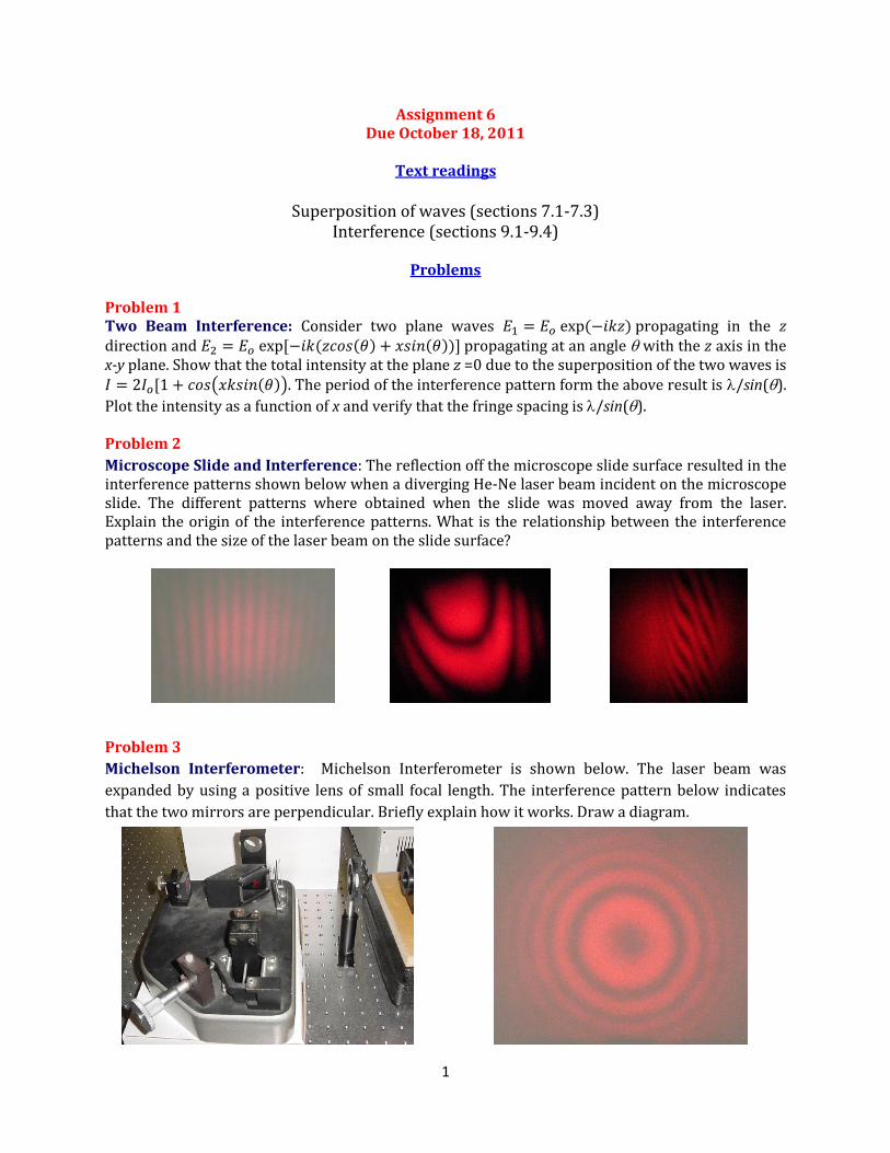
Microscope Slide and Interference: The reflection off the microscope slide surface resulted in the interference patterns shown below when a diverging He-Ne laser beam incident on the microscope slide. The different patterns where obtained when the slide was moved away from the laser. Explain the origin of the interference patterns. What is the relationship between the interference patterns and the size of the laser beam on the slide surface? Problem 3
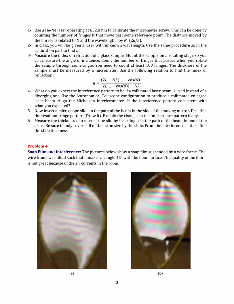
Michelson Interferometer: Michelson Interferometer is shown below. The laser beam was
expanded by using a positive lens of small focal length. The interference pattern below indicates
that the two mirrors are perpendicular. Briefly explain how it works. Draw a diagram.
2
1- Use a He-Ne laser operating at 632.8 nm to calibrate the micrometer screw. This can be done by counting the number of fringes N that move past some reference point. The distance moved by the mirror is related to N and the wavelength l by N=(2d/).
2- In class, you will be given a laser with unknown wavelength. Use the same procedure as in the calibration part to find .
3- Measure the index of refraction of a glass sample. Mount the sample on a rotating stage so you can measure the angle of incidence. Count the number of fringes that passes when you rotate the sample through some angle. You need to count at least 100 fringes. The thickness of the sample must be measured by a micrometer. Use the following relation to find the index of refraction n.
4- What do you expect the interference pattern to be if a collimated laser beam is used instead of a diverging one. Use the Astronomical Telescope configuration to produce a collimated enlarged laser beam. Align the Michelson Interferometer. Is the interference pattern consistent with what you expected?
5- Now insert a microscope slide in the path of the beam in the side of the moving mirror. Describe the resultant fringe pattern (Draw it). Explain the changes in the interference pattern if any.
6- Measure the thickness of a microscope slid by inserting it in the path of the beam in one of the arms. Be sure to only cover half of the beam size by the slide. From the interference pattern find the slide thickness.
Problem 4
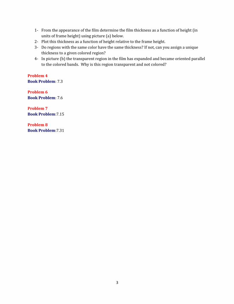
Soap Film and Interference: The pictures below show a soap film suspended by a wire frame. The
wire frame was tilted such that it makes an angle 45o with the floor surface. The quality of the film
is not great because of the air currents in the room.
(a) (b)
3
1- From the appearance of the film determine the film thickness as a function of height (in
units of frame height) using picture (a) below.
2- Plot this thickness as a function of height relative to the frame height.
3- Do regions with the same color have the same thickness? If not, can you assign a unique
thickness to a given colored region?
4- In picture (b) the transparent region in the film has expanded and became oriented parallel
to the colored bands. Why is this region transparent and not colored?