+ All Categories
Home > Documents > Superprecision Ball Bearings - Rolamentos industriais … · ABOUT THE COVER The Torrington Company...

Superprecision Ball Bearings - Rolamentos industriais … · ABOUT THE COVER The Torrington Company...

Date post: 23-Aug-2018
Category:
Upload: vanbao
View: 216 times
Download: 0 times
Share this document with a friend
168
ABOUT THE COVER The Torrington Company is committed to develop, produce and deliver products and services that consistently meet or exceed customer expectations. Helping The Torrington Company achieve the goals stated above are our corps of highly trained sales engineers, the latest analytical and manu- facturing systems, a commitment to research and development for new ideas and products, our devotion to the principles of Total Quality and a history steeped in technological firsts in the antifriction industry. This catalog will help you to design the technol- ogy, quality and service of The Torrington Company into your products. 1 ©2000 The Torrington Company Superprecision Ball Bearings
Transcript

ABOUT THE COVERThe Torrington Company is committed to develop,

produce and deliver products and services thatconsistently meet or exceed customer expectations.

Helping The Torrington Company achieve thegoals stated above are our corps of highly trainedsales engineers, the latest analytical and manu-facturing systems, a commitment to research anddevelopment for new ideas and products, ourdevotion to the principles of Total Quality and ahistory steeped in technological firsts in theantifriction industry.

This catalog will help you to design the technol-ogy, quality and service of The Torrington Companyinto your products.

1

©2000 The Torrington Company

Superprecision Ball Bearings

2 102800

FAFNIR SUPERPRECISION BEARINGS

Introduction Pages 4-5

Superprecision Bearings Pages 8-85

Ballscrew Support Bearings Pages 86-100

Engineering Pages E1-E49

Maintenance • Machine Tool Spindles Pages E51-E63

Index Pages E64-E65

CONTENTS

3102800

FAFNIR SUPERPRECISION BEARINGS

See last page of catalog for Engineering Sales Offices

INT

RO

DU

CT

ION

SU

PE

RP

RE

CIS

ION

BE

AR

ING

SB

AL

LS

CR

EW

SU

PP

OR

T B

EA

RIN

GS

EN

GIN

EE

RIN

GM

AIN

TE

NA

NC

E M

AC

HIN

ET

OO

L S

PIN

DL

ES

IND

EX

Forward E52Procedure E52Enclosed Dust-Free Working Area E52Inspection of Parts Before Assembly E52Bearing Packing E53Bearings Assembled in Spindle Mounting E53Bearings and Shaft Assembled with

Eccentricities Opposed E54Scraping Locknut to Eliminate Runout E55

Checking Temperature, Vibrationand Roughness E56

Cleanliness E56-E58Typical Applications of Ball Bearings

to Machine Tool Spindles E58Quick Reference Data Sheets E60-E62Bearing Analysis sheet E63

Forward E2Tolerances E3Standard Tolerances, Inner Ring, ABEC-7,-9 E4Width Tolerances E4Standard Tolerances, Outer Ring, ABEC-7,-9 E5Shaft and Housing Geometry E6Recommended Spindle Shaft Tolerances E8,E9Recommended Spindle Housing Tolerances E10-E15Ball Screw Shaft and Housing

Shoulder Diameters E16Spindle Shaft and Housing

Shoulder Diameters E17-E19

Locknut Torque E22Micron Bore and O.D. Coding E23Lube Inlet Diameters E27Recommended Ball Screw Shaft

and Housing Tolerances E24,E25Typical Mountings of Duplex Bearings E29Back-to-Back vs Face-to-Face Mounting E30Spring-Loaded Mountings E31Preloading E31Bearing Selection E32Bearing Spacers E34

Housing Design E34Housing Seals E35Bearing Locknuts E35Heat Generation E35,E36Permissible Operating Speed E36Lubrication Types E37,E38Engineering Notations E41Life Calculators E41-E43Life Adjustment Factors E43Applications E45-E48Radial Internal Clearance E49

Extra-Light 2MMV9100HX Series 34-41Extra-Light 2MM9100WI, 3MM9100WI Series 42-51Extra-Light MM9100K Series 52-54Light 2MM200WI, 3MM200WI Series 56-65Light MM200K Series 66-68Medium 2MM300WI, 3MM300WI Series 69-77Medium MM300K Series 78-80Ex-Cell-O Spindle Bearings 81-83Hybrid Ceramic Bearings 84,85

The Torrington Company 1The Torrington Commitment 1Fafnir Superprecision Bearings 4Using This Catalog 4Hybrid Ceramic Bearings 5Conditions of Sale 5Warranty 5Liability 5Restricted Applications 5Safety Recommendations 5

Nomenclature Chart 8Superprecision Bearing Introduction 10Machine Tool Offering Chart 11Bearing Types

Angular Contact 12Ballscrew Support Bearings 13

Ultra-Light 2MM9300WI, 3MM9300WI Series 14-23Extra-Light 2MMV99100WN,

3MM99100WN Series 24-33

Nomenclature Chart 86Ballscrew Support Bearings 88-91BSBU D

Standard and Heavy Duty Bearings 92,93BSBU Q

Standard and Heavy Duty Bearings 94,95BSPB D

Standard and Heavy Duty Bearings 96,97BSPB Q

Standard and Heavy Duty Bearings 98,99

CONTENTS

Shelf Life and Storage Policy 6

INTRODUCTION

INTRODUCTIONThe Torrington Company (hereinafter referred to as “Torrington”),part of worldwide Ingersoll-Rand, is a bearing and automotivecomponent supplier of international stature. Its global presence inNorth America, Europe, Australia, South America and the FarEast, plus joint ventures in Japan, The People’s Republic ofChina, and Europe, support customer operations around theworld.

Torrington began manufacturing bearings in the early 1900sand now produces every basic type of precision ground anti-friction bearing, as well as many precision components for othermechanisms. Torrington’s wholly owned subsidiary, KilianManufacturing Corporation, produces lighter duty machinedbearings. Torrington’s merger with Fafnir Bearing, founded in1911 and recognized as one of the world’s major suppliers ofprecision bearings and housed units, has further strengthenedTorrington’s leadership position as a broad line supplier to theworld’s industries.

Torrington’s world leadership position in an automotivecomponent technology is based on its complete technical ability.This extends from the initial design stages through applicationanalysis, to optimizing the entire manufacturing process. Theexperience gained from broad design and manufacturingactivities is available to our customers through Torrington’sresident engineers and field sales engineers in all parts of theworld.

As Torrington enters the 21st century, it has dedicated itscapabilities and resources — its people, facilities, systems andtechnologies — to two goals:

• producing world-class products.• assuring total customer satisfaction.

TORRINGTON IS AT HOME AROUND THE WORLDTo support its sales and service activities, Torrington has:• Over 20 manufacturing plants on five continents.• Over 40 district sales engineering offices throughout the

world.• Warehouses throughout the U.S.A., Canada and Germany,

with interlinking computerized inventory control.• Extensive capabilities in metric and inch bearings.• Technical resources for customer assistance.For new concepts of the future, for the challenges faced by

industry, Torrington offers in-depth design assistance andmultinational supply capability for products that are made toidentical standards worldwide.

USING THIS CATALOGWe are committed to providing our customers with maximumservice and quality. Included in this commitment is a concern forthe suitability of the bearing selected for any application. Onlythose with sufficient engineering training and technical compe-tence to interpret and apply the data and principles involvedshould make the final selection of a bearing. The part number inthis catalog describes only the dimensions. The part number ofthe product supplied may differ than those listed in these pages.

This catalog contains dimensions, tolerances and loadratings, as well as an engineering section describing fittingpractices for shafts and housings, internal clearances, materialsand other features of superprecision bearings. It is not to beconsidered as containing sufficient data for reliable bearingdesign and selection for all applications. It can, however, providevaluable assistance in the initial consideration of the type andcharacteristics of the bearing which may be most suitable forparticular needs.

Although all data in this catalog has been carefully compiledto make the information as complete as possible, Torringtonassumes no liability to any company or person for any damages,direct or indirect, to property or person, based on informationcontained in this publication.

CATALOG FEATURESDimension and load rating data for the various types and stylesof bearings is organized by size. There is also a numeric/alphalisting of product designation codes in the front of the catalog.

ISO, DIN, and “ABMA”*, as used in this catalog, refer to theInternational Organization for Standardization, Deutsches Institutfür Normung EV and the American Bearing ManufacturersAssociation.

FAFNIR SUPERPRECISION BEARINGSFafnir introduced its superprecision bearings, developedspecifically for machine tool applications, in 1935. Since that timeour engineers, designers, metallurgists and skilled machinists,utilizing state-of-the-art process technology have made improve-ments in their design, material, lubrication, and manufacturingprocesses. The result is a line of Fafnir superprecision bearingscapable of higher speeds, greater reliability, and wider versatility.

As part of our on-going research, development and testingprogram, our engineers analyze their client’s applicationproblems using sophisticated computers and software whichenable them to:

• recommend the precise type and size of bearing that willgive optimum performance under a variety of conditions.

• predict the probable service life of all bearings with consider-able accuracy.

All of the superprecision bearings listed in this catalogembody the same high standards of precision and quality whichhave made the FAFNIR name synonymous with bearingexcellence throughout the world.

The following are registered trademarks of The TorringtonCompany:

Torrington®

Fafnir®

Kilian®

Wuxi®

* Formerly the AFBMA – Anti-Friction Bearing Manufacturers Association.

1028004

INTRODUCTION

INT

RO

DU

CT

ION

HYBRID CERAMIC BEARINGSAny of the bearings offered by the Torrington Company arealso available with ceramic, silicon nitride, rolling elements.

Designed with increased speed capabilities, the hybridceramic bearing features a higher elastic modulus for graterstiffness. Its lower friction characteristics result in less skiddingthan the all-steel bearings are discussed in greater detail onpages 38 and 39.

The Torrington Company Sales Engineer in your area canassist you in determining if the hybrid ceramic bearing is suitablefor your application. They will help you to determine if hybridceramics are the answer, or if another Torrington Companyproduct is a better solution. For the location of the TorringtonCompany Sales Office in your area refer to the last page inthis catalog.

SALES ENGINEERING SERVICESSince no catalog can include or disclose all the factors necessaryfor proper bearing selection in every type of application, wehighly recommend consulting with us on any application whereproperty damage or injury to persons from misapplication shouldbe of special concern in the selection of the bearing.

Part of the Torrington world-wide service system is a corps ofhighly trained sales engineers who are available to work towardsolving new or unusual problems. Torrington may have alreadysolved a similar problem and can offer a speedy, cost-effectivesolution. The last page of this catalog lists the phone number andaddress of the Torrington office nearest you.

Torrington reserves the right to change the design and/orspecifications of its products without notice.

TERMS AND CONDITIONS OF SALEAll products described in this catalog are subject to Torrington’sTerms and Conditions of Sale, copies of which are available fromTorrington’s district offices as listed in the back of this catalog.It is understood that the buyer, in selecting and ordering from thiscatalog which supersedes all previous editions, accepts allTerms and Conditions of Sale including the following:

WARRANTYTorrington warrants that parts manufactured by it will be as

specified and will be free from defects in material and workman-ship. Torrington’s liability under this warranty shall be limited tothe repair or replacement or the repayment of the purchase price,or the granting of a reasonable allowance (as Torrington mayelect) of any part which upon return to Torrington is found to bedefective at the time of shipment, providing the buyer notifiesTorrington of any such defect within 10 days of its discovery, butin no event later than 90 days from the date of shipment of suchpart by Torrington. Repair or replacement shall be made byTorrington F.O.B. point of shipment.

Seller makes no other warranty or representation of anykind whatsoever, expressed, or implied, except that of titleand all implied warranties, including any warranty of mer-chantability or fitness for a particular purpose, are herebydisclaimed.

LIABILITYTotal liability of Torrington with respect to any order, whether

based on contract, warranty, negligence, indemnity, strict liabilityor otherwise, shall not exceed the purchase price of the partupon which such liability is based.

Torrington shall in no event be liable to the buyer, anysuccessors in interest or any beneficiary of any order, for anyconsequential, incidental, indirect, special or punitive damagesarising out of such order or any breach thereof, whether or notsuch loss or damage is based on contract, warranty, negligence,indemnity, strict liability or otherwise.

NUCLEAR APPLICATIONThe bearings described within this catalog are not intended

for nuclear application. Should any such application be consid-ered, it is urged that you consult with Torrington.

For use within any nuclear facility, Owner/Licensee of thenuclear facility and/or buyer shall indemnify and hold Torringtonharmless from any liability occurring on or off-site, at any time,including loss of use, whether based in contract or tort, includingnegligence attributable in whole or in part to Torrington, resultingdirectly or indirectly from a nuclear incident.

HELICOPTER APPLICATIONTorrington has discontinued offering it’s products to the

helicopter industry. This includes bearings previously sold tothe helicopter industry under the Torrington, Fafnir and Kiliantrade names. As a result of this decision, Torrington will nolonger provide engineering support nor recommend thatTorrington bearings be used in helicopter applications.

With regard to aircraft bearings manufactured to militarystandards, only the aircraft/helicopter manufacturer can deter-mine if the aircraft mil spec bearings are suitable for usein its aircraft.

SAFETY RECOMMENDATIONS• Product should be stored in a dry and clean area.• Package should not be opened until ready to use.• Prior to installation, Torrington should be consulted for

recommendations. Proper installation and maintenancemust be adhered to for ultimate performance.

• Failure to adhere to recommendations may result inpremature product failure, and/or in extreme cases,personal injury.

5102800

INTRODUCTION

6 102800

STORAGE POLICY:The Torrington policy recommends the following storageguidelines for its finished products (bearings, components,and assemblies, hereinafter the “Products”):

© Unless directed otherwise by The Torrington Company,Products should be kept in their original packaging untilthey are ready to be placed into service.

© Do not remove or alter any labels or stencil markings onthe packaging.

© Products should be stored in such a way that thepackaging is not pierced, crushed or otherwise damaged.

© After a Product is removed from its packaging, it shouldbe placed into service as soon as possible.

© When removing a Product that is not individually pack-aged from a bulk pack container, the container should beresealed immediately after the Product is removed.

© Do not use Product that has exceeded its Shelf Life asdefined in Torrington’s Shelf Life Policy Statement.

© The storage area temperature should be maintainedbetween 0° C (32° F) and 40° C (104° F); temperaturefluctuations should be minimized.

© The relative humidity should be maintained below 60%.

© The storage area should be kept free from airbornecontaminants such as, but not limited to: dust, dirt,harmful vapors, etc.

© The storage area should be isolated from undue vibration.

© Extreme conditions of any kind should be avoided.

In as much as The Torrington Company is not familiarwith a customer’s particular storage conditions, theseguidelines are strongly recommended. However, thecustomer may very well be required by circumstance,applicable government requirements, and the like toadhere to stricter storage requirements.

FAILURE TO FOLLOW THESE GUIDELINES MAYRESULT IN REDUCED PRODUCT SHELF LIFE AND/ORADVERSELY AFFECT PRODUCT PERFORMANCE.

Any questions concerning the Shelf Life or Storage Policyshould be directed to the local District Sales Office.

SHELF LIFE AND STORAGE OF GREASELUBRICATED BEARINGS AND COMPONENTS

SHELF LIFE POLICY:The Torrington Policy for the Shelf Life of Grease Lubri-cated Rolling Element Bearings, Components and assem-blies is set forth below. The Shelf Life values are based ontest data and experience.

Shelf Life should be distinguished from lubricatedbearing/component Service Life as follows:

Shelf LifeThe Shelf Life of the grease lubricated bearing/compo-

nent is the maximum allowable time interval from date oforiginal manufacture/packaging to the removal from theoriginal packaging (hereinafter referred to as “Shelf Life”).

Service LifeThe Service Life of the grease lubricated bearing/compo-

nent is a measure of the anticipated aggregate usage(hereinafter referred as “Service Life”). Variations in lubri-cant bleed rates, oil migration, operating conditions, installa-tion conditions, temperature, humidity and extended storagemake it impossible to accurately predict Service Life.

The Bearing Shelf Life is related primarily to thelubricant’s ability to maintain the bearing’s original manu-factured radial internal clearance and freedom to rotate.

The Component Shelf Life is related to the ability of thecomponent to function as originally intended.

The Shelf Life values, available from the TorringtonDistrict Sales Office, represent the period of time prior touse or installation. Due to the broad range of applications,Torrington cannot anticipate the performance of the greaselubricant after the bearing or component is installed orplaced in service.

These Shelf Life values are to be used as a maximumlimit – assuming adherence to the Torrington recom-mended storage and handling policy. Deviations fromTorrington’s Storage and Handling Policy may reduce ShelfLife. Any specification or operating practice that defines ashorter Shelf Life should be used.

THE BEARING/COMPONENT SHOULD NOT BE PUTINTO SERVICE IF THIS SHELF LIFE IS EXCEEDED.

TORRINGTON DISCLAIMS RESPONSIBILITY FOR THESHELF LIFE OF ANY BEARING/COMPONENT LUBRI-CATED BY ANOTHER PARTY.

INTRODUCTION

INT

RO

DU

CT

ION

7102800

HybridCeramic

Series:9300 ultra light9100 extra light

99100 extra light200 light300 medium

Bore Size:(04 and up,multiply theselast two numbersby 5 to get borein millimeters:)00 10mm01 12mm02 15mm03 17mm04 20mm

an exampleof a specif-icationnumber forother thanstandard

2 MM C 91 04 WI CR DUL A3188

Superprecision Ball Bearings

H, R, J, P† internal fit† P fit is standard in Conrad BearingsContact Angle:

2 = 15°3 = 25°

Construction:K Conrad

WI angular contact; low shoulder on outer ringWO angular contact; low shoulder on inner ringWN angular contact; low shoulder on both ringsHX angular contact; low shoulder on both rings

Level of Precision:MM superprecision • ABEC-7 (ISO P4)

MMV super high precision (HG) between ABEC-7(ISO P4) and ABEC-9 (ISO P2)

MMX ultraprecision • ABEC-9 (ISO P2)

Retainer: No retainer callout impliesFafnir PRC

PRB molded nylon cagePRC molded reinforced nylon cage

CR phenolic (composition) – Fafnir standard

102800

Preload: Universal Flush Ground*SUX single bearing, extra light*SUL single bearing, light*SUM single bearing, medium*SUH single bearing, heavyDUX duplex pairs of bearings, extra lightDUL duplex pairs of bearings, lightDUM duplex pairs of bearings, mediumDUH duplex pairs of bearings, heavyTUX triplex set of bearings, extra lightTUL triplex set of bearings, lightTUM triplex set of bearings, mediumTUH triplex set of bearings, heavyQUX quadruplex set of bearings, extra lightQUL quadruplex set of bearings, lightQUM quadruplex set of bearings, mediumQUH quadruplex set of bearings, heavy

* if "u" is first letter here, assume single

8

9

FAFNIR SUPERPRECISION BEARINGS

SU

PE

RP

RE

CIS

ION

BE

AR

ING

S

102800

10 102800

FAFNIR SUPERPRECISION BEARINGS

Superprecision MM (ABEC-7, ISO P4)Superprecision bearings of the K or non-filling slot con-struction are generally used on woodworking spindles,aircraft accessory units and machine tool applicationswhere duplex bearings are not a definite requirement.By virtue of the single row radial deep groove constructionand superprecision tolerances, they are capable of carryingthrust loads in either direction and have relatively high-speed ability.

More popular on precision machine tool spindle applica-tions are the WI angular-contact type bearing variations,namely 2MM-WI and 3MM-WI. Since this bearing typehas a low shoulder on outer ring, it carries thrust in onedirection.

Fafnir's MM Superprecision bearings are finished toMMV tolerances – as standard procedure.

Super High Precision MMV (HG)Superprecision bearings are manufactured to our new HGtolerance class, with running accuracy and performancemeeting ABEC-9 (ISO P2) while maintaining noncriticalfeatures at ABEC-7 (ISO P4) level for cost-effectiveness.Bore and O.D. surfaces are coded in micron units for theconvenience of the discriminating machine tool builder whois striving for optimum fitting of all spindle components.

The recent development of ceramic rolling elements inhigh performance bearings offers the customer the ultimateof speed capability, high stiffness, long life, low heatgeneration, and overall system reliability. The 99100 seriesis available with the option of ceramic ball selection.

Ultraprecision MMX (ABEC-9, ISO P2)Superprecision bearings with closer tolerances and runningaccuracies than ABEC-7 (ISO P4) bearings are made toABEC-9 (ISO P2) tolerances. Bearings produced to thesetolerances are generally made as WO and WN construc-tion, and are use on ultra-high speed grinding spindlesdesigned for tight dimensional tolerances and super-finesurface finishes. Consult our Engineering Department foravailability.

11102800

FAFNIR SUPERPRECISION BEARINGS

SU

PE

RP

RE

CIS

ION

BE

AR

ING

S

MACHINE TOOL BEARING PRODUCT RANGE*Bore Size (mm)

10 20 30 40 50 60 70 80 90 100 110 120 130 140 150 160 170 180 190 200

*Current product offering range. For sizes not found within this listing, check with the TorringtonEngineering Department for design possibilities.

MM9300 (MM . . . BS)Pages 88-91

2MM(3MM)9300WIPages 14-23

MM9100KPages 52-54

2MM(3MM)9100WIPages 42-51

2MM(3MM)V9100HXPages 34-41

MM200KPages 66-68

2MM(3MM)200WIPages 56-65

MM300KPages 78-80

2MM(3MM)300WIPages 69-77

TYPE

SPINDLE BEARINGS

BALL SCREW SUPPORT BEARINGS

12 102800

FAFNIR SUPERPRECISION BEARINGSFAFNIR SUPERPRECISION BEARINGS

Bearing Types

Angular-Contact Bearings2MM -WI type , with 15° initial contact angle is designed tomeet the needs of machine builders for precision bearingswhich will operate at as low a temperature as possible for awide range of speeds and operating loads. In order formachines to produce more accurate work at a higher produc-tion rate, the bearings must provide a high degree of rigidity inboth axial and radial directions while operating at minimumtemperatures. For example, precision machining or cuttingtools impose heavier loads on bearings than those encoun-tered in precision grinding. In the former, speeds are slowerand loads heavier than the latter, where speeds are high andloads light. The 2MM-WI type gives the machine builder theflexibility required to meet such variations in applications.3MM -WI type , manufactured with 25° contact angle,is for use on applications where the loading on the bearings ispredominately thrust — and a high degree of axial rigidity is adefinite requirement. Typical applications for these are largevertical rotary surface grinders, horizontal and vertical discgrinders, and thrust bearing applications for heavy duty latheswhere the bearings must directly carry extremely high tail stockor chucking pressure.

2MM -WO type , with 15° initial contact angle is designed forextremely high-speed applications where centrifugal force ofthe balls is the principal load on the bearing. Unlike the MM-WItype which has a low shoulder outer ring, the 2MM-WO typehas full shoulders on both sides of the outer race and a lowshoulder on one side of the inner ring. This design permitsassembly with a maximum complement of balls and a one-piece cage which pilots against the precision-ground lands ofthe outer ring. Generally this bearing series is supplied with aseparable inner ring and ball retaining cage along with specialrace geometry for extremely high speed operation.

2MMV and 3MMV99100WN types are available with 15° or25° contact angle variations and have been developed tooperate under the demanding requirements of high speedmachine tools. They incorporate design features which permitoperation at higher speed than standard angular contact ballbearings. The bore, outside diameter, and width are the sameas the MM9100 series.

This series is designed to operate at rotational speeds 20%greater than the MM9100 series, with no increase in operatingtemperature. The greatest advantage of these series is atspeeds greater than 500,000 DN (Bore in mm x RPM). Siliconnitride balls (ceramic) and precision machined ball separatorsare available and, when used, the ultimate performance will beachieved.

2MM-WI Type

3MM-WI Type

2MM-WO Type

2MMV and3MMV99100WN Types

13102800

FAFNIR SUPERPRECISION BEARINGS

MM9300WI DUH (Inch)MM…BS…DUH (Metric)

FAFNIR SUPERPRECISION BEARINGS

SU

PE

RP

RE

CIS

ION

BE

AR

ING

S

2MMV - HX type , with 15° initial contact angle is designed tomeet the needs of machine manufacturers who requireoptimum oil flow through the bearings. This design incorpo-rates a low shoulder on the non-thrust side of both the innerand outer rings. The maximum complement of balls isseparated by a one-piece cage which pilots against theground land of the outer ring.

Fafnir has developed an ISO Series – 10 bearing designedto enhance two key factors contributing to metalworkingthroughput: spindle speed and radial stiffness.

This design enables spindle heads to remove morematerial in less time while maintaining superior finishedproduct tolerances by minimizing tool “wander”. This efficientcombination translates into faster turn around of finishedproduct. These improvements are imparted by subtlechanges to ball complements and internal geometriesconcluded by Fafnir design engineers as being a reliable pathtoward better machining efficiencies.

The Fafnir HX Series is dimensionally interchangeablewith our present 9100 and 99100 series spindle bearingsalong with competitive ISO Series-10 designs.

Ballscrew Support BearingsTo meet the requirements of the servo-controlled machineryfield, Torrington has developed a new series of ball bearingsspecially designed for ballscrew applications. Design criteriafor these bearings are maximum axial rigidity, low dragtorque, and extreme control of lateral eccentricity.

These bearings are manufactured to ABEC-7 tolerancesand are of the nonseparable angular-contact type design witha 60° contact angle and maximum complement of balls.Thesebearings are supplied prelubricated with heavy duty greaseNLGI #2 . Bearings are supplied packaged in DB arrange-ment. However, they can be mounted in duplexed pairs andin multiplexed sets in either Back-to-Back (DB), Face-to-Face(DF) or Tandem (DT) arrangements.

Standard sizes are available and are stocked and pack-aged as duplex pairs, triplex sets or quadruplex sets. Thesebearings are designed primarily for ballscrew applications andshould not be considered in other areas such as spindles orgear-box shafting without approval by our EngineeringDepartment. These bearings are offered in both standard inchand metric envelope dimensions.

2MMV-HX Type

14 102800

FAFNIR SUPERPRECISION BEARINGS

DIMENSIONS – TOLERANCES ALL INCH TOLERANCE IN .0001 UNITSBearing Outside Maximum BallNumber Bore Diameter Width * Fillet Radius Complement

Tolerance Tolerance Tolerance Bearing Corner+.0000" +.0000" +.0000" will Clear **+.0 µm +.0 µm +.0 µm

2MM & 3MM to minus to minus to minus

in. mm in. µm in. mm in. µm in. mm in. µm in. mm Qty. (Dia.) in.

9300WI 0.3937 10 1.5 4 0.8661 22 2.0 5 0.2362 6 16 40 0.012 0.3 12 1⁄89301WI 0.4724 12 1.5 4 0.9449 24 2.0 5 0.2362 6 31 80 0.012 0.3 13 1⁄89302WI 0.5906 15 1.5 4 1.1024 28 2.0 5 0.2756 7 31 80 0.012 0.3 13 9⁄649303WI 0.6693 17 1.5 4 1.1811 30 2.0 5 0.2756 7 31 80 0.012 0.3 14 9⁄649304WI 0.7874 20 2.0 5 1.4567 37 2.5 6 0.3543 9 47 120 0.012 0.3 14 3⁄16

9305WI 0.9843 25 2.0 5 1.6535 42 2.5 6 0.3543 9 47 120 0.012 0.3 17 3⁄169306WI 1.1811 30 2.0 5 1.8504 47 2.5 6 0.3543 9 47 120 0.012 0.3 19 3⁄169307WI 1.3780 35 2.5 6 2.1654 55 3.0 7 0.3937 10 47 120 0.024 0.6 19 7⁄329308WI 1.5748 40 2.5 6 2.4409 62 3.0 7 0.4724 12 47 120 0.024 0.6 19 1⁄49309WI 1.7717 45 2.5 6 2.6772 68 3.0 7 0.4724 12 47 120 0.024 0.6 21 1⁄4

9310WI 1.9685 50 2.5 6 2.8346 72 3.0 7 0.4724 12 47 120 0.024 0.6 23 1⁄49311WI 2.1654 55 3.0 7 3.1496 80 3.0 7 0.5118 13 59 150 0.039 1.0 23 9⁄ 329312WI 2.3622 60 3.0 7 3.3465 85 3.0 8 0.5118 13 59 150 0.039 1.0 25 9⁄ 329313WI 2.5591 65 3.0 7 3.5433 90 3.0 8 0.5118 13 59 150 0.039 1.0 27 9⁄ 32

9314WI 2.7559 70 3.0 7 3.9370 100 3.0 8 0.6299 16 59 150 0.039 1.0 24 11⁄ 32

* Refer to page E4 for width tolerance of preloaded bearings.** ABMA std. 20 (ras max).

Ultra-Light2MM9300WI &3MM9300WI Series

TO ORDER: Specify bearing number with prefix 2MM for 15 ° contactangle and 3MM for 25 ° contact angle.

Example 2MM9300WI CR

Dd

C

C

Superprecision MM:Superprecision bearings are manufactured to a ABEC-7(ISO P4) tolerance class.

WI Construction:This design incorporates a low shoulder on the non-thrustside of the outer rings. The maximum complement of ballsis separated by a one-piece cage which is piloted againstthe ground thrust shoulder land of the outer ring.

15102800

FAFNIR SUPERPRECISION BEARINGS

SU

PE

RP

RE

CIS

ION

BE

AR

ING

S

DIMENSIONS – TOLERANCES ALL INCH TOLERANCE IN .0001 UNITSBearing Outside Maximum BallNumber Bore Diameter Width * Fillet Radius Complement

Tolerance Tolerance Tolerance Bearing Corner+.0000" +.0000" +.0000" will Clear **+.0 µm +.0 µm +.0 µm

2MM & 3MM to minus to minus to minus

in. mm in. µm in. mm in. µm in. mm in. µm in. mm Qty. (Dia.) in.

9315WI 2.9528 75 3.0 7 4.1339 105 3.0 8 0.6299 16 59 150 0.039 1.0 25 11⁄329316WI 3.1496 80 3.0 7 4.3307 110 3.0 8 0.6299 16 59 150 0.039 1.0 27 11⁄329317WI 3.3465 85 3.0 8 4.7244 120 3.0 8 0.7087 18 79 200 0.039 1.0 26 3⁄89318WI 3.5433 90 3.0 8 4.9213 125 3.5 9 0.7087 18 79 200 0.039 1.0 26 13⁄329319WI 3.7402 95 3.0 8 5.1181 130 3.5 9 0.7087 18 79 200 0.039 1.0 28 13⁄32

9320WI 3.9370 100 3.0 8 5.5118 140 3.5 9 0.7874 20 79 200 0.039 1.0 29 13⁄329322WI 4.3307 110 3.0 8 5.9055 150 3.5 9 0.7874 20 79 200 0.039 1.0 31 13⁄329324WI 4.7244 120 3.0 8 6.4961 165 4.0 10 0.8661 22 79 200 0.039 1.0 30 15⁄ 329326WI 5.1181 130 4.0 10 7.0866 180 4.0 10 0.9449 24 98 250 0.059 1.5 30 17⁄ 329328WI 5.5118 140 4.0 10 7.4803 190 4.5 11 0.9449 24 98 250 0.059 1.5 32 17⁄ 32

9330WI 5.9055 150 4.0 10 8.2677 210 4.5 11 1.1024 28 98 250 0.079 2.0 27 11⁄ 169332WI 6.2992 160 4.0 10 8.6614 220 4.5 11 1.1024 28 98 250 0.079 2.0 27 23⁄ 329334WI 6.6929 170 4.0 10 9.0551 230 4.5 11 1.1024 28 98 250 0.079 2.0 29 23⁄ 32

9340WI 7.8740 200 4.5 12 11.0236 280 5.0 13 1.4961 38 118 300 0.083 2.1 27 15⁄ 16

* Refer to page E4 for width tolerance of preloaded bearings.** ABMA std. 20 (ras max).

C (WIDTH) X 2

d DD d D d D

C (WIDTH) X 2

C (WIDTH) X 2

Back-to-Back Face-to-Face TandemDB DF DT

WI Type Duplex Mounting Arrangements

16 102800

FAFNIR SUPERPRECISION BEARINGS

PHYSICAL CHARACTERISTICS – LOAD RATINGSBearing Weight Static Extended Permis- Preload LevelsNumber Per Bearing Load Rating Dynamic sible

Load Ratings SpeedCo Ce Ng * Extralight (1) Light Medium Heavy

(DUX) (DUL) (DUM) (DUH)

lbs kg lbs N lbs N RPM lbs N lbs N lbs N lbs N

2MM9300WI 0.02 0.010 285 1,300 735 3,300 77,500 — — 3 15 6 25 12 552MM9301WI 0.03 0.011 320 1,400 765 3,400 67,200 — — 3 15 6 25 12 552MM9302WI 0.04 0.016 415 1,800 950 4,200 55,600 — — 5 20 10 45 20 902MM9303WI 0.04 0.018 490 2,200 1,040 4,600 50,100 — — 5 20 15 65 30 1302MM9304WI 0.08 0.037 780 3,500 1,700 7,600 42,100 — — 10 45 20 90 35 160

2MM9305WI 0.10 0.043 1,000 4,400 1,900 8,500 34,800 — — 10 45 25 110 40 1802MM9306WI 0.11 0.050 1,140 5,100 2,000 8,900 29,700 — — 10 45 25 110 40 1802MM9307WI 0.17 0.077 1,560 6,900 2,600 11,600 25,400 — — 10 45 25 110 55 2402MM9308WI 0.25 0.112 2,040 9,100 3,350 14,900 22,400 5 30 15 65 35 160 70 3102MM9309WI 0.29 0.133 2,280 10,100 3,450 15,300 20,000 10 30 20 90 40 180 80 360

2MM9310WI 0.30 0.135 2,550 11,300 3,650 16,200 18,300 10 40 20 90 45 200 90 4002MM9311WI 0.41 0.187 3,200 14,200 4,550 20,200 16,600 10 40 25 110 55 240 110 4902MM9312WI 0.44 0.200 3,450 15,300 4,750 21,100 15,300 10 40 25 110 55 240 115 5102MM9313WI 0.47 0.215 3,750 16,700 4,900 21,800 14,200 15 70 30 130 60 270 120 5302MM9314WI 0.76 0.344 5,000 22,200 6,700 29,800 13,100 15 70 40 180 80 360 160 710

2MM9315WI 0.80 0.363 5,200 23,100 6,800 30,200 12,300 20 90 40 180 85 380 170 7602MM9316WI 0.85 0.385 5,600 24,900 7,100 31,600 11,600 20 90 45 200 90 400 180 8002MM9317WI 1.23 0.556 6,550 29,100 8,150 36,300 10,800 25 110 60 270 120 530 240 10702MM9318WI 1.26 0.573 7,650 34,000 9,500 42,300 10,300 25 110 60 270 120 530 240 10702MM9319WI 1.33 0.601 8,150 36,300 9,800 43,600 9,800 30 130 65 290 130 580 260 1160

2MM9320WI 1.87 0.846 8,300 36,900 9,800 43,600 9,100 30 130 80 360 160 710 330 14702MM9322WI 2.02 0.918 8,800 39,100 10,200 45,400 8,400 40 180 90 400 180 800 360 16002MM9324WI 2.74 1.243 11,600 51,600 12,900 57,400 7,700 45 200 110 490 220 980 440 19602MM9326WI 3.63 1.648 15,000 66,700 16,300 72,500 7,100 50 220 140 620 275 1220 550 24502MM9328WI 3.85 1.746 15,600 69,400 17,000 75,600 6,600 60 270 140 620 280 1250 575 2560

2MM9330WI 5.75 2.609 22,000 97,400 25,000 111,200 6,200 65 290 190 850 380 1690 775 34502MM9332WI 6.06 2.749 32,200 143,100 29,000 128,900 5,800 110 489 220 980 445 1980 890 39602MM9334WI 6.34 2.875 26,000 115,600 28,000 124,500 5,500 80 360 230 1020 460 2050 900 40002MM9340WI 13.87 6.291 54,700 243,300 47,100 209,500 4,600 175 778 350 1560 700 3110 1400 6230

* Limits shown for grease lubricated, single bearing, spring preloaded.(1) Call for availability.

Ultra-Light2MM9300WI Series

RADIAL LOAD RATING AT 33 1⁄3 RPMBased on 1500 hours L 10 Life and Permissible Speed

17102800

FAFNIR SUPERPRECISION BEARINGS

FREQUENCY COEFFICIENTSBearing FTF BSF BPFO BPFI FTFNumber

Fundamental Train Ball Spin Ball Pass Frequency Ball Pass Frequency Fundamental TrainFrequency Frequency Outer Inner Frequency

(Inner Rotation) (Outer Rotation)

2MM9300WI 0.4054 2.4294 4.8649 7.1351 0.59462MM9301WI 0.4159 2.7546 5.4070 7.5930 0.58412MM9302WI 0.4204 2.9335 5.4650 7.5350 0.57962MM9303WI 0.4272 3.2198 6.4074 8.5926 0.57282MM9304WI 0.4194 2.9144 5.8719 8.1281 0.5806

2MM9305WI 0.4314 3.4509 7.3346 9.6654 0.56862MM9306WI 0.4404 3.9846 8.3667 10.6333 0.55962MM9307WI 0.4405 3.9924 8.3695 10.6305 0.55952MM9308WI 0.4399 3.9578 8.3586 10.6414 0.56012MM9309WI 0.4458 4.3966 9.3612 11.6388 0.5542

2MM9310WI 0.4498 4.7547 10.3448 12.6552 0.55022MM9311WI 0.4490 4.6752 10.3262 12.6738 0.55102MM9312WI 0.4525 5.0286 11.3121 13.6879 0.54752MM9313WI 0.4556 5.3816 12.2999 14.7001 0.54442MM9314WI 0.4504 4.8196 10.8092 13.1908 0.5496

2MM9315WI 0.4531 5.1086 11.3285 13.6715 0.54692MM9316WI 0.4556 5.3974 12.3014 14.6986 0.54442MM9317WI 0.4557 5.3371 11.8322 14.1678 0.54492MM9318WI 0.4537 5.1643 11.7957 14.2043 0.54632MM9319WI 0.4557 5.4085 12.7607 15.2393 0.5443

2MM9320WI 0.4585 5.7746 13.2966 15.7034 0.54152MM9322WI 0.4617 6.2622 14.3126 16.6874 0.53832MM9324WI 0.4596 5.9438 13.7888 16.2112 0.54042MM9326WI 0.4580 5.7028 13.7392 16.2608 0.54202MM9328WI 0.4605 6.0759 14.7367 17.2633 0.5395

2MM9330WI 0.4531 5.1086 12.2348 14.7652 0.54692MM9332WI 0.4536 5.1589 12.2480 14.7520 0.54642MM9334WI 0.4559 5.4349 13.2209 15.7791 0.54412MM9340WI 0.4521 4.9931 12.2062 14.7938 0.5479

Ultra-Light2MM9300WI Series

SU

PE

RP

RE

CIS

ION

BE

AR

ING

S

Superprecision Bearings

FTF Fundamental Train Frequency: The frequency atwhich the retainer will operate.

BSF Ball Spin Frequency: The frequency at which asingle defect on a rolling element will be detected.

BPFO Ball Pass Frequency Outer: The frequency atwhich a single defect in the outer race will bedetected.

BPFI Ball Pass Frequency Inner: The frequency atwhich a single defect in the inner race will bedetected.

18 102800

FAFNIR SUPERPRECISION BEARINGS

PHYSICAL CHARACTERISTICS – LOAD RATINGSBearing Weight Static Extended Permis- Preload LevelsNumber Per Bearing Load Rating Dynamic sible

Load Ratings SpeedCo Ce Ng * Extralight Light Medium Heavy

(DUX) (DUL) (DUM) (DUH)

lbs kg lbs N lbs N RPM lbs N lbs N lbs N lbs N

3MM9300WI 0.02 0.010 360 1,580 760 3,380 69,800 — — 5 20 10 45 20 903MM9302WI 0.04 0.016 510 2,280 980 4,360 50,000 — — 10 45 20 90 35 1603MM9303WI 0.04 0.018 600 2,680 1,070 4,740 45,100 — — 10 45 30 130 55 2403MM9305WI 0.10 0.043 1,230 5,500 1,930 8,600 31,300 — — 15 65 40 180 70 310

3MM9306WI 0.11 0.050 1,080 4,800 1,900 8,500 26,700 — — 15 70 40 180 70 3103MM9307WI 0.17 0.077 1,460 6,500 2,500 11,100 22,900 — — 20 90 55 240 95 4203MM9308WI 0.25 0.112 1,930 8,600 3,150 14,000 20,200 — — 30 130 70 310 125 5603MM9309WI 0.29 0.133 2,160 9,600 3,350 14,900 18,000 — — 35 160 80 360 150 670

3MM9310WI 0.30 0.135 2,400 10,700 3,450 15,300 16,500 — — 35 160 90 400 150 6703MM9311WI 0.41 0.187 3,000 13,300 4,300 19,100 14,900 — — 45 200 110 490 190 8503MM9312WI 0.44 0.200 3,250 14,500 4,500 20,000 13,800 — — 45 200 115 510 200 8903MM9313WI 0.47 0.214 3,550 15,800 4,650 20,700 12,800 — — 50 220 120 530 240 10703MM9314WI 0.76 0.344 4,750 21,100 6,300 28,000 11,800 — — 65 290 160 710 290 1290

3MM9315WI 0.80 0.363 4,900 21,800 6,400 28,500 11,100 — — 70 310 170 760 300 13303MM9316WI 0.85 0.385 5,200 23,100 6,700 29,800 10,400 — — 75 330 180 800 310 13803MM9317WI 1.22 0.555 6,000 26,700 7,650 34,000 9,700 — — 100 440 240 1070 420 18703MM9318WI 1.26 0.572 7,100 31,600 8,800 39,100 9,300 — — 90 400 210 930 375 16703MM9319WI 1.32 0.601 7,650 34,000 9,300 41,400 8,800 — — 105 470 260 1160 450 2000

3MM9320WI 1.86 0.846 7,800 34,700 9,300 41,400 8,200 — — 135 600 330 1470 575 25603MM9322WI 2.02 0.917 8,300 36,900 9,500 42,300 7,600 — — 150 670 360 1600 625 27803MM9324WI 2.74 1.242 10,800 48,000 12,200 54,300 6,900 — — 180 800 440 1960 775 34503MM9326WI 3.63 1.647 14,000 62,300 15,600 69,400 6,400 — — 230 1020 550 2450 975 43403MM9328WI 3.85 1.744 14,600 64,900 16,000 71,200 5,900 — — 240 1070 575 2560 1000 4450

3MM9330WI 5.75 2.607 21,200 94,300 23,600 105,000 5,600 — — 325 1450 775 3450 1350 60003MM9334WI 6.33 2.871 24,500 109,000 26,000 115,600 5,000 — — — — — — — —3MM9340WI 13.87 6.291 51,400 228,500 44,400 197,500 4,100 — — 700 3110 1400 6230 2800 12460

* Limits shown for a single row, spring preloaded and grease lubricated bearing.

Ultra-Light3MM9300WI Series

RADIAL LOAD RATING AT 33 1⁄3 RPMBased on 1500 hours L 10 Life and Permissible Speed

19102800

FAFNIR SUPERPRECISION BEARINGS

FREQUENCY COEFFICIENTS

Bearing FTF BSF BPFO BPFI FTFNumber Fundamental Train Ball Spin Ball Pass Frequency Ball Pass Frequency Fundamental Train

Frequency Frequency Outer Inner Frequency(Inner Rotation) (Outer Rotation)

3MM9300WI 0.4100 2.4380 4.9204 7.0796 0.59003MM9302WI 0.4248 2.9417 5.5225 7.4775 0.57523MM9303WI 0.4312 3.2273 6.4681 8.5319 0.56883MM9305WI 0.4356 3.4586 7.4044 9.5956 0.5644

3MM9306WI 0.4439 3.9913 8.4346 10.5654 0.55613MM9307WI 0.4440 3.9990 8.4366 10.5634 0.55603MM9308WI 0.4437 3.9648 8.4295 10.5705 0.55633MM9309WI 0.4491 4.4029 9.4320 11.5680 0.5509

3MM9310WI 0.4529 4.7606 10.4166 12.5834 0.54713MM9311WI 0.4521 4.6811 10.3983 12.6017 0.54793MM9312WI 0.4554 5.0340 11.3851 13.6149 0.54463MM9313WI 0.4583 5.3867 12.3736 14.6264 0.54173MM9314WI 0.4535 4.8255 10.8839 13.1161 0.5465

3MM9315WI 0.4561 5.1141 11.4020 13.5980 0.54393MM9316WI 0.4584 5.4026 12.3766 14.6234 0.54163MM9317WI 0.4579 5.3423 11.9047 14.0953 0.54213MM9318WI 0.4565 5.1696 11.8699 14.1301 0.54353MM9319WI 0.4585 5.4136 12.8371 15.1629 0.5415

3MM9320WI 0.4611 5.7794 13.3708 15.6292 0.53893MM9322WI 0.4641 6.2666 14.3858 16.6142 0.53593MM9324WI 0.4622 5.9485 13.8645 16.1355 0.53783MM9326WI 0.4606 5.7077 13.8171 16.1829 0.53943MM9328WI 0.4630 6.0804 14.8147 17.1853 0.5370

3MM9330WI 0.4561 5.1141 12.3141 14.6859 0.54393MM9334WI 0.4586 5.4401 13.3007 15.6993 0.54143MM9340WI 0.4551 4.9987 12.2879 14.7121 0.5449

Ultra-Light3MM9300WI Series

Superprecision Bearings

FTF Fundamental Train Frequency: The frequency atwhich the retainer will operate.

BSF Ball Spin Frequency: The frequency at which asingle defect on a rolling element will be detected.

BPFO Ball Pass Frequency Outer: The frequency atwhich a single defect in the outer race will bedetected.

BPFI Ball Pass Frequency Inner: The frequency atwhich a single defect in the inner race will bedetected.

SU

PE

RP

RE

CIS

ION

BE

AR

ING

S

20 102800

FAFNIR SUPERPRECISION BEARINGS

PERMISSIBLE OPERATING SPEEDS – RPM2MM & 3MM Superprecision Angular Contact Spindle Bearings

GREASE OIL

“DB” Mounting Grease Capacity Kluber Isoflex NBU 15 “DB” Mounting15 Degree (DUL) (DUM) (DUH) 25 % 40 % 15 % 20 % (DUL) (DUM) (DUH)

Contact Angle Light Medium Heavy (grams) (grams) (grams) (grams) Light Medium Heavy

2MM9300WI 62,000 46,500 31,000 0.09 0.15 0.06 0.08 105,400 79,100 52,7002MM9301WI 53,800 40,300 26,900 0.11 0.17 0.07 0.10 91,500 68,500 45,7002MM9302WI 44,500 33,400 22,200 0.17 0.28 0.12 0.15 75,700 56,800 37,7002MM9303WI 40,100 30,100 20,000 0.19 0.30 0.12 0.16 68,200 51,200 34,0002MM9304WI 33,700 25,300 16,800 0.4 0.6 0.25 0.34 57,300 43,000 28,600

2MM9305WI 27,800 20,900 13,900 0.4 0.7 0.29 0.39 47,300 35,500 23,6002MM9306WI 23,800 17,800 11,900 0.5 0.8 0.34 0.45 40,500 30,300 20,2002MM9307WI 20,300 15,200 10,200 0.8 1.2 0.51 0.68 34,500 25,800 17,3002MM9308WI 17,900 13,400 9,000 1.2 1.9 0.80 1.07 30,400 22,800 15,3002MM9309WI 16,000 12,000 8,000 1.3 2.1 0.88 1.18 27,200 20,400 13,600

2MM9310WI 14,600 11,000 7,300 1.4 2.3 0.95 1.27 24,800 18,700 12,4002MM9311WI 13,300 10,000 6,600 1.9 3.0 1.3 1.7 22,600 17,000 11,2002MM9312WI 12,200 9,200 6,100 2.0 3.2 1.4 1.8 20,700 15,600 10,4002MM9313WI 11,400 8,500 5,700 2.1 3.4 1.4 1.9 19,400 14,500 9,7002MM9314WI 10,500 7,900 5,200 3.6 5.7 2.4 3.2 17,900 13,400 8,800

2MM9315WI 9,800 7,400 4,900 3.8 6.1 2.5 3.4 16,700 12,600 8,3002MM9316WI 9,300 7,000 4,600 4.0 6.4 2.7 3.5 15,800 11,900 7,8002MM9317WI 8,600 6,500 4,300 5.3 8.6 3.6 4.8 14,600 11,100 7,3002MM9318WI 8,200 6,200 4,100 5.9 9.4 3.9 5.2 13,900 10,500 7,0002MM9319WI 7,800 5,900 3,900 6.1 9.7 4.1 5.4 13,300 10,000 6,600

2MM9320WI 7,300 5,500 3,600 7.5 12.0 5.0 6.7 12,400 9,400 6,1002MM9322WI 6,700 5,000 3,400 8.1 13.0 5.4 7.3 11,400 8,500 5,8002MM9324WI 6,200 4,600 3,100 11.1 17.8 7.4 9.9 10,500 7,800 5,3002MM9326WI 5,700 4,300 2,800 14.6 23.3 9.7 13.0 9,700 7,300 4,8002MM9328WI 5,300 4,000 2,600 15.5 24.8 10.4 13.8 9,000 6,800 4,400

2MM9330WI 5,000 3,700 2,500 24.8 39.7 16.6 22.1 8,500 6,300 4,3002MM9332WI 4,600 3,500 2,300 26.2 41.9 17.5 23.3 7,900 5,900 3,9002MM9334WI 4,400 3,300 2,200 28.2 45.2 18.9 25.1 7,500 5,600 3,7002MM9340WI 3,700 2,800 1,800 56.8 90.9 37.9 50.6 6,300 4,700 3,100

Notes: For 3MM (25 Degree Contact Angle) Spindle Bearings, use 90% of the Permissible Operating Speeds above.* For 2MMC and 3MMC Spindle Bearings, use 120% of the Permissible Operating Speeds.For other bearing configurations beside a back-to-back mounted duplex set, please refer to page E36 to calculate thepermissible operating speed (Sp.).

Ultra-Light9300WI Series

21102800

FAFNIR SUPERPRECISION BEARINGS

2MM9300WI SERIES 3MM9300WI SERIES

Bore # X-Light Light Medium Heavy Bore # Light Medium Heavy(106 lb/in.) (106 lb/in.) (106 lb/in.) (106 lb/in.) (106 lb/in.) (106 lb/in.) (106 lb/in.)

00 0.081 0.094 0.124 0.167 00 0.187 0.242 0.31601 0.085 0.099 0.130 0.175 01 — — —02 0.094 0.115 0.153 0.209 02 0.265 0.344 0.43003 0.102 0.125 0.198 0.273 03 0.290 0.440 0.56404 0.104 0.151 0.204 0.264 04 — — —

05 0.118 0.169 0.251 0.312 05 0.388 0.560 0.70006 0.126 0.180 0.266 0.331 06 0.417 0.602 0.74707 0.145 0.189 0.276 0.393 07 0.484 0.705 0.87208 0.156 0.223 0.317 0.435 08 0.582 0.797 1.00009 0.176 0.265 0.356 0.488 09 0.656 0.893 1.142

10 0.196 0.280 0.394 0.542 10 0.695 0.998 1.20611 0.222 0.316 0.440 0.603 11 0.793 1.108 1.37112 0.250 0.333 0.461 0.644 12 0.839 1.187 1.47213 0.286 0.375 0.501 0.684 13 0.913 1.265 1.65814 0.284 0.397 0.532 0.729 14 0.981 1.369 1.725

15 0.304 0.407 0.559 0.767 15 1.034 1.437 1.79216 0.331 0.447 0.598 0.821 16 1.114 1.540 1.90217 0.351 0.491 0.662 0.915 17 1.229 1.705 2.12618 0.372 0.516 0.689 0.943 18 1.216 1.661 2.07619 0.401 0.557 0.744 1.018 19 1.348 1.886 2.333

20 0.431 0.619 0.832 1.162 20 1.511 2.111 2.62922 0.504 0.719 0.969 1.339 22 1.638 2.275 2.82924 0.559 0.826 1.102 1.518 24 1.782 2.409 3.11026 0.610 0.858 1.152 1.603 26 2.016 2.792 3.49628 0.601 0.913 1.226 1.700 28 2.133 2.955 3.671

30 0.686 1.039 1.395 1.899 30 2.293 3.151 3.935— — — — — — — — —34 0.934 1.230 1.651 2.270 34 — — —40 0.943 1.241 1.664 2.286 40 3.317 4.294 5.632

* DB (back-to-back) or DF (face-to-face) arrangement only; For other mounting arrangements, contact the Torrington Engineering Department.

Axial Stiffness9300WI Series(For Duplex Set*)

SU

PE

RP

RE

CIS

ION

BE

AR

ING

S

22 102800

FAFNIR SUPERPRECISION BEARINGS

2MM9300WI SERIES 3MM9300WI SERIES

Bore # Light Medium Heavy Bore # Light Medium Heavy(106 lb/in) (106 lb/in) (106 lb/in) (106 lb/in) (106 lb/in) (106 lb/in)

00 0.418 0.527 0.660 00 0.403 0.507 0.63401 0.440 0.557 0.697 01 — — —02 0.561 0.705 0.880 02 0.554 0.695 0.83003 0.617 0.886 1.102 03 0.609 0.872 1.05504 0.848 1.064 1.272 04 — — —

05 0.965 1.305 1.516 05 0.839 1.160 1.38806 1.038 1.407 1.636 06 0.902 1.251 1.49807 1.083 1.479 1.907 07 1.045 1.462 1.74308 1.310 1.742 2.177 08 1.251 1.657 1.99709 1.545 1.945 2.433 09 1.408 1.852 2.266

10 1.640 2.151 2.687 10 1.495 2.046 2.39911 1.831 2.384 2.979 11 1.684 2.266 2.70212 1.933 2.522 3.199 12 1.779 2.432 2.90713 2.166 2.733 3.417 13 1.940 2.598 3.42614 2.382 3.004 3.755 14 2.095 2.829 3.426

15 2.446 3.150 3.937 15 2.205 2.966 3.56116 2.680 3.380 4.225 16 2.377 3.183 3.79317 2.980 3.745 4.674 17 2.642 3.528 4.22118 3.021 3.812 4.767 18 2.603 3.460 4.17519 3.260 4.113 5.143 19 2.882 3.900 4.655

20 3.582 4.507 5.680 20 3.213 4.315 5.15422 3.896 4.899 6.111 22 3.480 4.643 5.53824 4.305 5.415 6.758 24 3.795 5.099 6.11326 4.840 6.054 7.559 26 4.295 5.730 6.855

28 5.052 6.361 8.012 28 4.548 6.073 7.25330 5.460 6.880 8.649 30 4.886 6.541 7.79334 6.209 7.820 9.699 — — — —40 7.414 9.344 11.680 40 6.987 8.788 10.980

* DB (back-to-back) or DF (face-to-face) arrangement only; For other mounting arrangements, contact the Torrington Engineering Department.

Radial Stiffness9300WI Series(For Duplex Set*)

23102800

FAFNIR SUPERPRECISION BEARINGS

2MM9300WI Series 3MM9300WI Series

Bore # X-Light Light to Medium Bore # Light Mediumto Light Medium to Heavy Medium Heavy

00 0.00005 0.00011 0.00016 00 0.00010 0.0001501 0.00004 0.00010 0.00016 01 — —02 0.00008 0.00015 0.00022 02 0.00013 0.0001603 0.00007 0.00025 0.00025 03 0.00022 0.0002004 0.00019 0.00023 0.00026 04 — —

05 0.00017 0.00029 0.00021 05 0.00021 0.0001906 0.00016 0.00027 0.00020 06 0.00020 0.0001807 0.00012 0.00026 0.00036 07 0.00023 0.0002008 0.00019 0.00030 0.00037 08 0.00023 0.0002409 0.00023 0.00026 0.00038 09 0.00023 0.00027

10 0.00020 0.00030 0.00038 10 0.00026 0.0002211 0.00022 0.00032 0.00042 11 0.00027 0.0002612 0.00018 0.00030 0.00043 12 0.00027 0.0002613 0.00018 0.00027 0.00041 13 0.00026 0.0003314 0.00027 0.00034 0.00051 14 0.00032 0.00034

15 0.00024 0.00037 0.00051 15 0.00032 0.0003216 0.00025 0.00034 0.00051 16 0.00031 0.0003017 0.00032 0.00042 0.00061 17 0.00038 0.0003818 0.00031 0.00040 0.00059 18 0.00033 0.0003519 0.00031 0.00040 0.00059 19 0.00038 0.00036

20 0.00036 0.00044 0.00068 20 0.00043 0.0004122 0.00036 0.00045 0.00067 22 0.00043 0.0004124 0.00042 0.00052 0.00076 24 0.00048 0.0004826 0.00051 0.00056 0.00084 26 0.00053 0.0005428 0.00044 0.00056 0.00086 28 — —

30 0.00066 0.00071 0.00108 30 — —34 0.00069 0.00076 0.00107 34 — —40 0.00064 0.00096 0.00142 40 0.00074 0.00113

* DB (back-to-back) or DF (face-to-face) arrangement only; For other mounting arrangements, contact the Torrington Engineering Department.

Spacer Offsets9300WI Series(For Duplex Set*)

SU

PE

RP

RE

CIS

ION

BE

AR

ING

S

24 102800

FAFNIR SUPERPRECISION BEARINGS

DIMENSIONS – TOLERANCESAll Inch tolerance in .0001 units

Bearing Outside Maximum BallNumber Bore Diameter Width * Fillet Radius Complement

Tolerance Tolerance Tolerance Bearing Corner Bearing Corner

+.0000" +.0000" +.0000" will Clear **+.0mm +.0mm +.0mm

to minus to minus to minus

2MMV &3MMV in. mm in. µm in. mm in. µm in. mm in. µm in. mm Qty. (Dia.) in.

99101WN 0.4724 12 1.5 4 1.1024 28 2.0 5 0.3150 8 31 80 0.012 0.3 9 3⁄1699102WN 0.5906 15 1.5 4 1.2598 32 2.5 6 0.3543 9 31 80 0.012 0.3 11 3⁄ 1699103WN 0.6693 17 1.5 4 1.3780 35 2.5 6 0.3937 10 31 80 0.012 0.3 13 3⁄ 1699104WN 0.7874 20 2.0 5 1.6535 42 2.5 6 0.4724 12 47 120 0.024 0.6 11 1⁄499105WN 0.9843 25 2.0 5 1.8504 47 2.5 6 0.4724 12 47 120 0.024 0.6 13 1⁄4

99106WN 1.1811 30 2.0 5 2.1654 55 3.0 7 0.5118 13 47 120 0.039 1.0 16 1⁄499107WN 1.3780 35 2.5 6 2.4409 62 3.0 7 0.5512 14 47 120 0.039 1.0 21 7⁄ 3299108WN 1.5748 40 2.5 6 2.6772 68 3.0 7 0.5906 15 47 120 0.039 1.0 24 7⁄ 3299109WN 1.7717 45 2.5 6 2.9528 75 3.0 7 0.6299 16 47 120 0.039 1.0 23 1⁄499110WN 1.9685 50 2.5 6 3.1496 80 3.0 7 0.6299 16 47 120 0.039 1.0 25 1⁄4

99111WN 2.1654 55 3.0 7 3.5433 90 3.0 8 0.7087 18 59 150 0.039 1.0 25 9⁄ 3299112WN 2.3622 60 3.0 7 3.7402 95 3.0 8 0.7087 18 59 150 0.039 1.0 26 9⁄ 3299113WN 2.5591 65 3.0 7 3.9370 100 3.0 8 0.7087 18 59 150 0.039 1.0 28 9⁄ 3299114WN 2.7559 70 3.0 7 4.3307 110 3.0 8 0.7874 20 59 150 0.039 1.0 28 5⁄ 1699115WN 2.9528 75 3.0 7 4.5276 115 3.0 8 0.7874 20 59 150 0.039 1.0 30 5⁄ 16

* Refer to page E4 for width tolerance of preloaded bearings.** ABMA std. 20 (ras max).

Extra-Light High Speed2MMV99100WN &3MMV99100WN Series

Dd

C

Super High Precision MMV (HG):Superprecision bearings are manufactured to a HGtolerance class, with running accuracy and performancemeeting ABEC-9 (ISO P2) while maintaining noncriticalfeatures at ABEC-7 (ISO P4) ie. Bore, OD and width.

WN Construction:This design incorporates a low shoulder on the non-thrustside of both the inner and outer rings. The maximumcomplement of balls is separated by a one-piece cagewhich is piloted against the ground thrust shoulder landof the outer ring.

To specify a ceramic hybrid bearing, add “C” to the partnumber, after the prefix that specifies precision type.

25102800

FAFNIR SUPERPRECISION BEARINGS

DIMENSIONS – TOLERANCESAll Inch tolerance in .0001 units

Bearing Outside Maximum BallNumber Bore Diameter Width * Fillet Radius Complement

Tolerance Tolerance Tolerance Bearing Corner

+.0000" +.0000" +.0000" will Clear **

+.0mm +.0mm +.0mmto minus to minus to minus

2MMV &3MMV in. mm in. µm in. mm in. µm in. mm in. µm in. mm Qty. (Dia.) in.

99116WN 3.1496 80 3.0 7 4.9213 125 3.5 9 0.8661 22 59 150 0.039 1.0 29 11⁄ 3299117WN 3.3465 85 3.0 8 5.1181 130 3.5 9 0.8661 22 79 200 0.039 1.0 31 11⁄ 3299118WN 3.5433 90 3.0 8 5.5118 140 3.5 9 0.9449 24 79 200 0.059 1.5 28 13⁄ 3299119WN 3.7402 95 3.0 8 5.7087 145 3.5 9 0.9449 24 79 200 0.059 1.5 29 13⁄ 3299120WN 3.9370 100 3.0 8 5.9055 150 3.5 9 0.9449 24 79 200 0.059 1.5 31 13⁄ 32

99121WN 4.1339 105 3.0 8 6.2992 160 4.0 10 1.0236 26 79 200 0.079 2.0 30 7⁄ 1699122WN 4.3307 110 3.0 8 6.6929 170 4.0 10 1.1024 28 79 200 0.079 2.0 30 15⁄ 3299124WN 4.7244 120 3.0 8 7.0866 180 4.0 10 1.1024 28 79 200 0.079 2.0 32 15⁄ 3299126WN 5.1181 130 4.0 10 7.8740 200 4.5 11 1.2992 33 98 250 0.079 2.0 32 17⁄ 3299128WN 5.5118 140 4.0 10 8.2677 210 4.5 11 1.2992 33 98 250 0.079 2.0 34 17⁄ 32

99130WN 5.9055 150 4.0 10 8.8583 225 4.5 11 1.3780 35 98 250 0.079 2.0 34 19⁄ 32

* Refer to page E4 for width tolerance of preloaded bearings.** ABMA std. 20 (ras max).

Dd

C (WIDTH)X 2

Dd

C (WIDTH)X 2

Dd

C (WIDTH)X 2

Back-to-Back Face-to-Face TandemDB DF DT

WN Type Duplex Mounting Arrangement

SU

PE

RP

RE

CIS

ION

BE

AR

ING

S

26 102800

FAFNIR SUPERPRECISION BEARINGS

PHYSICAL CHARACTERISTICS – LOAD RATINGSBearing Weight Static Extended Permis- Preload Levels **Number Per Bearing Load Rating Dynamic sible

Load Ratings SpeedCo Ce Ng * Extralight Light Medium Heavy

(DUX) (DUL) (DUM) (DUH)

lbs kg lbs N lbs N RPM lbs N lbs N lbs N lbs N

2MMV99101WN 0.04 0.019 380 1,700 1,160 5,200 75,800 — — 5 20 10 40 20 902MMV99102WN 0.06 0.028 490 2,200 1,320 5,900 64,300 — — 5 20 10 40 20 902MMV99103WN 0.08 0.038 600 2,700 1,500 6,700 56,900 — — 5 20 10 40 20 902MMV99104WN 0.14 0.064 1,040 4,600 2,450 10,900 43,800 5 20 10 40 20 90 40 1802MMV99105WN 0.16 0.074 1,290 5,700 2,700 12,000 36,500 5 20 15 70 30 130 60 270

2MMV99106WN 0.25 0.116 1,660 7,400 3,050 13,600 29,500 5 20 15 70 30 130 60 2702MMV99107WN 0.37 0.167 1,730 7,700 2,800 12,500 25,300 10 40 20 90 40 180 80 3602MMV99108WN 0.46 0.207 2,040 9,100 3,000 13,300 22,000 15 70 25 110 50 220 100 4402MMV99109WN 0.57 0.259 2,550 11,300 3,650 16,200 20,200 15 70 30 130 60 270 120 5302MMV99110WN 0.62 0.281 2,750 12,200 3,800 16,900 18,500 15 70 30 130 60 270 120 530

2MMV99111WN 0.92 0.417 3,450 15,300 4,750 21,100 16,600 20 90 40 180 80 360 160 7102MMV99112WN 0.98 0.445 3,650 16,200 4,800 21,400 15,400 20 90 40 180 80 360 160 7102MMV99113WN 1.05 0.474 3,900 17,300 5,000 22,200 14,400 25 110 50 220 100 440 200 8902MMV99114WN 1.47 0.665 4,800 21,400 6,000 26,700 13,200 25 110 50 220 100 440 200 8902MMV99115WN 1.54 0.699 5,100 22,700 6,200 27,600 12,300 30 130 60 270 120 530 240 1070

2MMV99116WN 2.08 0.944 6,000 26,700 7,350 32,700 11,600 35 160 70 310 140 620 280 12502MMV99117WN 2.18 0.991 6,400 28,500 7,500 33,400 11,000 40 180 80 360 160 710 320 14202MMV99118WN 2.79 1.266 8,150 36,300 9,300 41,400 10,400 45 200 90 400 180 800 360 16002MMV99119WN 2.87 1.303 8,300 36,900 9,300 41,400 9,900 45 200 90 400 180 800 360 16002MMV99120WN 3.03 1.374 9,000 40,000 10,200 45,400 9,400 50 220 100 440 200 890 400 1780

2MMV99121WN 3.81 1.729 10,000 44,500 11,400 50,700 8,900 55 240 110 490 220 980 440 19602MMV99122WN 4.82 2.188 11,400 50,700 12,900 57,400 8,500 60 270 120 530 240 1070 480 21402MMV99124WN 5.17 2.343 12,200 54,300 13,400 59,600 7,900 70 310 140 620 280 1250 560 24902MMV99126WN 7.85 3.563 15,600 69,400 17,000 75,600 7,100 90 400 180 800 360 1600 720 32002MMV99128WN 8.32 3.776 16,600 73,800 17,300 77,000 6,600 95 420 190 850 380 1690 760 3380

2MMV99130WN 9.94 4.509 20,000 89,000 20,800 92,500 6,200 100 440 200 890 400 1780 800 3560

* Limits shown for a single row, spring preloaded and grease lubricated bearing.** All ceramic hybrid bearing preloads are equivalent to the table above.

Extra-Light High Speed2MMV99100WN Series

RADIAL LOAD RATING AT 33 1⁄ 3 RPMBased on 1500 hours L 10 Life and Permissible Speed

27102800

FAFNIR SUPERPRECISION BEARINGS

FREQUENCY COEFFICIENTS

Bearing FTF BSF BPFO BPFI FTFNumber

Fundamental Train Ball Spin Ball Pass Frequency Ball Pass Frequency Fundamental TrainFrequency Frequency Outer Inner Frequency

(Inner Rotation) (Outer Rotation)

2MMV99101WN 0.3887 2.0593 3.4985 5.5015 0.61132MMV99102WN 0.4023 2.3729 4.4250 6.5750 0.59772MMV99103WN 0.4115 2.6389 5.3494 7.6506 0.58852MMV99104WN 0.4011 2.3455 4.4120 6.5880 0.59892MMV99105WN 0.4148 2.7523 5.3928 7.6072 0.5852

2MMV99106WN 0.4288 3.3241 6.8615 9.1385 0.57122MMV99107WN 0.4448 4.3111 9.3403 11.6597 0.55522MMV99108WN 0.4512 4.8947 10.8295 13.1705 0.54882MMV99109WN 0.4489 4.6750 10.3246 12.6754 0.55112MMV99110WN 0.4528 5.0724 11.3207 13.6793 0.5472

2MMV99111WN 0.4525 5.0285 11.3121 13.6879 0.54752MMV99112WN 0.4556 5.3815 11.8443 14.1557 0.54442MMV99113WN 0.4582 5.7340 12.8308 15.1692 0.54182MMV99114WN 0.4575 5.6283 12.8104 15.1896 0.54252MMV99115WN 0.4602 6.0120 13.8057 16.1943 0.5398

2MMV99116WN 0.4589 5.8300 13.3085 15.6915 0.54112MMV99117WN 0.4610 6.1310 14.2906 16.7094 0.53902MMV99118WN 0.4568 5.5308 12.7902 15.2098 0.54322MMV99119WN 0.4586 5.7748 13.2992 15.7008 0.54142MMV99120WN 0.4606 6.0708 14.2782 16.7218 0.5394

2MMV99121WN 0.4596 5.9229 13.7892 16.2108 0.54042MMV99122WN 0.4591 5.8399 13.7729 16.2271 0.54092MMV99124WN 0.4618 6.2625 14.7784 17.2216 0.53822MMV99126WN 0.4610 6.1362 14.7512 17.2488 0.53902MMV99128WN 0.4633 6.5243 15.7513 18.2487 0.5367

2MMV99130WN 0.4616 6.2346 15.2336 17.7664 0.5384

Extra-Light High Speed2MMV99100WN SeriesSuperprecision Bearings

FTF Fundamental Train Frequency: The frequency atwhich the retainer will operate.

BSF Ball Spin Frequency: The frequency at which asingle defect on a rolling element will be detected.

BPFO Ball Pass Frequency Outer: The frequency atwhich a single defect in the outer race will bedetected.

BPFI Ball Pass Frequency Inner: The frequency atwhich a single defect in the inner race will bedetected.

SU

PE

RP

RE

CIS

ION

BE

AR

ING

S

28 102800

FAFNIR SUPERPRECISION BEARINGS

PHYSICAL CHARACTERISTICS – LOAD RATINGSBearing Weight Static Extended Permis- Preload Levels **Number Per Bearing Load Rating Dynamic sible

Co Load Ratings SpeedCe Ng * Extralight Light Medium Heavy

(DUX) (DUL) (DUM) (DUH)

lbs kg lbs N lbs N RPM lbs N lbs N lbs N lbs N

3MMV99101WN 0.04 0.019 365 1,600 1,100 4,900 68,200 — — 10 40 20 90 40 1803MMV99102WN 0.06 0.028 465 2,100 1,270 5,600 57,900 — — 10 40 20 90 40 1803MMV99103WN 0.08 0.038 570 2,500 1,400 6,200 51,200 — — 10 40 20 90 40 1803MMV99104WN 0.14 0.064 930 4,100 2,320 10,300 39,400 10 40 20 90 40 180 80 3603MMV99105WN 0.16 0.074 1,220 5,400 2,600 11,600 32,900 15 70 30 130 60 270 120 530

3MMV99106WN 0.25 0.116 1,560 6,900 2,900 12,900 26,600 15 70 30 130 60 270 120 5303MMV99107WN 0.37 0.167 1,660 7,400 2,600 11,600 22,800 20 90 40 180 80 360 160 7103MMV99108WN 0.46 0.207 1,900 8,500 2,800 12,500 19,800 25 110 50 220 100 440 200 8903MMV99109WN 0.57 0.259 2,360 10,500 3,450 15,300 18,200 30 130 60 270 120 530 240 10703MMV99110WN 0.62 0.281 2,600 11,600 3,600 16,000 16,700 30 130 60 270 120 530 240 1070

3MMV99111WN 0.92 0.417 3,250 14,500 4,500 20,000 14,900 40 180 80 360 160 710 320 14203MMV99112WN 0.98 0.445 3,400 15,100 4,550 20,200 13,900 40 180 80 360 160 710 320 14203MMV99113WN 1.05 0.474 3,600 16,000 4,650 20,700 13,000 50 220 100 440 200 890 400 17803MMV99114WN 1.46 0.664 4,500 20,000 5,700 25,400 11,900 50 220 100 440 200 890 400 17803MMV99115WN 1.54 0.699 4,750 21,100 5,850 26,000 11,100 60 270 120 530 240 1070 500 2220

3MMV99116WN 2.08 0.943 5,600 24,900 6,800 30,200 10,400 70 310 140 620 280 1250 550 24503MMV99117WN 2.18 0.990 6,000 26,700 7,100 31,600 9,900 80 360 160 710 320 1420 600 26703MMV99118WN 2.79 1.266 7,650 34,000 9,150 40,700 9,400 90 400 180 800 360 1600 700 31103MMV99119WN 2.87 1.303 7,800 34,700 9,300 41,400 8,900 90 400 180 800 360 1600 700 31103MMV99120WN 3.03 1.373 8,300 36,900 9,300 41,400 8,500 100 440 200 890 400 1780 800 3560

3MMV99121WN 3.81 1.728 9,300 41,400 10,800 48,000 8,000 110 490 220 980 450 2000 900 40003MMV99122WN 4.82 2.187 10,800 48,000 12,200 54,300 7,700 120 530 240 1070 500 2220 1000 44503MMV99124WN 5.16 2.342 11,400 50,700 12,500 55,600 7,100 140 620 280 1250 550 2450 1100 48903MMV99126WN 7.85 3.561 14,600 64,900 16,000 71,200 6,400 180 800 360 1600 700 3110 1400 62303MMV99128WN 8.32 3.774 15,600 69,400 16,300 72,500 5,900 190 850 380 1690 750 3340 1500 6670

3MMV99130WN 9.94 4.507 19,000 84,500 19,600 87,200 5,600 200 890 400 1780 800 3560 1600 7120

* Limits shown for a single row, spring preloaded and grease lubricated bearing.** All ceramic hybrid bearing preloads are equivalent to the table above.

Extra-Light High Speed3MMV99100WN Series

RADIAL LOAD RATING AT 33 1⁄ 3 RPMBased on 1500 hours L 10 Life and Permissible Speed

29102800

FAFNIR SUPERPRECISION BEARINGS

FREQUENCY COEFFICIENTSBearing FTF BSF BPFO BPFI FTFNumber

Fundamental Train Ball Spin Ball Pass Frequency Ball Pass Frequency Fundamental TrainFrequency Frequency Outer Inner Frequency

(Inner Rotation) (Outer Rotation)

3MMV99101WN 0.3956 2.0721 3.5600 5.4400 0.60443MMV99102WN 0.4083 2.3842 4.4911 6.5089 0.59173MMV99103WN 0.4169 2.6491 5.4201 7.5799 0.58313MMV99104WN 0.4075 2.3575 4.4829 6.5171 0.59253MMV99105WN 0.4204 2.7627 5.4648 7.5352 0.5796

3MMV99106WN 0.4335 3.3327 6.9356 9.0644 0.56653MMV99107WN 0.4483 4.3177 9.4149 11.5851 0.55173MMV99108WN 0.4544 4.9006 10.9048 13.0952 0.54563MMV99109WN 0.4522 4.6813 10.4011 12.5989 0.54783MMV99110WN 0.4559 5.0782 11.3974 13.6026 0.5441

3MMV99111WN 0.4555 5.0341 11.3872 13.6128 0.54453MMV99112WN 0.4584 5.3867 11.9173 14.0827 0.54163MMV99113WN 0.4609 5.7389 12.9047 15.0953 0.53913MMV99114WN 0.4601 5.6332 12.8838 15.1162 0.53993MMV99115WN 0.4626 6.0166 13.8794 16.1206 0.5374

3MMV99116WN 0.4615 5.8348 13.3829 15.6171 0.53853MMV99117WN 0.4634 6.1356 14.3663 16.6337 0.53663MMV99118WN 0.4594 5.5357 12.8631 15.1369 0.54063MMV99119WN 0.4611 5.7794 13.3715 15.6285 0.53893MMV99120WN 0.4630 6.0753 14.3518 16.6482 0.5370

3MMV99121WN 0.4620 5.9273 13.8611 16.1389 0.53803MMV99122WN 0.4615 5.8444 13.8448 16.1552 0.53853MMV99124WN 0.4641 6.2667 14.8500 17.1500 0.53593MMV99126WN 0.4633 6.1406 14.8262 17.1738 0.53673MMV99128WN 0.4655 6.5284 15.8262 18.1738 0.5345

3MMV99130WN 0.4639 6.2388 15.3080 17.6920 0.5361

Extra-Light High Speed3MMV99100WN SeriesSuperprecision Bearings

FTF Fundamental Train Frequency: The frequency atwhich the retainer will operate.

BSF Ball Spin Frequency: The frequency at which asingle defect on a rolling element will be detected.

BPFO Ball Pass Frequency Outer: The frequency atwhich a single defect in the outer race will bedetected.

BPFI Ball Pass Frequency Inner: The frequency atwhich a single defect in the inner race will bedetected.

SU

PE

RP

RE

CIS

ION

BE

AR

ING

S

30 102800

FAFNIR SUPERPRECISION BEARINGS

GREASE OIL

“DB” Mounting Grease Capacity Kluber Isoflex NBU 15 “DB” Mounting15 Degree (DUX) (DUL) (DUM) 25 % 40 % 15 % 20 % (DUX) (DUL) (DUM)

Contact Angle X-Light Light Medium (grams) (grams) (grams) (grams) X-Light Light Medium

2MMV99101WN 68,200 60,600 45,500 0.3 0.5 0.20 0.27 116,000 103,000 77,4002MMV99102WN 57,900 51,400 38,600 0.4 0.6 0.24 0.32 98,400 98,400 65,6002MMV99103WN 51,200 45,500 34,100 0.5 0.7 0.31 0.41 87,100 87,100 58,0002MMV99104WN 39,400 35,000 26,300 0.9 1.4 0.58 0.77 67,000 67,000 44,7002MMV99105WN 32,900 29,200 21,900 1.0 1.6 0.67 0.90 55,800 55,800 37,200

2MMV99106WN 26,600 23,600 17,700 1.3 2.1 0.87 1.17 45,100 45,100 30,1002MMV99107WN 22,800 20,200 15,200 1.4 2.2 0.91 1.22 38,700 38,700 25,8002MMV99108WN 19,800 17,600 13,200 1.7 2.7 1.14 1.52 33,700 33,700 22,4002MMV99109WN 18,200 16,200 12,100 2.2 3.5 1.47 1.96 30,900 30,900 20,6002MMV99110WN 16,700 14,800 11,100 2.4 3.8 1.58 2.11 28,300 28,300 18,900

2MMV99111WN 14,900 13,300 10,000 3.4 5.4 2.2 3.0 25,400 25,400 17,0002MMV99112WN 13,900 12,300 9,200 3.6 5.8 2.4 3.2 23,600 23,600 15,6002MMV99113WN 13,000 11,500 8,600 3.8 6.1 2.6 3.4 22,000 22,000 14,6002MMV99114WN 11,900 10,600 7,900 5.1 8.2 3.4 4.6 20,200 20,200 13,4002MMV99115WN 11,100 9,800 7,400 5.5 8.8 3.7 4.9 18,800 18,800 12,600

2MMV99116WN 10,400 9,300 7,000 7.1 11.3 4.7 6.3 17,700 17,700 11,9002MMV99117WN 9,900 8,800 6,600 7.4 11.8 4.9 6.6 16,800 16,800 11,2002MMV99118WN 9,400 8,300 6,200 9.7 15.6 6.5 8.7 15,900 15,900 10,5002MMV99119WN 8,900 7,900 5,900 13.3 21.3 7.1 9.5 15,100 15,100 10,0002MMV99120WN 8,500 7,500 5,600 10.6 17.0 7.4 9.9 14,400 14,400 9,500

2MMV99121WN 8,000 7,100 5,300 17.1 27.4 9.1 12.2 13,600 13,600 9,0002MMV99122WN 7,700 6,800 5,100 16.0 25.6 10.7 14.2 13,000 13,000 8,7002MMV99124WN 7,100 6,300 4,700 17.1 27.4 11.4 15.3 12,100 12,100 8,0002MMV99126WN 6,400 5,700 4,300 25.8 41.3 17.2 23.0 10,900 10,900 7,3002MMV99128WN 5,900 5,300 4,000 27.5 43.9 18.3 24.4 10,100 10,100 6,800

2MMV99130WN 5,600 5,000 3,700 43.9 70.3 29.3 39.1 9,500 9,500 6,300

Notes:For 3MM (25 Degree Contact Angle) Spindle Bearings, use 90% of the Permissible Operating Speeds above.For 2MMVC and 3MMVC Spindle Bearings, use 120% of Permissible Operating Speeds.For other bearing configurations beside a back-to-back mounted duplex set, please refer to page E36 to calculate thepermissible operating speed (Sp.).

Extra-Light High Speed99100WN Series

PERMISSIBLE OPERATING SPEEDS – RPM2MMV & 3MMV Superprecision Angular Contact Spindle Bearings

31102800

FAFNIR SUPERPRECISION BEARINGS

2MM99100WN SERIES 3MM99100WN SERIES

X-Light Light Medium Heavy X-Light Light Medium HeavyBore # (106 LB/IN.) (106 LB/IN.) (106 LB/IN.) (106LB/IN.) Bore # (106 LB/IN.) (106 LB/IN.) (106 LB/IN.) (106 LB/IN.)

01 0.055 0.077 0.102 0.138 01 0.160 0.205 0.263 0.34302 0.062 0.087 0.115 0.155 02 0.182 0.233 0.299 0.38803 0.069 0.097 0.127 0.170 03 0.203 0.259 0.332 0.43004 0.098 0.128 0.171 0.233 04 0.274 0.351 0.453 0.591

05 0.123 0.167 0.224 0.308 05 0.353 0.452 0.586 0.76806 0.140 0.189 0.252 0.344 06 0.403 0.516 0.667 0.87007 0.191 0.252 0.338 0.464 07 0.515 0.661 0.857 1.12508 0.223 0.298 0.401 0.553 08 0.608 0.781 1.013 1.33309 0.237 0.313 0.422 0.582 09 0.652 0.837 1.086 1.428

10 0.249 0.329 0.442 0.608 10 0.688 0.883 1.144 1.50111 0.292 0.384 0.516 0.711 11 0.784 1.007 1.306 1.71612 0.299 0.393 0.528 0.725 12 0.804 1.032 1.338 1.75713 0.341 0.450 0.607 0.839 13 0.913 1.174 1.525 2.01014 0.356 0.467 0.624 0.854 14 0.935 1.201 1.555 2.040

15 0.398 0.524 0.703 0.966 15 1.043 1.341 1.740 2.32716 0.001 0.547 0.735 1.012 16 1.109 1.425 1.848 2.41317 0.455 0.601 0.810 1.117 17 1.214 1.561 2.027 2.60118 0.461 0.607 0.815 1.121 18 1.236 1.588 2.060 2.67719 0.471 0.620 0.831 1.142 19 1.265 1.624 2.105 2.733

20 0.511 0.673 0.904 1.244 20 1.371 1.761 2.284 3.00221 0.538 0.708 0.948 1.315 21 1.410 1.811 2.369 3.11622 0.571 0.749 1.001 1.397 22 1.484 1.905 2.507 3.29524 0.630 0.829 1.111 1.512 24 1.634 2.100 2.706 3.55926 0.695 0.916 1.231 1.672 26 1.852 2.381 3.056 4.018

28 0.736 0.970 1.304 1.783 28 1.963 2.523 3.258 4.28430 0.773 1.014 1.355 1.851 30 2.014 2.584 3.347 4.390

Axial Stiffness99100WN Series(For Duplex Set*)

SU

PE

RP

RE

CIS

ION

BE

AR

ING

S

* DB (back-to-back) or DF (face-to-face) arrangement only; For other mounting arrangements, contact the Torrington Engineering Department.

32 102800

FAFNIR SUPERPRECISION BEARINGS

2MMV99100WN SERIES 3MMV99100WN SERIES

Light Medium Heavy Light Medium HeavyBore # (106 LB/IN.) (106 LB/IN.) (106 LB/IN.) Bore # (106 LB/IN.) (106 LB/IN.) (106 LB/IN.)

01 0.347 0.450 0.569 01 0.336 0.429 0.52902 0.513 0.651 0.800 02 0.490 0.606 0.76003 0.570 0.727 0.896 03 0.546 0.677 0.85104 0.719 0.891 1.118 04 0.659 0.832 1.044

05 0.801 0.996 1.252 05 0.735 0.931 1.16906 0.992 1.259 1.581 06 0.930 1.177 1.47607 1.199 1.538 1.927 07 1.148 1.448 1.81308 1.413 1.786 2.237 08 1.334 1.681 2.10509 1.599 2.018 2.526 09 1.498 1.886 2.360

10 1.689 2.134 2.673 10 1.582 1.994 2.49711 1.998 2.518 3.150 11 1.890 2.378 2.97312 2.050 2.586 3.235 12 1.940 2.441 3.05313 2.152 2.718 3.403 13 2.037 2.566 3.21114 2.439 3.077 3.580 14 2.328 2.930 3.664

15 2.552 3.223 4.036 15 2.437 3.069 3.84016 2.799 3.531 4.417 16 2.654 3.340 3.17617 2.924 3.692 4.623 17 2.773 3.493 4.37018 3.071 3.880 4.860 18 2.918 3.677 4.60319 3.142 3.972 4.978 19 2.987 3.765 4.714

20 3.462 4.371 5.472 20 3.289 4.142 5.15221 3.613 4.561 4.709 21 3.452 4.346 5.46322 3.674 4.649 5.829 22 3.532 4.454 5.60624 4.141 5.226 6.542 24 3.976 5.004 6.25926 4.634 5.852 7.328 26 4.410 5.554 6.928

28 5.084 6.412 7.976 28 4.836 6.049 7.56630 5.363 6.771 8.520 30 5.148 6.515 8.150

* DB (back-to-back) or DF (face-to-face) arrangement only; For other mounting arrangements, contact the Torrington Engineering Department.

Radial Stiffness99100WN Series(For Duplex Set*)

33102800

FAFNIR SUPERPRECISION BEARINGS

2MM99100WN SERIES 3MM99100WN SERIES

X-Light to Light to Medium to X-Light to Light to Medium toBore # Light Medium Heavy Bore # Light Medium Heavy

(IN.) (IN.) (IN.) (IN.) (IN.) (IN.)

01 0.00018 0.00022 0.00033 01 0.00011 0.00017 0.0002602 0.00016 0.00020 0.00030 02 0.00010 0.00015 0.0002303 0.00014 0.00018 0.00027 03 0.00009 0.00013 0.0002104 0.00018 0.00027 0.00040 04 0.00013 0.00020 0.00031

05 0.00022 0.00031 0.00045 05 0.00015 0.00023 0.0003506 0.00019 0.00027 0.00040 06 0.00013 0.00020 0.0003107 0.00018 0.00027 0.00040 07 0.00014 0.00021 0.0003208 0.00020 0.00029 0.00042 08 0.00014 0.00022 0.0003409 0.00022 0.00033 0.00048 09 0.00016 0.00025 0.00038

10 0.00021 0.00031 0.00046 10 0.00015 0.00024 0.0003611 0.00024 0.00036 0.00052 11 0.00018 0.00028 0.0004212 0.00023 0.00035 0.00051 12 0.00017 0.00027 0.0004113 0.00025 0.00038 0.00055 13 0.00019 0.00030 0.0004514 0.00024 0.00037 0.00054 14 0.00019 0.00029 0.00044

15 0.00026 0.00039 0.00058 15 0.00020 0.00031 0.0005116 0.00029 0.00044 0.00044 16 0.00022 0.00034 0.0005117 0.00030 0.00045 0.00066 17 0.00023 0.00036 0.0004818 0.00034 0.00051 0.00074 18 0.00025 0.00039 0.0005719 0.00033 0.00050 0.00050 19 0.00025 0.00039 0.00056

20 0.00034 0.00051 0.00075 20 0.00025 0.00039 0.0006021 0.00035 0.00053 0.00081 21 0.00027 0.00044 0.0006522 0.00036 0.00055 0.00087 22 0.00028 0.00047 0.0006924 0.00038 0.00058 0.00082 24 0.00030 0.00045 0.0007026 0.00045 0.00067 0.00094 26 0.00034 0.00050 0.00079

28 0.00044 0.00067 0.00096 28 0.00034 0.00051 0.0007930 0.00045 0.00067 0.00100 30 0.00035 0.00054 0.00083

* DB (back-to-back) or DF (face-to-face) arrangement only; For other mounting arrangements, contact the Torrington Engineering Department.

Spacer Offsets99100WN Series(For Duplex Set*)

SU

PE

RP

RE

CIS

ION

BE

AR

ING

S

34 102800

FAFNIR SUPERPRECISION BEARINGS

Extra-Light2MMV9100HX Series

DIMENSIONS – TOLERANCESAll inch tolerance in .0001 unitsBearing Outside Maximum BallNumber Bore Diameter Width * Fillet Radius Complement

Nominal Tolerance Nominal Tolerance Nominal Tolerance Bearing Corner

Dimension +.0000" Dimension +.0000" Dimension +.0000" will Clear **

+.0µm +.0µm +.0µmto minus to minus to minus

2MM in. mm in. µm in. mm in. µm in. mm in. µm in. mm Qty. (Dia.) in.

9100HX 0.3937 10 1.5 4 1.0236 26 2.0 5 0.3150 8 16 40 0.012 0.3 10 11⁄ 649101HX 0.4724 12 1.5 4 1.1024 28 2.0 5 0.3150 8 31 80 0.012 0.3 10 3⁄169102HX 0.5906 15 1.5 4 1.2598 32 2.5 6 0.3543 9 31 80 0.012 0.3 12 3⁄169103HX 0.6693 17 1.5 4 1.3780 35 2.5 6 0.3937 10 31 80 0.012 0.3 12 7⁄ 329104HX 0.7874 20 2.0 5 1.6535 42 2.5 6 0.4724 12 47 130 0.024 0.6 12 1⁄4

9105HX 0.9843 25 2.0 5 1.8504 47 2.5 6 0.4724 12 47 130 0.024 0.6 13 9⁄ 329106HX 1.1811 30 2.0 5 2.1654 55 3.0 7 0.5118 13 47 130 0.039 1.0 13 5⁄169107HX 1.3780 35 2.5 6 2.4409 62 3.0 7 0.5512 14 47 130 0.039 1.0 15 5⁄169108HX 1.5748 40 2.5 6 2.6772 68 3.0 7 0.5906 15 47 130 0.039 1.0 16 5⁄169109HX 1.7717 45 2.5 6 2.9528 75 3.0 7 0.6299 16 47 130 0.039 1.0 15 3⁄ 8

* Refer to page E4 for width tolerance of preloaded bearings.** ABMA std. 20 (ras max).

Super High Precision MMV (HG):Superprecision bearings are manufactured to a HGtolerance class, with running accuracy and performancemeeting ABEC-9 (ISO P2) while maintaining noncriticalfeatures at ABEC-7 (ISO P4) ie. Bore, OD and width.

WN Construction:This design incorporates a low shoulder on the non-thrustside of both the inner and outer rings. The maximumcomplement of balls is separated by a one-piece cagewhich is piloted against the ground thrust shoulder landof the outer ring.

To specify a ceramic hybrid bearing, add “C” to the partnumber, after the prefix that specifies precision type.

Dd

C

35102800

FAFNIR SUPERPRECISION BEARINGS

DIMENSIONS – TOLERANCESAll inch tolerance in .0001 unitsBearing Outside Maximum BallNumber Bore Diameter Width * Fillet Radius Complement

Nominal Tolerance Nominal Tolerance Nominal Tolerance Bearing Corner

Dimension +.0000" Dimension +.0000" Dimension +.0000" will Clear **

+.0µm +.0µm +.0µmto minus to minus to minus

2MM in. mm in. µm in. mm in. µm in. mm in. µm in. mm Qty. (Dia.) in.

9110HX 1.9685 50 2.5 6 3.1496 80 3.0 7 0.6299 16 47 130 0.039 1.0 16 3⁄89111HX 2.1654 55 3.0 7 3.5433 90 3.0 8 0.7087 18 59 150 0.039 1.0 24 5⁄ 169112HX 2.3622 60 3.0 7 3.7402 95 3.0 8 0.7087 18 59 150 0.039 1.0 25 5⁄ 169113HX 2.5591 65 3.0 7 3.9370 100 3.0 8 0.7087 18 59 150 0.039 1.0 25 11⁄ 329114HX 2.7559 70 3.0 7 4.3307 110 3.0 8 0.7874 20 59 150 0.039 1.0 25 3⁄8

9115HX 2.9528 75 3.0 7 4.5276 115 3.0 8 0.7874 20 59 150 0.039 1.0 26 3⁄89116HX 3.1496 80 3.0 7 4.9213 125 3.5 9 0.8661 22 59 150 0.039 1.0 25 7⁄ 169117HX 3.3465 85 3.0 8 5.1181 130 3.5 9 0.8610 22 79 210 0.039 1.0 26 7⁄ 169118HX 3.5433 90 3.0 8 5.5118 140 3.5 9 0.9449 24 79 210 0.059 1.5 28 7⁄ 169119HX 3.7402 95 3.0 8 5.7087 145 3.5 9 0.9449 24 79 210 0.059 1.5 26 1⁄2

9120HX 3.9370 100 3.0 8 5.9055 150 3.5 9 0.9449 24 79 210 0.059 1.5 27 1⁄29121HX 4.1339 105 3.0 8 6.2992 160 4.0 10 1.0236 26 79 210 0.079 2.0 28 1⁄29122HX 4.3307 110 3.0 8 6.6929 170 4.0 10 1.1024 28 79 210 0.079 2.0 30 1⁄29124HX 4.7244 120 3.0 8 7.0866 180 4.0 10 1.1024 28 79 210 0.079 2.0 29 9⁄ 16

* Refer to page E4 for width tolerance of preloaded bearings.** ABMA std. 20 (ras max).

SU

PE

RP

RE

CIS

ION

BE

AR

ING

S

Dd

C (WIDTH)X 2

Dd

C (WIDTH)X 2

Dd

C (WIDTH)X 2

Back-to-Back Face-to-Face TandemDB DF DT

WN Type Duplex Mounting Arrangement

36 102800

FAFNIR SUPERPRECISION BEARINGS

PHYSICAL CHARACTERISTICS – LOAD RATINGSBearing Weight Static Extended Dynamic Permis- Preload Levels **Number Per Bearing Load Rating Load Rating sible

Co Ce Speed Light Medium HeavyNg * (DUL) (DUM) (DUH)

lbs kg lbs N lbs N RPM lbs N lbs N lbs N

2MMV9100HX 0.04 0.018 305 1,400 965 4,300 88,000 5 20 15 70 30 1302MMV9101HX 0.04 0.020 365 1,600 1,140 5,100 78,900 5 20 15 70 30 1302MMV9102HX 0.06 0.027 465 2,100 1,290 5,700 64,300 5 20 15 70 30 1302MMV9103HX 0.08 0.038 620 2,800 1,700 7,600 58,900 5 20 15 70 30 1302MMV9104HX 0.14 0.064 830 3,700 2,160 9,600 48,900 10 40 30 90 60 270

2MMV9105HX 0.16 0.073 1,140 5,100 2,850 12,700 41,800 10 40 30 130 60 2702MMV9106HX 0.23 0.104 1,430 6,400 3,450 15,300 34,900 15 70 45 200 90 4002MMV9107HX 0.32 0.145 1,730 7,700 3,750 16,700 29,800 15 70 45 200 90 4002MMV9108HX 0.40 0.181 1,900 8,500 3,900 17,300 26,200 15 70 45 200 90 4002MMV9109HX 0.48 0.218 2,500 11,100 5,200 23,100 23,900 20 90 60 270 120 530

2MMV9110HX 0.52 0.236 2,700 12,000 5,400 24,000 21,800 20 90 60 270 120 5302MMV9111HX 0.88 0.399 3,000 13,300 4,800 21,400 18,700 25 110 75 330 150 6702MMV9112HX 0.94 0.426 3,150 14,000 4,900 21,800 17,400 25 110 75 330 150 6702MMV9113HX 0.98 0.445 3,800 16,900 5,850 26,000 16,400 30 130 90 400 180 8002MMV9114HX 1.38 0.626 4,500 20,000 6,800 30,200 15,000 35 160 105 470 210 930

2MMV9115HX 1.45 0.658 4,650 20,700 6,950 30,900 14,200 35 160 105 470 210 9302MMV9116HX 1.93 0.875 6,100 27,100 9,150 40,700 13,200 45 200 135 600 270 12002MMV9117HX 2.02 0.916 6,400 28,500 9,300 41,400 12,600 50 220 150 670 300 13302MMV9118HX 2.71 1.229 6,950 30,900 9,500 42,300 11,700 50 220 150 670 300 13302MMV9119HX 2.73 1.238 8,300 36,900 11,800 52,500 11,300 60 270 180 800 360 1600

2MMV9120HX 2.84 1.288 8,650 38,500 12,000 53,000 10,800 60 270 180 800 360 16002MMV9121HX 3.69 1.674 9,000 40,000 12,200 54,300 10,100 60 270 180 800 360 16002MMV9122HX 4.70 2.132 9,650 42,900 12,500 55,600 9,500 65 290 195 870 390 17302MMV9124HX 4.89 2.218 11,800 52,500 15,300 68,100 8,900 80 360 240 1070 480 2140

* Limits shown for a single row, spring preloaded and grease lubricated bearing.** All ceramic hybrid bearing preloads are equivalent to the table above.

Extra-Light2MMV9100HX Series

RADIAL LOAD RATING AT 33 1⁄ 3 RPMBased on 1500 hours L 10 Life and Permissible Speed

37102800

FAFNIR SUPERPRECISION BEARINGS

EXTRA-LIGHT – 2MMV9100HX SERIESBearing FTF BSF BPFO BPFI FTF

NumberFundamental Train Ball Spin Ball Pass Frequency Ball Pass Frequency Fundamental Train

Frequency Frequency Outer Inner Frequency(Inner Rotation) (Outer Rotation)

2MMV9100HX 0.3834 1.9496 3.8344 6.1656 0.61662MMV9101HX 0.3852 1.9890 3.8517 6.1483 0.61482MMV9102HX 0.4023 2.3729 4.8273 7.1727 0.59772MMV9103HX 0.3969 2.2403 4.7634 7.2366 0.60312MMV9104HX 0.4012 2.3457 4.8147 7.1853 0.5988

2MMV9105HX 0.4043 2.4274 5.2560 7.7440 0.59572MMV9106HX 0.4099 2.5903 5.3292 7.6708 0.59012MMV9107HX 0.4211 2.9789 6.3162 8.6838 0.57892MMV9108HX 0.4291 3.3332 6.8659 9.1341 0.57092MMV9109HX 0.4234 3.0758 6.3517 8.6483 0.5766

2MMV9110HX 0.4293 3.3440 6.8694 9.1306 0.57072MMV9111HX 0.4472 4.5160 10.7329 13.2671 0.55282MMV9112HX 0.4506 4.8343 11.2653 13.7347 0.54942MMV9113HX 0.4490 4.6751 11.2241 13.7759 0.55102MMV9114HX 0.4490 4.6752 11.2241 13.7759 0.5510

2MMV9115HX 0.4517 4.9403 11.7429 14.2571 0.54832MMV9116HX 0.4477 4.5613 11.1913 13.8087 0.55232MMV9117HX 0.4502 4.7888 11.7039 14.2961 0.54982MMV9118HX 0.4534 5.1295 12.6953 15.3047 0.54662MMV9119HX 0.4490 4.6752 11.6731 14.3269 0.5510

2MMV9120HX 0.4510 4.8740 12.1772 14.8228 0.54902MMV9121HX 0.4538 5.1719 12.7058 15.2942 0.54622MMV9122HX 0.4563 5.4696 13.6877 16.3123 0.54372MMV9124HX 0.4542 5.2052 13.1707 15.8293 0.5458

Frequency Coefficients Superprecision Bearings

FTF Fundamental Train Frequency: The frequency at which theretainer will operate.

BSF Ball Spin Frequency: The frequency at which a singledefect on a rolling element will be detected.

BPFO Ball Pass Frequency Outer: The frequency at which asingle defect in the outer race will be detected.

BPFI Ball Pass Frequency Inner: The frequency at which asingle defect in the inner race will be detected.

SU

PE

RP

RE

CIS

ION

BE

AR

ING

S

Extra-Light2MMV9100HX Series

38 102800

FAFNIR SUPERPRECISION BEARINGS

PERMISSIBLE OPERATING SPEEDS – RPM2MMV9100HX Series

GREASE OIL

“DB” Mounting Grease Capacity Kluber Isoflex NBU 15 “DB” Mounting15 Degree

Contact Angle (DUL) (DUM) (DUH) 25% 40% 15% 20% (DUL) (DUM) (DUH)Light Medium Heavy (grams) (grams) (grams) (grams) Light Medium Heavy

2MMV9100HX 70,400 52,800 35,200 0.3 0.4 0.16 0.21 119,700 89,800 59,8002MMV9101HX 63,100 47,300 31,600 0.3 0.5 0.18 0.24 107,300 80,400 53,7002MMV9102HX 51,400 38,600 25,700 0.4 0.7 0.25 0.33 87,400 65,600 43,7002MMV9103HX 47,100 35,300 23,600 0.6 0.9 0.33 0.44 80,100 60,000 40,1002MMV9104HX 39,100 29,300 19,600 1.0 1.6 0.57 0.77 66,500 49,800 33,300

2MMV9105HX 33,400 25,100 16,700 1.2 1.9 0.70 0.93 56,800 42,700 28,4002MMV9106HX 27,900 20,900 14,000 1.7 2.7 1.01 1.34 47,400 35,500 23,8002MMV9107HX 23,800 17,900 11,900 2.1 3.4 1.25 1.67 40,500 30,400 20,2002MMV9108HX 21,000 15,700 10,500 2.7 4.3 1.54 2.06 35,700 26,700 17,9002MMV9109HX 19,100 14,300 9,600 3.5 5.6 2.12 2.83 32,500 24,300 16,300

2MMV9110HX 17,400 13,100 8,700 3.9 6.2 2.3 3.1 29,600 22,300 14,8002MMV9111HX 15,000 11,200 7,500 4.6 7.3 2.5 3.3 25,500 19,000 12,8002MMV9112HX 13,900 10,400 7,000 4.9 7.9 2.7 3.6 23,600 17,700 11,9002MMV9113HX 13,100 9,800 6,600 5.5 8.8 3.1 4.1 22,300 16,700 11,2002MMV9114HX 12,000 9,000 6,000 7.3 11.7 4.1 5.4 20,400 15,300 10,200

2MMV9115HX 11,400 8,500 5,700 7.7 12.4 4.3 5.7 19,400 14,500 9,7002MMV9116HX 10,600 7,900 5,300 10.3 16.5 5.8 7.7 18,000 13,400 9,0002MMV9117HX 10,100 7,600 5,000 10.8 17.3 6.1 8.1 17,200 12,900 8,5002MMV9118HX 9,400 7,000 4,700 13.2 21.0 7.2 9.7 16,000 11,900 8,0002MMV9119HX 9,000 6,800 4,500 14.6 23.4 8.3 11.1 15,300 11,600 7,700

2MMV9120HX 8,600 6,500 4,300 15.2 24.4 8.6 11.5 14,600 11,100 7,3002MMV9121HX 8,100 6,100 4,000 18.3 29.3 10.2 13.6 13,800 10,400 6,8002MMV9122HX 7,600 5,700 3,800 21.5 34.3 11.8 15.7 12,900 9,700 6,5002MMV9124HX 7,100 5,300 3,600 24.4 39.1 13.7 18.3 12,100 9,000 6,100

Note: For 2MMVC and 3MMVC Spindle bearings, use 120% of Permissible Operating Speeds.For other bearing configurations beside a back-to-back mounted duplex set, please refer to page E36 to calculate thepermissible operating speed (Sp.).

Extra-Light2MMV9100HX Series

39102800

FAFNIR SUPERPRECISION BEARINGS

2MMV9100HX SERIESBore Light Medium Heavy

Number (106 lb/in.) (106 lb/in.) (106 lb/in.)

00 0.0860 0.1345 0.183401 0.0824 0.1290 0.176002 0.0923 0.1434 0.194303 0.0958 0.1471 0.197404 0.1287 0.2010 0.2735

05 0.1399 0.2154 0.289606 0.1665 0.2586 0.350407 0.1820 0.2811 0.379208 0.1895 0.2920 0.393009 0.2122 0.3268 0.4396

10 0.2209 0.3395 0.455811 0.2960 0.4578 0.618312 0.3036 0.4689 0.632413 0.3329 0.5140 0.693014 0.3604 0.5561 0.7493

15 0.3694 0.5691 0.765816 0.4011 0.6192 0.834917 0.4388 0.6773 0.913018 0.4596 0.7075 0.951319 0.4857 0.7474 1.0047

20 0.4974 0.7643 1.026121 0.5088 0.7809 1.047322 0.5475 0.8405 1.127624 0.6213 0.9503 1.2707

* DB (back-to-back) or DF (face-to-face) arrangement only; For other mounting arrangements, contact the Torrington Engineering Department.

Axial Stiffness2MMV9100HX Series(For Duplex Set*)

SU

PE

RP

RE

CIS

ION

BE

AR

ING

S

40 102800

FAFNIR SUPERPRECISION BEARINGS

2MMV9100HX SERIESBore Light Medium Heavy

Number (106 LB/IN.) (106 LB/IN.) (106 LB/IN.)

00 0.4690 0.6743 0.841401 0.4924 0.7094 0.886002 0.5552 0.8029 1.004203 0.5803 0.8462 1.061004 0.7711 1.1124 1.3900

05 0.8471 1.2328 1.545006 1.0017 1.4486 1.811907 1.0995 1.5956 1.998008 1.1464 1.6666 2.088209 1.2837 1.8669 2.3394

10 1.3380 1.9498 2.444511 1.7862 2.5895 3.241712 1.8341 2.6618 3.333213 2.0115 2.9198 3.656614 2.1789 3.1645 3.9637

15 2.2347 3.2491 4.071016 2.5122 3.6526 4.576217 2.6524 3.8513 4.823618 2.7819 4.0479 5.072919 2.9406 4.2802 5.3645

20 3.0125 4.3899 5.503821 3.0831 4.4984 5.641622 3.3169 4.8377 6.066524 3.5654 5.2038 6.5275

* DB (back-to-back) or DF (face-to-face) arrangement only; For other mounting arrangements, contact the Torrington Engineering Department.

Radial Stiffness2MMV9100HX Series(For Duplex Set*)

41102800

FAFNIR SUPERPRECISION BEARINGS

2MMV9100HX – SERIESBore Number X-Light to Light to Medium to

Light Medium Heavy(in.) (in.) (in.)

04 0.00018 0.00034 0.0005105 0.00016 0.00046 0.0004806 0.00019 0.00056 0.0005907 0.00017 0.00052 0.00055

08 0.00017 0.00056 0.0005209 0.00021 0.00059 0.0006310 0.00020 0.00056 0.0006011 0.00018 0.00053 0.0005612 0.00018 0.00052 0.0005513 0.00020 0.00056 0.00060

14 0.00021 0.00061 0.0006415 0.00021 0.00059 0.0006316 0.00025 0.00070 0.0007417 0.00026 0.00071 0.0007518 0.00025 0.00068 0.0007219 0.00028 0.00077 0.00082

20 0.00027 0.00076 0.0008021 0.00026 0.00074 0.0007922 0.00027 0.00075 0.0007924 0.00029 0.00081 0.00086

* DB (back-to-back) or DF (face-to-face) arrangement only; For other mounting arrangements, contact the Torrington Engineering Department.

Spacer Offsets2MMV9100HX Series(For Duplex Set*)

SU

PE

RP

RE

CIS

ION

BE

AR

ING

S

42 102800

FAFNIR SUPERPRECISION BEARINGS

DIMENSIONS – TOLERANCESAll inch tolerance in .0001 unitsBearing Outside Maximum BallNumber Bore Diameter Width * Fillet Radius Complement

Nominal Tolerance Nominal Tolerance Nominal Tolerance Bearing Corner

Dimension +.0000" Dimension +.0000" Dimension +.0000" will Clear **

+.0µm +.0µm +.0µmto minus to minus to minus

2MM &3MM in. mm in. µm in. mm in. µm in. mm in. µm in. mm Qty. (Dia.) in.

9100WI 0.3937 10 1.5 4 1.0236 26 2.0 5 0.3150 8 16 40 0.012 0.3 8 3⁄ 169101WI 0.4724 12 1.5 4 1.1024 28 2.0 5 0.3150 8 31 80 0.012 0.3 10 3⁄ 169102WI 0.5906 15 1.5 4 1.2598 32 2.5 6 0.3543 9 31 80 0.012 0.3 12 3⁄ 169103WI 0.6693 17 1.5 4 1.3780 35 2.5 6 0.3937 10 31 80 0.012 0.3 11 3⁄ 169104WI 0.7874 20 2.0 5 1.6535 42 2.5 6 0.4724 12 47 120 0.024 0.6 11 1⁄4

9105WI 0.9843 25 2.0 5 1.8504 47 2.5 6 0.4724 12 47 120 0.024 0.6 13 1⁄49106WI 1.1811 30 2.0 5 2.1654 55 3.0 7 0.5118 13 47 120 0.039 1.0 14 9⁄ 329107WI 1.3780 35 2.5 6 2.4409 62 3.0 7 0.5512 14 47 120 0.039 1.0 15 5⁄ 169108WI 1.5748 40 2.5 6 2.6772 68 3.0 7 0.5906 15 47 120 0.039 1.0 16 5⁄ 169109WI 1.7717 45 2.5 6 2.9528 75 3.0 7 0.6299 16 47 120 0.039 1.0 17 11⁄ 32

9110WI 1.9685 50 2.5 6 3.1496 80 3.0 7 0.6299 16 47 120 0.039 1.0 18 11⁄ 329111WI 2.1654 55 3.0 7 3.5433 90 3.0 8 0.7087 18 59 150 0.039 1.0 18 13⁄ 329112WI 2.3622 60 3.0 7 3.7402 95 3.0 8 0.7087 18 59 150 0.039 1.0 19 13⁄ 329113WI 2.5591 65 3.0 7 3.9370 100 3.0 8 0.7087 18 59 150 0.039 1.0 20 13⁄ 329114WI 2.7559 70 3.0 7 4.3307 110 3.0 8 0.7874 20 59 150 0.039 1.0 19 15⁄ 32

* Refer to page E4 for width tolerance of preloaded bearings.** ABMA std. 20 (ras max).

Extra-Light2MM9100WI &3MM9100WI Series

Dd

C

Superprecision MM:Superprecision bearings are manufactured to a ABEC-7(ISO P4) tolerance class.

WI Construction:This design incorporates a low shoulder on the non-thrustside of the outer rings. The maximum complement of ballsis separated by a one-piece cage which is piloted againstthe ground land of the outer ring.

To specify a ceramic hybrid bearing, add “C” to the partnumber, after the prefix that specifies precision type.

43102800

FAFNIR SUPERPRECISION BEARINGS

DIMENSIONS – TOLERANCESAll inch tolerance in .0001 unitsBearing Outside Maximum BallNumber Bore Diameter Width * Fillet Radius Complement

Nominal Tolerance Nominal Tolerance Nominal Tolerance Bearing Corner

Dimension +.0000" Dimension +.0000" Dimension +.0000" will Clear **

+.0µm +.0µm +.0µmto minus to minus to minus

2MM &3MM in. mm in. µm in. mm in. µm in. mm in. µm in. mm Qty. (Dia.) in.

9115WI 2.9528 75 3.0 7 4.5276 115 3.0 8 0.7874 20 59 150 0.039 1.0 20 15⁄ 329116WI 3.1496 80 3.0 7 4.9213 125 3.5 9 0.8661 22 59 150 0.039 1.0 20 17⁄ 329117WI 3.3465 85 3.0 8 5.1181 130 3.5 9 0.8661 22 79 200 0.039 1.0 21 17⁄ 329118WI 3.5433 90 3.0 8 5.5118 140 3.5 9 0.9449 24 79 200 0.059 1.5 20 19⁄ 329119WI 3.7402 95 3.0 8 5.7087 145 3.5 9 0.9449 24 79 200 0.059 1.5 21 19⁄ 32

9120WI 3.9370 100 3.0 8 5.9055 150 3.5 9 0.9449 24 79 200 0.059 1.5 22 19⁄ 329121WI 4.1339 105 3.0 8 6.2992 160 4.0 10 1.0236 26 79 200 0.079 2.0 21 21⁄ 329122WI 4.3307 110 3.0 8 6.6929 170 4.0 10 1.1024 28 79 200 0.079 2.0 22 11⁄ 169124WI 4.7244 120 3.0 8 7.0866 180 4.0 10 1.1024 28 79 200 0.079 2.0 23 11⁄ 169126WI 5.1181 130 4.0 10 7.8740 200 4.5 11 1.2992 33 98 250 0.079 2.0 21 13⁄ 16

9128WI 5.5118 140 4.0 10 8.2677 210 4.5 11 1.2992 33 98 250 0.079 2.0 22 13⁄ 169130WI 5.9055 150 4.0 10 8.8583 225 4.5 11 1.3780 35 98 250 0.079 2.0 22 7⁄ 89132WI 6.2992 160 4.0 10 9.4488 240 4.5 11 1.4961 38 98 250 0.079 2.0 22 15⁄ 169134WI 6.6929 170 4.0 10 10.2362 260 5.0 13 1.6535 42 98 250 0.079 2.0 22 1 1⁄ 169136WI 7.0866 180 4.0 10 11.0236 280 5.0 13 1.8110 46 98 250 0.079 2.0 20 1 3⁄ 169140WI 7.8740 200 4.5 12 12.2047 310 5.0 13 2.0079 51 118 300 0.079 2.0 20 1 5⁄ 16

* Refer to page E4 for width tolerance of preloaded bearings.** ABMA std. 20 (ras max).

C (WIDTH) X 2

d DD d D d D

C (WIDTH) X 2

C (WIDTH) X 2

WI Type Duplex Mounting Arrangements

Back-to-Back Face-to-Face TandemDB DF DT

SU

PE

RP

RE

CIS

ION

BE

AR

ING

S

44 102800

FAFNIR SUPERPRECISION BEARINGS

PHYSICAL CHARACTERISTICS – LOAD RATINGSBearing Weight Static Extended Permis- Preload Levels **Number Per Bearing Load Rating Dynamic sible

Load Ratings SpeedNg *

Co Ce Extralight Light Medium Heavy(DUX) (DUL) (DUM) (DUH)

lbs kg lbs N lbs N RPM lbs N lbs N lbs N lbs N

2MM9100WI 0.04 0.018 490 2,200 1,210 5,400 68,500 — — 3 13 6 25 12 552MM9101WI 0.04 0.020 650 2,900 1,430 6,400 57,300 — — 5 20 10 45 20 902MM9102WI 0.07 0.030 820 3,600 1,630 7,300 48,600 — — 5 20 15 65 30 1302MM9103WI 0.08 0.038 770 3,400 1,530 6,800 43,100 — — 5 20 20 90 35 1602MM9104WI 0.15 0.067 1,350 6,000 2,600 11,600 37,100 — — 10 45 20 90 40 180

2MM9105WI 0.17 0.077 1,660 7,400 2,900 12,900 30,900 — — 10 45 25 110 60 2702MM9106WI 0.25 0.113 2,310 10,300 3,770 16,800 25,500 — — 15 65 30 130 75 3302MM9107WI 0.33 0.151 3,070 13,700 4,760 21,200 22,600 — — 20 90 50 220 90 4002MM9108WI 0.41 0.187 3,360 14,900 4,920 21,900 19,900 — — 20 90 50 220 100 4402MM9109WI 0.53 0.240 4,330 19,300 6,080 27,000 17,900 — — 30 130 60 270 125 560

2MM9110WI 0.57 0.258 4,670 20,800 6,270 27,900 16,300 20 89 30 130 60 270 150 6702MM9111WI 0.84 0.383 6,420 28,600 8,500 37,800 14,700 25 110 35 160 75 330 150 6702MM9112WI 0.90 0.409 6,860 30,500 8,730 38,800 13,600 25 110 40 180 75 330 200 8902MM9113WI 0.96 0.435 7,330 32,600 8,950 39,800 12,700 25 110 50 220 100 440 200 8902MM9114WI 1.33 0.604 9,150 40,700 11,300 50,300 11,700 30 130 60 270 125 560 250 1110

2MM9115WI 1.41 0.638 9,790 43,500 11,600 51,600 11,000 30 130 60 270 125 560 275 12202MM9116WI 1.89 0.859 12,400 55,200 14,600 64,900 10,300 35 160 70 310 150 670 350 15602MM9117WI 1.99 0.901 13,200 58,700 15,000 66,700 9,700 40 180 80 360 175 780 375 16702MM9118WI 2.58 1.170 15,500 68,900 17,900 79,600 9,200 40 180 100 440 200 890 400 17802MM9119WI 2.69 1.222 16,500 73,400 18,300 81,400 8,700 45 200 110 490 220 980 445 1980

2MM9120WI 2.86 1.299 17,400 77,400 18,800 83,600 8,300 50 220 125 560 250 1110 450 20002MM9121WI 3.57 1.617 20,100 89,400 22,000 97,900 7,900 55 240 135 600 275 1220 550 24502MM9122WI 4.50 2.043 23,100 102,700 24,600 109,400 7,500 60 270 150 670 300 1330 600 26702MM9124WI 4.81 2.180 24,400 108,500 25,000 111,200 6,900 65 290 175 780 350 1560 650 28902MM9126WI 7.21 3.273 30,800 137,000 32,200 143,200 6,400 75 330 200 890 400 1780 825 3670

2MM9128WI 7.62 3.454 32,600 145,000 32,900 146,300 5,900 85 380 225 1000 450 2000 875 38902MM9130WI 9.26 4.200 37,800 168,100 37,600 167,200 5,600 100 440 250 1110 550 2450 1000 44502MM9132WI 11.44 5.188 43,300 192,600 42,600 189,500 5,200 110 490 300 1330 600 2670 1200 53402MM9134WI 15.43 6.999 55,200 245,500 52,600 234,000 4,900 130 580 375 1670 750 3340 1500 66702MM9136WI 20.40 9.250 62,100 276,200 58,100 258,400 4,600 150 670 390 1730 780 3470 1560 69402MM9140WI 26.78 12.148 75,800 337,200 66,700 296,700 4,100 210 930 500 2220 1000 4450 2000 8900

* Limits shown for a single row, spring preloaded and grease lubricated bearing.** All ceramic hybrid bearing preloads are equivalent to the table above.

Extra-Light2MM9100WI Series

RADIAL LOAD RATING AT 33 1⁄3 RPMBased on 1500 hours L 10 Life and Permissible Speed

45102800

FAFNIR SUPERPRECISION BEARINGS

FREQUENCY COEFFICIENTSBearing FTF BSF BPFO BPFI FTFNumber

Fundamental Train Ball Spin Ball Pass Frequency Ball Pass Frequency Fundamental TrainFrequency Frequency Outer Inner Frequency

(Inner Rotation) (Outer Rotation)

2MM9100WI 0.3740 1.7697 2.9924 5.0076 0.62602MM9101WI 0.3902 2.0621 3.9015 6.0985 0.60982MM9102WI 0.4035 2.3754 4.8424 7.1576 0.59652MM9103WI 0.4126 2.6411 4.5390 6.4610 0.58742MM9104WI 0.4013 2.3458 4.4140 6.5860 0.5987

2MM9105WI 0.4150 2.7526 5.3947 7.6053 0.58502MM9106WI 0.4201 2.9387 5.8807 8.1193 0.57992MM9107WI 0.4210 2.9789 6.3157 8.6843 0.57902MM9108WI 0.4291 3.3332 6.8655 9.1345 0.57092MM9109WI 0.4298 3.3682 7.3063 9.6937 0.5702

2MM9110WI 0.4352 3.6596 7.8332 10.1668 0.56482MM9111WI 0.4314 3.4469 7.7648 10.2352 0.56862MM9112WI 0.4358 3.6934 8.2803 10.7197 0.56422MM9113WI 0.4397 3.9394 8.7939 11.2061 0.56032MM9114WI 0.4362 3.7179 8.2875 10.7125 0.5638

2MM9115WI 0.4395 3.9312 8.7908 11.2092 0.56052MM9116WI 0.4365 3.7369 8.7306 11.2694 0.56352MM9117WI 0.4396 3.9332 9.2317 11.7683 0.56042MM9118WI 0.4367 3.7517 8.7350 11.2650 0.56332MM9119WI 0.4394 3.9200 9.2271 11.7729 0.5606

2MM9120WI 0.4418 4.0881 9.7198 12.2802 0.55822MM9121WI 0.4393 3.9167 9.2256 11.7744 0.56072MM9122WI 0.4399 3.9507 9.6778 12.3222 0.56012MM9124WI 0.4439 4.2417 10.2102 12.7898 0.55612MM9126WI 0.4397 3.9394 9.2336 11.7664 0.5603

2MM9128WI 0.4431 4.1850 9.7491 12.2509 0.55692MM9130WI 0.4428 4.1640 9.7426 12.2574 0.55722MM9132WI 0.4426 4.1450 9.7367 12.2633 0.55742MM9134WI 0.4394 3.9247 9.6660 12.3340 0.56062MM9140WI 0.4369 3.7645 8.7378 11.2622 0.5631

Extra-Light2MM9100WI SeriesSuperprecision Bearings

FTF Fundamental Train Frequency: The frequency atwhich the retainer will operate.

BSF Ball Spin Frequency: The frequency at which asingle defect on a rolling element will be detected.

BPFO Ball Pass Frequency Outer: The frequency atwhich a single defect in the outer race will bedetected.

BPFI Ball Pass Frequency Inner: The frequency atwhich a single defect in the inner race will bedetected.

SU

PE

RP

RE

CIS

ION

BE

AR

ING

S

46 102800

FAFNIR SUPERPRECISION BEARINGS

PHYSICAL CHARACTERISTICS – LOAD RATINGSBearing Weight Static Extended Permis- Preload Levels **Number Per Bearing Load Rating Dynamic sible

Load Ratings SpeedNg *

Co Ce Extralight Light Medium Heavy(DUX) (DUL) (DUM) (DUH)

lbs kg lbs N lbs N RPM lbs N lbs N lbs N lbs N

3MM9100WI 0.04 0.018 480 2,100 1,190 5,300 61,700 — — 5 20 10 45 20 903MM9101WI 0.04 0.020 630 2,800 1,390 6,200 51,600 — — 10 45 20 90 40 1803MM9102WI 0.07 0.030 790 3,530 1,580 7,020 43,700 — — 10 45 20 90 40 1803MM9103WI 0.08 0.038 750 3,300 1,480 6,600 38,800 — — 15 65 35 160 50 2203MM9104WI 0.15 0.067 1,290 5,700 2,500 11,100 33,400 — — 20 90 40 180 75 330

3MM9105WI 0.17 0.077 1,590 7,100 2,770 12,300 27,800 — — 20 90 50 220 90 4003MM9106WI 0.25 0.113 2,200 9,900 3,600 16,000 23,000 — — 30 130 65 290 120 5303MM9107WI 0.33 0.151 2,930 13,000 4,540 20,200 20,300 — — 35 160 80 360 160 7103MM9108WI 0.41 0.187 3,190 14,200 4,670 20,800 17,900 — — 40 180 100 440 170 7603MM9109WI 0.53 0.240 4,110 18,300 5,760 25,600 16,100 — — 50 220 125 560 220 980

3MM9110WI 0.57 0.258 4,430 19,700 5,910 26,300 14,700 25 110 55 240 150 670 240 10703MM9111WI 0.84 0.383 6,110 27,200 8,080 35,900 13,200 30 130 75 330 175 780 300 13303MM9112WI 0.90 0.409 7,470 33,200 8,290 36,900 12,200 35 160 80 360 200 890 325 14503MM9113WI 0.96 0.435 6,970 31,000 8,480 37,700 11,400 40 180 80 360 200 890 350 15603MM9114WI 1.33 0.604 8,730 38,800 10,700 47,600 10,500 45 200 100 440 250 1110 450 2000

3MM9115WI 1.41 0.638 9,260 41,200 11,000 48,900 9,900 50 220 110 490 275 1220 475 21103MM9116WI 1.89 0.859 11,800 52,500 13,800 61,400 9,300 55 240 140 620 350 1560 600 26703MM9117WI 1.99 0.901 12,500 55,600 14,200 63,200 8,700 60 270 150 670 375 1670 650 28903MM9118WI 2.58 1.170 14,800 65,800 16,900 75,200 8,300 65 270 170 760 400 1780 750 33403MM9119WI 2.69 1.222 15,600 69,400 17,400 77,400 7,800 65 290 185 820 445 1980 775 3450

3MM9120WI 2.86 1.299 16,500 73,400 17,800 79,200 7,500 75 330 190 850 450 2000 800 35603MM9121WI 3.57 1.617 19,000 84,500 20,700 92,100 7,100 80 360 215 960 460 2050 920 40903MM9122WI 4.50 2.043 21,900 97,400 23,200 103,200 6,800 90 400 250 1110 600 2670 1100 48903MM9124WI 4.81 2.180 23,200 103,200 23,600 105,000 6,200 100 440 275 1220 650 2890 1150 51203MM9126WI 7.21 3.273 29,200 129,900 30,500 135,700 5,800 115 510 340 1510 825 3670 1500 6670

3MM9128WI 7.62 3.454 30,900 137,400 31,100 138,300 5,300 130 580 350 1560 875 3890 1550 68903MM9130WI 9.26 4.200 35,800 159,200 35,500 157,900 5,000 145 640 400 1780 1000 4450 1800 80103MM9132WI 11.44 5.188 41,100 182,800 40,300 179,300 4,700 170 760 500 2220 1200 5340 2000 89003MM9134WI 15.43 6.999 52,300 232,600 49,700 221,100 4,400 210 930 625 2780 1300 5780 2600 115603MM9136WI 20.40 9.250 59,000 262,400 55,000 244,400 4,200 230 1020 700 3110 1400 6230 2800 124603MM9140WI 26.78 12.148 72,200 321,100 63,200 281,100 3,700 280 1250 850 3780 2000 8900 3600 16010

* Limits shown for a single row, spring preloaded and grease lubricated bearing.** All ceramic hybrid bearing preloads are equivalent to the table above.

Extra-Light3MM9100WI Series

RADIAL LOAD RATING AT 33 1⁄ 3 RPMBased on 1500 hours L 10 Life and Permissible Speed

47102800

FAFNIR SUPERPRECISION BEARINGS

FREQUENCY COEFFICIENTSBearing FTF BSF BPFO BPFI FTFNumber

Fundamental Train Ball Spin Ball Pass Frequency Ball Pass Frequency Fundamental TrainFrequency Frequency Outer Inner Frequency

(Inner Rotation) (Outer Rotation)

3MM9100WI 0.3740 1.7697 2.9924 5.0076 0.62603MM9101WI 0.3957 2.0724 3.9569 6.0431 0.60433MM9102WI 0.4084 2.3844 4.4924 6.5076 0.59163MM9103WI 0.4170 2.6493 4.5875 6.4125 0.58303MM9104WI 0.4074 2.3573 4.4816 6.5184 0.5926

3MM9105WI 0.4203 2.7625 5.4635 7.5365 0.57973MM9106WI 0.4243 2.9475 5.9467 8.0533 0.57523MM9107WI 0.4258 2.9877 6.3864 8.6136 0.57423MM9108WI 0.4333 3.3411 6.9332 9.0668 0.56673MM9109WI 0.4340 3.3761 7.3782 9.6218 0.5660

3MM9110WI 0.4391 3.6669 7.9036 10.0964 0.56093MM9111WI 0.4354 3.4544 7.8373 10.1627 0.56463MM9112WI 0.4396 3.7005 8.3519 10.6481 0.56043MM9113WI 0.4432 3.9461 8.8647 11.1353 0.55683MM9114WI 0.4400 3.7251 8.3599 10.6401 0.5600

3MM9115WI 0.4432 3.9379 8.8630 11.1370 0.55683MM9116WI 0.4404 3.7441 8.8074 11.1926 0.55963MM9117WI 0.4433 3.9400 9.3085 11.6915 0.55673MM9118WI 0.4405 3.7587 8.8101 11.1899 0.55953MM9119WI 0.4430 3.9267 9.3026 11.6974 0.5570

3MM9120WI 0.4453 4.0945 9.7958 12.2042 0.55473MM9121WI 0.4430 3.9235 9.3021 11.6979 0.55703MM9122WI 0.4434 3.9573 9.7557 12.2443 0.55663MM9124WI 0.4472 4.2479 10.2861 12.7139 0.55283MM9126WI 0.4433 3.9462 9.3096 11.6904 0.5567

3MM9128WI 0.4466 4.1914 9.8241 12.1759 0.55343MM9130WI 0.4463 4.1705 9.8186 12.1814 0.55373MM9132WI 0.4461 4.1515 9.8135 12.1865 0.55393MM9134WI 0.4431 3.9318 9.7492 12.2508 0.55693MM9136WI 0.4406 3.7588 8.8114 11.1886 0.55943MM9140WI 0.4408 3.7719 8.8164 11.1836 0.5592

Extra-Light3MM9100WI SeriesSuperprecision Bearings

FTF Fundamental Train Frequency: The frequency atwhich the retainer will operate.

BSF Ball Spin Frequency: The frequency at which asingle defect on a rolling element will be detected.

BPFO Ball Pass Frequency Outer: The frequency atwhich a single defect in the outer race will bedetected.

BPFI Ball Pass Frequency Inner: The frequency atwhich a single defect in the inner race will bedetected.

SU

PE

RP

RE

CIS

ION

BE

AR

ING

S

48 102800

FAFNIR SUPERPRECISION BEARINGS

GREASE OIL

“DB” Mounting Grease Capacity High Speed Grease “DB” Mounting15 Degree (DUL) (DUM) (DUH) 25 % 40 % 15 % 20 % (DUL) (DUM) (DUH)

Contact Angle Light Medium Heavy (grams) (grams) (grams) (grams) Light Medium Heavy

2MM9100WI 54,800 41,100 27,400 0.2 0.4 0.15 0.20 93,200 69,900 46,6002MM9101WI 45,800 34,400 22,900 0.3 0.4 0.17 0.22 77,900 58,500 38,9002MM9102WI 38,900 29,200 19,400 0.3 0.5 0.22 0.29 66,100 49,600 33,0002MM9103WI 34,500 25,900 17,200 0.4 0.7 0.28 0.37 58,700 44,000 29,2002MM9104WI 29,700 22,300 14,800 0.7 1.2 0.50 0.66 50,500 37,900 25,200

2MM9105WI 24,700 18,500 12,400 0.9 1.4 0.59 0.78 42,000 31,500 21,1002MM9106WI 20,400 15,300 10,200 1.3 2.0 0.84 1.12 34,700 26,000 17,3002MM9107WI 18,100 13,600 9,000 1.6 2.6 1.09 1.46 30,800 23,100 15,3002MM9108WI 15,900 11,900 8,000 2.0 3.2 1.35 1.80 27,000 20,200 13,6002MM9109WI 14,300 10,000 7,200 2.5 4.0 1.68 2.24 24,300 18,200 12,200

2MM9110WI 13,000 9,800 6,500 2.8 4.4 1.9 2.5 22,100 16,700 11,1002MM9111WI 11,800 8,800 5,900 4.0 6.4 2.7 3.5 20,100 15,000 10,0002MM9112WI 10,900 8,200 5,400 4.2 6.8 2.8 3.8 18,500 13,900 9,2002MM9113WI 10,200 7,600 5,100 4.5 7.2 3.0 4.0 17,300 12,900 8,7002MM9114WI 9,400 7,000 4,700 6.3 10.0 4.2 5.6 16,000 11,900 8,000

2MM9115WI 8,800 6,600 4,400 6.6 10.6 4.4 5.9 15,000 11,200 7,5002MM9116WI 8,200 6,200 4,100 8.6 13.8 5.8 7.7 13,900 10,500 7,0002MM9117WI 7,800 5,800 3,900 9.1 14.5 6.0 8.1 13,300 9,900 6,6002MM9118WI 7,400 5,500 3,700 11.7 18.8 7.8 10.4 12,600 9,400 6,3002MM9119WI 7,000 5,200 3,500 12.2 19.5 8.1 10.9 11,900 8,800 6,000

2MM9120WI 6,600 5,000 3,300 12.1 19.4 8.1 10.8 11,200 8,500 5,6002MM9121WI 6,300 4,700 3,200 15.9 25.4 10.6 14.1 10,700 8,000 5,4002MM9122WI 6,000 4,500 3,000 18.9 30.2 12.6 16.8 10,200 7,700 5,1002MM9124WI 5,500 4,100 2,800 20.5 32.8 13.7 18.2 9,400 7,000 4,8002MM9126WI 5,100 3,800 2,600 31.7 50.7 21.1 28.2 8,700 6,500 4,400

2MM9128WI 4,700 3,500 2,400 33.8 54.0 22.5 30.1 8,000 6,000 4,1002MM9130WI 4,500 3,400 2,200 41.1 65.7 27.4 36.5 7,700 5,800 3,7002MM9132WI 4,200 3,100 2,100 51.0 81.6 34.1 45.4 7,100 5,300 3,6002MM9134WI 3,900 2,900 2,000 66.3 106.0 44.2 59.0 6,600 4,900 3,4002MM9136WI 3,700 2,800 1,800 88.4 141.5 59.0 78.7 6,200 4,700 3,1002MM9140WI 3,300 2,500 1,600 121.0 193.5 80.7 107.6 5,600 4,300 2,700

Notes: For 3MM (25 Degree Contact Angle) Spindle Bearings, use 90% of the Permissible Operating Speeds above.* For 2MMC and 3MMC Spindle Bearings, use 120% of the Permissible Operating Speeds.

For other bearing configurations beside a back-to-back mounted duplex set, please refer to page E36 to calculate thepermissible operating speed (Sp.).

Extra-Light9100WI Series

PERMISSIBLE OPERATING SPEEDS – RPM2MM & 3MM Superprecision Angular Contact Spindle Bearings

49102800

FAFNIR SUPERPRECISION BEARINGS

2MM9100WI SERIES 3MM9100WI SERIESBore # X-Light Light Medium Heavy Bore # X-Light Light Medium Heavy

(106 LB/IN.) (106 LB/IN.) (106 LB/IN.) (106 LB/IN.) (106 LB/IN.) (106 LB/IN.) (106 LB/IN.) (106 LB/IN.)

00 0.808 0.939 0.123 0.163 00 0.123 0.142 0.182 0.23601 0.108 0.131 0.172 0.230 01 0.164 0.197 0.253 0.32902 0.115 0.139 0.215 0.290 02 0.175 0.209 0.313 0.40903 0.115 0.139 0.243 0.311 03 0.175 0.210 0.349 0.43504 0.012 0.159 0.213 0.290 04 0.231 0.295 0.379 0.492

05 0.161 0.176 0.258 0.384 05 0.303 0.328 0.457 0.63806 0.173 0.204 0.274 0.420 06 0.346 0.400 0.514 0.72807 0.194 0.246 0.364 0.479 07 0.393 0.485 0.678 0.84808 0.221 0.255 0.377 0.521 08 0.446 0.506 0.706 0.91909 0.240 0.310 0.418 0.590 09 0.503 0.629 0.809 1.068

10 0.261 0.320 0.431 0.664 10 0.628 0.812 1.187 1.43311 0.303 0.358 0.493 0.676 11 0.688 0.935 1.287 1.59512 0.323 0.390 0.508 0.799 12 0.743 0.991 1.402 1.70213 0.344 0.441 0.594 0.820 13 0.804 1.023 1.446 1.80814 0.357 0.477 0.652 0.899 14 0.848 1.130 1.595 2.015

15 0.382 0.491 0.671 0.967 15 0.910 1.209 1.708 2.12316 0.408 0.531 0.732 1.084 16 0.975 1.373 1.939 2.40217 0.429 0.577 0.806 1.150 17 1.039 1.452 2.052 2.55418 0.424 0.606 0.817 1.130 18 1.052 1.502 2.071 2.65919 0.453 0.648 0.876 1.221 19 1.109 1.597 2.224 2.774

20 0.485 0.703 0.952 1.257 20 1.184 1.661 2.298 2.88821 0.510 0.730 0.993 1.375 21 1.243 1.763 2.342 3.07522 0.545 0.790 1.065 1.471 22 1.330 1.932 2.684 3.41224 0.588 0.865 1.170 1.565 24 1.437 2.058 2.845 3.56826 0.601 0.884 1.192 1.674 26 1.481 2.183 3.048 3.866

28 0.646 0.954 1.290 1.764 28 1.585 2.273 3.208 4.02830 0.703 1.017 1.433 1.898 30 1.699 2.448 3.454 4.36132 0.744 1.111 1.500 2.078 32 1.827 2.691 3.745 4.58834 0.809 1.234 1.667 2.309 34 2.055 3.036 3.995 5.25136 0.819 1.198 1.616 2.233 36 2.050 3.052 3.956 5.196

40 0.972 1.375 1.853 2.561 40 2.262 3.366 4.644 5.864

* DB (back-to-back) or DF (face-to-face) arrangement only; For other mounting arrangements, contact the Torrington Engineering Department.

Axial Stiffness9100WI Series(For Duplex Set*)

SU

PE

RP

RE

CIS

ION

BE

AR

ING

S

50 102800

FAFNIR SUPERPRECISION BEARINGS

2MM9100WI SERIES 3MM9100WI SERIESLight Medium Heavy Light Medium Heavy

Bore # (106 LB/IN.) (106 LB/IN.) (106 LB/IN.) Bore # (106 LB/IN.) (106 LB/IN.) (106 LB/IN.)

00 0.3754 0.4790 0.6020 00 0.3626 0.4597 0.576701 0.5209 0.6592 0.8255 01 0.5333 0.6709 0.837402 0.5539 0.8028 1.0017 02 0.5680 0.7154 0.893903 0.5540 0.8809 1.0512 03 0.6509 0.8569 0.958904 0.8278 1.0441 1.3041 04 0.7882 0.9912 1.2121

05 0.9229 1.2568 1.6608 05 0.8801 1.1930 1.439506 1.1599 1.4649 1.9641 06 1.1170 1.4427 1.755107 1.3877 1.8841 2.2724 07 1.2722 1.6754 2.091808 1.4473 1.9681 2.4551 08 1.3894 1.8814 2.228509 1.7883 2.2539 2.8499 09 1.6065 2.1765 2.6070

10 1.8566 2.3423 3.1380 10 1.7232 2.3994 2.786411 2.0492 2.6558 3.3225 11 2.0264 2.6839 3.189512 2.2246 2.7537 3.7753 12 2.1466 2.9068 3.394413 2.4856 3.1325 3.9105 13 2.2203 3.0095 3.598914 2.6839 3.4307 4.2828 14 2.4192 3.2798 3.9577

15 2.7754 3.5512 4.5710 15 2.5851 3.5019 4.169616 3.0301 3.9221 5.1481 16 2.9056 3.9372 4.677417 3.2774 4.2628 5.4399 17 3.0720 4.1611 4.959918 3.5589 4.4902 5.6092 18 3.2347 4.2995 5.257919 3.7973 4.7869 5.9979 19 3.4382 4.5999 5.4929

20 4.0905 5.1492 6.2139 20 3.5775 4.7639 5.727621 4.2128 5.3415 6.6668 21 3.7315 4.8099 6.009722 4.5288 5.7138 7.1380 22 4.1088 5.4970 6.674024 4.9166 6.1909 7.5465 24 4.3708 5.8135 6.977326 5.1327 6.4744 8.1656 26 4.6588 6.2531 7.5702

28 5.5106 6.9421 8.5876 28 4.8513 6.5769 7.896330 5.8567 7.6158 9.2186 30 5.1953 7.0453 8.502532 6.3811 8.0375 10.0299 32 5.7275 7.6534 9.011534 7.2290 9.1064 11.3637 34 6.4240 8.1980 10.240736 7.0951 8.9538 11.1864 36 6.4927 8.1819 10.226340 7.9862 10.0685 12.5714 40 7.1552 9.5082 11.4776

* DB (back-to-back) or DF (face-to-face) arrangement only; For other mounting arrangements, contact the Torrington Engineering Department.

Radial Stiffness9100WI Series(For Duplex Set*)

51102800

FAFNIR SUPERPRECISION BEARINGS

2MM9100WI SERIES 3MM9100WI SERIESX-Light to Light to Medium to X-Light to Light to Medium to

Bore # Light Medium Heavy Bore # Light Medium Heavy

(IN.) (IN.) (IN.) (IN.) (IN.) (IN.)

00 0.00005 0.00011 0.00017 00 0.00003 0.00007 0.0001101 0.00007 0.00013 0.00020 01 0.00004 0.00009 0.0001402 0.00006 0.00023 0.00024 02 0.00004 0.00015 0.0001703 0.00006 0.00031 0.00022 03 0.00004 0.00021 0.0001504 0.00014 0.00021 0.00032 04 0.00008 0.00012 0.00018

05 0.00005 0.00028 0.00044 05 0.00003 0.00015 0.0002506 0.00011 0.00025 0.00052 06 0.00005 0.00013 0.0002907 0.00016 0.00039 0.00038 07 0.00008 0.00021 0.0002108 0.00010 0.00038 0.00045 08 0.00005 0.00020 0.0002509 0.00020 0.00033 0.00052 09 0.00010 0.00017 0.00028

10 0.00017 0.00032 0.00066 10 0.00015 0.00038 0.0002711 0.00015 0.00038 0.00051 11 0.00021 0.00036 0.0003512 0.00017 0.00031 0.00077 12 0.00021 0.00040 0.0003213 0.00023 0.00039 0.00057 13 0.00017 0.00039 0.0003714 0.00030 0.00046 0.00065 14 0.00022 0.00044 0.00044

15 0.00026 0.00045 0.00073 15 0.00023 0.00045 0.0004216 0.00029 0.00051 0.00088 16 0.00029 0.00050 0.0004617 0.00033 0.00055 0.00082 17 0.00029 0.00051 0.0004818 0.00046 0.00056 0.00082 18 0.00033 0.00051 0.0005919 0.00047 0.00058 0.00086 19 0.00035 0.00054 0.00053

20 0.00050 0.00060 0.00072 20 0.00032 0.00052 0.0005421 0.00051 0.00065 0.00093 21 0.00035 0.00048 0.0006822 0.00054 0.00065 0.00095 22 0.00039 0.00060 0.0006624 0.00059 0.00069 0.00088 24 0.00040 0.00061 0.0006226 0.00067 0.00077 0.00119 26 0.00049 0.00074 0.00078

28 0.00070 0.00080 0.00111 28 0.00046 0.00076 0.0007530 0.00070 0.00098 0.00108 30 0.00049 0.00081 0.0008232 0.00082 0.00092 0.00134 32 0.00058 0.00087 0.0007734 0.00096 0.00103 0.00151 34 0.00065 0.00077 0.0011236 0.00095 0.00111 0.00162 36 0.00073 0.00080 0.0012240 0.00099 0.00124 0.00181 40 0.00080 0.00114 0.00122

* DB (back-to-back) or DF (face-to-face) arrangement only; For other mounting arrangements, contact the Torrington Engineering Department.

Spacer Offsets9100WI Series(For Duplex Set*)

SU

PE

RP

RE

CIS

ION

BE

AR

ING

S

52 102800

FAFNIR SUPERPRECISION BEARINGS

DIMENSIONS – TOLERANCES All inch tolerance in .0001 units

Bearing Outside Maximum BallNumber Bore Diameter Width Fillet Radius Complement

Tolerance Tolerance Tolerance Bearing Corner+.0000" +.0000" +.0000" will Clear **+.0µm +.0µm +.0µm

to minus to minus to minus

in. mm in. µm in. mm in. µm in. mm in. µm in. mm Qty. (Dia.)in.

MM9101K 0.4724 12 1.5 4 1.1024 28 2.0 5 0.3150 8 31 80 0.012 0.3 8 3⁄16MM9103K 0.6693 17 1.5 4 1.3780 35 2.5 6 0.3937 10 31 80 0.012 0.3 10 3⁄16MM9104K 0.7874 20 2.0 5 1.6535 42 2.5 6 0.4724 12 47 120 0.024 0.6 8 1⁄4MM9105K 0.9843 25 2.0 5 1.8504 47 2.5 6 0.4724 12 47 120 0.024 0.6 10 1⁄4MM9106K 1.1811 30 2.0 5 2.1654 55 3.0 7 0.5118 13 47 120 0.039 1.0 11 9⁄32

MM9107K 1.3780 35 2.5 6 2.4409 62 3.0 7 0.5512 14 47 120 0.039 1.0 11 5⁄16MM9108K 1.5748 40 2.5 6 2.6772 68 3.0 7 0.5906 15 47 120 0.039 1.0 12 5⁄16MM9109K 1.7717 45 2.5 6 2.9528 75 3.0 7 0.6299 16 47 120 0.039 1.0 13 11⁄ 32MM9110K 1.9685 50 2.5 6 3.1496 80 3.0 7 0.6299 16 47 120 0.039 1.0 14 11⁄ 32MM9111K 2.1654 55 3.0 7 3.5433 90 3.0 8 0.7087 18 59 150 0.039 1.0 13 13⁄ 32

MM9112K 2.3622 60 3.0 7 3.7402 95 3.0 8 0.7087 18 59 150 0.039 1.0 14 13⁄ 32MM9113K 2.5591 65 3.0 7 3.9370 100 3.0 8 0.7087 18 59 150 0.039 1.0 15 13⁄ 32MM9114K 2.7559 70 3.0 7 4.3307 110 3.0 8 0.7874 20 59 150 0.039 1.0 14 15⁄ 32

MM9115K 2.9528 75 3.0 7 4.5276 115 3.0 8 0.7874 20 59 150 0.039 1.0 15 15⁄ 32MM9116K 3.1496 80 3.0 7 4.9213 125 3.5 9 0.8661 22 59 150 0.039 1.0 14 17⁄ 32MM9117K 3.3465 85 3.0 8 5.1181 130 3.5 9 0.8661 22 79 200 0.039 1.0 15 17⁄ 32MM9118K 3.5433 90 3.0 8 5.5118 140 3.5 9 0.9449 24 79 200 0.059 1.5 14 19⁄ 32MM9120K 3.9370 100 3.0 8 5.9055 150 3.5 9 0.9449 24 79 200 0.059 1.5 15 19⁄ 32

MM9122K 4.3307 110 3.0 8 6.6929 170 4.0 10 1.1024 28 79 200 0.079 2.0 14 11⁄16MM9124K 4.7244 120 3.0 8 7.0866 180 4.0 10 1.1024 28 79 200 0.079 2.0 15 11⁄16MM9126K 5.1181 130 4.0 10 7.8740 200 4.5 11 1.2992 33 98 250 0.079 2.0 14 13⁄16

For standard, non-preloaded applications, do not exceed 350,000 dN.** ABMA std. 20 (ras max).

Extra-LightMM9100K SeriesDeep Groove ConradSuperprecision MM:Superprecision bearings are manufactured to a ABEC-7(ISO P4) tolerance class.

K Construction:This design incorporates two full shoulders on both the innerand outer rings. The complement of balls are separated by atwo-piece cage.

To specify a ceramic hybrid bearing, add “C” to the partnumber, after the prefix that specifies precision type.

D

C

d

53102800

FAFNIR SUPERPRECISION BEARINGS

PHYSICAL CHARACTERISTICS – LOAD RATINGSBearing Weight Static Extended PermissibleNumber Per Bearing Load Rating Dynamic Speed

Load Ratings Ng *Co Ce

lbs kg lbs N lbs N RPM

MM9101K 0.04 0.020 540 2,400 1,320 5,900 52,800MM9103K 0.08 0.038 735 3,300 1,530 6,800 39,600MM9104K 0.14 0.064 1,000 4,400 2,200 9,800 34,000MM9105K 0.16 0.074 1,320 5,900 2,550 11,300 28,300MM9106K 0.24 0.109 1,860 8,300 3,350 14,900 23,300

MM9107K 0.32 0.144 2,320 10,300 4,050 18,000 20,700MM9108K 0.40 0.180 2,600 11,600 4,300 19,100 18,200MM9109K 0.51 0.230 3,400 15,100 5,400 24,000 16,300MM9110K 0.55 0.248 3,750 16,700 5,600 24,900 14,900MM9111K 0.80 0.362 4,800 21,400 7,200 32,000 13,500

MM9112K 0.95 0.430 5,210 23,200 7,340 32,600 12,500MM9113K 0.99 0.450 5,650 25,200 7,610 33,900 11,500MM9114K 1.37 0.620 6,940 30,900 9,490 42,200 10,700

MM9115K 1.34 0.606 7,500 33,400 10,000 44,500 10,100MM9116K 1.77 0.804 9,000 40,000 12,200 54,300 9,400MM9117K 1.86 0.845 9,650 42,900 12,700 56,500 8,900MM9118K 2.41 1.092 11,200 49,800 15,000 66,700 8,400MM9120K 2.66 1.208 12,200 54,300 15,300 68,100 7,600

MM9122K 4.15 1.882 15,000 66,700 19,300 85,800 6,800MM9124K 4.45 2.019 16,300 72,500 20,000 89,000 6,300MM9126K 6.70 3.041 21,200 94,300 26,000 115,600 5,800

* Limits shown for a single row, spring preloaded and grease lubricated bearing.For standard, non-preloaded applications, do not exceed 350,000 dN.

Extra-LightMM9100K SeriesDeep Groove Conrad

RADIAL LOAD RATING AT 33 1⁄ 3 RPMBased on 1500 hours L 10 Life and Permissible Speed

SU

PE

RP

RE

CIS

ION

BE

AR

ING

S

54 102800

FAFNIR SUPERPRECISION BEARINGS

FREQUENCY COEFFICIENTSBearing FTF BSF BPFO BPFI FTFNumber

Fundamental Train Ball Spin Ball Pass Frequency Ball Pass Frequency Fundamental TrainFrequency Frequency Outer Inner Frequency

(Inner Rotation) (Outer Rotation)

MM9101K 0.3846 2.0513 3.0769 4.9231 0.6154MM9103K 0.4082 2.6325 4.0823 5.9177 0.5918MM9104K 0.3976 2.3386 3.1807 4.8193 0.6024MM9105K 0.4118 2.7464 4.1180 5.8820 0.5882MM9106K 0.4171 2.9329 4.5881 6.4119 0.5829

MM9107K 0.4182 2.9732 4.5998 6.4002 0.5818MM9108K 0.4265 3.3281 5.1181 6.8819 0.5735MM9109K 0.4272 3.3632 5.5541 7.4459 0.5728MM9110K 0.4328 3.6550 6.0597 7.9403 0.5672MM9111K 0.4288 3.4419 5.5749 7.4251 0.5712

MM9112K 0.4334 3.6888 6.0680 7.9320 0.5666MM9113K 0.4375 3.9351 6.5619 8.4381 0.5625MM9114K 0.4339 3.7134 6.0740 7.9260 0.5661

MM9115K 0.4373 3.9268 6.5600 8.4400 0.5627MM9116K 0.4342 3.7322 6.0785 7.9215 0.5658MM9117K 0.4374 3.9288 6.5605 8.4395 0.5626MM9118K 0.4344 3.7471 6.0820 7.9180 0.5656MM9120K 0.4397 4.0839 6.5951 8.4049 0.5603

MM9122K 0.4376 3.9462 6.1269 7.8731 0.5624MM9124K 0.4418 4.2376 6.6271 8.3729 0.5582MM9126K 0.4375 3.9351 6.1245 7.8755 0.5625

Extra-LightMM9100K SeriesDeep Groove ConradSuperprecision Bearings

FTF Fundamental Train Frequency: The frequency atwhich the retainer will operate.

BSF Ball Spin Frequency: The frequency at which asingle defect on a rolling element will be detected.

BPFO Ball Pass Frequency Outer: The frequency atwhich a single defect in the outer race will bedetected.

BPFI Ball Pass Frequency Inner: The frequency atwhich a single defect in the inner race will bedetected.

55102800

FAFNIR SUPERPRECISION BEARINGS

SU

PE

RP

RE

CIS

ION

BE

AR

ING

S

56 102800

FAFNIR SUPERPRECISION BEARINGS

Light2MM200WI Series3MM200WI Series

DIMENSIONS – TOLERANCESAll inch tolerance in .0001 UnitsBearing Outside Maximum BallNumber Bore Diameter Width* Fillet Radius Complement

Nominal Tolerance Nominal Tolerance Nominal Tolerance Bearing Corner

Dimension +.0000" Dimension +.0000" Dimension +.0000" will Clear **+.0µm +.0µm +.0µm

2MM to minus to minus to minus

&3MM in. mm in. µm in. mm in. µm in. mm in. µm in. mm Qty. (Dia.)in.

200WI 0.3937 10 1.5 3.8 1.1811 30 2.0 5.1 0.3543 9 16 40 0.024 0.6 8 7 ⁄32201WI 0.4724 12 1.5 3.8 1.2598 32 2.5 6.4 0.3937 10 31 80 0.024 0.6 9 15⁄ 64202WI 0.5906 15 1.5 3.8 1.3780 35 2.5 6.4 0.4331 11 31 80 0.024 0.6 10 15 ⁄64203WI 0.6693 17 1.5 3.8 1.5748 40 2.5 6.4 0.4724 12 31 80 0.024 0.6 10 17⁄ 64204WI 0.7874 20 2.0 5.1 1.8504 47 2.5 6.4 0.5512 14 47 130 0.039 1.0 10 5⁄ 16

205WI 0.9843 25 2.0 5.1 2.0472 52 3.0 7.7 0.5906 15 47 130 0.039 1.0 12 5⁄ 16206WI 1.1811 30 2.0 5.1 2.4409 62 3.0 7.7 0.6299 16 47 130 0.039 1.0 12 3⁄ 8207WI 1.3780 35 2.5 6.4 2.8346 72 3.0 7.7 0.6693 17 47 130 0.039 1.0 12 7⁄ 16208WI 1.5748 40 2.5 6.4 3.1496 80 3.0 7.7 0.7087 18 47 130 0.039 1.0 11 1⁄ 2209WI 1.7717 45 2.5 6.4 3.3465 85 3.0 7.7 0.7480 19 47 130 0.039 1.0 13 1⁄ 2

Dd

C

Superprecision MM:Superprecision bearings are manufactured to a ABEC-7(ISO P4) tolerance class.

WI Construction:This design incorporates a low shoulder on the non-thrustside of the outer rings. The maximum complement of ballsis separated by a one-piece cage which is piloted againstthe ground land of the outer ring.

To specify a ceramic hybrid bearing, add “C” to the partnumber, after the prefix that specifies precision type.

* Refer to page E4 for width tolerance of preloaded bearings.** ABMA std. 20 (ras max).

57102800

FAFNIR SUPERPRECISION BEARINGS

C (WIDTH) X 2

d DD d D d D

C (WIDTH) X 2

C (WIDTH) X 2

WI Type Duplex Mounting Arrangements

Back-to-Back Face-to-Face TandemDB DF DT

DIMENSIONS – TOLERANCESAll inch tolerance in .0001 UnitsBearing Outside Maximum BallNumber Bore Diameter Width* Fillet Radius Complement

Nominal Tolerance Nominal Tolerance Nominal Tolerance Bearing Corner

Dimension +.0000" Dimension +.0000" Dimension +.0000" will Clear **

+.0µm +.0µm +.0µm

2MM to minus to minus to minus

&3MM in. mm in. µm in. mm in. µm in. mm in. µm in. mm Qty. (Dia.)in.

210WI 1.9685 50 2.5 6.4 3.5433 90 3.0 7.7 0.7874 20 47 130 0.039 1.0 14 1⁄ 2211WI 2.1654 55 3.0 7.7 3.9370 100 3.0 7.7 0.8268 21 59 150 0.059 1.5 14 9⁄ 16212WI 2.3622 60 3.0 7.7 4.3307 110 3.0 7.7 0.8661 22 59 150 0.059 1.5 14 5⁄ 8213WI 2.5591 65 3.0 7.7 4.7244 120 3.0 7.7 0.9055 23 59 150 0.059 1.5 14 21 ⁄32214WI 2.7559 70 3.0 7.7 4.9213 125 3.5 9.0 0.9449 24 59 150 0.059 1.5 14 11⁄ 16

215WI 2.9528 75 3.0 7.7 5.1181 130 3.5 9.0 0.9843 25 59 150 0.059 1.5 15 11⁄ 16216WI 3.1496 80 3.0 7.7 5.5118 140 3.5 9.0 1.0236 26 59 150 0.079 2.0 15 3⁄ 4217WI 3.3465 85 3.0 7.7 5.9055 150 3.5 9.0 1.1024 28 79 200 0.079 2.0 15 13⁄ 16218WI 3.5433 90 3.0 7.7 6.2992 160 4.0 10.3 1.1811 30 79 200 0.079 2.0 14 7⁄ 8219WI 3.7402 95 3.0 7.7 6.6929 170 4.0 10.3 1.2598 32 79 200 0.079 2.1 14 15⁄ 16

220WI 3.9370 100 3.0 7.7 7.0866 180 4.0 10.3 1.3386 34 79 200 0.079 2.1 14 1222WI 4.3307 110 3.0 7.7 7.8740 200 4.5 11.5 1.4961 38 79 200 0.079 2.1 14 1 1⁄ 8224WI 4.7244 120 3.0 7.7 8.4646 215 4.5 11.5 1.5748 40 79 200 0.079 2.1 14 1 3⁄ 16226WI 5.1181 130 4.0 10.3 9.0551 230 4.5 11.5 1.5748 40 98 250 0.098 2.5 17 1 3⁄ 16230WI 5.9055 150 4.0 10.3 10.6299 270 5.0 12.8 1.7717 45 98 250 0.098 2.5 15 1 1⁄ 2

* Refer to page E4 for width tolerance of preloaded bearings.** ABMA std. 20 (ras max).

58 102800

FAFNIR SUPERPRECISION BEARINGS

PHYSICAL CHARACTERISTICS – LOAD RATINGSBearing Weight Static Extended Permis- Preload Levels **Number Per Bearing Load Rating Dynamic sible

Load Ratings SpeedCo Ce Ng * Extralight Light Medium Heavy

(DUX) (DUL) (DUM) (DUH)

lbs kg lbs N lbs N RPM lbs N lbs N lbs N lbs N

2MM200WI 0.07 0.030 660 2,900 1,630 7,300 62,800 — — 5 20 20 90 35 1602MM201WI 0.08 0.036 860 3,800 2,000 8,900 56,700 — — 5 20 20 90 35 1602MM202WI 0.10 0.044 1,010 4,500 2,200 9,800 47,800 — — 5 20 20 90 40 1802MM203WI 0.14 0.064 1,320 5,900 2,750 12,200 41,900 — — 10 40 30 130 75 3302MM204WI 0.23 0.103 1,810 8,100 3,750 16,700 35,700 — — 15 70 40 180 80 360

2MM205WI 0.28 0.127 2,320 10,200 4,250 18,900 29,800 — — 20 90 50 220 90 4002MM206WI 0.43 0.195 3,310 14,700 5,850 26,000 25,100 — — 20 90 50 220 125 5602MM207WI 0.62 0.282 4,490 20,000 7,800 34,700 21,600 — — 30 130 90 400 175 7802MM208WI 0.78 0.352 5,340 23,800 9,300 41,400 19,300 — — 30 130 100 440 200 8902MM209WI 0.90 0.408 6,470 28,800 10,400 46,300 17,500 25 110 40 180 125 560 250 1110

2MM210WI 1.01 0.457 7,130 31,700 11,000 48,900 16,000 30 130 50 220 125 560 275 12202MM211WI 1.34 0.608 9,000 40,000 13,400 59,600 14,500 35 160 50 220 175 780 350 15602MM212WI 1.74 0.787 11,000 48,900 16,300 72,500 13,200 40 180 75 330 200 890 425 18902MM213WI 2.20 0.998 12,300 54,700 18,000 80,100 12,100 45 200 100 440 225 1000 475 21102MM214WI 2.37 1.074 13,400 60,000 19,300 85,800 11,400 50 220 100 440 250 1110 500 2220

2MM215WI 2.59 1.174 14,600 64,900 20,400 90,700 10,800 55 240 125 560 275 1220 550 24502MM216WI 3.19 1.448 17,300 77,000 23,600 105,000 10,100 60 270 150 670 325 1450 625 27802MM217WI 4.01 1.817 20,400 90,700 27,500 122,300 9,400 65 290 175 780 375 1670 750 33402MM218WI 4.84 2.196 22,000 97,900 30,000 133,400 8,900 75 330 175 780 400 1780 800 35602MM219WI 5.88 2.669 25,000 111,200 34,000 151,200 8,400 80 360 200 890 450 2000 900 4000

2MM220WI 7.07 3.209 28,500 126,800 38,000 169,000 8,000 85 380 250 1110 500 2220 1000 44502MM222WI 9.89 4.486 36,000 160,100 45,000 200,200 7,200 100 440 300 1330 600 2670 1200 53402MM224WI 11.81 5.358 40,500 180,100 48,000 213,500 6,700 110 490 330 1470 660 2940 1320 58702MM226WI 14.26 6.468 50,000 222,400 55,000 244,600 6,100 125 560 370 1650 740 3290 1480 65802MM230WI 22.00 9.980 68,000 302,500 69,500 309,100 5,300 155 690 425 1890 850 3780 1700 7560

* Limits shown for a single row, spring preloaded and grease lubricated bearing.** All ceramic hybrid bearing preloads are equivalent to the table above.

Light2MM200WI Series

RADIAL LOAD RATING AT 33 1⁄ 3 RPMBased on 1500 hours L 10 Life and Permissible Speed

59102800

FAFNIR SUPERPRECISION BEARINGS

FREQUENCY COEFFICIENTS

Bearing FTF BSF BPFO BPFI FTFNumber

Fundamental Train Ball Spin Ball Pass Frequency Ball Pass Frequency Fundamental TrainFrequency Frequency Outer Inner Frequency

(Inner Rotation) (Outer Rotation)

2MM200WI 0.3668 1.6722 2.9345 5.0655 0.63322MM201WI 0.3699 1.7226 3.3290 5.6710 0.63012MM202WI 0.3855 1.9898 3.8552 6.1448 0.61452MM203WI 0.3861 2.0025 3.8609 6.1391 0.61392MM204WI 0.3857 2.0000 3.8570 6.1430 0.6143

2MM205WI 0.4008 2.3347 4.8091 7.1909 0.59922MM206WI 0.4001 2.3182 4.8007 7.1993 0.59992MM207WI 0.3997 2.3104 4.7965 7.2035 0.60032MM208WI 0.3980 2.2638 4.3777 6.6223 0.60202MM209WI 0.4058 2.4683 5.2757 7.7243 0.5942

2MM210WI 0.4126 2.6716 5.7757 8.2243 0.58742MM211WI 0.4110 2.6263 5.7543 8.2457 0.58902MM212WI 0.4098 2.5901 5.7376 8.2624 0.59022MM213WI 0.4130 2.6906 5.7818 8.2182 0.58702MM214WI 0.4135 2.7082 5.7891 8.2109 0.5865

2MM215WI 0.4177 2.8554 6.2659 8.7341 0.58232MM216WI 0.4164 2.8064 6.2462 8.7538 0.58362MM217WI 0.4152 2.7649 6.2281 8.7719 0.58482MM218WI 0.4142 2.7301 5.7984 8.2016 0.58582MM219WI 0.4132 2.6992 5.7853 8.2147 0.5868

2MM220WI 0.4125 2.6714 5.7744 8.2256 0.58752MM222WI 0.4110 2.6263 5.7543 8.2457 0.58902MM224WI 0.4131 2.6927 5.7830 8.2170 0.58692MM226WI 0.4192 2.9059 7.1260 9.8740 0.58082MM230WI 0.4124 2.6714 6.1865 8.8135 0.5876

Light2MM200WI Series

Superprecision Bearings

FTF Fundamental Train Frequency: The frequency atwhich the retainer will operate.

BSF Ball Spin Frequency: The frequency at which asingle defect on a rolling element will be detected.

BPFO Ball Pass Frequency Outer: The frequency atwhich a single defect in the outer race will bedetected.

BPFI Ball Pass Frequency Inner: The frequency atwhich a single defect in the inner race will bedetected.

SU

PE

RP

RE

CIS

ION

BE

AR

ING

S

60 102800

FAFNIR SUPERPRECISION BEARINGS

PHYSICAL CHARACTERISTICS – LOAD RATINGSBearing Weight Static Extended Permis- Preload Levels **Number Per Bearing Load Rating Dynamic sible

Load Ratings SpeedNg *

Co Ce Extralight Light Medium Heavy(DUX) (DUL) (DUM) (DUH)

lbs kg lbs N lbs N RPM lbs N lbs N lbs N lbs N

3MM200WI 0.07 0.030 640 2,800 1,600 7,100 56,500 — — 10 40 30 130 60 2703MM201WI 0.08 0.036 830 3,700 1,960 8,700 51,000 — — 10 40 30 130 60 2703MM202WI 0.10 0.044 980 4,400 2,120 9,400 43,000 — — 15 70 40 180 80 3603MM203WI 0.14 0.064 1,270 5,600 2,600 11,600 37,700 — — 20 90 75 330 100 4403MM204WI 0.23 0.103 1,730 7,700 3,550 15,800 32,100 — — 30 130 80 360 125 560

3MM205WI 0.28 0.127 2,200 9,800 4,050 18,000 26,800 — — 35 160 90 400 150 6703MM206WI 0.43 0.195 3,150 14,000 5,600 24,900 22,600 — — 50 220 125 560 200 8903MM207WI 0.62 0.282 4,300 19,100 7,350 32,700 19,400 30 130 70 310 175 780 300 13303MM208WI 0.78 0.352 5,100 22,700 9,000 40,000 17,400 35 160 80 360 200 890 300 13303MM209WI 0.90 0.408 6,200 27,600 10,000 44,500 15,800 40 180 100 440 250 1110 400 1780

3MM210WI 1.01 0.457 6,800 30,200 10,400 46,300 14,400 45 200 110 490 275 1220 450 20003MM211WI 1.34 0.608 8,650 38,500 12,900 57,400 13,100 50 220 140 620 350 1560 550 24503MM212WI 1.74 0.787 10,600 47,100 15,600 69,400 11,900 55 240 170 760 425 1890 650 28903MM213WI 2.20 0.998 11,800 52,500 17,000 75,600 10,900 60 270 190 850 475 2110 750 33403MM214WI 2.37 1.074 12,900 57,400 18,600 82,700 10,300 65 290 200 890 500 2220 800 3560

3MM215WI 2.59 1.174 14,000 62,300 19,300 85,800 9,700 80 360 220 980 550 2450 850 37803MM216WI 3.19 1.448 16,600 73,800 22,000 97,900 9,100 90 400 250 1110 625 2780 1000 44503MM217WI 4.01 1.817 19,300 85,800 26,000 115,600 8,500 100 440 270 1200 675 3000 1100 48903MM218WI 4.84 2.196 20,800 92,500 28,500 126,800 8,000 110 490 300 1330 700 3110 1250 55603MM219WI 5.88 2.669 24,000 106,800 32,000 142,300 7,600 125 560 350 1560 700 3110 1400 6230

3MM220WI 7.07 3.209 27,000 120,100 36,000 160,100 7,200 135 600 390 1730 780 3470 1560 69403MM222WI 9.89 4.486 34,500 153,500 42,500 189,000 6,500 155 690 460 2050 920 4082 1840 81803MM224WI 11.81 5.358 39,000 173,500 46,500 206,800 6,000 185 820 505 2250 1010 4480 2020 89803MM226WI 14.26 6.468 47,500 211,300 52,000 231,300 5,500 220 980 575 2560 1150 5120 2300 102303MM230WI 22.00 9.980 65,500 291,300 67,000 298,000 4,800 290 1290 700 3110 1400 6230 2800 12450

* Limits shown for a single row, spring preloaded and grease lubricated bearing.** All ceramic hybrid bearing preloads are equivalent to the table above.

Light3MM200WI Series

RADIAL LOAD RATING AT 33 1⁄ 3 RPMBased on 1500 hours L 10 Life and Permissible Speed

61102800

FAFNIR SUPERPRECISION BEARINGS

SU

PE

RP

RE

CIS

ION

BE

AR

ING

S

FREQUENCY COEFFICIENTSBearing FTF BSF BPFO BPFI FTFNumber

Fundamental Train Ball Spin Ball Pass Frequency Ball Pass Frequency Fundamental TrainFrequency Frequency Outer Inner Frequency

(Inner Rotation) (Outer Rotation)

3MM200WI 0.3668 1.6722 2.9345 5.0655 0.63323MM201WI 0.3774 1.7366 3.3966 5.6034 0.62263MM202WI 0.3921 2.0021 3.9212 6.0788 0.60793MM203WI 0.3928 2.0150 3.9277 6.0723 0.60723MM204WI 0.3929 2.0134 3.9290 6.0710 0.6071

3MM205WI 0.4070 2.3463 4.8841 7.1159 0.59303MM206WI 0.4064 2.3301 4.8769 7.1231 0.59363MM207WI 0.4061 2.3224 4.8734 7.1266 0.59393MM208WI 0.4043 2.2757 4.4476 6.5524 0.59573MM209WI 0.4117 2.4793 5.3519 7.6481 0.5883

3MM210WI 0.4180 2.6818 5.8519 8.1481 0.58203MM211WI 0.4166 2.6367 5.8323 8.1677 0.58343MM212WI 0.4155 2.6007 5.8171 8.1829 0.58453MM213WI 0.4185 2.7009 5.8587 8.1413 0.58153MM214WI 0.4189 2.7182 5.8639 8.1361 0.5811

3MM215WI 0.4228 2.8649 6.3421 8.6579 0.57723MM216WI 0.4216 2.8162 6.3241 8.6759 0.57843MM217WI 0.4205 2.7748 6.3076 8.6924 0.57953MM218WI 0.4196 2.7402 5.8738 8.1262 0.58043MM219WI 0.4187 2.7094 5.8618 8.1382 0.5813

3MM220WI 0.4179 2.6816 5.8506 8.1494 0.58213MM222WI 0.4166 2.6367 5.8323 8.1677 0.58343MM224WI 0.4184 2.7026 5.8573 8.1427 0.58163MM226WI 0.4241 2.9151 7.2100 9.7900 0.57593MM230WI 0.4179 2.6815 6.2681 8.7319 0.5821

Light3MM200WI SeriesSuperprecision Bearings

FTF Fundamental Train Frequency: The frequency atwhich the retainer will operate.

BSF Ball Spin Frequency: The frequency at which asingle defect on a rolling element will be detected.

BPFO Ball Pass Frequency Outer: The frequency atwhich a single defect in the outer race will bedetected.

BPFI Ball Pass Frequency Inner: The frequency atwhich a single defect in the inner race will bedetected.

62 102800

FAFNIR SUPERPRECISION BEARINGS

PERMISSIBLE OPERATING SPEEDS – RPM2MM & 3MM Superprecision Angular Contact Spindle Bearings

GREASE OIL

“DB” Mounting Grease Capacity Kluber Isoflex NBU 15 “DB” Mounting

15 Degree (DUL) (DUM) (DUH) 25 % 40 % 15 % 20 % (DUL) (DUM) (DUH)Contact Angle Light Medium Heavy (grams) (grams) (grams) (grams) Light Medium Heavy

2MM200WI 50,200 37,700 25,100 0.3 0.5 0.20 0.27 85,300 64,100 42,7002MM201WI 45,400 34,000 22,200 0.4 0.6 0.25 0.33 79,100 57,800 39,4002MM202WI 38,200 28,700 19,100 0.5 0.8 0.32 0.43 66,300 48,800 33,2002MM203WI 33,500 25,100 16,500 0.7 1.1 0.45 0.59 58,100 42,700 29,1002MM204WI 28,600 21,400 14,300 1.1 1.7 0.72 0.96 48,600 36,400 24,300

2MM205WI 23,800 17,900 11,900 1.3 2.1 0.88 1.18 40,500 30,400 20,2002MM206WI 20,000 15,100 10,000 2.0 3.1 1.31 1.74 34,200 25,600 17,0002MM207WI 17,300 13,000 8,600 2.7 4.4 1.82 2.43 29,400 22,000 14,6002MM208WI 15,400 11,600 7,700 3.7 6.0 2.49 3.32 26,200 19,700 13,1002MM209WI 14,000 10,500 7,000 4.2 6.6 2.77 3.70 22,800 17,900 11,900

2MM210WI 12,500 9,600 6,400 4.8 7.6 3.2 4.3 21,800 16,300 10,9002MM211WI 11,600 8,700 5,800 6.1 9.7 4.1 5.4 19,700 14,800 9,9002MM212WI 10,600 7,920 5,300 7.5 12.0 5.0 6.7 18,000 13,500 9,0002MM213WI 9,700 7,260 4,800 9.2 14.6 6.1 8.1 16,500 12,300 8,2002MM214WI 9,100 6,840 4,600 10.6 16.9 7.0 9.4 15,500 11,600 7,800

2MM215WI 8,600 6,480 4,300 11.6 18.6 7.8 10.3 14,600 11,020 7,3002MM216WI 8,100 6,060 4,000 13.7 22.0 9.2 12.2 13,800 10,300 6,8002MM217WI 7,500 5,640 3,800 16.9 27.1 11.3 15.1 12,800 9,590 6,5002MM218WI 7,100 5,340 3,600 21.5 34.4 14.4 19.1 12,100 9,080 6,1002MM219WI 6,700 5,040 3,400 25.8 41.4 17.3 23.0 11,400 8,570 5,800

2MM220WI 6,400 4,800 3,200 30.7 49.1 20.5 27.3 10,900 8,160 5,4002MM222WI 5,800 4,320 2,900 42.3 67.6 28.2 37.6 9,900 7,340 4,9002MM224WI 5,400 4,020 2,700 51.4 82.3 34.3 45.8 9,200 6,830 4,6002MM226WI 4,900 3,660 2,400 50.8 81.3 33.9 45.2 8,300 6,220 4,1002MM230WI 4,200 3,180 2,160 82.4 131.9 55.0 73.4 7,100 5,410 3,600

Notes: For 3MM (25 Degree Contact Angle) Spindle Bearings, use 90% of the Permissible Operating Speeds above.* For 2MMC and 3MMC Spindle Bearings, use 120% of the Permissible Operating Speeds.For other bearing configurations beside a back-to-back mounted duplex set, please refer to page E36 to calculate thepermissible operating speed (Sp.).

Light200WI Series

63102800

FAFNIR SUPERPRECISION BEARINGS

2MM200WI SERIES 3MM200WI SERIESBore # X-Light Light Medium Heavy Bore # Light Medium Heavy

(106 LB/IN.) (106 LB/IN.) (106 LB/IN.) (106 LB/IN.) (106 LB/IN.) (106 LB/IN.) (106 LB/IN.)

00 0.009 0.106 0.189 0.245 00 0.225 0.343 0.45601 0.091 0.110 0.195 0.252 01 0.256 0.386 0.50802 0.097 0.118 0.207 0.284 02 0.317 0.460 0.60903 0.127 0.146 0.235 0.365 03 0.365 0.606 0.68204 0.140 0.172 0.264 0.368 04 0.430 0.627 0.751

05 0.169 0.215 0.323 0.428 05 0.510 0.733 0.90206 0.190 0.219 0.323 0.498 06 0.607 0.862 1.04307 0.220 0.270 0.434 0.597 07 0.723 1.027 1.27808 0.233 0.259 0.433 0.603 08 0.758 1.074 1.26309 0.266 0.321 0.525 0.733 09 0.914 1.297 1.568

10 0.295 0.367 0.547 0.798 10 0.993 1.409 1.71911 0.310 0.362 0.626 0.879 11 1.107 1.572 1.88812 0.338 0.444 0.681 0.980 12 1.222 1.736 2.06113 0.358 0.505 0.722 1.036 13 1.290 1.832 2.20514 0.388 0.513 0.766 1.069 14 1.323 1.878 2.272

15 0.417 0.586 0.831 1.161 15 1.431 2.034 2.42516 0.444 0.647 0.910 1.245 16 1.543 2.190 2.64617 0.461 0.682 0.957 1.339 17 1.603 2.272 2.76418 0.472 0.668 0.962 1.344 18 1.636 2.257 2.84819 0.496 0.721 1.029 1.435 19 1.774 2.304 3.036

20 0.508 0.787 1.070 1.494 20 1.877 2.438 3.21122 0.564 0.880 1.192 1.657 22 2.058 2.669 3.51024 0.588 0.908 1.233 1.716 24 2.160 2.802 3.68226 0.693 1.066 1.443 2.003 26 2.562 3.319 4.35630 0.745 1.102 1.480 2.036 30 2.708 3.501 4.580

* DB (back-to-back) or DF (face-to-face) arrangement only; For other mounting arrangements, contact the Torrington Engineering Department.

Axial Stiffness200WI Series(For Duplex Set*)

SU

PE

RP

RE

CIS

ION

BE

AR

ING

S

64 102800

FAFNIR SUPERPRECISION BEARINGS

2MM200WI SERIES 3MM200WI SERIESLight Medium Heavy Light Medium Heavy

Bore # (106 LB/IN.) (106 LB/IN.) (106 LB/IN.) Bore # (106 LB/IN.) (106 LB/IN.) (106 LB/IN.)

00 0.491 0.778 0.927 00 0.484 0.694 0.86301 0.549 0.878 1.048 01 0.538 0.777 0.96902 0.587 0.943 1.175 02 0.663 0.916 1.14003 0.784 1.129 1.504 03 0.760 1.169 1.28004 0.963 1.332 1.657 04 0.912 1.258 1.448

05 1.198 1.619 1.949 05 1.084 1.478 1.73806 1.272 1.733 2.320 06 1.298 1.754 2.03607 1.540 2.219 2.737 07 1.529 2.064 2.44908 1.496 2.245 2.797 08 1.576 2.131 2.42409 1.846 2.702 3.364 09 1.899 2.564 2.976

10 2.094 2.841 3.647 10 2.059 2.780 3.24911 2.189 3.330 4.143 11 2.329 3.143 3.62712 2.609 3.615 4.588 12 2.573 3.473 3.97413 2.926 3.823 4.840 13 2.713 3.662 4.23214 2.972 4.024 5.010 14 2.818 3.806 4.417

15 3.356 4.349 5.411 15 3.046 4.112 4.72016 3.659 4.718 5.801 16 3.261 4.406 5.11517 3.961 5.089 6.336 17 3.433 4.645 5.42718 3.880 5.097 6.346 18 3.481 4.603 5.53719 4.156 5.333 6.764 19 3.749 4.715 5.885

20 4.550 5.718 7.124 20 3.969 4.994 6.23522 5.039 6.336 7.898 22 4.359 5.489 6.85824 5.300 6.667 8.311 24 4.607 5.802 7.24926 6.229 7.847 9.793 26 5.455 6.808 8.59930 6.500 8.218 10.280 30 5.774 7.297 9.138

* DB (back-to-back) or DF (face-to-face) arrangement only; For other mounting arrangements, contact the Torrington Engineering Department.

Radial Stiffness200WI Series(For Duplex Set*)

65102800

FAFNIR SUPERPRECISION BEARINGS

2MM200WI SERIES 3MM200WI SERIESX-Light to Light to Medium to X-Light to Light to Medium to

Bore # Light Medium Heavy Bore # Light Medium Heavy(in.) (in.) (in.) (in.) (in.) (in.)

00 0.00008 0.00041 0.00028 00 0.00010 0.00028 0.0003001 0.00008 0.00039 0.00027 01 0.00009 0.00025 0.0002702 0.00007 0.00037 0.00033 02 0.00005 0.00026 0.0002603 0.00009 0.00042 0.00060 03 0.00011 0.00045 0.0001604 0.00015 0.00046 0.00051 04 0.00013 0.00038 0.00026

05 0.00019 0.00045 0.00043 05 0.00016 0.00035 0.0002906 0.00012 0.00044 0.00073 06 0.00020 0.00041 0.0003107 0.00020 0.00068 0.00066 07 0.00027 0.00048 0.0004808 0.00011 0.00081 0.00077 08 0.00028 0.00052 0.0003409 0.00020 0.00080 0.00080 09 0.00031 0.00054 0.00042

10 0.00025 0.00066 0.00089 10 0.00030 0.00055 0.0004511 0.00019 0.00101 0.00093 11 0.00038 0.00062 0.0004612 0.00038 0.00089 0.00109 12 0.00044 0.00069 0.0004713 0.00053 0.00082 0.00114 13 0.00047 0.00073 0.0005414 0.00044 0.00094 0.00109 14 0.00048 0.00075 0.00058

15 0.00057 0.00085 0.00111 15 0.00046 0.00076 0.0005416 0.00067 0.00090 0.00112 16 0.00049 0.00080 0.0006217 0.00075 0.00098 0.00131 17 0.00049 0.00083 0.0006718 0.00071 0.00110 0.00139 18 0.00054 0.00082 0.0008619 0.00079 0.00114 0.00146 19 0.00060 0.00068 0.00105

20 0.00102 0.00108 0.00156 20 0.00064 0.00072 0.0011022 0.00111 0.00116 0.00169 22 0.00070 0.00078 0.0011924 0.00116 0.00123 0.00179 24 0.00069 0.00081 0.0012426 0.00110 0.00118 0.00172 26 0.00065 0.00078 0.0012030 0.00116 0.00132 0.00194 30 0.00069 0.00090 0.00138

* DB (back-to-back) or DF (face-to-face) arrangement only; For other mounting arrangements, contact the Torrington Engineering Department.

Spacer Offsets200WI Series(For Duplex Set*)

SU

PE

RP

RE

CIS

ION

BE

AR

ING

S

66 102800

FAFNIR SUPERPRECISION BEARINGS

DIMENSIONS – TOLERANCESAll inch tolerance in .0001 unitsBearing Outside Maximum BallNumber Bore Diameter Width Fillet Radius Complement

Nominal Tolerance Nominal Tolerance Nominal Tolerance Bearing Corner

Dimension +.0000" Dimension +.0000" Dimension +.0000" will Clear **

+.0µm +.0µm +.0µmto minus to minus to minus

in. mm in. µm in. mm in. µm in. mm in. µm in. mm Qty. (Dia.)in.

MM201K 0.4724 12 1.5 4 1.2598 32 2.5 6 0.0394 10 31 80 0.024 0.6 7 15⁄64MM202K 0.5906 15 1.5 4 1.3780 35 2.5 6 0.4331 11 31 80 0.024 0.6 8 15⁄64MM203K 0.6693 17 1.5 4 1.5748 40 2.5 6 0.4724 12 31 80 0.024 0.6 8 17⁄64MM204K 0.7874 20 2.0 5 1.8504 47 2.5 6 0.5512 14 47 130 0.039 1.0 8 5⁄16MM205K 0.9843 25 2.0 5 2.0472 52 3.0 7 0.5906 15 47 130 0.039 1.0 9 5⁄16

MM206K 1.1811 30 2.0 5 2.4409 62 3.0 7 0.6299 16 47 130 0.039 1.0 9 3⁄8MM207K 1.3780 35 2.5 6 2.8346 72 3.0 7 0.6693 17 47 130 0.039 1.0 9 7⁄16MM208K 1.5748 40 2.5 6 3.1496 80 3.0 7 0.7087 18 47 130 0.039 1.0 9 1⁄2MM209K 1.7717 45 2.5 6 3.3465 85 3.0 8 0.7480 19 47 130 0.039 1.0 9 1⁄2MM210K 1.9685 50 2.5 6 3.5433 90 3.0 8 0.7874 20 47 130 0.039 1.0 10 1⁄2

MM211K 2.1654 55 3.0 7 3.9370 100 3.0 8 0.8268 21 59 150 0.059 1.5 10 9⁄16MM212K 2.3622 60 3.0 7 4.3307 110 3.0 8 0.8661 22 59 150 0.059 1.5 10 5⁄8MM213K 2.5591 65 3.0 7 4.7244 120 3.0 8 0.9055 23 59 150 0.059 1.5 10 21⁄32MM214K 2.7559 70 3.0 7 4.9213 125 3.5 9 0.9449 24 59 150 0.059 1.5 10 11⁄16MM215K 2.9528 75 3.0 7 5.1181 130 3.5 9 0.9843 25 59 150 0.059 1.5 10 11⁄16

MM216K 3.1496 80 3.0 7 5.5118 140 3.5 9 1.0236 26 59 150 0.079 2.0 10 3⁄4

** ABMA std. 20 (ras max).

LightMM200K SeriesDeep Groove Conrad

D

C

d

Superprecision MM:Superprecision bearings are manufactured to a ABEC-7(ISO P4) tolerance class.

K Construction:This design incorporates two full shoulders on both theinner and outer rings. The complement of balls areseparated by a two-piece cage.

To specify a ceramic hybrid bearing, add “C” to the partnumber, after the prefix that specifies precision type.

67102800

FAFNIR SUPERPRECISION BEARINGS

PHYSICAL CHARACTERISTICS – LOAD RATINGSBearing Weight Static Extended PermissibleNumber Per Bearing Load Rating Dynamic Speed

Load Ratings Ng *

Co Ce

lbs kg lbs N lbs N RPM

MM201K 0.08 0.035 680 3,000 1,730 7,700 52,200MM202K 0.09 0.043 830 3,700 1,930 8,600 44,000MM203K 0.14 0.062 1,060 4,700 2,450 10,900 38,500MM204K 0.22 0.100 1,460 6,500 3,250 14,500 32,800MM205K 0.27 0.122 1,760 7,800 3,600 16,000 27,400

MM206K 0.41 0.185 2,550 11,300 5,000 22,200 23,000MM207K 0.59 0.267 3,450 15,300 6,550 29,100 19,800MM208K 0.74 0.337 4,500 20,000 8,300 36,900 17,700MM209K 0.83 0.377 4,550 20,200 8,300 36,900 16,000MM210K 0.94 0.425 5,200 23,100 9,000 40,000 14,600

MM211K 1.24 0.564 6,550 29,100 11,000 48,900 13,300MM212K 1.60 0.727 8,150 36,300 13,400 59,600 12,100MM213K 2.05 0.928 9,000 40,000 14,600 64,900 11,100MM214K 2.19 0.994 9,800 43,600 16,000 71,200 10,500MM215K 2.37 1.074 10,000 44,500 16,000 71,200 9,900

MM216K 2.90 1.317 12,000 53,400 18,600 82,700 9,200

* Limits shown for a single row, spring preloaded and grease lubricated bearing.For standard, non-preloaded applications, do not exceed 350,000 dN.

LightMM200K SeriesDeep Groove Conrad

SU

PE

RP

RE

CIS

ION

BE

AR

ING

S

68 102800

FAFNIR SUPERPRECISION BEARINGS

FREQUENCY COEFFICIENTS Bearing FTF BSF BPFO BPFI FTFNumber

Fundamental Train Ball Spin Ball Pass Frequency Ball Pass Frequency Fundamental TrainFrequency Frequency Outer Inner Frequency

(Inner Rotation) (Outer Rotation)

MM201K 0.3647 1.7124 2.5529 4.4471 0.6353MM202K 0.3809 1.9808 3.0475 4.9525 0.6191MM203K 0.3816 1.9937 3.0531 4.9469 0.6184MM204K 0.3815 1.9918 3.0522 4.9478 0.6185MM205K 0.3971 2.3275 3.5742 5.4258 0.6029

MM206K 0.3965 2.3111 3.5682 5.4318 0.6035MM207K 0.3961 2.3034 3.5653 5.4347 0.6039MM208K 0.3942 2.2564 3.5475 5.4525 0.6058MM209K 0.4023 2.4614 3.6208 5.3792 0.5977MM210K 0.4093 2.6652 4.0929 5.9071 0.5907

MM211K 0.4078 2.6200 4.0782 5.9218 0.5922MM212K 0.4066 2.5837 4.0662 5.9338 0.5934MM213K 0.4099 2.6846 4.0990 5.9010 0.5901MM214K 0.4104 2.7022 4.1045 5.8955 0.5896MM215K 0.4148 2.8497 4.1482 5.8518 0.5852

MM216K 0.4134 2.8005 4.1341 5.8659 0.5866

LightMM200K SeriesDeep Groove ConradSuperprecision Bearings

FTF Fundamental Train Frequency: The frequency atwhich the retainer will operate.

BSF Ball Spin Frequency: The frequency at which asingle defect on a rolling element will be detected.

BPFO Ball Pass Frequency Outer: The frequency atwhich a single defect in the outer race will bedetected.

BPFI Ball Pass Frequency Inner: The frequency atwhich a single defect in the inner race will bedetected.

69102800

FAFNIR SUPERPRECISION BEARINGS

DIMENSIONS – TOLERANCESAll inch tolerance in .0001 unitsBearing Outside Maximum BallNumber Bore Diameter Width * Fillet Radius Complement

Tolerance Tolerance Tolerance Bearing Corner

Nominal +.0000" Nominal +.0000" Nominal +.0000" will Clear **

Dimension +.0µm Dimension +.0µm Dimension +.0µmto minus to minus to minus

2MM &3MM in. mm in. µm in. mm in. µm in. mm in. µm in. mm Qty. (Dia.)in.

301WI 0.4724 12 1.5 4 1.4567 37 2.5 6 0.4724 12 31 80 0.039 1.0 8 9⁄32302WI 0.5906 15 1.5 4 1.6535 42 2.5 6 0.5118 13 31 80 0.039 1.0 10 17⁄64303WI 0.6693 17 1.5 4 1.8504 47 2.5 6 0.5512 14 31 80 0.039 1.0 7 3⁄8304WI 0.7874 20 2.0 5 2.0472 52 3.0 7 0.5906 15 47 120 0.039 1.0 8 13⁄ 32305WI 0.9843 25 2.0 5 2.4409 62 3.0 7 0.6693 17 47 120 0.039 1.0 9 15⁄ 32

306WI 1.1811 30 2.0 5 2.8346 72 3.0 7 0.7480 19 47 120 0.039 1.0 9 17⁄ 32307WI 1.3780 35 2.5 6 3.1496 80 3.0 7 0.8268 21 47 120 0.059 1.5 10 9⁄ 16308WI 1.5748 40 2.5 6 3.5433 90 3.0 8 0.9055 23 47 120 0.059 1.5 10 5⁄ 8309WI 1.7717 45 2.5 6 3.9370 100 3.0 8 0.9843 25 47 120 0.059 1.5 10 11⁄ 16310WI 1.9685 50 2.5 6 4.3307 110 3.0 8 1.0630 27 47 120 0.079 2.0 10 3⁄4

311WI 2.1654 55 3.0 7 4.7244 120 3.0 8 1.1417 29 59 150 0.079 2.0 10 13⁄ 16312WI 2.3622 60 3.0 7 5.1181 130 3.5 9 1.2205 31 59 150 0.079 2.0 10 7⁄ 8313WI 2.5591 65 3.0 7 5.5118 140 3.5 9 1.2992 33 59 150 0.079 2.0 11 15⁄ 16314WI 2.7559 70 3.0 7 5.9055 150 3.5 9 1.3780 35 59 150 0.079 2.0 11 1319WI 3.7402 95 3.0 7 7.8740 200 4.0 10 1.7717 45 79 200 0.118 3.0 10 1 3⁄ 8

* Refer to page E4 for width tolerance of preloaded bearings.** ABMA std. 20 (ras max).

Medium2MM300WI Series3MM300WI Series

Dd

C

C

Superprecision MM:Superprecision bearings are manufactured to a ABEC-7(ISO P4) tolerance class.

WI Construction:This design incorporates a low shoulder on the non-thrustside of the outer rings. The maximum complement of ballsis separated by a one-piece cage which is piloted againstthe ground land of the outer ring.

To specify a ceramic hybrid bearing, add “C” to the partnumber, after the prefix that specifies precision type.

SU

PE

RP

RE

CIS

ION

BE

AR

ING

S

70 102800

FAFNIR SUPERPRECISION BEARINGS

PHYSICAL CHARACTERISTICS – LOAD RATINGSBearing Weight Static Extended Permis- Preload Levels **Number Per Bearing Load Rating Dynamic sible

Load Ratings SpeedNg *

Co Ce Extralight Light Medium Heavy(DUX) (DUL) (DUM) (DUH)

lbs kg lbs N lbs N RPM lbs N lbs N lbs N lbs N

2MM301WI 0.13 0.061 1,060 4,700 2,550 11,300 47,600 — — 5 20 15 70 40 1802MM302WI 0.19 0.087 1,320 5,900 2,750 12,200 38,100 — — 10 40 25 110 50 2202MM303WI 0.23 0.104 1,630 7,300 3,900 17,300 36,800 — — 15 70 35 160 70 3102MM304WI 0.30 0.137 2,200 9,800 5,000 22,200 32,200 — — 20 90 50 220 90 4002MM305WI 0.49 0.221 3,450 15,300 6,950 30,900 26,200 — — 35 160 75 330 140 620

2MM306WI 0.72 0.328 4,500 20,000 8,800 39,100 22,100 — — 40 180 100 440 175 7802MM307WI 0.98 0.443 5,700 25,400 10,600 47,100 19,200 — — 50 220 125 560 225 10002MM308WI 1.34 0.608 7,200 32,000 12,900 57,400 16,900 — — 65 290 150 670 275 12202MM309WI 1.78 0.809 8,650 38,500 15,300 68,100 15,100 — — 75 330 175 780 350 15602MM310WI 2.31 1.046 10,400 46,300 18,000 80,100 13,600 — — 100 440 225 1000 400 1780

2MM311WI 2.94 1.332 12,200 54,300 20,800 92,500 12,400 — — 125 560 250 1110 475 21102MM312WI 3.67 1.665 14,300 63,600 23,600 105,000 11,400 — — 125 560 300 1330 550 24502MM313WI 4.63 2.101 18,000 80,100 28,500 126,800 10,500 — — 150 670 375 1670 675 30002MM314WI 5.62 2.548 20,800 92,500 32,000 142,300 9,800 — — 175 780 425 1890 775 34502MM319WI 12.32 5.587 35,500 157,900 47,500 211,300 7,400 — — 300 1330 700 3110 1400 6230

* Limits shown for a single row, spring preloaded and grease lubricated bearing.** All ceramic hybrid bearing preloads are equivalent to the table above.

Medium2MM300WI Series

RADIAL LOAD RATING AT 33 1⁄ 3 RPMBased on 1500 hours L 10 Life and Permissible Speed

71102800

FAFNIR SUPERPRECISION BEARINGS

FREQUENCY COEFFICIENTSBearing Number FTF BSF BPFO BPFI FTF

Fundamental Train Ball Spin Ball Pass Frequency Ball Pass Frequency Fundamental TrainFrequency Frequency Outer Inner Frequency

(Inner Rotation) (Outer Rotation)

2MM301WI 0.3594 1.5791 2.8751 5.1249 0.64062MM302WI 0.3861 2.0024 3.8609 6.1391 0.61392MM303WI 0.3564 1.5411 2.4946 4.5054 0.64362MM304WI 0.3618 1.6111 2.8941 5.1059 0.63822MM305WI 0.3681 1.6997 3.3127 5.6873 0.6319

2MM306WI 0.3724 1.7666 3.3514 5.6486 0.62762MM307WI 0.3799 1.8962 3.7990 6.2010 0.62012MM308WI 0.3820 1.9332 3.8203 6.1797 0.61802MM309WI 0.3837 1.9636 3.8373 6.1627 0.61632MM310WI 0.3851 1.9889 3.8510 6.1490 0.6149

2MM311WI 0.3861 2.0099 3.8606 6.1394 0.61392MM312WI 0.3870 2.0281 3.8704 6.1296 0.61302MM313WI 0.3879 2.0440 4.2665 6.7335 0.61212MM314WI 0.3884 2.0576 4.2729 6.7271 0.61162MM319WI 0.3857 2.0013 3.8570 6.1430 0.6143

Medium2MM300WI SeriesSuperprecision Bearings

FTF Fundamental Train Frequency: The frequency atwhich the retainer will operate.

BSF Ball Spin Frequency: The frequency at which asingle defect on a rolling element will be detected.

BPFO Ball Pass Frequency Outer: The frequency atwhich a single defect in the outer race will bedetected.

BPFI Ball Pass Frequency Inner: The frequency atwhich a single defect in the inner race will bedetected.

SU

PE

RP

RE

CIS

ION

BE

AR

ING

S

72 102800

FAFNIR SUPERPRECISION BEARINGS

PHYSICAL CHARACTERISTICS - LOAD RATINGSBearing Weight Static Extended Permis- Preload Levels **Number Per Bearing Load Rating Dynamic sible

Load Ratings SpeedCo Ce Ng * Extralight Light Medium Heavy

(DUX) (DUL) (DUM) (DUH)

lbs kg lbs N lbs N RPM lbs N lbs N lbs N lbs N

3MM301WI 0.13 0.061 1,040 4,600 2,450 10,900 42,800 — — 20 90 40 180 70 3103MM302WI 0.19 0.087 1,270 5,600 2,600 11,600 34,300 — — 20 90 40 180 80 3603MM303WI 0.23 0.104 1,600 7,100 3,800 16,900 33,100 — — 25 110 60 270 100 4403MM304WI 0.30 0.137 2,160 9,600 4,800 21,400 29,000 — — 35 160 80 360 140 6203MM305WI 0.49 0.221 3,350 14,900 6,800 30,200 23,600 — — 50 220 120 530 200 890

3MM306WI 0.72 0.328 4,300 19,100 8,500 37,800 19,900 — — 60 270 150 670 250 11103MM307WI 0.98 0.443 5,600 24,900 10,200 45,400 17,300 — — 80 360 190 850 350 15603MM308WI 1.34 0.608 6,950 30,900 12,500 55,600 15,200 — — 100 440 250 1110 400 17803MM309WI 1.78 0.808 8,500 37,800 14,600 64,900 13,600 — — 120 530 300 1330 500 22203MM310WI 2.30 1.045 10,000 44,500 17,300 77,000 12,200 — — 140 620 350 1560 600 2670

3MM311WI 2.93 1.331 11,800 52,500 20,000 89,000 11,200 — — 175 780 400 1780 700 31103MM312WI 3.67 1.663 13,700 60,900 22,800 101,400 10,300 — — 200 890 450 2000 800 35603MM313WI 4.63 2.099 17,300 77,000 27,500 122,300 9,500 — — 250 1110 600 2670 1000 44503MM314WI 5.61 2.546 20,000 89,000 31,000 137,900 8,800 — — 275 1220 650 2890 1150 51203MM319WI 12.30 5.581 34,000 151,200 45,500 202,400 6,700 — — 475 2110 1100 4890 2000 8900

* Limits shown for a single row, spring preloaded and grease lubricated bearing.** All ceramic hybrid bearing preloads are equivalent to the table above.

Medium3MM300WI Series

RADIAL LOAD RATING AT 33 1⁄ 3 RPMBased on 1500 hours L 10 Life and Permissible Speed

73102800

FAFNIR SUPERPRECISION BEARINGS

FREQUENCY COEFFICIENTSBearing FTF BSF BPFO BPFI FTFNumber

Fundamental Train Ball Spin Ball Pass Frequency Ball Pass Frequency Fundamental TrainFrequency Frequency Outer Inner Frequency

(Inner Rotation) (Outer Rotation)

3MM301WI 0.3678 1.5949 2.9425 5.0575 0.63223MM302WI 0.3928 2.0149 3.9277 6.0723 0.60723MM303WI 0.3653 1.5578 2.5571 4.4429 0.63473MM304WI 0.3701 1.6268 2.9611 5.0389 0.62993MM305WI 0.3761 1.7147 3.3850 5.6150 0.6239

3MM306WI 0.3802 1.7812 3.4214 5.5786 0.61983MM307WI 0.3874 1.9101 3.8736 6.1264 0.61263MM308WI 0.3894 1.9470 3.8936 6.1064 0.61063MM309WI 0.3910 1.9772 3.9096 6.0904 0.60903MM310WI 0.3920 2.0019 3.9205 6.0795 0.6080

3MM311WI 0.3931 2.0231 3.9314 6.0686 0.60693MM312WI 0.3941 2.0412 3.9405 6.0595 0.60593MM313WI 0.3947 2.0567 4.3415 6.6585 0.60533MM314WI 0.3954 2.0705 4.3491 6.6509 0.60463MM319WI 0.3927 2.0144 3.9270 6.0730 0.6073

Medium3MM300WI Series

Superprecision Bearings

FTF Fundamental Train Frequency: The frequency atwhich the retainer will operate.

BSF Ball Spin Frequency: The frequency at which asingle defect on a rolling element will be detected.

BPFO Ball Pass Frequency Outer: The frequency atwhich a single defect in the outer race will bedetected.

BPFI Ball Pass Frequency Inner: The frequency atwhich a single defect in the inner race will bedetected.

SU

PE

RP

RE

CIS

ION

BE

AR

ING

S

74 102800

FAFNIR SUPERPRECISION BEARINGS

PERMISSIBLE OPERATING SPEEDS – RPM2MM & 3MM Superprecision Angular Contact Spindle Bearings

GREASE OIL

“DB” Mounting Grease Capacity Kluber Isoflex NBU 15 “DB” Mounting15 Degree (DUL) (DUM) (DUH) 25 % 40 % 15 % 20 % (DUL) (DUM) (DUH)

Contact Angle Light Medium Heavy (grams) (grams) (grams) (grams) Light Medium Heavy

2MM301WI 35,700 28,600 19,000 0.6 1.0 0.40 0.53 60,700 48,600 32,4002MM302WI 28,600 22,900 15,200 0.7 1.2 0.49 0.65 48,600 38,900 25,9002MM303WI 27,600 22,100 14,700 1.2 2.0 0.83 1.10 46,900 37,500 25,0002MM304WI 24,200 19,300 12,900 1.5 2.5 1.03 1.38 41,100 32,800 21,9002MM305WI 19,700 15,700 10,500 2.3 3.8 1.57 2.09 33,400 26,700 17,800

2MM306WI 16,600 13,300 8,800 3.5 5.6 2.35 3.14 28,200 22,500 15,0002MM307WI 14,400 11,500 7,700 4.6 7.4 3.07 4.10 24,500 19,600 13,1002MM308WI 12,700 10,100 6,800 6.4 10.2 4.25 5.66 21,500 17,200 11,5002MM309WI 11,300 9,100 6,000 8.5 13.6 5.68 7.58 19,300 15,400 10,3002MM310WI 10,200 8,200 5,400 11.1 17.8 7.4 9.9 17,300 13,900 9,200

2MM311WI 9,300 7,400 5,000 14.2 22.7 9.5 12.6 15,800 12,600 8,4002MM312WI 8,600 6,800 4,600 17.7 28.3 11.8 15.8 14,500 11,600 7,8002MM313WI 7,900 6,300 4,200 20.7 33.2 13.8 18.5 13,400 10,700 7,1002MM314WI 7,400 5,900 3,900 25.2 40.3 16.8 22.4 12,500 10,000 6,7002MM319WI 5,600 4,400 3,000 60.9 97.4 40.6 54.1 9,400 7,500 5,000

Notes: For 3MM (25 Degree Contact Angle) Spindle Bearings, use 90% of the Permissible Operating Speeds above.* For 2MMC and 3MMC Spindle Bearings, use 120% of the Permissible Operating Speeds.For other bearing configurations beside a back-to-back mounted duplex set, please refer to page E36 to calculate thepermissible operating speed (Sp.).

Medium300WI Series

75102800

FAFNIR SUPERPRECISION BEARINGS

2MM300WI SERIES 3MM300WI SERIESBore # Light Medium Heavy Bore # Light Medium Heavy

(106 LB/IN.) (106 LB/IN.) (106 LB/IN.) (106 LB/IN.) (106 LB/IN.) (106 LB/IN.)

00 — — — 00 — — —01 0.100 0.159 0.253 01 0.335 0.438 0.55102 0.157 0.234 0.327 02 0.380 0.496 0.65803 0.152 0.222 0.312 03 0.364 0.509 0.62604 0.189 0.285 0.380 04 0.453 0.623 0.782

05 0.264 0.373 0.506 05 0.581 0.813 1.00006 0.283 0.427 0.563 06 0.642 0.911 1.12107 0.320 0.487 0.654 07 0.771 1.074 1.37808 0.370 0.541 0.731 08 0.860 1.224 1.48209 0.401 0.589 0.830 09 0.949 1.349 1.661

10 0.464 0.671 0.892 10 1.022 1.453 1.81011 0.504 0.694 0.956 11 1.133 1.557 1.95612 0.513 0.765 1.034 12 1.220 1.665 2.10313 0.596 0.903 1.208 13 1.425 1.995 2.45614 0.634 0.951 1.282 14 1.501 2.087 2.632

15 — — — 15 — — —16 — — — 16 — — —17 — — — 17 — — —18 — — — 18 — — —19 0.803 1.178 1.660 19 1.880 2.593 3.306

* DB (back-to-back) or DF (face-to-face) arrangement only;For other mounting arrangements, contact the TorringtonEngineering Department.

Axial Stiffness300WI Series(For Duplex Set*)

SU

PE

RP

RE

CIS

ION

BE

AR

ING

S

76 102800

FAFNIR SUPERPRECISION BEARINGS

2MM300WI SERIES 3MM300WI SERIESLight Medium Heavy Light Medium Heavy

Bore # (106 LB/IN.) (106 LB/IN.) (106 LB/IN.) Bore # (106 LB/IN.) (106 LB/IN.) (106 LB/IN.)

01 0.565 0.878 1.048 01 0.538 0.777 0.96902 0.819 0.943 1.175 02 0.663 0.916 1.14003 0.843 1.129 1.504 03 0.760 1.169 1.28004 1.039 1.332 1.657 04 0.912 1.258 1.448

05 1.417 1.619 1.949 05 1.084 1.478 1.73806 1.551 1.733 2.320 06 1.298 1.754 2.03607 1.852 2.219 2.737 07 1.529 2.064 2.44908 2.085 2.245 2.797 08 1.576 2.131 2.42409 2.248 2.702 3.364 09 1.899 2.564 2.976

10 2.094 2.841 3.647 10 2.059 2.780 3.24911 2.189 3.330 4.143 11 2.329 3.143 3.62712 2.609 3.615 4.588 12 2.573 3.473 3.97413 2.926 3.823 4.840 13 2.713 3.662 4.23214 2.972 4.024 5.010 14 2.818 3.806 4.417

15 3.356 4.349 5.411 15 3.046 4.112 4.72016 3.659 4.718 5.801 16 3.262 4.406 5.11517 3.961 5.089 6.336 17 3.433 4.645 5.42718 3.880 5.097 6.346 18 3.481 4.603 5.53719 4.156 5.333 6.764 19 3.749 4.715 5.885

Radial Stiffness300WI Series(For Duplex Set*)

* DB (back-to-back) or DF (face-to-face) arrangement only;For other mounting arrangements, contact the TorringtonEngineering Department.

77102800

FAFNIR SUPERPRECISION BEARINGS

2MM300WI SERIES 3MM300WI SERIESBore # Light to Medium to Bore # Light to Medium to

Medium Heavy Medium Heavy

(in.) (in.) (in.) (in.)

00 — — 00 — —01 0.00031 0.00049 01 0.00021 0.0002402 0.00031 0.00036 02 0.00018 0.0002803 0.00043 0.00053 03 0.00032 0.0002804 0.00051 0.00480 04 0.00033 0.00034

05 0.00050 0.00059 05 0.00040 0.0003506 0.00068 0.00061 06 0.00046 0.0003907 0.00074 0.00070 07 0.00048 0.0005208 0.00075 0.00079 08 0.00057 0.0004409 0.00081 0.00099 09 0.00062 0.00053

10 0.00088 0.00090 10 0.00068 0.0006111 0.00084 0.00109 11 0.00067 0.0006812 0.00110 0.00111 12 0.00069 0.0007413 0.00120 0.00114 13 0.00082 0.0007214 0.00127 0.00126 14 0.00083 0.00085

15 — — 15 — —16 — — 16 — —17 — — 17 — —18 — — 18 — —19 0.00040 0.00059 19 0.00111 0.00122

* DB (back-to-back) or DF (face-to-face) arrangement only;For other mounting arrangements, contact the TorringtonEngineering Department.

Spacer Offsets300WI Series(For Duplex Set*)

SU

PE

RP

RE

CIS

ION

BE

AR

ING

S

78 102800

FAFNIR SUPERPRECISION BEARINGS

Bearing Outside Maximum BallNumber Bore Diameter Width Fillet Radius Complement

Tolerance Tolerance Tolerance Bearing Corner+.0000" +.0000" +.0000" will Clear **+.0µm +.0µm +.0µm

to minus to minus to minus

in. mm in. µm in. mm in. µm in. mm in. µm in. mm Qty. (Dia.)in.

MM305K-CR 0.9843 25 2.0 5 2.4409 62 3.0 7 0.6693 17 47 130 0.039 1 7 15⁄32

MM306K-CR 1.1811 30 2.0 5 2.8346 72 3.0 7 0.7480 19 47 130 0.039 1 7 17⁄32

MM307K-CR 1.378 35 2.5 6 3.1496 80 3.0 7 0.8268 21 47 130 0.059 1.5 7 9⁄16

MM308K-CR 1.5748 40 2.5 6 3.5433 90 3.0 8 0.9055 23 47 130 0.059 1.5 8 5⁄8

MM309K-CR 1.7717 45 2.5 6 3.9370 100 3.0 8 0.9843 25 47 130 0.059 1.5 8 11⁄16

MM310K-CR 1.9685 50 2.5 6 4.3307 110 3.0 8 1.0630 27 47 130 0.059 1.5 8 3⁄4

MM311K-CR 2.1654 55 3.0 7 4.7244 120 3.0 8 1.1417 29 59 150 0.079 2 8 13⁄16

MM312K-CR 2.3622 60 3.0 7 5.1181 130 3.5 9 1.2205 31 59 150 0.079 2 8 7⁄8

MM313K-CR 2.5591 65 3.0 7 5.5118 140 3.5 9 1.2992 33 59 150 0.079 2 8 15⁄16

MM314K-CR 2.7559 70 3.0 7 5.9055 150 3.5 9 1.3780 35 59 150 0.079 2 8 1

MediumMM300K SeriesDeep Groove Conrad

DIMENSIONS – TOLERANCESAll inch tolerance in .0001 units

Two piece inner ring-piloted composition cage is standard. Check for availability.** ABMA std. 20 (ras max).

C

Dd

Superprecision MM:Superprecision bearings are manufactured to a ABEC-7(ISO P4) tolerance class.

K Construction:This design incorporates two full shoulders on both theinner and outer rings. The complement of balls areseparated by a two-piece cage.

To specify a ceramic hybrid bearing, add “C” to the partnumber, after the prefix that specifies precision type.

79102800

FAFNIR SUPERPRECISION BEARINGS

(1) Ce should be used for calculating bearing life only, and should not be confused with COwhich is the maximum radial load a bearing can safely support.(2) Limits shown for a single row, spring preloaded and grease lubricated bearing.

For standard, non-preloaded applications, do not exceed 350,000 dN.

Bearing Weight Static Extended PermissibleNumber Per Bearing Load Rating Dynamic Speed (2)

Load Ratings (1) (grease)Co Ce

lbs kg lbs N lbs N RPM

MM305K-CR 0.49 0.222 2,750 12,200 6000 26,700 26,500

MM306K-CR 0.72 0.327 3,550 15,800 7,650 34,000 22,300

MM307K-CR 0.95 0.431 4,150 18,500 8,500 37,800 19,400

MM308K-CR 1.31 0.594 5,100 22,700 10,400 46,300 17,100

MM309K-CR 1.78 0.807 7,100 31,600 13,400 59,600 15,200

MM310K-CR 2.32 1.052 8,500 37,800 15,600 69,400 13,800

MM311K-CR 2.93 1.329 10,000 44,500 18,300 81,400 12,500

MM312K-CR 3.67 1.665 11,600 51,600 20,800 92,500 11,500

MM313K-CR 4.51 2.046 13,400 59,600 23,600 105,000 10,700

MM314K-CR 5.48 2.486 15,300 68,100 26,000 115,600 9,900

RADIAL LOAD RATING AT 33 1⁄ 3 RPMBased on 1500 Hours L 10 Life and Permissible Speed

SU

PE

RP

RE

CIS

ION

BE

AR

ING

S

MediumMM300K SeriesDeep Groove Conrad

80 102800

FAFNIR SUPERPRECISION BEARINGS

FREQUENCY COEFFICIENTS

Bearing Number FTF BSF BPFO BPFIFundamental Train Ball Spin Ball Pass Frequency Ball Pass Frequency

Frequency Frequency Outer Inner

MM301K 0.354 1.569 2.125 3.875MM302K 0.382 1.994 3.053 4.947MM303K 0.351 1.531 2.107 3.893MM304K 0.357 1.601 2.140 3.860MM305K 0.363 1.690 2.542 4.458

MM306K 0.368 1.757 2.574 4.426MM307K 0.376 1.888 2.630 4.370MM308K 0.378 1.925 2.645 4.355MM309K 0.380 1.955 3.037 4.963MM310K 0.381 1.981 3.047 4.953

MM311K 0.382 2.002 3.057 4.943MM312K 0.383 2.020 3.064 4.936MM313K 0.384 2.036 3.071 4.929MM314K 0.385 2.050 3.076 4.924

Superprecision Bearings

FTF Fundamental Train Frequency: The frequency atwhich the retainer will operate.

BSF Ball Spin Frequency: The frequency at which asingle defect on a rolling element will be detected.

BPFO Ball Pass Frequency Outer: The frequency atwhich a single defect in the outer race will bedetected.

BPFI Ball Pass Frequency Inner: The frequency atwhich a single defect in the inner race will bedetected.

MediumMM300K SeriesDeep Groove Conrad

81102800

FAFNIR SUPERPRECISION BEARINGS

Old design, MM-EXBore and O.D. Tolerance

Nominal + Tolerance“WI” Construction

New Design, MM-XWOBore and O.D. Tolerance

Nominal - Tolerance“WO” Construction

FAFNIR MM-EX AND MM-XWO BEARINGS FOR REPLACEMENT ON EX-CELL-O SPINDLES

KEYWAYDTDB

DF

KEYWAYDTDB

DF

Ex-Cell-O Spindle BearingsThe original bearing design developed by Ex-Cell-O for use intheir spindles incorporated inch dimensions and had bore andO.D. tolerances which were nominal to plus. The “EX” seriesof bearings are designed to meet Ex-Cell-O replacementrequirements. These bearings are Fafnir WI construction.

More recently, Ex-Cell-O established a bearing designwith the same inch boundary dimensions, but with bore andO.D. tolerances nominal to minus. These bearings are theFafnir WO separable construction and the series is desig-nated “XWO.”

Spindle shaft and housing diameters were toleranced byEx-Cell-O to properly fit each of their bearing series.

Repairing older spindles with the new style bearing, ornewer spindles with the old style bearing without reworking ofshafts and housings can result in improper shaft and housingfits. Measurement of shafts and housings, or reconditioning ofparts should determine what style bearing is proper replace-ment.

The charts which follow show the physical dimensions andpart number interchange of Ex-Cell-O bearings. The preloadsection should be based on the operating speed and thelubrication system of the spindle.

Note: These bearings not intended for new design applications.Consult your local Torrington Company Engineering Sales office

SU

PE

RP

RE

CIS

ION

BE

AR

ING

S

82 102800

FAFNIR SUPERPRECISION BEARINGS

Fafnir Ex-Cell-O Preload Bore O.D. Width of Maximum SpeedBearing Number Part No. lbs. (in.) (in.) Pair (in.) (RPM)

MM20EXCR DU FS223 20 0 0.3752/.3750 1.1252/1.1250 0.6875/.6775 65000MM30EXCR DU FS223 30 0 0.6252/.6250 1.5002/1.5000 1.0000/9900 35000MM30EXCR DU 5 # 30 5 0.6252/.6250 1.5002/1.5000 1.0000/9900 25000MM50EXCR DU FS223 50 0 0.8127/.8125 2.0002/2.0000 1.0000/9900 30000MM50EXCR DU 10 # 50 10 0.8127/.8125 2.0002/2.0000 1.0000/9900 18000

MM50EXCR DU 50 # 50 50 0.8127/.8125 2.0002/2.0000 1.0000/9900 5000*MM55EXCR DU 10 # 55 10 0.8127/.8125 2.0002/2.0000 1.0000/9900 22000MM57EXCR DU FS223 57 0 1.0627/1.0625 2.2502/2.2500 1.0000/9900 30000MM57EXCR DU 10 # 57 10 1.0627/1.0625 2.2502/2.2500 1.0000/9900 15000MM57EXCR DU 50 # 57 50 1.0627/1.0625 2.2502/2.2500 1.0000/9900 5000

MM67EXCR DU FS223 67 0 1.2502/1.2500 2.4377/2.4375 1.2500/1.2400 30000MM67EXCR DU 10 # 67 10 1.2502/1.2500 2.4377/2.4375 1.2500/1.2400 12500MM67EXCR DU 30 # 67 30 1.2502/1.2500 2.4377/2.4375 1.2500/1.2400 7500MM67EXCR DU 75 # 67 75 1.2502/1.2500 2.4377/2.4375 1.2500/1.2400 4500MM90EXCR DU 20 # 90 20 1.6252/1.6250 3.4377/3.4375 1.6250/1.6150 10000

MM90EXCR DU 100 # 90 100 1.6252/1.6250 3.4377/3.4375 1.6250/1.6150 4500MM90EXCR DU 150 # 90 150 1.6252/1.6250 3.4377/3.4375 1.6250/1.6150 2700MM90EXCR DU 250 # 90 250 1.6252/1.6250 3.4377/3.4375 1.6250/1.6150 900

**MM92EXCR DU 20 # 92 20 1.7502/1.7500 3.4377/3.4375 1.6250/1.6150 12000**MM92EXCR DU 100 # 92 100 1.7502/1.7500 3.4377/3.4375 1.6250/1.6150 4500

**MM92EXCR DU 150 # 92 150 1.7502/1.7500 3.4377/3.4375 1.6250/1.6150 2700**MM92EXCR DU 250 # 92 250 1.7502/1.7500 3.4377/3.4375 1.6250/1.6150 900

MM115EXCR DU 30 # 115 30 2.2502/2.2500 4.7502/4.7500 2.2500/2.2400 5000MM115EXCR DU 250 # 115 250 2.2502/2.2500 4.7502/4.7500 2.2500/2.2400 3600MM115EXCR DU 350 # 115 350 2.2502/2.2500 4.7502/4.7500 2.2500/2.2400 1800

MM135EXCR DU 20 # 135 20 1.2502/1.2500 2.6877/2.6875 1.2500/1.2400 8000MM135EXCR DU 75 # 135 75 1.2502/1.2500 2.6877/2.6875 1.2500/1.2400 4000MM155EXCR DU 150 # 155 150 2.7502/2.7500 4.7502/4.7500 2.2500/2.2400 4000MM155EXCR DU 300 # 155 300 2.7502/2.7500 4.7502/4.7500 2.2500/2.2400 1800MM165EXCR DU 200 # 165 200 3.5002/3.5000 6.3127/6.3125 3.0000/2.9900 2800MM165EXCR DU 400 # 165 400 3.5002/3.5000 6.3127/6.3125 3.0000/2.9900 1200

* Four slots in outer ring faces. Do not interchange with MM-XWO.

** No keyway in bore. MM-XWO produced to nominal minus tolerance.

FS-223 Zero to negative preload. MM-EX produced to nominal plus tolerance.

MM-EXReplacement BearingsFor Ex-Cell-O Spindles

83102800

FAFNIR SUPERPRECISION BEARINGS

Fafnir Ex-Cell-O Preload Bore O.D. Width of Maximum Speed

Bearing Number Part No. lbs. (in.) (in.) Pair (in.) Grease Oil Mist

MM20XWOCRDU E9103A XLO 20-107 0 0.37500/.37485 1.1250/1.1248 0.6875/.6675 40000 65000 80000MM30XWOCRDU E9103C XLO 30-57 10 0.62500/.62485 1.5000/1.4998 1.000/.980 27000 30000 35000MM30XWOCRDU E9103A XLO 30-107 0 0.62500/.62485 1.5000/1.4998 1.000/.980 35000 40000 60000MM55XWOCRDU E9103E XLO 55-27 50 0.81250/.81235 2.0000/1.9998 1.000/.980 5000 8000 12000MM55XWOCRDU E9103C XLO 55-57 20 0.81250/.81235 2.0000/1.9998 1.000/.980 20000 22000 24000

MM55XWOCRDU E9103A XLO 55-107 0 0.81250/.81235 2.0000/1.9998 1.000/.980 24000 27000 45000MM57XWOCRDU E9103F XLO 57-17 100 1.06250/1.06235 2.2500/2.2498 1.000/.980 2000 4000 6000MM57XWOCRDU E9103C XLO 57-57 20 1.06250/1.06235 2.2500/2.2498 1.000/.980 18000 20000 22000MM57XWOCRDU E9103A XLO 57-107 0 1.06250/1.06235 2.2500/2.2498 1.000/.980 22000 25000 35000MM67XWOCRDU E9103F XLO 67-17 90 1.2500/1.2498 2.4375/2.4373 1.250/1.230 36000 4500 6000

MM67XWOCRDU E9103C XLO 67-57 20 1.2500/1.2498 2.4375/2.4373 1.250/1.230 12500 15000 20000MM67XWOCRDU E9103A XLO 67-107 0 1.2500/1.2498 2.4375/2.4373 1.250/1.230 16000 20000 30000MM90XWOCRDU E9103F XLO 90-17 250 1.6250/1.6248 3.4375/3.4372 1.625/1.605 1000 2000 4000MM90XWOCRDU E9103D XLO 90-47 175 1.6250/1.6248 3.4375/3.4372 1.625/1.605 3000 5000 8000MM90XWOCRDU E9103C XLO 90-57 100 1.6250/1.6248 3.4375/3.4372 1.625/1.605 5000 7000 11000

MM90XWOCRDU E9103A XLO 90-77 20 1.6250/1.6248 3.4375/3.4372 1.625/1.605 10000 14000 20000MM115XWOCRDU E9103E XLO 115-27 300 2.2500/2.2498 4.7500/4.7496 2.250/2.230 1000 2000 3000MM115XWOCRDU E9103C XLO 115-47 150 2.2500/2.2498 4.7500/4.7496 2.250/2.230 3000 4500 7000MM115XWOCRDU E9103A XLO 115-77 30 2.2500/2.2498 4.7500/4.7496 2.250/2.230 6000 8000 15000MM135XWOCRDU E9103C XLO 135-67 50 1.2500/1.2498 2.6875/2.6873 1.250/1.230 6000 7000 12000

MM135XWOCRDU E9103A XLO 135-107 0 1.2500/1.2498 2.6875/2.6873 1.250/1.230 15000 19000 28000MM155XWOCRDU E9103D XLO 155-37 300 2.7500/2.7498 4.7500/4.7496 2.250/2.230 1000 2000 3000MM155XWOCRDU E9103B XLO 155-67 150 2.7500/2.7498 4.7500/4.7496 2.250/2.230 4000 5000 6500MM155XWOCRDU E9103A XLO 155-87 50 2.7500/2.7498 4.7500/4.7496 2.250/2.230 6000 7000 10000MM165XWOCRDU E9103E XLO 165-27 800 3.50000/3.49975 6.3125/6.3121 3.000/2.980 500 1000 2000

MM165XWOCRDU E9103C XLO 165-57 250 3.50000/3.49975 6.3125/6.3121 3.000/2.980 2000 3000 5000MM165XWOCRDU E9103A XLO 165-87 50 3.50000/3.49975 6.3125/6.3121 3.000/2.980 5000 6500 9000

Do not interchange with MM-EX.

MM-XWO produced to nominal minus tolerance.

MM-EX produced to nominal plus tolerance.

* Standard preload levels are shown. Other preload variations are attainable by spacer adjustment.

MM-XWOReplacement BearingsFor Ex-Cell-O Spindles

SU

PE

RP

RE

CIS

ION

BE

AR

ING

S

84 102800

FAFNIR SUPERPRECISION BEARINGS

Ceramic Hybrid BearingsA ceramic hybrid bearing is a combination of ceramicballs with standard steel rings and retainer materialappropriate for the application.

Ceramic Bearing Benefits• High Speed

Up to three million DN with reduced skidding, wear and heatgeneration; grease-lubricated hybrids up to one million DN.

• Extended Fatigue LifeThree to five times greater than steel when properly applied.

• Marginal LubricationUnique tribological features enhance operation under lowlubrication conditions and extend life and speed capabilities oflubricants.

• Corrosion resistanceVirtually inert silicone nitride resists corrosion and galling whilethin-dense-chrome (TDC) coating may be used to enhancehybrid results.

• High StiffnessModulus of elasticity 50 percent greater than steel increasesbearing rigidity.

• Low TorqueLow friction, even under marginal lubrication, with extremelyfine surface finishes of .1 to .2 micro-inch AA.

• Long Wear LifeHigh hardness of Rc78 greatly extends bearing wearcharacteristics.

• Light Weight60 percent lighter than steel, reducing centrifugal forces andoverall system weight.

• Special PropertiesAll silicon nitride components are:– non-magnetic– electrically insulative

• Increased SpeedProvides over a 20% increased speed factor over steel balls.

Applications• Aerospace

– gas and air turbines– gearboxes– auxiliary power units/generators– valves and nozzles

• Machine Tools– ultra and high-speed milling spindles– ultra and high-speed grinding spindles– extended life units

• Instruments– gyro, gimbal and platform– spectroscopy

• Biotechnology– rotating anode– medical centrifuge

• Defense– space– radar– missiles

• Automotive– turbochargers

• General Industry– pumps and compressors– reactors and mixers– chemical processing– cryogenic

85102800

FAFNIR SUPERPRECISION BEARINGS

16 –

14 –

12 –

10 –

8 –

6 –

4 –

2 –

0 –

Tem

per

atu

re R

ise

(C)

52100 Steel Balls

CeramicBalls

5000 10000 15000 20000 25000 30000Spindle Speed (RPM)

Temperature vs Speed2MMV99110WN (50 mm bore). Grease lubrication.

5x

1.5x1000 –

100 –

10 –

1 –

0.1 –.5 1.0 1.5 2.0 DN (millions)

Hours x 1000

Life vs Ball Material2MMV99110WN DUL (DB Mounting)

Si (3)N (4)

52100Steel

Industry’s present day applications place demands onmachinery that could not be imagined as little as adecade ago.

Machinery is expected to be more efficient, reliable,faster and last longer with less maintenance. In the future,even the great reliability and wide versatility of the stan-dard Torrington steel bearing may be challenged.

By incorporating ceramic and state-of-the-art bearingtechnology, The Torrington Company has developed thehybrid ceramic bearing. Designed with increased speedcapabilities, the hybrid ceramic bearing features a higherelastic modulus for greater stiffness. Its lower frictioncharacteristics result in less skidding than the all-steelbearing.

The Torrington Company Sales Engineering profes-sional in your area can assist you in determining if thehybrid ceramic bearing is suitable for your application.

When ordering a ceramic hybrid bearing add “C” tothe part number after the prefix that specifies precisiontype, i.e. 2MMV C9110HX or 2MMVC99110WN.

Material Properties100 -

90 -

80 -

70 -

60 -

50 -

40 -

30 -

20 -

10 -

0 -Density Rigidity Friction Fracture Thermal

Limit Expansion

Steel Ceramic

SU

PE

RP

RE

CIS

ION

BE

AR

ING

S

Ballscrew Support Bearings

Ballscrew Support Series Designation for INCH Number

Preload Level:L LightM Medium*H Heavy

*Standard

INCH

ABEC-7 (ISO P4)with tighter lateraleccentricity

Relative Size of Bore:larger numberlarger bore

Design:SpecificTorrington

Series:High Capacity

Number ofbearings in set:DU Duplex (2)TU Triplex (3)QU Quadruplex (4)

Bore Size:MM’s

O.D. Size:MM’s

Preload Level:L LightM Medium*H Heavy

*Standard

METRIC MM

ABEC-7 (ISO P4)with tighter lateraleccentricity

Ballscrew Support Series Designation for Metric Number Number ofbearings in set:DU Duplex (2)TU Triplex (3)QU Quadruplex (4)

25 BS 62 DU H

MM 9310 WI 2 H DU H

86 102800

BA

LL

SC

RE

WS

UP

PO

RT

BE

AR

ING

S

FAFNIR BALLSCREW SUPPORT BEARINGSFAFNIR BALLSCREW SUPPORT BEARINGSFAFNIR BALLSCREW SUPPORT BEARINGS

87102800

88 102800

FAFNIR BALLSCREW SUPPORT BEARINGS

DIMENSIONS – TOLERANCESAll inch tolerance in .0001 units

Bearing Outside Maximum BallNumber Bore Diameter (Single) Width * Fillet Radius Complement

Nominal Tolerance Nominal Tolerance Nominal Tolerance Bearing Corner

Dimension +.0000" Dimension +.0000" Dimension +.0000" will Clear **+.0µm +.0µm +.0µm

d to minus D to minus C to minus Dia.

in. mm in. µm in. mm in. µm in. mm in. µm in. mm Qty. in.

MM9306WI2H 0.7874 20 2.0 5 1.8504 47 2.5 6 0.6250 15.9 50 130 0.031 0.8 12 5⁄16MM17BS47 0.6693 17 1.5 4 1.8504 47 2.5 6 0.5906 15 32 80 0.031 0.8 12 5⁄16MM20BS47 0.7874 20 2.0 5 1.8504 47 2.5 6 0.5906 15 50 130 0.031 0.8 12 5⁄16

MM25BS52 0.0983 25 2.0 5 2.0472 52 3.0 7 0.5906 15 50 130 0.031 0.8 13 5⁄16

MM9308WI2H 0.9385 23.8 2.0 5 2.4409 62 3.0 7 0.6250 15.9 50 130 0.031 0.8 17 5⁄16MM25BS62 0.9843 25 2.0 5 2.4409 62 3.0 7 0.5906 15 50 130 0.031 0.8 17 5⁄16MM30BS62 1.1811 30 2.0 5 2.4409 62 3.0 7 0.5906 15 50 130 0.031 0.8 17 5⁄16

MM9310WI2H 1.5000 38.1 2.5 6 2.8346 72 3.0 7 0.6250 15.9 50 130 0.031 0.8 18 11⁄32MM30BS72 1.1811 30 2.0 5 2.8346 72 3.0 7 0.5906 15 50 130 0.031 0.8 18 11⁄32MM35BS72 1.3780 35 2.5 6 2.8346 72 3.0 7 0.5906 15 50 130 0.031 0.8 18 11⁄32MM40BS72 1.5748 40 2.5 6 2.8346 72 3.0 7 0.5906 15 50 130 0.031 0.8 18 11⁄32

MM9311WI3H 1.7510 44.5 2.5 6 3.0000 76.2 3.0 7 0.6250 15.9 50 130 0.031 0.8 20 11⁄32MM45BS75 1.7717 45 2.5 6 2.9528 75 3.0 7 0.5906 15 50 130 0.031 0.8 20 11⁄32

MM9313WI5H 2.2500 57.2 3.0 7 3.5433 90 3.0 8 0.6250 15.9 60 150 0.031 0.8 24 11⁄32MM40BS90 1.5748 40 2.5 6 3.5433 90 3.0 8 0.5906 15 50 130 0.031 0.8 24 11⁄32MM50BS90 1.9685 50 2.5 6 3.5433 90 3.0 8 0.5906 15 50 130 0.031 0.8 24 11⁄32MM55BS90 2.1654 55 3.0 7 3.5433 90 3.0 8 0.5906 15 60 150 0.031 0.8 24 11⁄32

MM35BS100 1.3780 35 2.5 6 3.9370 100 3.0 8 0.7874 20 50 130 0.031 0.8 18 1⁄2MM40BS100 1.5748 40 2.5 6 3.9370 100 3.0 8 0.7874 20 50 130 0.031 0.8 18 1⁄2MM45BS100 1.7717 45 2.5 6 3.9370 100 3.0 8 0.7874 20 50 130 0.031 0.8 18 1⁄2MM50BS100 1.9685 50 2.5 6 3.9370 100 3.0 8 0.7874 20 50 130 0.031 0.8 18 1⁄2

MM9316WI3H 3.0000 76.2 3.0 7 4.3307 110 3.0 8 0.6250 15.9 60 150 0.031 0.8 30 11⁄32MM75BS110 2.9528 75 3.0 7 4.3307 110 3.0 8 0.5906 15 60 150 0.031 0.8 30 11⁄32

MM55BS120 2.1654 55 3.0 7 4.7244 120 3.0 8 0.7874 20 60 150 0.039 1.0 21 1⁄2MM60BS120 2.3622 60 3.0 7 4.7244 120 3.0 8 0.7874 20 60 150 0.039 1.0 21 1⁄2

MM9321WI3 4.0000 101.6 3.0 8 5.7087 145 3.5 9 0.8750 22.2 80 210 0.039 1.0 37 3⁄8MM100BS150 3.9370 100 3.0 8 5.9055 150 3.5 9 0.7874 20 60 150 0.039 1.0 26 1⁄2

MM9326WI6H 5.0000 127 3.0 8 7.0866 180 4.0 10 0.8750 22.2 100 260 0.039 1.0 35 1⁄2

* Refer to E4 page for width tolerance of preloaded bearings.** ABMA std. 20 (ras max).

Ballscrew Support BearingsTo meet the requirements of the servo-controlled machinery field,Torrington has developed a new series of ball bearings speciallydesigned for ballscrew applications. Design criteria for thesebearings with maximum axial rigidity, low drag torque, andextreme control of lateral eccentricity.

These bearings are manufactured to ABEC-7 tolerances andare of the nonseparable angular-contact type design with a 60°contact angle and maximum complement of balls.These bearingsare supplied prelubricated with heavy duty grease NLGI #2 .Bearings are supplied packaged in DB arrangement. However,they can be mounted in duplexed pairs and in multiplexed sets ineither Back-to-Back (DB), Face-to-Face (DF) or Tandem (DT)arrangements.

Standard sizes are available and are stocked and packaged asduplex pairs, triplex sets or quadruplex sets. These bearings aredesigned primarily for ballscrew applications and should not beconsidered in other areas such as spindles or gear-box shaftingwithout approval by our Engineering Department. These bearingsare offered in both standard inch and metric envelope dimensions.

89102800

FAFNIR BALLSCREW SUPPORT BEARINGS

d D

C X 2

PHYSICAL CHARACTERISTICS – LOAD RATINGSBearing Weight Static Limiting Thrust Extended Thrust Maximum Axial Spring Drag Torque of Preload *Number Per Bearing Capacity Dynamic Axial Speed Constant Preloaded Set

Load Ratings

Tl Cae Heavy(DUH)

DUPLEX lbs kg lbs N lbs N RPM 106 lbs/in 106 N/m in-lbs N-m lbs(per set) N

MM9306WI2HDUH 0.28 0.129 5,600 24,900 5,600 24,900 4,400 4.3 750 2.83 0.320 700 3110MM17BS47DUH 0.29 0.132 5,600 24,900 5,600 24,900 4,400 4.3 750 2.83 0.320 700 3110MM20BS47DUH 0.27 0.122 5,600 24,900 5,600 24,900 4,400 4.3 750 2.83 0.320 700 3110

MM25BS52DUH 0.31 0.140 6,100 27,100 5,850 26,000 4,400 4.4 780 2.17 0.245 600 2700

MM9308WI2HDUH 0.56 0.252 8,000 35,600 6,700 29,800 3,200 6.0 1050 3.89 0.439 1000 4450MM25BS62DUH 0.51 0.233 8,000 35,600 6,700 29,800 3,200 6.0 1050 3.89 0.439 1000 4450MM30BS62DUH 0.46 0.208 8,000 35,600 6,700 29,800 3,200 6.0 1050 3.89 0.439 1000 4450

MM9310WI2HDUH 0.62 0.281 10,200 45,400 8,150 36,300 2,500 7.2 1260 3.89 0.439 1400 6230MM30BS72DUH 0.70 0.317 10,200 45,400 8,150 36,300 2,500 7.2 1260 3.89 0.439 1400 6230MM35BS72DUH 0.63 0.287 10,200 45,400 8,150 36,300 2,500 7.2 1260 3.89 0.439 1400 6230MM40BS72DUH 0.56 0.252 10,200 45,400 8,150 36,300 2,500 7.2 1260 3.89 0.439 1400 6230

MM9311WI3HDUH 0.63 0.284 11,400 50,700 8,650 38,500 2,100 7.9 1380 4.96 0.560 1500 6670MM45BS75DUH 0.55 0.248 11,400 50,700 8,650 38,500 2,100 7.9 1380 4.96 0.560 1500 6670

MM9313WI5HDUH 0.80 0.361 13,700 60,900 9,300 41,400 2,000 9.5 1660 7.26 0.820 1800 8010MM40BS90DUH 1.09 0.496 13,700 60,900 9,300 41,400 2,000 9.5 1660 7.26 0.820 1800 8010MM50BS90DUH 0.91 0.413 13,700 60,900 9,300 41,400 2,000 9.5 1660 7.26 0.820 1800 8010MM55BS90DUH 0.80 0.364 13,700 60,900 9,300 41,400 2,000 9.5 1660 7.26 0.820 1800 8010

MM35BS100DUH 1.90 0.862 21,000 93,400 16,000 71,200 1,700 10.0 1750 9.03 1.020 2900 12900MM40BS100DUH 1.80 0.816 21,000 93,400 16,000 71,200 1,700 10.0 1750 9.03 1.020 2900 12900MM45BS100DUH 1.68 0.763 21,000 93,400 16,000 71,200 1,700 10.0 1750 9.03 1.020 2900 12900MM50BS100DUH 1.55 0.705 21,000 93,400 16,000 71,200 1,700 10.0 1750 9.03 1.020 2900 12900

MM9316WI3HDUH 1.04 0.472 17,300 77,000 10,000 44,500 1,400 11.9 2080 8.85 1.000 2200 9790MM75BS110DUH 1.02 0.463 17,300 77,000 10,000 44,500 1,400 11.9 2080 8.85 1.000 2200 9790

MM55BS120DUH 2.49 1.128 30,000 133,400 17,000 75,600 1,400 12.3 2150 12.04 1.360 3500 15570MM60BS120DUH 2.33 1.058 30,000 133,400 17,000 75,600 1,400 12.3 2150 12.04 1.360 3500 15570

MM9321WI3DUH 2.60 1.178 26,000 115,600 12,900 57,400 1,000 19.4 3400 19.30 2.180 4800 21350MM100BS150DUH 2.83 1.282 26,000 115,600 12,900 57,400 1,000 19.4 3400 19.30 2.180 4800 21350

MM9326WI6HDUH 3.85 1.748 42,000 186,800 21,200 94,300 750 20.7 3620 35.10 3.966 6000 26690

* Heavy preload is the standard.

Duplex Mounting

BA

LL

SC

RE

WS

UP

PO

RT

BE

AR

ING

SRADIAL LOAD RATING AT 33 1⁄ 3 RPMBased on 1500 hours L 10 Life and Permissible Speed

90 102800

FAFNIR BALLSCREW SUPPORT BEARINGS

PHYSICAL CHARACTERISTICS – LOAD RATINGSBearing Weight Static Limiting Thrust Extended Thrust Maximum Axial Spring Drag Torque of Preload *Number Per Bearing Capacity Dynamic Axial Speed Constant Preloaded Set

Load Ratings

Tl Cae Heavy(QUH)

Quadruplex lbs kg lbs N lbs N RPM 106 lbs/in 106 N/m in-lbs N-m lbs(per set) N

MM9306WI2HQUH 0.28 0.129 11,200 49,800 9,100 40,500 3,700 8.6 1510 5.66 0.639 1400 6230MM17BS47QUH 0.29 0.132 11,200 49,800 9,100 40,500 3,700 8.6 1510 5.66 0.639 1400 6230MM20BS47QUH 0.27 0.122 11,200 49,800 9,100 40,500 3,700 8.6 1510 5.66 0.639 1400 6230

MM25BS52QUH 0.31 0.140 12,200 54,300 9,500 42,300 3,700 8.9 1560 4.34 0.490 1200 5400

MM9308WI2HQUH 0.56 0.252 16,000 71,200 10,900 48,500 2,700 12.0 2100 7.78 0.879 2000 8900MM25BS62QUH 0.51 0.233 16,000 71,200 10,900 48,500 2,700 12.0 2100 7.78 0.879 2000 8900MM30BS62QUH 0.46 0.208 16,000 71,200 10,900 48,500 2,700 12.0 2100 7.78 0.879 2000 8900

MM9310WI2HQUH 0.62 0.281 20,400 90,700 13,200 58,700 2,100 14.4 2520 7.78 0.879 2800 12450MM30BS72QUH 0.70 0.317 20,400 90,700 13,200 58,700 2,100 14.4 2520 7.78 0.879 2800 12450MM35BS72QUH 0.63 0.287 20,400 90,700 13,200 58,700 2,100 14.4 2520 7.78 0.879 2800 12450MM40BS72QUH 0.56 0.252 20,400 90,700 13,200 58,700 2,100 14.4 2520 7.78 0.879 2800 12450

MM9311WI3HQUH 0.63 0.284 22,800 101,400 14,100 62,700 1,800 15.8 2770 9.92 1.121 3000 13340MM45BS75QUH 0.55 0.248 22,800 101,400 14,100 62,700 1,800 15.8 2770 9.92 1.121 3000 13340

MM9313WI5HQUH 0.80 0.361 27,400 121,900 15,100 67,200 1,700 19.0 3330 14.52 1.640 3600 16010MM40BS90QUH 1.09 0.496 27,400 121,900 15,100 67,200 1,700 19.0 3330 14.52 1.640 3600 16010MM50BS90QUH 0.91 0.413 27,400 121,900 15,100 67,200 1,700 19.0 3330 14.52 1.640 3600 16010MM55BS90QUH 0.80 0.364 27,400 121,900 15,100 67,200 1,700 19.0 3330 14.52 1.640 3600 16010

MM35BS100QUH 1.90 0.862 42,000 186,800 26,000 115,600 1,400 20.0 3500 18.06 2.040 5800 25800MM40BS100QUH 1.80 0.816 42,000 186,800 26,000 115,600 1,400 20.0 3500 18.06 2.040 5800 25800MM45BS100QUH 1.68 0.763 42,000 186,800 26,000 115,600 1,400 20.0 3500 18.06 2.040 5800 25800MM50BS100QUH 1.55 0.705 42,000 186,800 26,000 115,600 1,400 20.0 3500 18.06 2.040 5800 25800

MM9316WI3HQUH 1.04 0.472 34,600 153,900 16,200 72,100 1,200 23.8 4170 17.70 2.000 4400 19570MM75BS110QUH 1.02 0.463 34,600 153,900 16,200 72,100 1,200 23.8 4170 17.70 2.000 4400 19570

MM55BS120QUH 2.49 1.128 60,000 266,900 27,600 122,800 1,200 24.6 4310 24.08 2.721 7000 31140MM60BS120QUH 2.33 1.058 60,000 266,900 27,600 122,800 1,200 24.6 4310 24.08 2.721 7000 31140

MM9321WI3QUH 2.60 1.178 52,000 231,300 21,000 93,400 900 38.8 6790 38.60 4.361 9600 42700MM100BS150QUH 2.83 1.284 52,000 231,300 21,000 93,400 900 38.8 6790 38.60 4.361 9600 42700

MM9326WI6HQUH 3.85 1.748 84,000 373,600 34,400 153,000 600 41.4 7250 70.20 7.931 12000 53380

* Heavy preload is the standard.

Ball Screw Support SeriesThe recommended maximum limitations on ballscrew bearingspeed limits are based on 50% active duty cycle and a tenminute total cycle period. Speed limitations may be increasedsomewhat with lighter duty cycles. Please consult ourEngineering Department regarding bearing speeds andduty cycles.

RADIAL LOAD RATING AT 33 1⁄ 3 RPMBased on 1500 hours L 10 Life and Permissible Speed

d D

C (WIDTH) X 4

Quadruplex Mounting

91102800

FAFNIR BALLSCREW SUPPORT BEARINGS

FREQUENCY COEFFICIENTSBearing FTF BSF BPFO BPFI FTFNumber

Fundamental Train Ball Spin Ball Pass Frequency Ball Pass Frequency Fundamental TrainFrequency Frequency Outer Inner Frequency

(Inner Rotation) (Outer Rotation)

MM9306WI2H 0.4362 2.1044 5.2349 6.7651 0.5638MM17BS47 0.4362 2.1044 5.2349 6.7651 0.5638MM20BS47 0.4362 2.1044 5.2349 6.7651 0.5638

MM25BS52 0.4423 2.3307 5.7494 7.2506 0.5577

MM9308WI2H 0.4554 3.0307 7.7410 9.2590 0.5446MM25BS62 0.4554 3.0307 7.7410 9.2590 0.5446MM30BS62 0.4554 3.0307 7.7410 9.2590 0.5446

MM9310WI2H 0.4569 3.1286 8.2244 9.7756 0.5431MM30BS72 0.4569 3.1286 8.2244 9.7756 0.5431MM35BS72 0.4569 3.1286 8.2244 9.7756 0.5431MM40BS72 0.4569 3.1286 8.2244 9.7756 0.5431

MM9311WI3H 0.4605 3.4145 9.2094 10.7906 0.5395MM45BS75 0.4605 3.4145 9.2094 10.7906 0.5395

MM9313WI5H 0.4676 4.1773 11.2230 12.7770 0.5324MM40BS90 0.4676 4.1773 11.2230 12.7770 0.5324MM50BS90 0.4676 4.1773 11.2230 12.7770 0.5324MM55BS90 0.4676 4.1773 11.2230 12.7770 0.5324

MM35BS100 0.4564 3.0983 8.2159 9.7841 0.5436MM40BS100 0.4564 3.0983 8.2159 9.7841 0.5436MM45BS100 0.4564 3.0983 8.2159 9.7841 0.5436MM50BS100 0.4564 3.0983 8.2159 9.7841 0.5436

MM9316WI3H 0.4747 5.3492 14.2402 15.7598 0.5253MM75BS110 0.4747 5.3492 14.2402 15.7598 0.5253

MM55BS120 0.4644 3.7967 9.7516 11.2484 0.5356MM60BS120 0.4644 3.7967 9.7516 11.2484 0.5356

MM9321WI3 0.4794 6.4615 17.7378 19.2622 0.5206MM100BS150 0.4790 6.4611 17.7226 19.2774 0.5210

MM9326WI6H 0.4778 6.1209 16.7239 18.2761 0.5222

BA

LL

SC

RE

WS

UP

PO

RT

BE

AR

ING

S

Superprecision Bearings

FTF Fundamental Train Frequency: The frequency atwhich the retainer will operate.

BSF Ball Spin Frequency: The frequency at which asingle defect on a rolling element will be detected.

BPFO Ball Pass Frequency Outer: The frequency atwhich a single defect in the outer race will bedetected.

BPFI Ball Pass Frequency Inner: The frequency atwhich a single defect in the inner race will bedetected.

Ball Screw Support Series

92 102800

FAFNIR BALLSCREW SUPPORT BEARINGS

BSBU DStandard andHeavy Duty BearingsThe BSBU D series of bearing cartridge units were designedand developed to give the machine manufacturer a ready madeunit providing excellent stiffness and accuracy in ballscrewapplications. The unit incorporates a flange enabling it to bebolted to a flat surface perpendicular to the ballscrew axis.

These units combine the features of MM-BS-DU (Duplex)ballscrew bearings with an accurately manufactured housingand laminar ring seals.

Each unit is prepacked with a measured quantity of highquality bearing grease and requires no further lubrication.

Units are supplied with the bearings in pairs or quad setsmounted in the “DB” (“O”) arrangement. Other bearing arrange-ments can be accommodated if required and in these casesplease contact us with details of your requirements.

Consult our Engineering Department for recommended shaftand housing fits.

STANDARD SERIES – DIMENSIONAL TOLERANCES ± 0.005" (± .13 MM) UNLESS OTHERWISE STATED.Shaft Unit C d d1 d2 d3 D D1 D2 D3 E F K L N P Wt.Diam. Number

in. in. in. in. in. in. in. in. in. in. in. in. in. in. in. lbs.mm mm mm mm mm mm mm mm mm mm mm mm mm mm mm mm kg

17 BSBU17D60 1.85 0.6693 0.17 0.26 1.42 2.3622 1.02 2.52 3.54 1.742 1.67 1.26 0.51 2.99 1.26 2.420.6691 2.3617 1.702

47.0 17.000 4.3 6.6 36.0 60.000 26.0 64.0 90.0 44.26 42.5 32.0 13.0 76.0 32.0 1.116.996 59.987 43.24

20 BSBU20D60 1.85 0.7874 0.17 0.26 1.42 2.3622 1.02 2.52 3.54 1.742 1.67 1.26 0.51 2.99 1.26 2.420.7872 2.3617 1.702

47.0 20.000 4.3 6.6 36.0 60.000 26.0 64.0 90.0 44.26 42.5 32.0 13.0 76.0 32.0 1.119.996 59.987 43.24

25 BSBU25D80 2.05 0.9842 0.17 0.36 1.97 3.1496 1.57 3.46 4.72 1.979 2.34 1.26 0.59 4.02 1.73 5.060.9841 3.1491 1.938

52.0 25.000 4.3 9.2 50.0 80.000 40.0 88.0 120.0 50.26 59.5 32.0 15.0 102.0 44.0 2.324.996 79.987 49.24

30 BSBU30D80 2.05 1.1811 0.17 0.36 1.97 3.1496 1.57 3.46 4.72 1.979 2.34 1.26 0.59 4.02 1.73 4.841.1809 3.1491 1.938

52.0 30.000 4.3 9.2 50.0 80.000 40.0 88.0 120.0 50.26 59.5 32.0 15.0 102.0 44.0 2.229.996 79.987 49.24

35 BSBU35D90 2.05 1.378 0.17 0.36 2.36 3.5433 1.81 3.86 5.12 1.979 2.62 1.26 0.59 4.45 1.93 7.041.3778 3.5427 1.938

52.0 35.000 4.3 9.2 60 90.000 46 98 130 50.26 66.5 32.0 15.0 113.0 49 3.234.995 89.985 49.24

40 BSBU40D90 2.05 1.5748 0.17 0.36 2.36 3.5433 1.81 3.86 5.12 1.979 2.62 1.26 0.59 4.45 1.93 6.821.5746 3.5427 1.938

52.0 40.000 4.3 9.2 60.0 90.000 46.0 98 130.0 50.26 66.5 32.0 15.0 113.0 49 3.139.995 89.985 49.24

93102800

FAFNIR BALLSCREW SUPPORT BEARINGS

BSBU 30 D 80

FA

FN

I R

30°

P

10 HOLES 'd2' EQUISPACED ON 'N' P.C. DIA.

4 HOLES 'd1' EQUISPACED ON 'F' P.C. DIA.

45°

DD

ddD

D

3

32

1

0.0002 A

0.0004 AA

K L

E

C

1 X 45°

HEAVY DUTY SERIES – DIMENSIONAL TOLERANCES ± 0.005" (± .13 MM) UNLESS OTHERWISE STATED.Shaft Unit C d d1 d2 d3 D D1 D2 D3 E F K L N P Wt.Diam. Number

in. in. in. in. in. in. in. in. in. in. in. in. in. in. in. lbs.mm mm mm mm mm mm mm mm mm mm mm mm mm mm mm mm kg

35 BSBU35D124 2.6 1.3780 0.21 0.45 2.99 4.8819 2.6 5.04 6.5 2.530 3.54 1.71 0.67 5.75 2.52 13.861.3778 4.8812 2.490

66.0 35.000 5.3 11.4 76.0 124.000 66.0 128 165.0 64.26 90.0 43.5 17.0 146.0 64.0 6.334.995 123.982 63.24

40 BSBU40D124 2.6 1.5748 0.21 0.45 2.99 4.8819 2.6 5.04 6.5 2.530 3.54 1.71 0.67 5.75 2.52 13.421.5746 4.8812 2.490

66.0 40.000 5.3 11.4 76.0 124.000 66.0 128 165.0 64.26 90.0 43.5 17.0 146.0 64.0 6.139.995 123.982 63.24

45 BSBU45D124 2.6 1.7716 0.21 0.45 2.99 4.8819 2.6 5.04 6.5 2.530 3.54 1.71 0.67 5.75 2.52 13.21.7714 4.8812 2.490

66.0 45.000 5.3 11.4 76.0 124.000 66.0 128 165.0 64.26 90.0 43.5 17.0 146.0 64.0 6.044.995 123.982 63.24

50 BSBU50D124 2.6 1.9685 0.21 0.45 2.99 4.8819 2.6 5.04 6.5 2.530 3.54 1.71 0.67 5.75 2.52 12.8981.9683 4.8812 2.490

66.0 50.000 5.3 11.4 76.0 124.000 66.0 128 165.0 64.26 90.0 43.5 17.0 146.0 64.0 5.949.995 123.982 63.24

BA

LL

SC

RE

WS

UP

PO

RT

BE

AR

ING

S

94 102800

FAFNIR BALLSCREW SUPPORT BEARINGS

BSBU QStandard andHeavy Duty BearingsThe BSBU Q series are similar in design and features tothe BSBU D series except MM-BS-QU Quadruplexbearings are used.

Consult our Engineering Department for recommendedshaft and housing fits.

STANDARD SERIES – DIMENSIONAL TOLERANCES ± .005" (± .13 mm) UNLESS OTHERWISE STATEDShaft Unit C d d1 d2 d3 D D1 D2 D3 E F K L N P Wt.Diam. Number

in. in. in. in. in. in. in. in. in. in. in. in. in. in. in. lbs.mm mm mm mm mm mm mm mm mm mm mm mm mm mm mm mm kg17 BSBU17Q60 3.03 0.6693 0.17 0.26 1.42 2.3622 1.02 2.52 3.54 2.924 1.67 1.26 0.51 2.99 1.26 3.74

0.6690 2.3617 2.86477.0 17.000 4.3 6.6 36.0 60.000 26.0 64.0 90.0 74.26 42.5 32.0 13.0 76.0 32.0 1.7

16.993 59.987 72.74

20 BSBU20Q60 3.03 0.7874 0.17 0.26 1.42 2.3622 1.02 2.52 3.54 2.924 1.67 1.26 0.51 2.99 1.26 3.740.7872 2.3617 2.864

77.0 20.000 4.3 6.6 36.0 60.000 26.0 64.0 90.0 74.26 42.5 32.0 13.0 76.0 32.0 1.719.996 59.987 72.74

25 BSBU25Q80 3.23 0.9842 0.17 0.36 1.97 3.1496 1.57 3.46 4.72 3.160 2.34 1.26 0.59 4.02 1.73 7.70.9841 3.1491 3.100

82.0 25.000 4.3 9.2 50.0 80.000 40.0 88.0 120.0 80.26 59.5 32.0 15.0 102.0 44.0 3.524.996 79.987 78.74

30 BSBU30Q80 3.23 1.1811 0.17 0.36 1.97 3.1496 1.57 3.46 4.72 3.160 2.34 1.26 0.59 4.02 1.73 7.481.1809 3.1491 3.100

82.0 30.000 4.3 9.2 50.0 80.000 40.0 88.0 120.0 80.26 59.5 32.0 15.0 102.0 44.0 3.429.995 79.987 78.74

35 BSBU35Q90 3.23 1.3780 0.17 0.36 2.36 3.5433 1.81 3.86 5.12 3.160 2.62 1.26 0.59 4.45 1.93 10.121.3778 3.5427 3.100

82.0 40.000 4.3 9.2 60 90.000 46 98 130 80.26 66.5 32.0 15.0 113.0 49 4.639.000 89.985 78.74

40 BSBU40Q90 3.23 1.5748 0.17 0.36 2.36 3.5433 1.81 3.86 5.12 3.160 2.62 1.26 0.59 4.45 1.93 9.91.5746 3.5427 3.100

82.0 40.000 4.3 9.2 60.0 90.000 46.0 98 130.0 80.26 66.5 32.0 15.0 113.0 49 4.539.995 89.985 78.74

95102800

FAFNIR BALLSCREW SUPPORT BEARINGS

HEAVY DUTY SERIES – DIMENSIONAL TOLERANCES ± .005" (± .13 mm) UNLESS OTHERWISE STATEDShaft Unit C d d1 d2 d3 D D1 D2 D3 E F K L N P Wt.Diam. Number

in. in. in. in. in. in. in. in. in. in. in. in. in. in. in. lbs.mm mm mm mm mm mm mm mm mm mm mm mm mm mm mm mm kg35 BSBU35Q124 4.17 1.3780 0.21 0.45 2.99 4.8819 2.6 5.04 6.5 4.105 3.54 1.71 0.67 5.75 2.52 22.22

1.3778 4.8812 4.045106.0 35.000 5.3 11.4 76.0 124.000 66.0 128 165.0 104.26 90.0 43.5 17.0 146.0 64.0 10.1

34.995 123.982 102.74

40 BSBU40Q124 4.17 1.5748 0.21 0.45 2.99 4.8819 2.6 5.04 6.5 4.105 3.54 1.71 0.67 5.75 2.52 21.341.5746 4.8812 4.045

106.0 40.000 5.3 11.4 76.0 124.000 66.0 128 165.0 104.26 90.0 43.5 17.0 146.0 64.0 9.739.995 123.982 102.74

45 BSBU45Q124 4.17 1.7716 0.21 0.45 2.99 4.8819 2.6 5.04 6.5 4.105 3.54 1.71 0.67 5.75 2.52 20.91.7714 4.8812 4.045

106.0 45.000 5.3 11.4 76.0 124.000 66.0 128 165.0 104.26 90.0 43.5 17.0 146.0 64.0 9.544.995 123.982 102.74

50 BSBU50Q124 4.17 1.9685 0.21 0.45 2.99 4.8819 2.6 5.04 6.5 4.105 3.54 1.71 0.67 5.75 2.52 20.461.9683 4.8812 4.045

106.0 50.000 5.3 11.4 76.0 124.000 66.0 128 165.0 104.26 90.0 43.5 17.0 146.0 64.0 9.349.995 123.982 102.74

FA

FN

I R

BSBU 30 Q 80

30°

P

10 HOLES 'd2' EQUISPACED ON 'N' P.C. DIA.

4 HOLES 'd1' EQUISPACED ON 'F' P.C. DIA.

dD

D1

0.0002 A

0.0004 AA

K L

E

C

1 X 45°

DD

d3

32

45°

BA

LL

SC

RE

WS

UP

PO

RT

BE

AR

ING

S

96 102800

FAFNIR BALLSCREW SUPPORT BEARINGS

BSPB DStandard andHeavy Duty BearingsThe BSPB D series is a design of bearing pillow block unit forballscrew applications.

The unit incorporates similar features to the BSBU Dseries but is designed to bolt down onto a flat surface, parallelto the ballscrew axis.

In the standard unit, pilot holes for dowels are provided.Units with finished holes for dowels can be supplied byspecial order if required.

Consult our Engineering Department for recommendedshaft and housing fits.

STANDARD SERIES – DIMENSIONAL TOLERANCES ± .005" (± .13mm) UNLESS OTHERWISE STATED.Shaft Unit C d d1 d2 d3 d4 D E F G H J K L N P R S T U Wt.Diam. Number

in. in. in. in. in. in. in. in. in. in. in. in. in. in. in. in. in. in. in. in. lbs.mm mm mm mm mm mm mm mm mm mm mm mm mm mm mm mm mm mm mm mm mm kg

17 BSPB17D32 1.850 0.6693 0.17 0.31 0.35 1.42 1.02 1.742 1.67 1.8504 0.67 2.44 1.26 0.04 1.2598 1.50 0.87 0.35 0.33 3.37 3.31.848 0.6691 1.702 1.8499 1.2593

47.000 17.000 4.3 7.8 9.0 36.0 26.0 44.26 42.5 47.000 17 62 32.0 1.0 32.000 38.0 22.0 9.0 8.5 85.5 1.546.950 16.996 43.24 46.987 31.987

20 BSPB20D32 1.850 0.7874 0.17 0.31 0.35 1.42 1.02 1.742 1.67 1.8504 0.67 2.44 1.65 0.04 1.2598 1.50 0.87 0.35 0.33 3.37 3.31.848 0.7872 1.702 1.8499 1.2593

47.000 20.000 4.3 7.8 9.0 36.0 26.0 44.26 42.5 47.000 17 62 42.0 1.0 32.000 38.0 22.0 9.0 8.5 85.5 1.546.950 19.996 43.24 46.987 31.987

25 BSPB25D42 2.047 0.9842 0.17 0.39 0.43 1.97 1.57 1.979 2.34 2.4606 0.79 3.35 1.65 0.04 1.6535 1.65 0.98 0.39 0.39 4.53 6.162.045 0.9841 1.938 2.4601 1.6530

52.000 25.000 4.3 9.8 11.0 50.0 40.0 50.26 59.5 62.500 20 85 42.0 1.0 42.000 42.0 25.0 10.0 10.0 115.0 2.851.950 24.996 49.24 62.487 41.987

30 BSPB30D42 2.047 1.1811 0.17 0.39 0.43 1.97 1.57 1.979 2.34 2.4606 0.79 3.35 1.97 0.04 1.6535 1.65 0.98 0.39 0.39 4.53 5.942.045 1.1809 1.938 2.4601 1.6530

52.000 30.000 4.3 9.8 11.0 50.0 40.0 50.26 59.5 62.500 20 85 50.0 1.0 42.000 42.0 25.0 10.0 10.0 115.0 2.751.920 29.996 49.24 62.487 41.987

35 BSPB35D50 2.047 1.378 0.17 0.51 0.51 2.36 1.81 1.979 2.62 2.6772 0.81 3.74 1.97 0.04 1.9685 1.65 0.98 0.39 0.39 4.96 8.362.045 1.3778 1.938 2.6767 1.9680

52.000 35.000 4.3 13.0 13.0 60.0 46.0 50.26 66.5 68.000 20.5 95 50.0 1.0 50.000 42.0 25.0 10.0 10.0 126.0 3.851.950 34.995 49.24 67.987 49.987

40 BSPB40D50 2.047 1.5748 0.17 0.51 0.51 2.36 1.81 1.979 2.62 2.6772 0.81 3.74 1.26 0.04 1.9685 1.65 0.98 0.39 0.39 4.96 8.142.045 1.5746 1.938 2.6767 1.9680

52.000 40.000 4.3 13.0 13.0 60.0 46.0 50.26 66.5 68.000 20.5 95 32.0 1.0 50.000 42.0 25.0 10.0 10.0 126.0 3.751.950 39.995 49.24 67.987 49.987

97102800

FAFNIR BALLSCREW SUPPORT BEARINGS

B

AA

4 HOLES 'd1' EQUISPACED ON 'F' P.C. DIA.

G

H

H

A

N

L

CENTER HEIGHT

G

H

K

H

J

A0.0004

FOOT HEIGHT A

dd

4

1 X 45°

A B

C

E

U

T

SR

P

0.0008

4 HOLES 'd3'

2 HOLES 'd2'

D

0.0004 0.0004

0.0004

0.0004

0.0008

HEAVY DUTY SERIES – DIMENSIONAL TOLERANCES ±.005" (±.13mm) UNLESS OTHERWISE STATED.Shaft Unit C d d1 d2 d3 d4 D E F G H J K L N P R S T U Wt.Diam. Number

in. in. in. in. in. in. in. in. in. in. in. in. in. in. in. in. in. in. in. in. lbs.mm mm mm mm mm mm mm mm mm mm mm mm mm mm mm mm mm mm mm mm mm kg

35 BSPB35D65 2.598 1.3780 0.21 0.46 0.71 2.99 2.6 2.530 3.54 3.7402 1.18 5.12 2.56 0.04 2.5590 2.09 1.26 0.51 0.59 6.89 21.342.596 1.3778 2.490 3.7396 2.5585

66.000 35.000 5.3 11.8 18.0 76.0 66.0 64.26 90.0 95.000 30.0 130.0 65 1.0 65.000 53.0 32.0 13.0 15.0 175.0 9.765.950 34.995 63.24 94.987 64.987

40 BSPB40D65 2.598 1.5748 0.21 0.46 0.71 2.99 2.6 2.530 3.54 3.7402 1.18 5.12 2.56 0.04 2.5590 2.09 1.26 0.51 0.59 6.89 20.92.596 1.5746 2.490 3.7396 2.5585

66.000 40.000 5.3 11.8 18.0 76.0 66.0 64.26 90.0 95.000 30.0 130.0 65 1.0 65.000 53.0 32.0 13.0 15.0 175.0 9.565.950 39.995 63.24 94.987 64.987

45 BSPB45D65 2.598 1.7716 0.21 0.46 0.71 2.99 2.6 2.530 3.54 3.7402 1.18 5.12 2.56 0.04 2.5590 2.09 1.26 0.51 0.59 6.89 20.462.596 1.7714 2.490 3.7396 2.5585

66.000 45.000 5.3 11.8 18.0 76.0 66.0 64.26 90.0 95.000 30.0 130.0 65 1.0 65.000 53.0 32.0 13.0 15.0 175.0 9.365.950 44.995 63.24 94.987 64.987

50 BSPB50D65 2.598 1.9685 0.21 0.46 0.71 2.99 2.6 2.530 3.54 3.7402 1.18 5.12 2.56 0.04 2.5590 2.09 1.26 0.51 0.59 6.89 20.022.596 1.9683 2.490 3.7396 2.5585

66.000 50.000 5.3 11.8 18.0 76.0 66.0 64.26 90.0 95.000 30.0 130.0 65 1.0 65.000 53.0 32.0 13.0 15.0 175.0 9.165.950 49.995 63.24 94.987 64.987

BA

LL

SC

RE

WS

UP

PO

RT

BE

AR

ING

S

98 102800

FAFNIR BALLSCREW SUPPORT BEARINGS

STANDARD SERIES – DIMENSIONAL TOLERANCES ± .005" (± .13 MM) UNLESS OTHERWISE STATEDShaft Unit C d d1 d2 d3 d4 D E F G H J K L N P R S T U Wt.Diam. Number

in. in. in. in. in. in. in. in. in. in. in. in. in. in. in. in. in. in. in. in. lbs.mm mm mm mm mm mm mm mm mm mm mm mm mm mm mm mm mm mm mm mm mm kg17 BSPB17Q32 3.031 0.6693 0.17 0.31 0.35 1.42 1.02 2.924 1.67 1.8504 0.67 2.44 1.26 0.04 1.2598 2.68 0.87 0.35 0.33 3.37 5.72

3.030 0.6691 2.864 1.8499 1.259377.000 17.000 4.3 7.8 9.0 36.0 26.0 74.26 42.5 47.000 17 62 32.0 1.0 32.000 68.0 22.0 9.0 8.5 85.5 2.676.950 16.996 72.74 46.987 31.987

20 BSPB20Q32 3.031 0.7874 0.17 0.31 0.35 1.42 1.02 2.924 1.67 1.8504 0.67 2.44 1.26 0.04 1.2598 2.68 0.87 0.35 0.33 3.37 5.53.030 0.7872 2.864 1.8499 1.2593

77.000 20.000 4.3 7.8 9.0 36.0 26.0 74.26 42.5 47.000 17 62 32.0 1.0 32.000 68.0 22.0 9.0 8.5 85.5 2.576.950 19.996 72.74 46.987 31.987

25 BSPB25Q42 3.228 0.9842 0.17 0.39 0.43 1.97 1.57 3.160 2.34 2.4606 0.79 3.35 1.65 0.04 1.6535 2.83 0.98 0.39 0.39 4.53 10.123.226 0.9841 3.100 2.4601 1.6530

82.000 25.000 4.3 9.8 11.0 50.0 40.0 80.26 59.5 62.500 20 85 42.0 1.0 42.000 72.0 25.0 10.0 10.0 115.0 4.681.950 24.995 78.74 62.487 41.987

30 BSPB30Q42 3.228 1.1811 0.17 0.39 0.43 1.97 1.57 3.160 2.34 2.4606 0.79 3.35 1.65 0.04 1.6535 2.83 0.98 0.39 0.39 4.53 9.93.226 1.1809 3.100 2.4601 1.6530

82.000 30.000 4.3 9.8 11.0 50.0 40.0 80.26 59.5 62.500 20 85 42.0 1.0 42.000 72.0 25.0 10.0 10.0 115.0 4.581.950 29.996 78.74 62.487 41.987

35 BSPB35Q50 3.228 1.378 0.17 0.51 0.51 2.36 1.81 3.160 2.62 2.6772 0.81 3.74 1.97 0.04 1.9685 2.83 0.98 0.39 0.39 4.96 13.643.226 1.3778 3.100 2.6767 1.9680

82.000 35.000 4.3 13.0 13.0 60.0 46.0 80.26 66.5 68.000 20.5 95 50.0 1.0 50.000 72.0 25.0 10.0 10.0 126.0 6.281.950 34.995 78.74 67.987 49.987

40 BSPB40Q50 3.228 1.5748 0.17 0.51 0.51 2.36 1.81 3.160 2.62 2.6772 0.81 3.74 1.97 0.04 1.9685 2.83 0.98 0.39 0.39 4.96 13.23.226 1.5746 3.100 2.6767 1.9680

82.000 40.000 4.3 13.0 13.0 60.0 46.0 80.26 66.5 68.000 20.5 95 50.0 1.0 50.000 72.0 25.0 10.0 10.0 126.0 681.950 39.995 78.74 67.987 49.987

BSPB QStandard andHeavy Duty BearingsThe BSPB Q series is similar in design and features to theBSPB D series except MM-BS-QU Quadruplex bearings areused.

Consult our Engineering Department for recommendedshaft and housing fits.

99102800

FAFNIR BALLSCREW SUPPORT BEARINGS

B

A

4 HOLES 'd1' EQUISPACED ON 'F' P.C. DIA.

G

H

H

A

N

L

CENTER HEIGHT

G

H

K

H

J

A

FOOT HEIGHT A

U

T

SR

P

0.0008

4 HOLES 'd3'

2 HOLES 'd2'

A0.0004

C

E

D dd

4

1 X 45°

A B0.0004

0.0004

0.0004

0.0004

0.0008

HEAVY DUTY SERIES – DIMENSIONAL TOLERANCES ± .005" (± .13 MM) UNLESS OTHERWISE STATEDShaft Unit C d d1 d2 d3 d4 D E F G H J K L N P R S T U Wt.Diam. Number

in. in. in. in. in. in. in. in. in. in. in. in. in. in. in. in. in. in. in. in. lbs.mm mm mm mm mm mm mm mm mm mm mm mm mm mm mm mm mm mm mm mm mm kg35 BSPB35Q65 4.173 1.3780 0.21 0.46 0.71 2.99 2.6 4.105 3.54 3.7402 1.18 5.12 2.56 0.04 2.5590 3.66 1.26 0.51 0.59 6.89 34.98

4.171 1.3778 4.045 3.7396 2.5585106.000 35.000 5.3 11.8 18.0 76.0 66.0 104.26 90.0 95.000 30.0 130.0 65.0 1.0 65.000 93.0 32.0 13.0 15.0 175.0 15.9105.950 34.995 102.74 94.987 65.987

40 BSPB40Q65 4.173 1.5748 0.21 0.46 0.71 2.99 2.6 4.105 3.54 3.7402 1.18 5.12 2.56 0.04 2.5590 3.66 1.26 0.51 0.59 6.89 34.544.171 1.5746 4.045 3.7396 2.5585

106.000 40.000 5.3 11.8 18.0 76.0 66.0 104.26 90.0 95.000 30.0 130.0 65.0 1.0 65.000 93.0 32.0 13.0 15.0 175.0 15.7105.950 39.995 102.74 94.987 65.987

45 BSPB45Q65 4.173 1.7716 0.21 0.46 0.71 2.99 2.6 4.105 3.54 3.7402 1.18 5.12 2.56 0.04 2.5590 3.66 1.26 0.51 0.59 6.89 33.884.171 1.7714 4.045 3.7396 2.5585

106.000 45.000 5.3 11.8 18.0 76.0 66.0 104.26 90.0 95.000 30.0 130.0 65.0 1.0 65.000 93.0 32.0 13.0 15.0 175.0 15.4105.950 44.995 102.74 94.987 65.987

50 BSPB50Q65 4.173 1.9685 0.21 0.46 0.71 2.99 2.6 4.105 3.54 3.7402 1.18 5.12 2.56 0.04 2.5590 3.66 1.26 0.51 0.59 6.89 33.224.171 1.9683 4.045 3.7396 2.5585

106.000 50.000 5.3 11.8 18.0 76.0 66.0 104.26 90.0 95.000 30.0 130.0 65.0 1.0 65.000 93.0 32.0 13.0 15.0 175.0 15.1105.950 49.995 102.74 94.987 65.987

BA

LL

SC

RE

WS

UP

PO

RT

BE

AR

ING

S

100 102800

FAFNIR BALLSCREW SUPPORT BEARINGS

FAFNIR BALLSCREW SUPPORT BEARING HOUSED UNITSBearing Bearing

Unit Ref. Set Ref. Unit Ref. Set Ref.

BSBU17D60 MM17BS47DUH BSBU17Q60 MM17BS47QUHBSBU20D60 MM20BS47DUH BSBU20Q60 MM20BS47QUHBSBU25D80 MM25BS62DUH BSBU25Q80 MM25BS62QUHBSBU30D80 MM30BS62DUH BSBU30Q80 MM30BS62QUHBSBU35D90 MM35BS72DUH BSBU35Q90 MM35BS72QUHBSBU40D90 MM40BS72DUH BSBU40Q90 MM40BS72QUHBSBU35D124 MM35BS100DUH BSBU35Q124 MM35BS100QUHBSBU40D124 MM40BS100DUH BSBU40Q124 MM40BS100QUHBSBU45D124 MM45BS100DUH BSBU45Q124 MM45BS100QUHBSBU50D124 MM50BS100DUH BSBU50Q124 MM50BS100QUH

Bearing BearingUnit Ref. Set Ref. Unit Ref. Set Ref.

BSPB17D32 MM17BS47DUH BSPB17Q32 MM17BS47QUHBSPB20D32 MM20BS47DUH BSPB20Q32 MM20BS47QUHBSPB25D42 MM25BS62DUH BSPB25Q42 MM25BS62QUHBSPB30D42 MM30BS62DUH BSPB30Q42 MM30BS62QUHBSPB35D50 MM35BS72DUH BSPB35Q50 MM35BS72QUHBSPB40D50 MM40BS72DUH BSPB40Q50 MM40BS72QUHBSPB35D65 MM35BS100DUH BSPB35Q65 MM35BS100QUHBSPB40D65 MM40BS100DUH BSPB40Q65 MM40BS100QUHBSPB45D65 MM45BS100DUH BSPB45Q65 MM45BS100QUHBSPB50D65 MM50BS100DUH BSPB50Q65 MM50BS100QUH

101102800

FAFNIR BALLSCREW SUPPORT BEARINGS

BA

LL

SC

RE

WS

102 102800

E1102800

EN

GIN

EE

RIN

G

ENGINEERING

E2 102800

ENGINEERING

ForewordWork and tool spindles are the most important toolcomponents of machine tools. Consequently, to reachthe requirements for spindle speed, work accuracy andfinish, selection of the proper size and type of ball bearingsto support these spindles is a critical design problem.

Of all the anti-friction bearing types, superprecision ballbearings have proved to be the best value for the widevariety of bearing applications covering broad ranges ofoperating loads, speeds and lubrication conditions.Duplexed, preloaded, angular-contact bearings with one-piece composition retainers, have excellent capacity andprovide maximum spindle rigidity. These bearings arewidely used in achieving faster speeds, greater accuracy,smoother finishes and higher production rates at minimumcosts.

Many considerations are involved in the choice ofbearings for precision applications. Among those whichinfluence the performance of machine tool spindles are theinternal fit-up and geometry of the bearings, the mountingarrangement, the shaft and housing mounting fits, thebalance and alignment of the rotating parts, and last, butequally important, the lubrication. While many of thesefactors are significant in slow-speed applications, all ofthem must be considered for high-speed spindles.

To minimize deflection under load, shafts for machinetool spindles are designed to have a minimum unsupportedlength and maximum cross-section. For the same reason,spindle housings are designed heavy enough to carry thework load. Their cross-sections are made as uniform aspossible to reduce stress concentration during unevendeflection of the frame due to thermal changes. Inaddition, heavy, well-proportioned housings can functionas sinks to conduct heat away from ball bearings.

E3102800

ENGINEERING

ABEC TOLERANCES35 MM Bore Light Series Bearing

Tolerance Bore Outside Inner Ring Outer Ring Inner Ring O.D. SquareDiameter Diameter Eccentricity Eccentricity Side Runout with Side

ABEC 1 5 7 9 1 5 7 9 1 5 7 9.0000

.0001

.0002

.0003

.0004

.0005

.0006

.0007

.0008

.0009

.0010

1 5 7 9 1 5 7 9 1 5 7 9

Figure 1 — ABEC Tolerances

TolerancesThe Annular Bearing Engineers’ Committee has establishedfour classes of tolerances for ball bearings, known as ABEC-1, ABEC-5, ABEC-7, and ABEC-9. The highest numberindicates the class with the most exacting tolerances.

Every ball bearing manufactured by The TorringtonCompany is made to close tolerances, adhering to theestablished ABEC standards. Even the most liberal classifi-cation of ABEC -1 assures a precision product. Manyapplications in numerous types of machines can be satisfac-torily operated with ABEC-1 tolerance bearings.

However, for applications involving high speeds, extremeaccuracy and rigidity in such equipment as high-grademachine tools, precision wheelheads and workheads,woodworking machines, superchargers, jet engines, sensi-tive precision instruments and digital computers, Torringtonmanufactures a complete line of superprecision ball bear-ings made to ABEC-9 tolerances.

Basically single row construction, these ball bearings areavailable in four series, named ultra-light (9300), extra-light(9100), light (200) and medium (300), providing a consider-able range in external dimension relationships.

In Figure 1, the chart shows the various classes of toler-ances for 35-millimeter bore size, light series bearings (207).To meet the requirements of the machine tool industry, evenABEC-9 tolerances do not represent the ultimate, sincesome special applications require even higher precision.

ABEC Tolerances (Figure 1)Before it can be determined which type and classificationof Fafnir precision bearing is the best suited for a particularapplication, all details of the bearing mounting, bearingtolerances and eccentricities as listed in the dimensiontables – and cost – must be thoroughly explored. Obviously,it is not economical to attempt the use of low precisionbearings on an application where extra-high speeds andultra-precision bearings are required.

Assuring consistent performance and interchangeability,Fafnir precision bearings are manufactured to close toler-ances. To take full advantage of this precision product, itis expected that equally close tolerances be used in theproduction of mounting components (housings). Therefore,special consideration must be given to the particular detailsrelating to proper shaft and housing fits and the housingdesign.

Values of standard tolerances ABEC-7 and ABEC-9, forsuperprecision ball bearings used in machine tool applica-tions are shown on pages E4 and E5.

EN

GIN

EE

RIN

G

E4 102800

ENGINEERING

STANDARD ABEC TOLERANCES – INNER RINGAll tolerances in number of ten-thousandths inches (.0001") and micrometers ( µm)

d ∆dmp VBs Kia Sd Sia ∆Bs & ∆CsBearing Bore Bore Diameter(1) Width Variation Raceway Face Runout Raceway Width

(Parallelism) Radial Runout With Bore Axial Runout Inner & Outer Rings+.0000",+.000mm (Squareness) +.0000",+.000mm

to minus to minusMMV MMV MMV MMV MMVABEC ABEC ABEC ABEC ABEC ABEC ABEC ABEC ABEC ABEC ABEC

7 9 7 9 7 9 7 9 7 9 7,9

Over Incl. inch inch inch inch inch inch inch inch inch inch inchmm mm µm µm µm µm µm µm µm µm µm µm µm

0 10 -1 1⁄2 -1 1 1⁄ 2 1 1⁄ 2 1 1⁄ 2 1 1⁄ 2 0.0016-4 -2 1⁄ 2 2.5 1 1⁄ 2 2 1⁄ 2 1 1⁄ 2 3 1 1⁄ 2 3 1 1⁄ 2 0.04

10 18 -1 1⁄2 -1 1 1⁄ 2 1 1⁄2 1 1⁄ 2 1 1⁄ 2 0.0031-4 -2 1⁄ 2 2.5 1 1⁄ 2 2 1⁄ 2 1 1⁄ 2 3 1 1⁄ 2 3 1 1⁄ 2 0.08

18 30 -2 -1 1 1⁄ 2 1 1 1 1⁄2 1⁄ 2 1 1⁄2 1 0.0047-5 -2 1⁄ 2 2.5 1 1⁄ 2 3 2 1⁄ 2 4 1 1⁄ 2 4 2 1⁄ 2 0.12

30 50 -2 1⁄2 -1 1 1⁄ 2 1 1⁄ 2 1 1 1⁄2 1⁄ 2 1 1⁄2 1 0.0047-6 -2 1⁄ 2 3 1 1⁄ 2 4 2 1⁄ 2 4 1 1⁄ 2 4 2 1⁄ 2 0.12

50 80 -3 -1 1⁄ 2 1 1⁄ 2 1⁄ 2 1 1⁄ 2 1 2 1⁄ 2 2 1 0.0059-7 -4 4 1 1⁄ 2 4 2 1⁄ 2 5 1 1⁄ 2 5 2 1⁄ 2 0.15

80 120 -3 -2 1 1⁄ 2 1 2 1 2 1 2 1 0.0079-8 -5 4 2 1⁄ 2 5 2 1⁄ 2 5 2 1⁄ 2 5 2 1⁄ 2 0.20

120 150 -4 -3 2 1 2 1 2 1⁄2 1 3 1 0.0098-10 -7 5 2 1⁄ 2 5 2 1⁄ 2 6 2 1⁄ 2 7 2 1⁄ 2 0.25

150 180 -4 -3 2 1 1⁄ 2 2 1⁄ 2 2 2 1⁄2 1 1⁄ 2 3 2 0.0098-10 -7 5 4 6 5 6 4 7 5 0.25

180 250 -4 1⁄2 -3 2 1⁄ 2 2 3 2 3 2 3 2 0.0118-12 -8 6 5 8 5 7 5 8 5 0.30

(1) dMIN and dMAX (the smallest single diameter and the largest single diameter of a bore in a single radial plane, respectively) may fall outsidelimits shown.dMIN + dMAX in a single radial plane must be within bore diameter tabulated. For further details see ABMA Standard 20 and Standard 4. 2

ABMA/ISO Symbols – Inner Ring∆dmp Single plane mean bore diameter deviation from the

basic bore diameter,i.e.,bore tolerance.

Kia Radial runout of assembled bearing inner ring, i.e.,radial runout of raceway.

VBs Inner ring width variation, i.e. parallelism.

Sd Inner ring reference face runout with bore, i.e.,squareness – bore to face.

Sia Axial runout af assembled bearing inner ring, i.e.,lateral (axial) runout of raceway.

∆Bs Single inner ring width deviation from basic, i.e.,width tolerance.

Standard Tolerances

Inner Ring ABEC – 7,9—ISO P4, P2Depending upon the requirement, various degrees of bearingaccuracy may be required.

Among the tolerance classes, ABEC-1 applies to ballbearings for normal usage. The other classes ABEC-3,5,7,9 apply to ball bearings of increased precision asrequired.

Values of tolerances ABEC-7 and ABEC-9 forsuperprecision ball bearings are shown below.

Width Tolerances:The width tolerances for individual inner and outer rings areshown in the above table but, to allow for the face grindingon two bearings for various preloads, the total widthtolerances of duplex pairs of bearings are as shown.

Preloaded Duplex Set Width ToleranceNominal bore WidthMillimeters Tolerance

Over Inclusive Maximum Minimum

0 200 .000" .010".00mm .25mm

E5102800

ENGINEERING

STANDARD ABEC TOLERANCES – OUTER RINGAll tolerances in number of ten-thousandths inches (.0001") and micrometers ( µm)

D ∆Dmp VCs Kea Sea SDBearing Outside Diameter(1) Width Variation Raceway Raceway Outside Diameter

O.D. (Parallelism) Radial Runout Axial Runout Runout With Face+.0000",+.000mm (Squareness)

to minusMMV MMV MMV MMV MMVABEC ABEC ABEC ABEC ABEC ABEC ABEC ABEC ABEC ABEC

7 9 7 9 7 9 7 9 7 9

Over Incl. inch inch inch inch inch inch inch inch inch inchmm mm µm µm µm µm µm µm µm µm µm µm

0 18 -1 1/2 -1 1 1/2 1 1/2 2 1/2 1 1/2 1/2-4 -2 1⁄2 2 1⁄2 1 1⁄2 3 1 1⁄2 5 1 1⁄2 4 1 1⁄2

18 30 -2 -1 1/2 1 1/2 1 1/2 1 2 1 1 1/2 1/2-5 -4 2 1⁄2 1 1⁄2 4 2 1⁄2 5 2 1⁄2 4 1 1⁄2

30 50 -2 1/2 -1 1/2 1 1/2 2 1 2 1 1 1/2 1/2-6 -4 2 1⁄2 1 1⁄2 5 2 1⁄2 5 2 1⁄2 4 1 1⁄2

50 80 -3 -1 1/2 1 1/2 2 1 1/2 2 1 1/2 1 1/2 1/2-7 -4 3 1 1⁄2 5 4 5 4 4 1 1⁄2

80 120 -3 -2 1 1/2 1 2 1/2 2 2 1/2 2 2 1-8 -5 4 2 1⁄2 6 5 6 5 5 2 1⁄2

120 150 -3 1/2 -2 2 1 3 2 3 2 2 1-9 -5 5 2 1⁄2 7 5 7 5 5 2 1⁄2

150 180 -4 -3 2 1 3 2 3 2 2 1-10 -7 5 2 1⁄2 8 5 8 5 5 2 1⁄2

180 250 -4 1/2 -3 3 1 1/2 4 3 4 3 3 1 1/2-11 -8 7 4 10 7 10 7 7 4

250 315 -5 -3 3 2 4 1/2 3 4 3 3 2-13 -8 7 5 11 7 10 7 8 5

315 400 -6 -4 3 3 5 3 5 3 4 3-15 -10 8 7 13 8 13 8 10 7

(1) DMIN and DMAX (the smallest single diameter and the largest single diameter of a O.D. in a single radial plane, respectively) may fall outsidelimits shown.DMIN + DMAX in a single radial plane must be within O.D. diameter tabulated. For further details see ABMA Standard 20 and Standard 4. 2

Standard Tolerances

Outer Ring ABEC – 7,9—ISO P4, P2Depending upon the requirement, various degrees of bearingaccuracy may be required.

Among the tolerance classes, ABEC-1 applies to ballbearings for normal usage. The other classes ABEC-3,5,7,9apply to ball bearings of increased precision as required.

Values of tolerances ABEC-7 and ABEC-9 forsuperprecision ball bearings are shown below.

ABMA/ISO Symbols – Outer Ring

∆Dmp Single plane mean outside diameter deviation frombasic outside diameter,i.e.,O.D. tolerance.

Kea Radial runout of assembled bearing outer ring, i.e.,radial runout of raceway.

VCs Outer ring width variation, i.e. parallelism.

SD Outside cylindrical surface runout with outer ringrefernece face, i.e., squareness O.D. to face.

Sea Axial runout af assembled bearing outer ring, i.e.lateral (axial) runout of raceway.

∆Cs Single outer ring width deviation from basic, i.e.,width tolerance.

EN

GIN

EE

RIN

G

E6 102800

ENGINEERING

Tolerance MM MMV MMXDescription Symbol Value ABEC 7 HG ABEC 9

Roundness t1 IT2 IT1 IT0

Parallelism t2 IT2 IT1 IT0

Squareness t3 IT2 IT1 IT0

Concentricity t4 IT3 IT2 IT2

Surface Finish Ra 16 µ" or 0.4 µm

Shaft Geometry Requirements

Shaft ShaftJournal Units – Micrometer (µm) Journal Units – Microinches (µin.)

Diameter (d) Diameter dmm IT0 IT1 IT2 IT3 mm IT0 IT1 IT2 IT3

> < > <

— 10 0.6 1.0 1.5 2.5 — 10 20 40 60 10010 18 0.8 1.2 2.0 3.0 10 18 30 50 80 12018 30 1.0 1.5 2.5 4.0 18 30 40 60 100 16030 50 1.0 1.5 2.5 4.0 30 50 40 60 100 16050 80 1.2 2.0 3.0 5.0 50 80 50 80 120 20080 120 1.5 2.5 4.0 6.0 80 120 60 100 160 240

120 180 2.0 3.5 5.0 8.0 120 180 80 140 200 310180 250 3.0 4.5 7.0 10.0 180 250 120 180 280 390250 315 — 6.0 8.0 12.0 250 315 — 240 310 470

Reference ISO 286.

Shaft Tolerance

t3 B

t2

BRa

t1At4t1

t2

A

d

Ra

t3 A

d

E7102800

ENGINEERING

Housing HousingJournal Units – Micrometer (µm) Journal Units – Microinches (µin.)

Diameter (D) Diameter Dmm IT0 IT1 IT2 IT3 mm IT0 IT1 IT2 IT3

> < > <

10 18 0.8 1.2 2.0 3.0 10 18 30 50 80 12018 30 1.0 1.5 2.5 4.0 18 30 40 60 100 16030 50 1.0 1.5 2.5 4.0 30 50 40 60 100 16050 80 1.2 2.0 3.0 5.0 50 80 50 80 120 20080 120 1.5 2.5 4.0 6.0 80 120 60 100 160 240

120 180 2.0 3.5 5.0 8.0 120 180 80 140 200 310180 250 3.0 4.5 7.0 10.0 180 250 120 180 280 390250 315 3.5 6.0 8.0 12.0 250 315 140 240 310 470315 400 4.5 6.0 8.0 12.0 315 400 180 240 310 470

Reference ISO 286.

Tolerance MM MMV MMXDescription Symbol Value ABEC 7 HG ABEC 9

Roundness t1 IT2 IT1 IT0

Parallelism t2 IT2 IT1 IT0

Squareness t3 IT2 IT1 IT0

Concentricity t4 IT3 IT2 IT2

Surface Finish Ra 16 µ" or 0.4 µm

EN

GIN

EE

RIN

G

t1

t3 Bt3 At2

A

D

Ra

t2

B

D

Ra

t1

At4Housing Tolerance

Housing Geometry Requirements

E8 102800

ENGINEERING

* SHAFT MOUNTING FITS – ABEC – 7 (ISO P4)Bearing Bearing Bore Rotating Shaft

Bore Diameter Shaft Diameter Mounting FitsNumber

max. min. max. min. min. max. min. max. loose tight loose tightinch inch mm mm inch inch mm mm inch inch mm mm

00 0.3937 0.39355 10 9.996 0.3935 0.3937 9.995 10.000 0.0002 0.00015 0.005 0.00401 0.4724 0.47225 12 11.996 0.4722 0.4724 11.995 12.000 0.0002 0.00015 0.005 0.00402 0.5906 0.59045 15 14.996 0.5904 0.5906 14.995 15.000 0.0002 0.00015 0.005 0.00403 0.6693 0.66915 17 16.996 0.6691 0.6693 16.995 17.000 0.0002 0.00015 0.005 0.00404 0.7874 0.78720 20 19.995 0.7872 0.7874 19.995 20.000 0.0002 0.00020 0.005 0.005

05 0.9843 0.98410 25 24.995 0.9841 0.9843 24.995 25.000 0.0002 0.00020 0.005 0.00506 1.1811 1.18090 30 29.995 1.1809 1.1811 29.995 30.000 0.0002 0.00020 0.005 0.00507 1.3780 1.37775 35 34.994 1.3778 1.3780 34.995 35.000 0.0002 0.00025 0.005 0.00608 1.5748 1.57455 40 39.994 1.5746 1.5748 39.995 40.000 0.0002 0.00025 0.005 0.00609 1.7717 1.77145 45 44.994 1.7715 1.7717 44.995 45.000 0.0002 0.00025 0.005 0.006

10 1.9685 1.96825 50 49.994 1.9683 1.9685 49.995 50.000 0.0002 0.00025 0.005 0.00611 2.1654 2.16510 55 54.993 2.1652 2.1654 54.995 55.000 0.0002 0.00030 0.005 0.00712 2.3622 2.36190 60 59.993 2.3620 2.3622 59.995 60.000 0.0002 0.00030 0.005 0.00713 2.5591 2.55880 65 64.993 2.5589 2.5591 64.995 65.000 0.0002 0.00030 0.005 0.00714 2.7559 2.75560 70 69.993 2.7557 2.7559 69.995 70.000 0.0002 0.00030 0.005 0.007

15 2.9528 2.95250 75 74.993 2.9526 2.9530 74.995 75.005 0.0002 0.00050 0.005 0.01216 3.1496 3.14930 80 79.993 3.1494 3.1498 79.995 80.005 0.0002 0.00050 0.005 0.01217 3.3465 3.34620 85 84.992 3.3463 3.3467 84.995 85.005 0.0002 0.00050 0.005 0.01218 3.5433 3.5430 90 89.992 3.5431 3.5435 89.995 90.005 0.0002 0.00050 0.005 0.01319 3.7402 3.73990 95 94.992 3.7400 3.7404 94.995 95.005 0.0002 0.00050 0.005 0.013

* Over 750,000 dN, consult with Torrington Engineering Department.

Recommended Spindle Shaft Tolerances

E9102800

ENGINEERING

EN

GIN

EE

RIN

G

* SHAFT MOUNTING FITS – ABEC – 7 (ISO P4)Bearing Bearing Bore Rotating Shaft

Bore Diameter Shaft Diameter Mounting FitsNumber

max. min. max. min. min. max. min. max. loose tight loose tightinch inch mm mm inch inch mm mm inch inch mm mm

20 3.9370 3.93670 100 99.992 3.9368 3.9372 99.995 100.005 0.0002 0.0005 0.005 0.01321 4.1339 4.13360 105 104.992 4.1337 4.1341 104.995 105.005 0.0002 0.0005 0.005 0.01322 4.3307 4.33040 110 109.992 4.3305 4.3309 109.995 110.005 0.0002 0.0005 0.005 0.01324 4.7244 4.72410 120 119.992 4.7242 4.7246 119.995 120.005 0.0002 0.0005 0.005 0.01326 5.1181 5.11770 130 129.990 5.1179 5.1183 129.995 130.005 0.0002 0.0006 0.005 0.015

28 5.5118 5.51140 140 139.990 5.5116 5.5120 139.995 140.005 0.0002 0.0006 0.005 0.01530 5.9055 5.90510 150 149.990 5.9053 5.9057 149.995 150.005 0.0002 0.0006 0.005 0.01532 6.2992 6.29880 160 159.990 6.2990 6.2994 159.995 160.005 0.0002 0.0006 0.005 0.01534 6.6929 6.69250 170 169.990 6.6927 6.6931 169.995 170.005 0.0002 0.0006 0.005 0.01536 7.0866 7.08620 180 179.990 7.0863 7.0869 179.993 180.008 0.0003 0.0007 0.007 0.018

38 7.4803 7.47985 190 189.990 7.4800 7.4806 189.993 190.008 0.0003 0.0008 0.007 0.01940 7.8740 7.87355 200 199.990 7.8737 7.8743 199.993 200.008 0.0003 0.0008 0.007 0.019

* Over 750,000 dN, consult with Torrington Engineering Department.

E10 102800

ENGINEERING

HOUSING MOUNTING FITS (FIXED) – ABEC – 7 (ISO P4)

Bearing O.D. Stationary HousingDiameter

Housing Bore Mounting Fits

max. min. min. max. tight loose

inch inch inch inch inch inchmm mm mm mm mm mm

0.8661 0.8659 0.8661 0.8663 0.0000 0.000422 21.995 22 22.005 0.000 0.010

0.9449 0.9447 0.9449 0.9451 0.0000 0.000424 23.995 24 24.005 0.000 0.010

1.0236 1.0234 1.0236 1.0238 0.0000 0.000426 25.995 26 26.005 0.000 0.010

1.1024 1.1022 1.1024 1.1026 0.0000 0.000428 27.995 28 28.005 0.000 0.010

1.1811 1.1809 1.1811 1.1813 0.0000 0.000430 29.995 30 30.005 0.000 0.010

1.2598 1.25955 1.2598 1.2600 0.0000 0.0004532 31.994 32 32.005 0.000 0.011

1.3780 1.37775 1.3780 1.3783 0.0000 0.000535 34.994 35 35.006 0.000 0.012

1.4567 1.45645 1.4567 1.4570 0.0000 0.000537 36.994 37 37.006 0.000 0.012

1.5748 1.57455 1.5748 1.5751 0.0000 0.000540 39.994 40 40.006 0.000 0.012

1.6535 1.65325 1.6535 1.6538 0.0000 0.000542 41.994 42 42.006 0.000 0.012

1.8504 1.85015 1.8504 1.8507 0.0000 0.000547 46.994 47 47.006 0.000 0.012

2.0472 2.0469 2.0472 2.0475 0.0000 0.0005552 51.993 52 52.006 0.000 0.013

2.1654 2.1651 2.1654 2.1657 0.0000 0.000655 54.993 55 55.008 0.000 0.015

2.4409 2.4406 2.4409 2.4412 0.0000 0.000662 61.993 62 62.008 0.000 0.015

2.6772 2.6769 2.6772 2.6775 0.0000 0.000668 67.993 68 68.008 0.000 0.015

2.8346 2.8343 2.8346 2.8349 0.0000 0.000672 71.993 72 72.008 0.000 0.015

Recommended Spindle Housing Tolerances

E11102800

ENGINEERING

HOUSING MOUNTING FITS (FIXED) – ABEC – 7 (ISO P4)

Bearing O.D. Stationary HousingDiameter

Housing Bore Mounting Fits

max. min. min. max. tight loose

inch inch inch inch inch inchmm mm mm mm mm mm

2.9528 2.9525 2.9528 2.9531 0.0000 0.000675 74.993 75 75.008 0.000 0.015

3.1496 3.1493 3.1496 3.1499 0.0000 0.000680 79.993 80 80.008 0.000 0.015

3.3465 3.3462 3.3465 3.3468 0.0000 0.000685 84.992 85 85.008 0.000 0.016

3.5433 3.543 3.5433 3.5436 0.0000 0.000690 89.992 90 90.008 0.000 0.016

3.7402 3.7399 3.7402 3.7405 0.0000 0.000695 94.992 95 95.008 0.000 0.016

3.9370 3.9367 3.9370 3.9373 0.0000 0.0006100 99.992 100 100.008 0.000 0.016

4.1339 4.1336 4.1339 4.1342 0.0000 0.0006105 104.992 105 105.008 0.000 0.016

4.3307 4.3304 4.3307 4.3310 0.0000 0.0006110 109.992 110 110.008 0.000 0.016

4.5276 4.5273 4.5276 4.5279 0.0000 0.0006115 114.992 115 115.008 0.000 0.016

4.7244 4.7241 4.7244 4.7247 0.0000 0.0006120 119.992 120 120.008 0.000 0.016

4.9213 4.92095 4.9213 4.9216 0.0000 0.0007125 124.991 125 125.008 0.000 0.017

5.1181 5.11775 5.1181 5.1185 0.0000 0.0007130 129.991 130 130.009 0.000 0.018

5.5118 5.51145 5.5118 5.5122 0.0000 0.0007140 139.991 140 140.009 0.000 0.018

5.7087 5.70835 5.7087 5.7091 0.0000 0.0007145 144.991 145 145.009 0.000 0.018

5.9055 5.90515 5.9055 5.9059 0.0000 0.0007150 149.991 150 150.009 0.000 0.018

6.2992 6.2988 6.2992 6.2996 0.0000 0.0008160 159.990 160 160.009 0.000 0.0219

EN

GIN

EE

RIN

G

E12 102800

ENGINEERING

HOUSING MOUNTING FITS (FIXED) – ABEC – 7 (ISO P4)Bearing O.D. Stationary Housing

DiameterHousing Bore Mounting Fits

max. min. min. max. tight loose

inch inch inch inch inch inchmm mm mm mm mm mm

6.4961 6.4957 6.4961 6.4965 0.0000 0.0008165 164.990 165 165.010 0.000 0.020

6.6929 6.6925 6.6929 6.6933 0.0000 0.0008170 169.990 170 170.010 0.000 0.020

7.0866 7.0862 7.0866 7.0870 0.0000 0.0008180 179.990 180 180.010 0.000 0.020

7.4803 7.47985 7.4803 7.4807 0.0000 0.0008190 189.989 190 190.010 0.000 0.021

7.8740 7.87355 7.8740 7.8745 0.0000 0.0009200 199.989 200 200.011 0.000 0.022

8.2677 8.26725 8.2677 8.2682 0.0000 0.0009210 209.989 210 210.011 0.000 0.022

8.4646 8.46415 8.4646 8.4651 0.0000 0.0009215 214.989 215 215.011 0.000 0.022

8.8583 8.85785 8.8583 8.8588 0.0000 0.0009225 224.989 225 225.011 0.000 0.022

9.0551 9.05465 9.0551 9.0556 0.0000 0.0009230 229.989 230 230.011 0.000 0.022

9.4488 9.44835 9.4488 9.4493 0.0000 0.0009240 239.989 240 240.011 0.000 0.022

10.2362 10.2357 10.2362 10.2367 0.0000 0.0010260 259.987 260 260.011 0.000 0.024

10.6299 10.6294 10.6299 10.6304 0.0000 0.0010270 269.987 270 270.013 0.000 0.026

11.0236 11.0231 11.0236 11.0241 0.0000 0.0010280 279.987 280 280.013 0.000 0.026

12.2047 12.2042 12.2047 12.2052 0.0000 0.0010310 309.987 310 310.013 0.000 0.026

Recommended Spindle Housing Tolerances

E13102800

ENGINEERING

HOUSING MOUNTING FITS (FLOAT) – ABEC – 7 (ISO P4)Bearing O.D. Stationary Housing

DiameterHousing Bore Housing Clearance

max. min. max. min. max. min.

inch inch inch inch inch inchmm mm mm mm mm mm

0.8661 0.8659 0.8665 0.8663 0.0006 0.000222 21.995 22.010 22.005 0.015 0.005

0.9449 0.9447 0.9453 0.9451 0.0006 0.000224 23.995 24.010 24.005 0.015 0.005

1.0236 1.0234 1.0240 1.0238 0.0006 0.000226 25.995 26.010 26.005 0.015 0.005

1.1024 1.1022 1.1028 1.1026 0.0006 0.000228 27.995 28.010 28.005 0.015 0.005

1.1811 1.1809 1.1815 1.1813 0.0006 0.000230 29.995 30.010 30.005 0.015 0.005

1.2598 1.2596 1.2602 1.2600 0.0007 0.000232 31.994 32.010 32.005 0.016 0.005

1.3780 1.3778 1.3784 1.3782 0.0007 0.000235 34.994 35.010 35.005 0.016 0.005

1.4567 1.4565 1.4571 1.4569 0.0007 0.000237 36.994 37.010 37.005 0.016 0.005

1.5748 1.5746 1.5752 1.5750 0.0007 0.000240 39.994 40.010 40.005 0.016 0.005

1.6535 1.6533 1.6539 1.6537 0.0007 0.000242 41.994 42.010 42.005 0.016 0.005

1.8504 1.8502 1.8509 1.8507 0.0008 0.000347 46.994 47.012 47.007 0.018 0.007

2.0472 2.0469 2.0477 2.0475 0.0008 0.000352 51.993 52.012 52.007 0.019 0.007

2.1654 2.1651 2.1659 2.1657 0.0008 0.000355 54.993 55.012 55.007 0.019 0.007

2.4409 2.4406 2.4414 2.4412 0.0008 0.000362 61.993 62.012 62.007 0.019 0.007

2.6772 2.6769 2.6777 2.6775 0.0008 0.000368 67.993 68.012 68.007 0.019 0.007

2.8346 2.8343 2.8351 2.8349 0.0008 0.000372 71.993 72.0112 72.007 0.019 0.007

EN

GIN

EE

RIN

G

E14 102800

ENGINEERING

Recommended Spindle Housing Tolerances

HOUSING MOUNTING FITS (FLOAT) – ABEC – 7 (ISO P4)Bearing O.D. Stationary Housing

DiameterHousing Bore Housing Clearance

max. min. max. min. max. min.

inch inch inch inch inch inchmm mm mm mm mm mm

2.9528 2.9525 2.9533 2.9531 0.0008 0.000375 74.992 75.014 75.009 0.022 0.009

3.1496 3.1493 3.1501 3.1499 0.0008 0.000380 79.992 80.012 80.008 0.020 0.008

3.3465 3.3462 3.3471 3.3468 0.0009 0.000385 84.992 85.016 85.009 0.024 0.009

3.5433 3.5430 3.5439 3.5436 0.0009 0.000390 89.992 90.015 90.007 0.023 0.007

3.7402 3.7399 3.7408 3.7405 0.0009 0.000395 94.992 95.016 95.009 0.024 0.009

3.9370 3.9367 3.9377 3.9374 0.001 0.0004100 99.992 100.018 100.010 0.025 0.010

4.1339 4.1336 4.1346 4.1343 0.001 0.0004105 104.992 105.019 105.011 0.026 0.011

4.3307 4.3304 4.3314 4.3311 0.001 0.0004110 109.992 110.018 110.010 0.025 0.010

4.5276 4.5273 4.5283 4.5280 0.001 0.0004115 114.992 115.019 115.011 0.026 0.010

4.7244 4.7241 4.7251 4.7248 0.001 0.0004120 119.992 120.018 120.010 0.025 0.010

4.9213 4.9210 4.9221 4.9217 0.0012 0.0004125 124.991 125.021 125.011 0.030 0.011

5.1181 5.1177 5.1189 5.1185 0.0011 0.0004130 129.991 130.020 130.010 0.029 0.010

5.5118 5.5115 5.5126 5.5122 0.0011 0.0004140 139.991 140.020 140.010 0.029 0.010

5.9055 5.9051 5.7095 5.7091 0.0011 0.0004145 144.991 145.021 145.011 0.030 0.011

6.2992 6.2988 5.9064 5.9060 0.0012 0.0005150 149.991 150.023 150.012 0.032 0.012

6.6929 6.6925 6.3001 6.2997 0.0013 0.0005160 159.989 160.022 160.012 0.033 0.012

E15102800

ENGINEERING

HOUSING MOUNTING FITS (FLOAT) – ABEC – 7 (ISO P4)Bearing O.D. Stationary Housing

DiameterHousing Bore Housing Clearance

max. min. max. min. max. min.

inch inch inch inch inch inchmm mm mm mm mm mm

6.4961 6.4957 6.4970 6.4966 0.0013 0.0005165 164.990 165.022 165.012 0.032 0.012

6.6929 6.6925 6.6938 6.6934 0.0013 0.0005170 169.990 170.022 170.012 0.032 0.012

7.0866 7.0862 7.0875 7.0871 0.0013 0.0005180 179.990 180.022 180.012 0.032 0.012

7.4803 7.4799 7.4812 7.4808 0.0014 0.0005190 189.989 190.022 190.012 0.033 0.012

7.8740 7.8736 7.8750 7.8746 0.0015 0.0006200 199.989 200.025 200.015 0.036 0.015

8.2677 8.2673 8.2687 8.2683 0.0015 0.0006210 209.989 210.025 210.015 0.036 0.015

8.4646 8.4642 8.4656 8.4652 0.0015 0.0006215 214.989 215.025 215.015 0.036 0.015

8.8583 8.8579 8.8593 8.8589 0.0015 0.0006225 224.989 225.025 225.015 0.036 0.015

9.0551 9.0547 9.0561 9.0557 0.0015 0.0006230 229.989 230.025 230.015 0.036 0.015

9.4488 9.4484 9.4500 9.4494 0.0016 0.0006240 239.989 240.025 240.015 0.041 0.015

10.2362 10.2357 10.2375 10.2370 0.0018 0.0008260 259.987 260.030 260.015 0.044 0.018

10.6299 10.6294 10.6312 10.6307 0.0018 0.0008270 269.987 270.031 270.018 0.044 0.018

11.0236 11.0231 11.0249 11.0244 0.0018 0.0008280 279.987 280.031 280.018 0.044 0.018

11.4173 11.4168 11.4186 11.4181 0.0018 0.0008290 289.987 290.031 290.018 0.044 0.018

12.2047 12.2042 12.2060 12.2055 0.0018 0.0008310 309.987 310.031 310.018 0.044 0.018

EN

GIN

EE

RIN

G

E16 102800

ENGINEERING

Bearing Shaft Housing FilletNumber Radius

± .005" ± .13mm ±.005" ± .13mm (max.)

in. mm in. mm in. mm

MM9306WI2H 1.078 27.4 1.636 41.6 0.031 0.8

MM9308WI2H 1.316 33.4 2.174 55.2 0.031 0.8

MM9310WI2H 1.860 47.2 2.474 62.8 0.031 0.8

MM9311WI3H 2.052 52.1 2.667 67.7 0.031 0.8

MM9313WI5H 2.572 65.3 3.191 81.1 0.031 0.8

MM9316WI3H 3.375 85.7 3.995 101.5 0.031 0.8

MM9321WI3 4.413 112.1 5.296 134.5 0.039 1.0

MM9326WI6H 5.664 143.9 6.606 167.8 0.039 1.0

Bearing Shaft Housing Fillet Bearing Shaft Housing FilletNumber Radius Size Radius

± .005" ± .13mm ± .005" ± .13mm (max.) ± .005" ± .13mm ± .005" ± .13mm (max.)

in. mm in. mm in. mm in. mm in. mm in. mm

MM17BS 47 0.905 23.00 1.634 41.50 0.031 0.8 MM45BS 75 2.047 52.00 2.717 69.00 0.039 1.0

MM20BS 47 1.024 26.00 1.634 41.50 0.031 0.8 MM45BS 100 2.126 54.00 3.543 90.00 0.039 1.0

MM25BS 62 1.378 35.00 2.205 56.00 0.031 0.8 MM50BS 90 2.323 59.00 3.228 82.00 0.039 1.0

MM30BS 62 1.575 40.00 2.205 56.00 0.031 0.8 MM50BS 100 2.323 59.00 3.543 90.00 0.039 1.0

MM30BS 72 1.575 40.00 2.205 56.00 0.031 0.8 MM55BS 90 2.48 63.00 3.228 82.00 0.039 1.0

MM35BS 72 1.653 42.00 2.520 64.00 0.031 0.8 MM55BS 120 2.559 65.00 4.331 110.00 0.039 1.0

MM35BS 100 1.653 42.00 3.543 90.00 0.031 0.8 MM60BS 120 2.756 70.00 4.331 110.00 0.039 1.0

MM40BS 72 1.850 47.00 2.520 64.00 0.031 0.8 MM75BS 110 3.307 84.00 4.016 102.00 0.039 1.0

MM40BS 90 1.850 47.00 3.228 82.00 0.031 0.8 MM100BS 150 4.331 110.00 5.433 138.00 0.039 1.0

MM40BS 100 1.850 47.00 3.543 90.00 0.031 0.8

Ball Screw Support SeriesShaft and Housing ShoulderDimensions

SHAFT AND HOUSING SHOULDER DIMENSIONS (INCH SERIES)

SHAFT AND HOUSING SHOULDER DIMENSIONS (METRIC SERIES)

E17102800

ENGINEERING

ULTRA-LIGHT 9300 SERIES EXTRA LIGHT 9100 SERIESBasic Shoulder Diameters Basic Shoulder Diameters

Bearing BearingNumber Shaft Housing Number Shaft Housing

max. min. max. min. max. min. max. min.

inch inch inch inch inch inch inch inchmm mm mm mm mm mm mm mm

9300 0.52 0.51 0.77 0.76 9100 0.54 0.53 0.92 0.9113.2 13.0 19.6 19.3 13.6 13.3 23.2 23.0

9301 0.60 0.59 0.85 0.84 9101 0.64 0.63 1.01 1.0015.2 14.9 21.6 21.3 16.1 15.9 25.5 25.3

9302 0.72 0.71 1.00 0.99 9102 0.76 0.75 1.13 1.1218.3 18.1 25.5 25.2 19.2 18.9 28.6 28.3

9303 0.80 0.79 1.08 1.07 9103 0.86 0.85 1.23 1.2220.3 20.0 27.5 27.2 21.7 21.5 31.1 30.9

9304 0.95 0.94 1.33 1.32 9104 0.99 0.98 1.49 1.4824.1 23.9 33.7 33.4 25.0 24.8 37.7 37.5

9305 1.15 1.14 1.52 1.51 9105 1.19 1.18 1.68 1.6729.1 28.9 38.7 38.4 30.1 29.9 42.6 42.3

9306 1.34 1.33 1.72 1.71 9106 1.43 1.42 2.00 1.9934.1 33.9 43.7 43.4 36.2 35.9 50.7 50.4

9307 1.57 1.55 2.01 1.99 9107 1.62 1.60 2.23 2.2140.0 39.5 51.1 50.6 41.2 40.6 56.6 56.1

9308 1.78 1.76 2.28 2.26 9108 1.82 1.80 2.45 2.4345.1 44.6 57.9 57.4 46.2 45.7 62.2 61.7

9309 1.99 1.97 2.50 2.48 9109 2.04 2.02 2.73 2.7150.7 50.1 63.4 62.9 51.8 51.3 69.3 68.8

9310 2.17 2.15 2.67 2.65 9110 2.23 2.21 2.92 2.9055.1 54.6 67.9 67.4 56.6 56.1 74.2 73.7

9311 2.40 2.38 2.96 2.94 9111 2.47 2.45 3.28 3.2660.9 60.4 75.2 74.7 62.7 62.2 83.3 82.8

9312 2.59 2.57 3.16 3.14 9112 2.67 2.65 3.47 3.4565.8 65.3 80.2 79.7 67.8 67.3 88.1 87.6

9313 2.79 2.77 3.35 3.33 9113 2.86 2.84 3.67 3.6570.8 70.3 85.2 84.7 72.6 72.1 93.2 92.7

9314 3.02 3.00 3.71 3.69 9114 3.08 3.06 4.03 4.0176.8 76.3 94.3 93.8 78.2 77.7 102.4 101.9

Shaft and HousingShoulder Diameters

EN

GIN

EE

RIN

G

E18 102800

ENGINEERING

ULTRA-LIGHT 9300 SERIES EXTRA LIGHT 9100 SERIESBasic Shoulder Diameters Basic Shoulder Diameters

Bearing BearingNumber Shaft Housing Number Shaft Housing

max. min. max. min. max. min. max. min.

inch inch inch inch inch inch inch inchmm mm mm mm mm mm mm mm

9315 3.22 3.19 3.91 3.88 9115 3.29 3.26 4.23 4.2081.9 81.1 99.4 98.6 83.4 82.7 107.3 106.6

9316 3.42 3.39 4.11 4.08 9116 3.52 3.49 4.59 4.5686.9 86.1 104.4 103.6 89.3 88.5 116.5 115.7

9317 3.69 3.66 4.44 4.41 9117 3.74 3.71 4.81 4.7893.6 92.8 112.7 111.9 94.9 94.1 122.1 121.3

9318 3.85 3.82 4.66 4.63 9118 3.96 3.93 5.16 5.1397.8 97.0 118.5 117.7 100.5 99.7 130.9 130.2

9319 4.05 4.02 4.86 4.83 9119 4.16 4.13 5.35 5.32102.8 102.0 123.5 122.7 105.5 104.8 135.8 135.0

9320 4.34 4.31 5.16 5.13 9120 4.36 4.33 5.55 5.52110.3 109.5 131.0 130.2 110.6 109.9 140.8 140.1

9322 4.74 4.71 5.55 5.52 9121 4.59 4.56 5.91 5.88120.3 119.5 141.0 140.2 116.5 115.7 150.0 149.2

9324 5.16 5.13 6.10 6.07 9122 4.85 4.82 6.24 6.21131.2 130.4 155.0 154.3 123.1 122.3 158.4 157.6

9326 5.60 5.57 6.66 6.63 9124 5.25 5.22 6.63 6.60142.1 141.4 169.2 168.4 133.2 132.5 168.3 167.5

9328 5.99 5.96 7.05 7.02 9126 5.71 5.68 7.35 7.32152.1 151.4 179.2 178.4 144.9 144.2 186.6 185.8

9330 6.42 6.39 7.80 7.77 9128 6.11 6.08 7.74 7.71163.1 162.4 198.2 197.4 155.1 154.3 196.5 195.7

9332 6.82 6.79 8.20 8.17 9130 6.54 6.51 8.30 8.27173.2 172.4 208.2 207.4 166.0 165.2 210.7 209.9

9334 7.30 7.27 8.51 8.48 9132 6.97 6.94 8.85 8.82185.4 184.7 216.1 215.4 176.9 176.2 224.7 223.9

9336 7.68 7.65 9.31 9.28 9134 7.43 7.40 9.56 9.53195.0 194.2 236.4 235.6 188.6 187.8 242.7 241.9

9338 8.07 8.04 9.70 9.67 9136 7.90 7.87 10.28 10.25205.0 204.2 246.4 245.6 200.5 199.8 261.0 260.2

9340 8.54 8.51 10.41 10.38 9140 8.76 8.73 11.39 11.36216.8 216.0 264.5 263.7 222.4 221.6 289.2 288.4

Shaft and HousingShoulder Diameters

E19102800

ENGINEERING

EN

GIN

EE

RIN

G

Shaft and HousingShoulder Diameters

EXTRA LIGHT 9100HX SERIESBasic Shoulder Diameters Basic Shoulder Diameters

Bearing BearingNumber Shaft Housing Number Shaft Housing

max. min. max. min. max. min. max. min.

inch inch inch inch inch inch inch inchmm mm mm mm mm mm mm mm

9104 0.98 0.97 1.48 1.47 9114 3.18 3.16 3.93 3.9124.8 24.5 37.5 37.2 80.8 80.3 99.8 99.3

9105 1.15 1.14 1.71 1.70 9115 3.38 3.35 4.14 4.1129.1 28.8 43.3 43.1 85.7 85.0 105.0 104.3

9106 1.37 1.36 2.00 1.99 9116 3.62 3.59 4.49 4.4634.7 34.4 50.7 50.4 91.8 91.1 113.9 113.2

9107 1.61 1.59 2.23 2.21 9117 3.81 3.78 4.69 4.6640.9 40.4 56.6 56.1 96.7 95.9 119.0 118.2

9108 1.82 1.80 2.45 2.43 9118 4.11 4.08 4.99 4.9646.2 45.7 62.2 61.7 104.3 103.5 126.6 125.9

9109 2.00 1.98 2.75 2.73 9119 4.24 4.21 5.25 5.2250.8 50.3 69.9 69.3 107.6 106.8 133.2 132.5

9110 2.19 2.17 2.95 2.93 9120 4.44 4.41 5.44 5.4155.6 55.1 74.9 74.4 112.7 111.9 138.1 137.3

9111 2.55 2.53 3.18 3.16 9121 4.73 4.70 5.74 5.7164.8 64.3 80.8 80.3 120.0 119.3 145.7 144.9

9112 2.75 2.73 3.37 3.35 9122 5.03 5.00 6.03 6.0069.9 69.3 85.6 85.1 127.6 126.9 153.0 152.3

9113 2.91 2.89 3.60 3.58 9124 5.36 5.33 6.49 6.4673.9 73.4 91.4 90.9 136.0 135.3 164.7 164.0

E20 102800

ENGINEERING

Shaft and HousingShoulder Diameters

LIGHT 200 SERIES

Basic Shoulder Diameters Basic Shoulder DiametersBearing BearingNumber Shaft Housing Number Shaft Housing

max. min. max. min. max. min. max. min.

inch inch inch inch inch inch inch inchmm mm mm mm mm mm mm mm

200 0.60 0.59 1.03 1.02 213 3.00 2.98 4.32 4.3015.1 14.9 26.0 25.8 76.2 75.7 109.7 109.2

201 0.66 0.65 1.11 1.10 214 3.18 3.16 4.56 4.5416.6 16.4 28.1 27.8 80.8 80.3 115.8 115.3

202 0.76 0.75 1.23 1.22 215 3.39 3.36 4.76 4.7319.2 18.9 31.1 30.9 86.0 85.2 120.8 120.0

203 0.86 0.85 1.41 1.40 216 3.60 3.57 5.12 5.0921.7 21.5 35.7 35.4 91.3 90.6 129.9 129.2

204 1.03 1.02 1.64 1.63 217 3.84 3.81 5.47 5.4426.0 25.8 41.5 41.3 97.4 96.7 138.8 138.1

205 1.23 1.22 1.86 1.85 218 4.08 4.05 5.83 5.831.1 30.9 47.1 46.9 103.5 102.7 148.0 147.2

206 1.45 1.44 2.21 2.20 219 4.31 4.28 6.19 6.1636.7 36.5 56.0 55.8 109.4 108.6 157.1 153.3

207 1.68 1.66 2.57 2.55 220 4.54 4.51 6.54 6.5142.7 42.2 65.3 64.8 115.2 114.4 166.0 165.2

208 1.88 1.86 2.88 2.86 222 5.01 4.98 7.26 7.2347.8 47.2 73.2 72.6 127.1 126.4 184.3 183.5

209 2.08 2.06 3.08 3.06 224 5.44 5.41 7.82 7.7952.8 52.3 78.2 77.7 138.1 137.3 198.5 197.7

210 2.28 2.26 3.28 3.26 226 5.93 5.90 8.31 8.2857.9 57.4 83.3 82.8 150.5 149.7 211.0 210.2

211 2.51 2.49 3.63 3.61 230 6.80 6.77 9.80 9.7763.8 63.3 92.2 91.7 172.6 171.8 248.8 248.0

212 2.75 2.73 3.99 3.9769.9 69.3 101.4 100.8

E21102800

ENGINEERING

MEDIUM 300 SERIES

Basic Shoulder Diameters Basic Shoulder DiametersBearing BearingNumber Shaft Housing Number Shaft Housing

max. min. max. min. max. min. max. min.

inch inch inch inch inch inch inch inchmm mm mm mm mm mm mm mm

301 0.70 0.69 1.27 1.26 311 2.65 2.63 4.28 4.2617.7 17.4 32.1 31.9 67.3 66.8 108.7 108.2

302 0.88 0.87 1.41 1.40 312 2.88 2.86 4.64 4.6222.2 22.0 35.7 35.4 43.2 72.6 117.9 117.3

303 0.90 0.89 1.66 1.65 313 3.16 3.14 4.99 4.9722.7 22.5 42.0 41.8 80.3 79.8 126.8 126.2

304 1.19 1.18 1.84 1.83 314 3.36 3.34 5.34 5.3230.1 29.9 46.6 46.4 85.3 84.8 135.6 135.1

305 1.27 1.26 2.20 2.19 315 — — — —32.1 31.9 55.8 55.5 — — — —

306 1.49 1.48 2.57 2.56 316 — — — —37.7 37.5 65.2 64.9 — — — —

307 1.72 1.70 2.84 2.82 317 — — — —43.7 43.2 72.1 71.6 — — — —

308 1.96 1.94 3.20 3.18 318 — — — —49.8 49.3 81.3 80.8 — — — —

309 2.20 2.18 3.55 3.53 319 4.46 4.43 7.22 7.1955.9 55.4 90.2 89.7 113.2 112.4 183.3 182.5

310 2.41 2.39 3.93 3.9161.2 60.7 99.8 99.3

EN

GIN

EE

RIN

G

Shaft and HousingShoulder Diameters

E22 102800

ENGINEERING

Bearing Locknut ApproximateBore Torque Clamping Force(mm) (ft-lb) (lb)

10 10-20 1,620-3,24012 10-20 1,340-2,68015 10-20 1,070-2,14017 10-20 940-1,88020 12-35 950-2,770

25 23-50 1,450-3,17030 32-60 1,690-3,17035 39-70 1,750-3,14040 50-80 1,970-3,14045 64-90 2,220-3,120

50 67-100 2,090-3,12055 82-125 2,330-3,54060 99-150 2,560-3,88065 131-175 3,130-4,19070 152-200 3,360-4,430

75 173-250 3,610-5,22080 197-275 3,840-5,35085 222-325 4,060-5,94090 248-375 4,280-6,48095 277-425 4,520-6,950

100 345-475 5,360-7,380105 380-550 5,620-8,120110 380-550 5,340-7,740120 380-550 4,900-7,080130 380-550 4,510-6,540

140 380-550 4,190-6,070150 380-550 3,910-5,660160 380-550 3,680-5,330

Locknut TorqueLocknut torques are standardized regardless of thetype of locknut used. Acceptable locknut torques fordry thread engagement are shown in the followingtable. Bearing locknuts shall be tightened using atorque wrench and a two-point locknut wrench or othersuitable torque wrench adapter.

Reference MIL-B-17931F

E23102800

ENGINEERING

To better match machine tool bearings to spindles,Torrington offers micron coding. Micron coding isstandard on all products except ball screw supportbearings and Ex-Cell-O bearings.

Micron coding is based on average bore and O.D.diameters. This type of coding indicates the deviationfrom the nominal size in microns.

The coding is marked on the faces of the inner andouter rings and on the box label.

Micron Bore & O.D. coding

DEVIATION FROM NOMINAL

MicronMicron Inch Coding

Over Incl.

0 -1 0.000000 -0.000039 1-1 -2 -0.000039 -0.000079 2-2 -3 -0.000079 -0.000118 3-3 -4 -0.000118 -0.000157 4-4 -5 -0.000157 -0.000197 5-5 -6 -0.000197 -0.000236 6-6 -7 -0.000236 -0.000276 7-7 -8 -0.000276 -0.000315 8-8 -9 -0.000315 -0.000354 9-9 -10 -0.000354 -0.000394 10

-10 -11 -0.000394 -0.000433 11-11 -12 -0.000433 -0.000472 12-12 -13 -0.000472 -0.000512 13

EN

GIN

EE

RIN

G

E24 102800

ENGINEERING

Recommended Ballscrew (inch series)Shaft and Housing Tolerances

Shaft and Housing Diameters (Inch Series)Bearing Bearing Bore Shaft Bearing O.D. HousingNumber Diameter Diameter Diameter Diameter

max. min. max. min. max. min. max. min.

inch inch inch inch inch inch inch inchmm mm mm mm mm mm mm mm

MM9306WI2H 0.7874 0.7872 0.7872 0.7870 1.8504 1.8501 1.8507 1.850420.000 19.995 19.995 19.990 47.000 46.994 47.006 47.000

MM9308WI2H 0.9385 0.9383 0.9383 0.9381 2.4409 2.4406 2.4412 2.440923.838 23.833 23.833 23.828 62.000 61.993 62.007 62.000

MM9310WI2H 1.5000 1.4997 1.4997 1.4994 2.8346 2.8343 2.8349 2.834638.100 38.094 38.094 38.088 72.000 71.993 72.007 72.000

MM9311WI3H 1.7510 1.7507 1.7507 1.7504 3.0000 2.9997 3.0003 3.000044.475 44.469 44.469 44.463 76.200 76.193 76.207 76.200

MM9313WI5H 2.2500 2.2497 2.2497 2.2494 3.5433 3.5430 3.5436 3.543357.150 57.143 57.143 57.136 90.000 89.992 90.008 90.000

MM9316WI3H 3.0000 2.9997 2.9997 2.9994 4.3307 4.3304 4.3310 4.330776.200 76.193 76.193 76.186 110.000 109.992 110.008 110.000

MM9321WI3 4.0000 3.9997 3.9997 3.9994 5.7087 5.7083 5.7091 5.7087101.600 101.592 101.592 101.584 145.000 144.991 145.009 145.000

MM9326WI6H 5.0000 4.9997 4.9997 4.9994 7.0866 7.0862 7.0870 7.0866127.000 126.992 126.992 126.984 180.000 179.990 180.010 180.000

E25102800

ENGINEERING

Recommended Ballscrew (metric series)Shaft and Housing Tolerances

Shaft and Housing Diameters (Metric Series)Bearing Bearing Bore Shaft Bearing O.D. HousingNumber Diameter Diameter Diameter Diameter

max. min. max. min. max. min. max. min.

inch inch inch inch inch inch inch inchmm mm mm mm mm mm mm mm

MM17BS47 0.6693 0.6691 0.6691 0.6689 1.8504 1.8501 1.8507 1.850417.000 16.996 16.996 16.992 47.000 46.994 47.006 47.000

MM20BS47 0.7874 0.7872 0.7872 0.7870 1.8504 1.8501 1.8507 1.850420.000 19.995 19.995 19.990 47.000 46.994 47.006 47.000

MM25BS52 0.9843 0.9841 0.9841 0.9839 2.0472 2.0469 2.0475 2.047225.000 24.995 24.995 24.990 52.000 51.993 52.007 52.000

MM25BS62 0.9843 0.9841 0.9841 0.9839 2.4409 2.4406 2.4412 2.440925.000 24.995 24.995 24.990 62.000 61.993 62.007 62.000

MM30BS62 1.1811 1.1809 1.1809 1.1807 2.4409 2.4406 2.4412 2.440930.000 29.995 29.995 29.990 62.000 61.993 62.007 62.000

MM30BS72 1.1811 1.1809 1.1809 1.1807 2.8346 2.8343 2.8349 2.834630.000 29.995 29.995 29.990 72.000 71.993 72.007 72.000

MM35BS72 1.3780 1.3777 1.3777 1.3774 2.8346 2.8343 2.8349 2.834635.000 34.994 34.994 34.988 72.000 71.993 72.007 72.000

MM40BS72 1.5748 1.5745 1.5745 1.5742 2.8346 2.8343 2.8349 2.834640.000 39.994 39.994 39.988 72.000 71.993 72.007 72.000

MM45BS75 1.7717 1.7714 1.7714 1.7711 2.9528 2.9525 2.9531 2.952845.000 44.994 44.994 44.988 75.000 74.993 75.007 75.000

MM40BS90 1.5748 1.5745 1.5745 1.5742 3.5433 3.5430 3.5436 3.543340.000 39.994 39.994 39.988 90.000 89.992 90.008 90.000

MM50BS90 1.9685 1.9682 1.9682 1.9679 3.5433 3.5430 3.5436 3.543350.000 49.994 49.994 49.988 90.000 89.992 90.008 90.000

MM55BS90 2.1654 2.1651 2.1651 2.1648 3.5433 3.5430 3.5436 3.543355.000 54.993 54.993 54.986 90.000 89.992 90.008 90.000

MM35BS100 1.3780 1.3777 1.3777 1.3774 3.9370 3.9367 3.9373 3.937035.000 34.994 34.994 34.988 100.000 99.992 100.008 100.000

MM40BS100 1.5748 1.5745 1.5745 1.5742 3.9370 3.9367 3.9373 3.937040.000 39.994 39.994 39.988 100.000 99.992 100.008 100.000

MM45BS100 1.7717 1.7714 1.7714 1.7711 3.9370 3.9367 3.9373 3.937045.000 44.994 44.994 44.988 100.000 99.992 100.008 100.000

MM50BS100 1.9685 1.9683 1.9683 1.9680 3.9370 3.9367 3.9373 3.937050.000 49.994 49.994 49.988 100.000 99.992 100.008 100.000

MM75BS110 2.9528 2.9525 2.9525 2.9522 4.3307 4.3304 4.3310 4.330775.000 74.993 74.993 74.986 110.000 109.992 110.008 110.000

MM55BS120 2.1654 2.1651 2.1651 2.1648 4.7244 4.7241 4.7247 4.724455.000 54.993 54.993 54.986 120.000 119.992 120.008 120.000

MM60BS120 2.3622 2.3619 2.3619 2.3616 4.7244 4.7241 4.7247 4.724460.000 59.993 59.993 59.986 120.000 119.992 120.008 120.000

MM100BS150 3.9370 3.9367 3.9367 3.9364 5.9055 5.9052 5.9059 5.9055100.000 99.992 99.992 99.984 150.000 149.991 150.009 150.000

EN

GIN

EE

RIN

G

E26 102800

ENGINEERING

To better match machine tool bearings to spindles,Torrington currently offers Bottom/Top bore and O.D.coding as standard for angular contact superprecisionbearings.

The code is a mark on the box label with the borecode shown above the O.D. code. The tolerances aresplit in half as shown in the figure below. If the bore andO.D. sizes fall in the half closest to nominal, this is

Bore and O.D. Coding

Offering bore and O.D. coding makes it easier to obtainthe optimum recommended fits for spindles. Eachbearing in a set is matched to within half the bore andO.D. tolerance to insure equal load sharing. It also

considered the top half and the set will be marked witha T/T. With a T/T code, the bore and O.D. toleranceswould meet ABEC 9 requirements. If the bore and O.Dsizes fall in the half farthest from the nominal, this isconsidered the bottom half and the set will be markedwith a B/B. If the bore is in the top half and O.D. is inthe bottom half, the set will be marked T/B and viceversa B/T.

enables our customers to use pairs of bearings withsame bore and O.D. codes to make triplex andquadruplex sets.

BORE

O.D.

T

B

T B

BT

TOTAL BORE TOLERANCE

NOMINAL O.D. DIMENSION

NOMINAL BORE DIMENSION

TOTAL O.D. TOLERANCE

BOTTOM/TOP BORE & O.D. CODING

E27102800

ENGINEERING

200 Series 9100 Series 99100 Series

Bore Lube Inlet Bore Lube Inlet Bore Lube InletNumber Diameter Number Diameter Number Diameter

(inches) (inches) (inches)

00 0.6950 00 0.6290 00 —01 0.7660 01 0.7200 01 —02 0.8850 02 0.8490 02 —03 1.1015 03 0.9420 03 0.937004 1.1893 04 1.1200 04 1.1080

05 1.3938 05 1.3120 05 1.305006 1.6608 06 1.5690 06 1.595507 1.9313 07 1.7840 07 1.810808 2.1623 08 1.9953 08 2.063509 2.3593 09 2.2248 09 2.2495

10 2.5558 10 2.4218 10 2.446511 2.8263 11 2.6918 11 2.728312 3.0963 12 2.8888 12 2.925813 3.3793 13 3.0858 13 3.121814 3.5638 14 3.3558 14 3.4033

15 3.7608 15 3.5533 15 3.641316 4.0308 16 3.8233 16 3.881017 4.3010 17 4.0285 17 4.086818 4.5705 18 4.2900 18 4.345319 4.8410 19 4.4870 19 4.5403

20 5.1115 20 4.7135 20 4.781321 5.4061 21 4.9610 22 5.300822 5.6540 22 5.2360 24 5.694824 6.1190 24 5.6325 26 6.321026 6.3850 26 6.1710

30 7.8160 28 6.575030 7.032032 7.500034 7.846040 9.5150

Lube Inlet Diameters

EN

GIN

EE

RIN

G

E28 102800

ENGINEERING

300 SERIES 9300 SERIES 9100 HX SERIES

Bore Lube Inlet Bore Lube Inlet Bore Lube InletNumber Diameter Number Diameter Number Diameter

(inches) (inches) (inches)

00 — 00 — 00 —01 0.8520 01 — 01 —02 1.0120 02 0.7840 02 —03 1.0910 03 0.8630 03 —04 1.2328 04 1.0458 04 1.114

05 1.5238 05 1.2093 05 1.30606 1.7908 06 1.4393 06 1.54907 2.0363 07 1.6828 07 1.78508 2.3043 08 1.9063 08 2.00109 2.5768 09 2.0308 09 2.212

10 2.8473 10 2.2998 10 2.40811 3.1173 11 2.5418 11 2.73012 3.3848 12 2.7383 12 2.92613 3.6573 13 2.9363 13 3.11114 3.9268 14 3.2068 14 3.393

15 3.4033 15 3.59016 3.5993 16 3.86117 3.8828 18 4.35518 4.0683 20 4.74528 6.1985 22 5.335

24 5.708

E29102800

ENGINEERING

TYPICAL MOUNTINGS OF DUPLEX BEARINGSBack-to-Back Mounting, DB or (“O”)(Contact angles diverging toward shaft centerline)Before mounting, there is clearance between the two adjacentinner ring faces the bearings. After mounting, these faces areclamped together to provide an internal preload on each bear-ing. This arrangement is well suited for pulleys, sheaves, and inother applications where there are overturning loads, and alsoin all floating positions where thermal expansion of shaft occurs.It also provides axial and radial rigidity and equal thrust capacityin either direction when used in a fixed location. Back-to-back isthe most commonly used of all duplex arrangements. Specifybearing number followed by suffix DU. Examples: 7207W-DU,2MM207WI-DU. Also available as two single flush-groundbearings, i.e., 7207W SU (2 bearings).

Face-to-Face Mounting, DF or (“X”)(Contact angles converging toward shaft centerline)Before mounting, there is clearance between the two adjacentouter ring faces. After mounting, these faces are clampedtogether between the housing shoulder and cover plate shoul-der, providing an internal preload on each bearing. Thisarrangement provides equal thrust capacity in either directionas well as radial and axial rigidity. Since the face-to-face mount-ing has inherent disadvantages of low resistance to momentloading and thermal instability, it should not be consideredunless a significantly more convenient method of assembly ordisassembly occurs from its use. Fafnir pairs for face-to-facemounting should be ordered as DU. Examples: 7212W-DU,2M212WI-DU. Also available as two single flush-ground bear-ings, i.e., 7212W SU (2 bearings).

Tandem Mounting, DTBefore mounting, the inner ring faces of each bearing areoffset from the outer ring faces. After mounting, when a thrustload is applied equal to that of twice the normal preload, theinner and outer ring faces are brought into alignment on bothsides. This arrangement provides double thrust capacity in onedirection only. More than two bearings can be used in tandemif additional thrust capacity is required. Fafnir pairs for tandemmounting should be specified as DU. Examples: 7205W-DU,2M205WI-DU. Also available as two single flush-ground bear-ings with suffix SU, i.e., 7210W SU (2 bearings).

Other MountingsFlush ground (DU) pairs may be mounted in combination witha single flush-ground bearing as a “triplex” (TU) set shown inFigure A. Figure B illustrates a “quadruplex” (QU) set wherethree bearings in tandem are mounted back-to-back with asingle bearing. These arrangements provide high capacity inone direction and also a positively rigid mounting capable ofcarrying a moderate amount of reverse thrust.

Inner ring facesclamped together

These Inner andOuter ring faces

are flush

Clearancebetween

Inner ringfaces

DB Stamped facesof Outer rings

together

MountedBefore Mounting

Figure A Figure B

Under thrust loadequivalent to

twice the normalpreload. Inner andOuter ring faces

are flushon both sides

DT One stamped and

one unstampedOuter ring face

together

MountedBefore Mounting

Inner andouter ring faces

not flushon either side

Inner and Outerring faces

clamped together

Clearance betweenOuter ring faces

DF Unstamped faces

of Outer ringstogether

MountedBefore Mounting

These Inner andOuter ring faces

not flushFaces flush

on both sides

DBStamped facesof Outer rings

together

DFUnstamped faces

of Outer ringstogether

DTOne stamped andone unstampedOuter ring faces

together

EN

GIN

EE

RIN

G

E30 102800

ENGINEERING

Back-To-Back VersusFace-To-Face MountingsMountings having bearings applied in any of the face-to-face (DF) arrangements are objectionable because theyprovide the least rigidity. Furthermore, when the operatingspeeds are comparatively high, such mountings may buildup bearing preload excessively because the temperaturegradient between the housings, bearings, and shafts.As this gradient increases, the bearing preload builds up,starting a vicious cycle which may lead to prematurespindle failure.

In spindle mountings, the shaft temperature usuallychanges at a faster rate than the housing, creating tem-perature differentials between the two members. These aredue to their difference in mass and their respective abilitiesto act as heat sinks. Thus, the shaft and the inner-ringspacer expand at a faster rate rather than the housing andthe outer-ring spacer. As the shaft expands longitudinallyand the inner-ring spacer lengthens, a thrust load builds upon each bearing and continues to increase until the equilib-rium temperature is reached. This occurs when the tem-perature at the housing levels off and the heat transferredfrom the bearings balances the heat generated in them.Therefore, if the housing attains an excessively high tem-perature, the initial bearing is built up considerably.

In a face-to-face mounting, Figure 5, the shaft expandsradially and longitudinally and the inner-ring spacer length-ens, but at a faster rate than the outer-ring spacer. Thisthermal expansion causes an additional thrust to be im-posed on both inner rings, increasing the preload of thebearings. Conversely, in back-to-back mounting, Figure 6,the longitudinal expansion of the inner-ring spacer tends torelieve, rather than build up, the bearing preload.

The two back-to back pairs, shown in Figure 7, aremounted so that the two middle bearings are face-to-face.As previously observed, temperature differentials cause thepreload of these inside bearings to increase during opera-tion. This mounting operation is not recommended. Inbearing mountings of the type seen in Figure 8, unduethrust loads are put on the two outside bearings as thetemperature along the shaft becomes higher than at thehousing. The two inside bearings unload, starting a viciouscycle of increasing temperature, preload build-up, andlubricant depletion. This is also an unacceptable mountingarrangement, and is not recommended. The same bear-ings are shown correctly mounted in tandem and arrangedback-to-back in Figure 9. Lateral expansion of the shaftand inner-ring spacer of such mountings increase neitherthrust loading nor bearing preload.

Therefore, in order to prevent increases in preload dueto the thermal expansion, back-to-back mountings arepreferred for bearings on machine tool spindles. Whentwo pairs are used, each pair should be mounted in tandombut the combination should be arranged back-to-back as inFigure 9.

FACE-TO-FACEMOUNTING

BACK-TO-BACKMOUNTING

TWO BACK-TO-BACK PAIRS

TWO FACE-TO-FACE PAIRS

TWO TANDEM PAIRSMOUNTED DB

Figure 5 – DF Mounting, Fixed

Figure 6 – DB Mounting, Fixed

Figure 7 – DB-DB Mounting, Fixed (Not Recommended)

Figure 8 – DF-DF Mounting, Fixed (Not Recommended)

Figure 9 – DT-DB Mounting, Fixed

E31102800

ENGINEERING

Spring Loaded MountingsFor high speed applications, radial and axial rigidity andsmooth spindle performance may be obtained by springloading the ball bearings with a predetermined thrust load.Spring loading allows the spindle to float laterally duringtemperature changes without appreciably increasing ordecreasing the original spring thrust load.

As the inner ring heats up during operation it expandsradially. This radial expansion applies an increasing loadthrough the ball and outer ring and finally to the preloadsprings. The preload springs deflect slightly to compensatefor the loads due to thermal expansion and maintain aconsistent load on the spindle system.

In some applications, single, spring-loaded bearingsare employed at the front and rear locations, mounted inback-to-back arrangement. Other mountings, similarlyspring loaded, have a pair of bearings installed in tandemat each end of the spindle in back-to-back arrangement(DT-DB). In either case, the spring pressure is applied tothe pulley-end or rear bearing position, placing the shaftin tension between the two bearing locations.

High Contact Angle • High Axial Rigidity• Moderate Radial Rigidity

Low Contact Angle • High Radial Rigidity• Moderate Axial Rigidity

PreloadingPreloading of precision ball bearings to a predeterminedthrust load for universal mounting is accomplished bygrinding off a certain amount of stock off faces of the innerand outer rings so that before mounting the bearing onfaces on the abutting side are offset an amount equal tothe deflection under “preload”. When mounted, these facesare clamped together, the opposite bearing faces becomeflush and the bearing parts are subjected to compressiveforces, bringing the balls into contact with their respectiveraceways, to take up the initial clearances of the bearings.Thus, the preload built into the bearings is automaticallyobtained. The condition of a preloaded ball bearing issimilar to that of one in operation under thrust load. Thisinitial thrust load serves to decrease markedly the axialand radial deflections when subsequent operational loadsare imposed on the bearing assembly.

Bearings are preloaded no more than necessary.Excessive preload adds little to the rigidity of the spindlebut appreciably reduces the range of operating speeds bycausing bearings to run hot at higher speeds. To meetconditions of speed, mounting arrangement and maximumrigidity consistent with low operating temperatures, Fafnirprecision ball bearings are designed and produced withpreloads varying from heavy to zero and, in some in-stances, with negative preload.

In many cases, the amount of bearing preload is atrade-off between having the desired degree of rigidity andreducing any adverse effect preloading has on the equip-ment. If the operating speed is high, a heavy preload canlead to excessively high operating temperatures, resulting inearly bearing failure. For these reasons, three classes ofball bearing preloads are used – Light, Medium and Heavy.

2MM209WI BEARING

THRUST

100 200 300 400 500 600 700 800 900

.005

.004

.003

.002

.001

A

B

C

D

In certain applications, such as high-speed motorized routerspindles, specially preloaded, superprecision ball bearingsare required. Such bearings are “zero” preloaded – that is,the faces of the inner and outer rings are ground flushunder negligible load.

The Light, Medium and Heavy standard preload valuesfor Fafnir superprecision angular-contact ball bearings andfor both high and low contact angles in “Physical Character-istics”.

Axial deflection curves of various preload conditions forduplex pairs of 2MM209WI superprecision ball bearings areshown in figure 10 and the radial deflection curves for thesame bearings are shown in Figure 11.

Effect of Preload on Axial Deflection

Thrust Load in Lbs.A No PreloadB Light Preload 40 lbs.C Medium Preload 125 lbs.D Heavy Preload 250 lbs.

Figure 10 – Axial Deflection Curves

Axi

al D

efle

ctio

n in

Inch

es

RADIAL

100 200 300 400 500 600 700 800 900

2MM209WI BEARING

.0006

.0005

.0004

.0003

.0002

.0001

ABC

D

Effect of Preload on Radial Deflection

Rad

ial D

efle

ctio

n in

Inch

es

Radial Load in Lbs.A No PreloadB Light Preload 40 lbs.C Medium Preload 125 lbs.D Heavy Preload 250 lbs.

Figure 11 – Radial Deflection Curves

EN

GIN

EE

RIN

G

E32 102800

ENGINEERING

Bearing SelectionFafnir angular-contact precision ball bearings are availablewith high (25°) and low (15° – 18°) contact angles. Each typehas inherent characteristics that are desirable for machine toolspindles. Low contact angle bearings are more rigid radiallyand less rigid axially than high contact angle bearings. Abearing having a low contact angle allows more axial yield andless radial deflection than one having a high contact angle.

In selecting the proper size and type of bearing, consider-ation is given to the size and construction of the spindle andthe kind of mounting, since the latter relates directly to thespindle rigidity and the deflection characteristics. In general,where the operating load is principally radial, low contact angletype bearings are selected, but where the loading is chiefly inthrust and a high degree of axial rigidity is required, highercontact angle type bearings are recommended. Therefore, forthe majority of applications, superprecision ball bearings withlow contact angles are used. However, when maximum axialrigidity is required in combination with heavy thrust loads orwhen high ambient temperatures are involved, bearings havingthe higher contact angles are preferred. The three establishedpreload values are necessarily higher for high contact anglebearings than for those having low contact angles. The axialand radial deflection characteristics of low angular-contact, lightseries, preloaded ball bearings of a standard size are shown infigure 12. Curves C and D, which are for a preloded tandempair of such bearings, indicate the greatly reduced axial andradial deflections as compared to those for a preloded single

100 200 300 400 500 600 700 800

.0030

.0025

.0020

.0015

.0010

.0005

A

C

100 200 300 400 500 600 700 800

.0008

.0007

.0006

.0005

.0004

.0003

.0002

.0001

B

D

Axi

al D

efle

ctio

n

Rad

ial D

efle

ctio

n

Radial Load – lbs.B Preloaded DBD Preloaded Tandem

Figure 12 – Axial vs Radial Deflections

EFFECT OF SINGLE AND TANDEM MOUNTING ON AXIAL AND RADIAL RIGIDITY

EFFECTS OF CONTACT ANGLE ON AXIAL DEFLECTION

100 200 300 400 500 600 700

.004

.003

.002

.001

A

B

C

D

100 200 300 400 500 600 700

.004

.003

.002

.001

A

BCD

Low Contact Angle

Less Axial Rigidity

Axi

al D

efle

ctio

n

High Contact Angle

Figure 13 – Axial Deflections

2MM 15° Contact Angle 3MM 25° Contact AnglePreload Force in Pounds Preload Force in Pounds

Light 30 60Medium 60 120Heavy 120 240

bearing of the same size (Curves A and B). For example, atandem pair of bearings under a thrust load of 600 poundswould have an axial defection of 0.0010 inch, while that for asingle bearing would be about 0.0017 inch. Similarly, theradial deflections for these bearings operated under 600pounds radial loads would be 0.00024 inch and 0.00049 inch.

Axial deflection curves for the standard preload levels forboth the 2MM (15° contact angle) and the 3MM (25° contactangle) are shown in Figure 13. Please note the force for theequivalent preload level for a 2MM bearing is about one-halfthat of the preload level for a 3MM bearing. Preload values forall Fafnir machine toll grade angular-contact bearings havebeen calculated to give optimum performance by machinedesigners.

A comparison of the curves in Figure 13 shows the 25°contact angle bearing to be more rigid under axial loads thanthe 15° contact angle bearing. Note that the axial deflectionfor the 2MM 15° contact angle preloaded pair of bearings witha medium preload (60 pounds) is 0.0013" under a 300 poundthrust load. The 3MM 25° contact angle preloaded pair with alight preload (60 pounds) deflects 0.0008" under the same300 pound thrust load.

Thrust Load – lbs.A No Preload C Medium Preload 125lbs.B Light Preload 40lbs. D Heavy Preload 250lbs.

Thrust Load – lbs.A No Preload C Medium Preload 125lbs.B Light Preload 40lbs. D Heavy Preload 250lbs.

Axi

al D

efle

ctio

n

Thrust Load – lbs.A Preloaded DBC Preloaded Tandem

E33102800

ENGINEERING

Similar comparisons of the radial deflection characteris-tics of the same two types of angular-contact ball bearingscan be made from the two graphs shown in Figure 14.These curves show that increased radial deflections resultwhen bearings having the higher contact angle are used.The indicated radial deflections are for one bearing. Whenemploying duplex pairs of bearings under equal,applied loads, the radial deflections would be approxi-mately one-half of the values shown.

EFFECT OF CONTACT ANGLE ON RADIAL DEFLEC-TION

Rad

ial D

efle

ctio

n

100 200 300 400 500 600 700

.0014

.0012

.0010

.0008

.0006

.0004

.0002

BC

D

Rad

ial D

efle

ctio

n

Less Radial Rigidity

High Contact Angle

Radial Load – lbs.B LIGHT PRELOAD 40 LBS.C MEDIUM PRELOAD 125 LBS.D HEAVY PRELOAD 250 LBS.

Figure 14 – Radial Deflections

Less Radial Rigidity

High Contact Angle

100 200 300 400 500 600 700

.0014

.0012

.0010

.0008

.0006

.0004

.0002

B

CD

Radial Load – lbs.B LIGHT PRELOAD 40 LBS.C MEDIUM PRELOAD 125 LBS.D HEAVY PRELOAD 250 LBS.

Width TolerancesThe width tolerance for individual inner and outer rings isshown on pages E4, E5 but, to allow for the face grinding ontwo bearings for various preloads, the total width tolerancesof duplex pairs of bearings are as follows:

Nominal bore WidthMillimeters Tolerance

Over Inclusive Maximum Minimum

0 200 .000" .010"

.00mm .25mm

If other than a pair of bearings is involved, the total widthtolerance is in proportion to the number of bearings. If closerthan standard width tolerances are required specify byadding FS732 as a suffix to the part number.

Recommended Shaft and HousingTolerancesShaft FitsThe main purpose of the shaft fit is to assure a properattachment of the inner ring to the shaft. Under normalconditions of shaft rotation, a loosely fitted inner ring willcreep on the shaft, leading to wear and peening. Thiscondition will be further aggravated by increase of load orspeed. To prevent creeping or slipping, the inner ring shouldbe mounted firmly in place and held securely against theshaft shoulder. However, it is important that the shaft fitshould not result in any undue tightening of the bearing. Anexcessive tension would be established in the ring, resultingin a proportionate expansion which would disturb the internalfit of the bearing and lead to heating and increased powerconsumption.

As a general rule, it is recommended that the shaft sizeand tolerance for seating superprecision bearings (ABEC-7and 9) be the same as the bearing bore. In the case ofpreloaded bearings, the ideal shaft fit to strive for is line-to-line fit, since an excessively tight fit expands the bearinginner ring and increases the bearing preload which can leadto over-heating. For example, a duplex pair of 2MM9111WI-DUL bearings, with 35 pounds built-in preload, whenmounted on a shaft that provides an interference fit of .0004inch, will increase the preload to approximately 180 poundswhich could result in elevated operating temperatures.

EXAMPLE: ABEC 7Bore size Shaft Diameter Resulting Mounting Average Fit

Inches Inches Fit, Inchesmax. 2.1654 min. 2.1652 .0002 loose line-to-line

min. 2.1652 max. 2.1654 .0002 tight

EXAMPLE: ABEC 9Bore size Shaft Diameter Resulting Mounting Average Fit

Inches Inches Fit, Inchesmax. 2.16540 min. 2.16525 .00015 loose line-to-line

min. 2.16525 max. 2.16540 .00015 tight

Housing FitsUnder normal conditions of rotating shaft, the outer ring isstationary and should be mounted with a hand push to alight tapping fit. Should the housing be the rotatingmember, the same fundamental considerations apply inmounting the outer race as in the case of an inner ringmounted on a rotating shaft.

As a general rule, the minimum housing bore dimen-sion for superprecision bearings (ABEC-7 and 9) may beestablished as the same as the maximum bearing outsidediameter. If the bearing O.D. tolerance is .0003 inch(.0008mm), the maximum housing bore should beestablished as .0003 inch (.0008mm) larger than theminimum housing bore dimensions.

EN

GIN

EE

RIN

G

E34 102800

ENGINEERING

EXAMPLE: ABEC 7Outside Diameter Housing Bore Resulting Mounting Fit Average Fit

Inches Inches Inches Inchesmax. 3.5433 min. 3.5433 .0000 tight .0003 loosemin. 3.5430 max. 3.5436 .0006 loose

EXAMPLE: ABEC 9Outside Diameter Housing Bore Resulting Mounting Fit Average Fit

Inches Inches Inches Inchesmax. 3.54330 min. 3.54330 .0000 tight .0002 loosemin. 3.54310 max. 3.54350 .0004 loose

Tables covering recommended shaft and housing seatdimensions for superprecision (ABEC-7) ball bearings areshown on pages E8 through E15.

The “average” mounting fit is usually considered the idealmounting condition and should be obtained.

To accomplish this, it is important to follow the tabulatedtolerances, except when deviations are recommended by theEngineering Department. It is equally important that all shaftand housing shoulders be square and properly relieved toassure accurate seating and positioning of the bearings in themounting.

On high-speed applications where nearby heat input isalong the shaft, it is extremely important that the floatingbearings can move axially to compensate for thermalchanges. Ball bearings cannot float longitudinally if they arerestricted by tight housing bores or by the radial expansion ofthe bearing itself due to temperature differentials. Therefore,in such cases, the housing mounting fit for the floatingbearings is slightly looser than the tabulated average fit.Likewise, in spring-loaded ball bearing applications thehousing mounting fit must be free enough to permit axialmovement of the bearings under the spring pressure, duringall conditions of operation. The recommended housingdimensions to ensure proper “float” of the bearings underaverage conditions are tabulated on pages E13 and E15.

ShaftsShafts are preferably made from steel hardened and groundall over; and where not otherwise unsuitable, a hardness of45-50 Rockwell C has been successful. When designing aspindle or shaft it is highly desirable to plan so that it can beground all over in one setting as a final operation. Thispromotes true balance and running accuracy, which is criticalin high-speed work.

Bearing SpacersSpacers are used to increase shaft rigidity, moment stiffnessand decrease deflection. Spacers, mounted between units ofa pair of bearings, are preferably made of alloy steel, hard-ened and ground and should be sturdy in cross-section andequal in length. Equal lengths can be produced by grindingthe inner-ring spacer and outer-ring spacer together. It isimportant that the faces of the spacers be square and thattheir parallelism be the best possible. All corners should berounded to remove sharp edges and burrs.

The inside diameter of the inner-ring spacers should clearthe shaft but not be so loose as to make it possible to mountand run them eccentrically. For short spacers and highoperating speeds add clearance of not more than .0010 inch(.025mm) over the maximum shaft diameter has been found

generally acceptable. For long spacers and low speeds, thisclearance may be increased to prevent the shaft fromdisturbing the face parallelism of the spacer. The spaceroutside diameter should not be less than the outside diameterof the inner ring of the bearing.

The outside diameter of the outer-ring spacers should beabout .0010 inch (.025mm) smaller than the minimum bore ofthe housing. These should have lubricant holes and grooveswhere necessary and are usually centrally located. Spacerend parallelism should be the same as the parallelismtolerance for the adjacent bearing.

Selective AssemblyUnder certain conditions it may be desirable to control fitsmore accurately without the added expense of using closertolerance bearings and assembly parts. This can be accom-plished by selective assembly of the bearings, shafts andhousings after they have been sized and sorted according tobores and outside diameters. At the customer’s request, wecan provide bearings with bore’s and O.D.’s coded in inch ormetric dimensions from nominal size. A nominal charge isrequired for this additional inspection. This improved fit-up atassembly provides a higher degree of precision in the spindle.Generally, however, it is quite satisfactory for production andfield servicing to use closer shaft and housing tolerances withbearings having a higher degree of precision.

Housing DesignHousings are usually made of cast iron or steel and generallyheat treated to lessen possible distortion. For the smaller high-speed applications, steel housings are preferable.

The bore of the housing should be ground or bored andchecked at a number of points throughout its length anddiameter to assure that it is round and does not taper.

It is preferable to mount the bearings in one casting; thispermits machining the two housing bores in one setting andassures accurate alignment of the bearings.

In many cases of housing design, it is advantageous toemploy a sub-housing or a steel sleeve between the outer ringof the bearing and the machine frame, thus allowing assemblyof the bearings on the shaft and insertion of the entire unit in tothe machine frame. This method also provides a surface ofproper hardness where machine frames are made of amaterial that has a low Brinell value, such as aluminum andother soft metals.

Shaft shoulders and housing shoulders should besquare and true, and should be of such diameters as tomeet the recommendations given on page E17 through E21.The choice between fillets and undercut reliefs rests with theindividual shaft design and conditions surrounding itsnormal use.

Where screws are used to fasten end caps into the mainhousing, adequate section should be left between the screwhole and the hosing bore. This is required to prevent distortionof the housing bore when the screws are tightened and thecovers or others parts pulled tightly into place.

Prior to assembly, shafts and housings, as well as alllubricant holes and channels, should be cleaned thoroughly, inorder to remove all chips and particles which may be carriedby the lubricant into the bearings to cause bearing damage.

E35102800

ENGINEERING

Housing SealsA labyrinth combination of slinger and end cover provides ahighly effective seal against the intrusion of foreign matter.This seal is recommended for use over a wide range ofspeeds. For exceptionally slow-speed applications, a combi-nation of slinger and commercial contact-type seal is usuallyemployed.

Slingers should be machined all over to assure true-running. Their diameters should be concentric with the bore.The outside diameter of the slinger is often tapered to throwoff cutting compounds, coolants, etc., from the point at whichsuch liquids may enter the spindle. A drip or run-off grooveadjacent to the open lip of the end cover is highly desirableand practical.

The axial clearances of the internal faces between slingerand end cover should be about 1/16 inch (1.6mm). The firstradial clearance opening on any design through which liquidmay pass should be made very close, about .007 inch(.18mm) on the diameter .0035 inch (.089mm) on a side. Theinner radial clearances should be between 0.15 inch (.38mm)and .0075 inch (.190mm). These are figures actually used insuccessful practice.

Bearing LocknutsTo position precision ball bearings on spindle shafts, precisionmanufactured self locking bearing locknuts are recommendedrather than the conventional locknuts and lockwashers usedfor bearings made to ABEC-1 tolerances.

This precision bearing nut incorporates a locking feature inits design. The nut threads deform slightly as the lockingsetscrews are tightened. This slight deformation creates aninterference with the shaft threads which prevents furtherrotation of the locknut. The precision threads of this locknutare cut square with the face to provide the necessary true-running clamping surface against the inner-ring face of theball bearings.

Successful ApplicationsDetailed assembly drawings on pages E45 to E48, arerepresentative of successful applications of Fafnir precisionbearings on such equipment as gear drive assemblies;automatic screw machines; high-cycle wheel heads; high-speed internal grinding spindles; superprecision work heads;and high-speed router spindles. It is hoped that these ar-rangements will stimulate questions regarding your particularapplication problems. They will gladly be examined by ourEngineering Department.

Special RequirementsHigh-speed grease-lubricated spindles and heavy precisionwork heads requiring unusual rigidity and running accuracyare a few of the many special problems involving precisionbearings. These and many other applications generallyrequire design features which will be recommended by theEngineering Department on request.

LubricationEven though ball bearings have the least amount of friction ofany of the so-called anti-friction bearings, lubrication is re-

quired to minimize rolling resistance due to deformation orkneading action of the balls in the raceways under load, andto minimize any sliding friction that occurs between the balls,the raceway and the retainer. Lubrication also serves toprotect the accurately ground and polished surfaces fromcorrosion. In addition, lubrication, in general, dissipatesgenerated heat and helps protect the bearing moving partsfrom the entry of foreign matter.

Only enough lubrication to accomplish these purposesshould be used since another source of heat may becomepresent, namely friction between the lubricant and the movingparts, in the form of churning or internal shear of the lubricantitself.

Regardless of the method of lubrication or type of lubri-cant, it is important that quality lubricants be used to minimizeoxidation, gumming or sludging and that the lubricant beclean and free of moisture to minimize wear.

In the lubrication of ball bearings, it is important to realizethat a small quantity of oil or grease will, if constantly presentin the bearing, suffice for its requirements. More trouble canresult from excessive lubrication than from too little, althougheither condition should be avoided. Excessive oil or greasewill result in high temperature and possibly failure. Whengrease is used, it is especially necessary to take into consid-eration the maximum operating temperature. Also particularattention must be given the housing design relating to theproximity of the grease to the bearing, in order to assureadequate purge room and grease retention.

Depending upon operating speeds, loads and tempera-tures, machine-tool ball bearings are lubricated with grease,oil or oil mist. In general, oils are required when bearingsoperate at high speeds and to provide greater cooling than ispossible with grease.

Heat GenerationWhen ball bearing spindles are grease lubricated, the heatgenerated is removed only by conduction through the sur-rounding parts. With jet or circulating oil lubrication, generatedheat is dissipated by the oil passing through the bearings aswell as by conduction through the shaft and housing. Bothmeans of removing heat from the bearings are important but,generally, dissipation through conduction is less obvious.

As an example, in an oil mist lubricated grinding spindlethe nose or wheel-end bearings are fixed and close to thegrinding coolant. The pulley-end or rear bearings are securedaxially on the shaft but permitted to float laterally in thehousing to compensate for size variations due to thermalchanges. Heat is conducted away from the front bearings at afaster rate because of the mass of the spindle nose and theintimate contact of the outer rings with the housing shoulder,the end cover, and the housing bore. This condition, coupledwith oil mist lubrication and the proximity of the grindingcoolant, takes away generated heat efficiently.

The rear or floating pair of bearings are not so favored.Usually, the mass of the shaft at the pulley-end is not sogreat. The pulley possesses some heat-conduction ability butalso receives heat generated by belt friction. The absence ofgrinding coolant and the reduced area of conduction usuallyresults in a slightly higher operating temperature.

EN

GIN

EE

RIN

G

E36 102800

ENGINEERING

Low operating temperatures, combined with adequate spindlerigidity, are important and highly desirable for precisionmachine tools. This is particularly true for high-speed grindingspindles where the preload of the bearings is the principleload imposed upon them. Some of the benefits derived fromlow operating temperatures and better dimensional stability ofthe processed work, less need for bearing lubrication, preven-tion of objectionable heat at the external surfaces of thespindle housing, and elimination of troubles due to thermaleffects on mounting fits and preloads.

The heat developed at the ball bearings under load is afunction of the operating speed and the bearing preload.Preloading is necessary for maximum axial and radial rigidity.Unfortunately, if speeds are increased, the bearing preloadmay have to be lessened to maintain proper operating tem-peratures at the bearing.

For high-speed operation, the bearing preload should besufficient to maintain proper rolling friction for the balls but notso high as to generate excessive heat. In cases where loweroperating speeds are desired, bearing preloads may beincreased to obtain additional bearing rigidity, provided theproper operating temperatures are maintained. Thus, abalance between heat generation and spindle rigidity dictatesthe amount of bearing preload that is used, commensuratewith the operational speed and the bearing life required.

How bearing preload affects the operating temperature isillustrated in Figure 15. This graph applies to 207 size, angu-lar-contact, duplexed superprecision ball bearings, mountedback-to-back. Curve A is a plot of operating temperature atthe bearing outside diameter for the speeds indicated, usingbearings with a 150 pound built-in preload. Curve B is forbearings having a 30 pound preload. The slope of Curve A ismuch steeper than that of Curve B. Using bearings with a 150pound preload, the temperature rise at the bearing outsidediameter is 60° F when operating at 3600 rpm. For the sametemperature rise, using bearings with 30 pounds preload, anoperating speed of 15,300 rpm is indicated. Therefore it isevident that for higher-speed operation the bearing preloadshould be kept to the minimum necessary to assure sufficientbearing rigidity.

For workhead spindles, the operating speeds are generallylow and the loading conditions heavy. Maximum radial andaxial spindle rigidity is required under these loads, makingincreased bearing preload mandatory.

Permissible Operating SpeedWhen determining the permissible operating speeds corre-sponding to the bearing preloads used in machine toolspindles, many influencing factors are involved. Among thoseconsidered are spindle mass and construction; type of mount-ing; spindle rigidity and accuracy requirements; spindle loads’service life; type of service, (intermittent or continuous); andmethod of lubrication.

Bearing temperatures , generally, vary directly with bothspeed and load. However, high speed applications musthave sufficient thrust loading on the bearings to prevent heatgeneration from ball skidding. The amount of bearing preloadis determined primarily from these operating conditions. Atlower speeds, the operating loads are heavier and the bearingdeflections are greater. Therefore, the bearing preload mustbe high enough to provide adequate bearing rigidity under theheaviest loads and still maintain reasonable temperatureswhen the spindle is operated at high speeds.

The following relationship may be used to estimate theeffect of preload and lubrication method on the PermissibleOperating Speed. (SP)

SP = FL x FP x FB x NGWhere

FL is Lubrication Factor

FP is Preload Factor

FB is Ball Material Factor

NG is Permissible Speed for single grease lubricated bearingwith inner ring rotation. This value is found in the PhysicalCharacteristics sections.

Factors are as follows:

LUBRICATION FACTOR (F L)

Grease FL = 1.00Oil Bath FL = 1.50Oil Mist FL = 1.70Oil Jet FL = 2.00

EFFECT OF PRELOAD ON TEMPERATURE RISE

1 2 3 4 5 6 7 8 9 10 11 12 13 14 15 16

100

90

80

70

60

50

40

30

20

B

A

Tem

pera

ture

Ris

e A

bove

Roo

m

°F

Speed in RPM 1 = 1000A High PreloadB Low Preload

Figure 15 — Temperature vs Speed

If a cage other than one shown in this catalog is used,contact the Engineering Department for recommendations.

* Ceramic balls allow 20% increase to speed factor.

BEARING PRELOAD FACTORS = (F P)

Bearing Mounting ArrangementBearing Preload

L M H

0.85 0.70 0.50

0.80 0.60 0.40

0.65 0.50 0.30

0.65 0.50 0.30

0.70 0.60 0.35

0.60 0.40 0.20

0.65 0.45 0.25

BALL MATERIAL FACTOR = (F B)

Steel Balls FB = 1.00*Ceramic Balls FB = 1.20

L

l

E37102800

ENGINEERING

0 1 2 3 4 5 6 7 8 9

200

180

160

140

120

100

80

60

40

20

HOURS

0 1 2 3 4 5 6 7 8 9

60

40

20

HOURS

6

5

4

3

2

1EXTRA-LIGHT SERIES

LIGHT SERIES

Bearing Temperature Increase Due to Break-In ProcedureLUBRICATIONGreaseThe use of grease as a lubricant for our precision bearings onvarious spindle applications is becoming more popular due tothe development of better ball bearing greases, simplificationof design and elimination of the “human maintenance factor”which is frequently responsible for too much lubrication, notenough lubrication, or the wrong kind of lubrication.Prelubricating the bearings at assembly with the correctamount of the right grease and thus eliminating all greasefittings has increased precision production in many instances.

For successful lubrication, grease for ball bearings shouldhave good mechanical and chemical stability with low torquecharacteristics. Two different types of grease, one soft andthe other heavier, have proved to be suitable lubricants formachine tool spindle bearings. The “soft” greases have aworked penetration factor of about 300. The heavier greasehas a worked penetration factor of about 200 and is of thechanneling type. All greases show a very slight change inconsistency after operation in a bearing. As the softer greasehas a tendency to churn, particular attention should be givento the quantity packed into the bearing. Because the heaviergrease is of the channeling type, the amount used is notcritical.

Below a 400,000 DN value, which is equivalent to a40mm bore bearing rotating at 10,000 rpm, either a lightconsistency grease or the channeling grease may be used.When using grease of a channeling type at low speeds , thebearing may be packed full and will operate at no appreciablerise in temperature. Bearings may also be packed full of thelighter grease, but a greater rise in temperature will be notice-able until the excess lubricant is expelled from the bearings.

At continuous speeds above a DN value of 400,000, theoperating temperature is generally lower when the bearingsare lubricated with a lower consistency grease. However, thegrease quantity in each bearing must be limited. At these highspeeds, an excessive amount of grease in the bearing mayresult in greatly increased operating temperatures, due tochurning action. This condition, if uncontrolled, may lead topremature bearing failure.

The top graph in Figure 16 shows bearing temperatureincrease due to break-in procedure. The peaking temperaturefollowed by the leveling off is a result of the new grease beingworked and then stabilized for a particular condition of loadand speed.

It is important that the peak temperature not exceed 100°Fabove room temperature since the chemical consistency andcharacteristics of the grease can be permanently altered.Thus, the proper break-in procedure is to run the machineuntil the spindle temperature rises to 150° F and then turn itoff to allow the grease to cool. Repeat until the spindle tem-perature stabilizes at a temperature below 130°F.

The bottom graph in Figure 16 shows the typical tempera-ture rise of the bearing once the grease has been worked infor the specific speed and load.

Typical Temperature After Break-In Procedure

Figure 16 – Temperature vs Time

Gra

ms

of G

reas

e in

Eac

h B

earin

g

Bearing Bore Size in MM

Figure 17 – Grease Quantity Chart

Ris

e A

bove

Roo

m T

empe

ratu

re

°F

EN

GIN

EE

RIN

G

10 15 20 25 30 35 40 45 50 55

E38 102800

ENGINEERING

It is generally recognized that only the grease which isimmediately adjacent to and in contact with the bearingcontributes to its lubrication. In most applications, unless thespeed is exceptionally low, a large quantity of grease can beobjectionable. An excessive amount increases churningaction, which may lead to overheating and possible break-down of the grease.The tendency to churn depends upon theconsistency of the grease, the bearing design, the housingconstruction and the quantity of grease that is used.

Ordinarily, bearings need to be packed only about 25% to30% full of grease. As a guide, the chart shown in Figure 17may be used to determine the approximate amount of greasewhich should be used in each bearing. The chart covers theextra-light series bearings for bore sizes of 10 to 55 mm’sinclusive.

Prior to mounting, each bearing is carefully packed withthe required quantity of clean, suitable grease using a flatsteel scale for inserting the grease into the bearing andaround the balls. Grease voids within the bearing are elimi-nated and even distribution of the grease is accomplished byrevolving the bearing slowly in the hands until the torquethroughout the bearing becomes noticeably constant.

OilAlthough several grease products have been successful atDN values as high as one million, oils are generally requiredfor bearings operating at high speeds or to provide morecooling and dissipation of heat than is possible with grease.High-grade spindle oil having a viscosity of 100 secondsSaybolt at 100°F is recommended for use in drip-feed oilers,oil bath lubrication arrangements and oil mist systems. Inheavily-loaded applications, oil in relatively large quantitiesmust be supplied, and where temperatures run higher thannormal, oil coolers will be required. Churning of a large pool ofoil is to be avoided if speed is appreciable.

Oil BathThe conventional oil-bath system for lubricating the bearingsis satisfactory for low and moderate speeds. The static oillevel must never be higher than the center of the lowermostball. When the shaft is rotating, the running level may dropconsiderably below the standstill level, depending on thespeed of the revolving parts. A sight gauge or other suitablemeans should be provided to permit an easy check.

Drip-Feed OilWhere the speeds are considered high for oil bath and thebearings are moderately loaded, oil, introduced through afilter-type, sight-feed oiler, is recommended. This assures aconstant supply of lubricant. The feed in drops per minute isdetermined by closely observing the operating temperatures.

Oil JetIn applications where the ball bearing is heavily loaded andoperating at high speed and high temperatures or where theoperating conditions are severe with high ambient tempera-tures encountered, oil jet lubrication may be required. In suchcases it is necessary to lubricate each bearing locationindividually, and to provide adequately large drain openings toprevent excessive accumulation of oil after it has passedthrough the bearings.

Oil MistOil mist lubrication is recommended for spindles runningcontinuously at high speeds. With this method of lubrication,oil of the proper viscosity is atomized into finely dividedparticles, mixed with clean, filtered, dry compressed air anddirected to pass through the bearings in a constant stream.This oil is metered into the air under pressure. Thus, thesystem not only lubricates the bearings but it affords somecooling due to the air flow. This continuous passage of air andoil through the bearings and the labyrinth seals also serves toprevent the entrance of contaminants into the bearings.

To insure the “wetting” of the bearings and to preventpossible damage to the balls and raceways, it is imperativethat the oil mist system be turned on for several minutesbefore the spindle is started. The importance of wetting thebearings before starting cannot be over stressed and hasparticular significance for spindles that have been idle forextended periods of time. To avoid such effects, most oil mistsystems have interlocks which make it impossible to start thespindle until the lubricating system is working properly and thebearings are thoroughly wetted.

Metered OilThis method is similar to the oil mist; however, the oil is fed byperiodic pulses to the lubrication line providing a higher air tooil ratio. Therefore, this method lowers the operating bearingtemperature and lubricant shear effects, enabling higheroperating speeds.

LUBE SYSTEM COMPARISONSystem Typical *

Cost Speed (DN)

Grease Low 500,000Oil Bath Low 400,000Oil Drip Low 600,000Oil Mist Medium 1,000,000Metered Oil High >1,000,000Oil Jet High >1,000,000

* Speed value is an approximation and assumes proper mountingand preload techniques along with average loading conditions. Formore specific guidance contact your local sales engineer.

The Speed, “DN”, value is obtained by multiplying the bearing boresize in millimeters by the shaft RPM.

E39102800

ENGINEERING

Grease and Speed CapabilityBefore selecting a grease, it is important to define arelative speed capability of the application. There is noprecise method that can be applied to determine theoperating speed of a bearing. Over the years, designers ofmachine tool systems have been guided by their ownexperiences from which many basic “rules of thumb” havebeen established. One such rule is the “DN” speed value.

DN = Bore in millimeters * RPMThe four most common spindle greases that Torringtonrecommends are:

Exxon Andok C – Vertical applications< 500,000 DN

Mobil 28 – Light loads < 600,000 DNChevron SRI – Medium to heavy loads

< 350,000 DNKluber Isoflex NBU 15 – Light loads, vertical or

Kluber Isoflex NCA 15 horizontal applications> 500,000 DN

These are the greases that Torrington would recommend,

equivalents to the above greases could be substituted.

Quantity of Grease:

25% to 40% pack for Normal Speed (< 500,000 DN)

15% to 20% pack for High Speed (> 500,000 DN)

LUBE SPECSLUBE CODE LUBE FS SPEC

160 AEROSHELL 22 FS381B-P044 ANDOK 260 FS167E049 ANDOK B FS104A023 ANDOK C FS118436 ANTICORIT L-245XBF FS890078 CHEVRON SRI FS545037 DOW CORNING 44 FS137A004 DRY —125 FERROCOTE 5856 BF FS639162 ISOFLEX NBU 15 FS637443 ISOFLEX NCA 15 FS905422 ISOFLEX SUPERLDS18 FS735115 ISOFLEX TOPAS NB52 FS737149 ISOFLEX TOPAS NCA15 FS883076 KRYTOX 240AB FS452161 KRYTOX 240AC FS433 — LUBCON L252 FS915086 MOBIL 28 FS381A456 MOBILITH SHC15 FS919095 MOBILTEMP SHC 32 FS612169 PQ CORROSION PREV. FS216067 RHEOTEMP 500 FS208012 WINSOR LUBE L-245X FS171A167 WINSOR LUBE L1018 FS179A

EN

GIN

EE

RIN

G

E40 102800

ENGINEERING

RUN-IN PROCEDURE FOR GREASED BEARINGS

A proper run-in procedure will provide the following results:

• Expel the excess grease found in the system

• Orient the lubricating film on each contact surface

• Establish a low equilibrium operating temperature

• Achieve a sealed-for-life lubrication condition

Run-In Procedure

1. Start at a reasonable low speed, typically 10% of themaximum operating speed.

2. Increase speed incrementally when a stable temperatureis reached.

3. Continue incremental increase in speed as described.If a rapid temperature increase occurs, stop the run-inprocess. This temperature spike indicates a preload dueto thermal expansion.

Maximum bearing temperatures should not exceed 70°C(158°F). Temperatures in excess of 70°C will cause excessivebearing preloads and possible permanent grease bearingdamage.

4. Allow the system to cool to room temperature.

5. Restart procedure at the last speed prior to the temperaturespike.

6. Continue repeating the above cycle until an equilibriumtemperature is reached at the maximum operating speed ofthe application. The ideal equilibrium operating tempera-ture is 35°C to 40°C (95°F to 105°F).

Alternative Run-In ProcedureRun-in at constant speed is also possible. In this operation, thebearing should run at full speed for about 30 seconds. Afterstopping, the heat in the bearing dissipates. In this way, adangerous temperature rise is prevented. The non-runningtime depends on the various design factors, but it should be atleast 5 times greater than the running time. This process isrepeated until the bearing temperature becomes constant.

E41102800

ENGINEERING

Life CalculationsLoad Ratings – Radial Ball BearingsThe load ratings published in this catalog are based on ABMAStandard Section 9, but are increased to reflect improve-ments in materials and processing. These ratings are referredto as EXTENDED BASIC DYNAMIC LOAD RATINGS, CE.Care must be taken that the EXTENDED BASIC DYNAMICLOAD RATINGS only be used in equations containing CE,and should not be used in any equations in prior publishedcatalogs.

Fatigue LifeBecause of the dispersion in life of identical bearings operat-ing under identical conditions, a statistical result will beobtained for bearing fatigue life. For most calculations life isexpressed as the number of hours that 90% of a group ofidentical bearings will exceed under a given set of conditions,and is referred to as the L10 life. For life values of greaterreliability than 90% refer to Table 4.

The basic equation for radial ball bearings is:

Ln = 16667 x a1 x a2 x a3 [ fB x CE ]3 Hours

N P

Calculate EQUIVALENT RADIAL LOAD (P) by using Table 1and required Y factors from Table 2.

Notations Used in this Section:C = Basic Dynamic Load Rating – Radial Roller bearings

Pounds or NewtonsCE = Extended Basic Dynamic Load Rating – Radial Ball

bearings Pounds or NewtonsCo = Basic Static load Rating – Radial Bearings

Pounds or NewtonsCoa = Basic Static Thrust Load Rating Pounds or NewtonsCt = Basic Thrust Dynamic Load Rating – Ball and Roller

BearingsK = Thrust Rating Calculation FactorKT = Relative Thrust Load Factor – Ball BearingsLf = Life factorLn = Fatigue Life for Reliability Level “r” – HoursN = Operating Speed – R.P.M.Nf = Speed FactorR = Applied Radial Load on Bearing Pounds or NewtonsP = Equivalent Radial Load on Bearing Pounds or

NewtonsTe = Equivalent Thrust Load – Thrust Ball and Roller

Bearings Pounds or NewtonsT = Applied Thrust Load on Bearings Pounds or

NewtonsX = Radial Load FactorsY, Y1, = Thrust load FactorsY2, Y3

a1 = Life adjustment Factor for reliabilitya2 = Life adjustment Factor for Bearing Materiala3 = Life adjustment Factor for Application ConditionsfB = Dynamic Load rating Adjustment factor for Number

of Adjacently Mounted BearingsiB = Number of Adjacently Mounted BearingsP1...Pn = Proportion of time at Load/Speed Conditions 1

through nr = Percent reliability of Survival Lifeµ = Operating Viscosity – CentistokesµR = Reference Viscosity – Centistokes

* Bearings with TDC plated races may use an a2 factor of 3 forcalculating life.

EN

GIN

EE

RIN

G

E42 102800

ENGINEERING

Table 1Bearing Description Single Row Bearings Double Row Bearings

and Tandem Mountings and Preload Pair Mountings

Bearing Type KT = T KT = Tand/or Series iBCo Co

RADIAL TYPE BALL BEARINGS Use larger of Resulting “P” Value

MM9300KMM9100K P = R P = R + 1.20Y1T

MM200K or or

MM300K P = 0.56R + Y1T P = 0.78R + 1.625Y1T

ANGULAR CONTACT BALL BEARINGS

2MM9100WI 2MMV99100WN2MM9300WI P = R P = R + 1.124Y2T2MM200WI or or2MM300WI P = 0.44R + Y2T P = 0.72R + 1.625Y2T

2MM9100WOP = R P = R + 1.124Y3T

or orP = 0.44R + Y3T P = 0.72R + 1.625Y3T

3MM9100WI 3MMV99100WN3MM200WI P = R P = R + 0.92T3MM300WI or or

P = 0.41R + 0.87T P = 0.67R + 1.41T

Table 3

iB 1 2 3 4 5

fB 1.00 1.62 2.16 2.64 3.09

Obtain the DYNAMIC LOAD RATING ADJUSTMENT FACTOR,fB, from Table 3. This factor accounts for the number of activebearings (iB) mounted adjacent to one another.

fB = (iB)0.7

The load ratings published in this catalog are based on ABMAStandard 9, but are increased to reflect improvements inmaterials and processing. These ratings are referred to asEXTENDED BASIC DYNAMIC LOAD RATINGS, CE. Care mustbe taken that the EXTENDED BASIC DYNAMIC LOAD RAT-INGS only be used in equations containing CE, and should notbe used in any equations in prior published catalogs.

NOTE: CE does not represent the maximum permissibleradial load which in general is equal to C o the StaticRadial Load Ratings.

Table 2KT Y1 Y2 Y3

0.015 2.30 1.47 1.600.020 2.22 1.44 1.590.025 2.10 1.41 1.57

0.030 2.00 1.39 1.560.040 1.86 1.35 1.550.050 1.76 1.32 1.53

0.060 1.68 1.29 1.510.080 1.57 1.25 1.490.100 1.48 1.21 1.47

0.120 1.42 1.19 1.450.150 1.34 1.14 1.420.200 1.25 1.09 1.39

0.250 1.18 1.05 1.350.300 1.13 1.02 1.330.400 1.05 1.00 1.29

0.500 1.00 1.00 1.250.600 — — 1.220.800 — — 1.17

1.000 — — 1.131.200 — — 1.10

or or

E43102800

ENGINEERING

Life CalculationsDetermine the Life Adjustment Factors a1, a2, a3:

a1, Life Adjustment Factor for ReliabilityThe most commonly used reliability level for bearing lifecalculations is 90%. This is referred to as, L10, or ratinglife, and is the life based upon 90% survival of a group ofbearings at the specified load and speed. Should theapplication require a higher degree of reliability, the a1life adjustment factors can be selected from Table 4.

In order to obtain a3, it is necessary to compare the actuallubricant operating viscosity, µ, centistokes (mm2/sec.) to aReference Viscosity, µR, which is based on requirementsdetermined by the application speed and bearing pitchdiameter.

Determine the Reference Viscosity from Figure 1 (pageE44) by entering the bearing pitch diameter, which is equal tothe outer diameter plus the bore divided by 2 and the bearingspeed.

In order to obtain the value of, a3, the Life Adjustmentfactor for Lubrication, from Fig. 2 by entering the value of,µ/µR. The value of, µ, the actual viscosity of the lubricant inthe bearing must be obtained from the lubricant manufactur-ers viscosity index specification for the temperature of the oilin the bearing at operating conditions. Where the operatingtemperature of the oil is unknown considerable care isnecessary to estimate this temperature, since it depends onloading, speed, lubricant flow and heat transfer characteristicsof the shaft and housing.

The factor, a3, is a multiplier of the bearing life, Ln,reflecting lubricant effectiveness in an adequately filteredlubrication system. The values of, a3, are a consequence ofthe direct contact between the bearing rolling elements andthe bearing rings. Contaminants in the lubricant, exceedinglubricant film thickness, result in shorter lives than would becomputed using the values of, a3. The use of the a3 factor isalso based on the adequate supply of lubricant which will notdeteriorate over the life of the bearing.

When bearings are grease lubricated determine the a3factor using the specifications for the oil used in the grease,however, the maximum value of a3 should not exceed 1.One reason for this limitation is the question on greasemaintenance over long periods which is out of control ofthe designer.

Bearing Life Under Varying Loads and SpeedsIn many applications, bearings are required to run at anumber of different loads and speeds. If the different loadsand speeds and the portions of time they are in effect areknown, the life can be found from the following relation:

Lr =1

p1 + p2 + p3 + … + pn

Ln1 Ln2 Ln3 Lnn

Note: p1 + p2 + p3 +…+ pn = 1.0

a2, Life Adjustment Factor for Bearing MaterialIn previous catalogs Fafnir used a Factor of 3 for material andprocessing for Fafnir Superior Steel. This factor has now beenincorporated in the CE value and accordingly, the a2 factor forFafnir superior steel now is 1. Factors for other materials aregiven in Table 5.

Table 4

Reliability Life Adjustment% Ln Factor For(r) Reliability: a1

90 L10 (RATING LIFE) 195 L5 0.6296 L4 0.5397 L3 0.4498 L2 0.3399 L1 0.21

Table 5Life Adjustment Factor

Bearing Steel For Material: a2

Fafnir Superior Steel (standard material) 1Vacuum Melted (VIM-VAR) 52100 4*

*In certain applications this factor can exceed 4. Consult our Engineering Department.

a3, Life Adjustment Factor for ApplicationConditionsMany bearing users will find that they are able to calculatebearing life with acceptable accuracy using an ApplicationFactor (a3) of 1. The a3 factor can be made up of any numberof application factors based upon the degree of detail the userwishes to employ in analysis. Such factors as lubrication,alignment, mounting stiffness, and temperature can beconsidered. The factors are multiplied together to develop thefinal a3 factor.

The Engineering Department will assist in developingvarious application factors when requested by the user. Thefollowing may be used as a guide to determine the a3 factorbased on lubrication considerations.

EN

GIN

EE

RIN

G

E44 102800

ENGINEERING

1000900800700600500

400

300

200

1009080706050

40

30

20

109876

5

4

3

2

30000 RPM

20000 RPM

15000 RPM

10000 RPM

5000 RPM

3000 RPM

2000 RPM

1500 RPM

1000 RPM

500 RPM

200 RPM

100 RPM

50 RPM

10 RPM

10 20 30 40 50 60 80 100 200 300

Pitch Diameter, mm

Figure 1

.1

.2

.3

.4

.5

.5.6

.7

.8

.91

2

3

4

5

a3

.2 .3 .4 .5 .6 .8 1 2 3 4 5 6 7 8 9 10

Figure 1 – Determining the Reference Viscosity

µµR

Figure 2 – Determining the Value of a 3 the Life adjustmentFactor for Lubrication.

µ R R

efer

ence

Vis

cosi

ty (

mm

2 /sec

)

µµR

E45102800

ENGINEERING

ApplicationsHigh-Speed Internal Grinding SpindleDesigned for internal precision grinding, this spindle incorpo-rates 2MM9106WO-CR superprecision bearings, preloadedby a nest of coiled helical springs mounted in a cartridge.Thrust load exerted by the springs assures intimate contact ofthe balls with the bearing raceways under all operatingconditions. The sealed construction provides highly effectiveprotection against intrusion of coolant and foreign matter.Grease, packed in each bearing prior to assembly, is sealed-in for life. Operating speed of this spindle is 25,000 rpm.

Ultra-Precision Surface Grinding Spindle2MMX9122WI-DUM superprecision bearings, produced toABEC-9 tolerances, are employed in this horizontal surfacegrinding spindle for maximum rigidity and accuracy. A back-to-back pair of 2MM312WI-CR-DUL superprecision bearingsare used as the floating location. This spindle grinds surfacesthat are accurate within .000025 inch, flat, parallel and squarewithin .000010 inch, and to a surface finish of 5 rms, or better.The spindle, driven by a 30 hp motor, operates at 900 rpm.Bearings are packed with grease prior to assembly.

Precision Surface Grinding SpindleThis motorized surface grinding spindle, operating at 3600rpm, uses 2MM9107WI-DUM duplex superprecisionpreloaded bearings at both locations, mounted back-to-back,with one pair floating. Labyrinth slinger-type sealing preventsentry of contaminants and seals in the lubrication. Bearingsare grease lubricated for life.

Heavy-Duty Precision Boring SpindleSuperprecision, duplexed, preloaded bearings mounted back-to-back are used at each location in this boring spindle toassure smooth performance and a high degree of radial andaxial rigidity. Operating speeds vary between 200 and 3000rpm. Equal-length spacers between the bearings at the work-end increase spindle rigidity. When the bearings are properlypositioned on the shaft and the respective rings securelyclamped, the preload is reproduced and no subsequentadjustment is required. Just prior to assembly, each bearing ispacked with grease for life.

Six-Spindle Automatic Screw MachineThis bearing arrangement meets the demand for a high-speed, heavy-duty, multiple-spindle screw machine to operatewith constant accuracy at maximum production. Because ofthe hollow shaft construction and the short distance betweenbearings, extra-light series duplex pairs are used at eachlocation. This affords a high degree of radial rigidity and addsstiffness to the shaft. By mounting a duplex pair of flanged(3MMF) bearing with a 2MM superprecision bearing, back-to-back, under a predetermined preload at the front end,accuracy and rigidity of the spindle are assured and permit astraight housing bore. The rear pair of back-to-back bearingsis allowed to float in the housing, making an outer-ring spacerunnecessary. Lubrication is by pressure-feed oil circulation.

EN

GIN

EE

RIN

G

E46 102800

ENGINEERING

High-Speed Precision Boring HeadThis high-speed boring head operates at 2500 to 3000 rpm,employing angular-contact, superprecision bearings. Thefront bearings are of different sizes. The outer ring of thelarger bearing abuts and is clamped against the housingshoulder. The inboard bearing is permitted to move axially inits housing under spring load. At the rear location twobearings, of the same size and spring loaded, are allowed tofloat in the housing as temperature differentials occur in theoperation spindle. With this head, interference shafts may bepermitted without affecting bearing preload. Excessive heatgeneration is prevented, resulting in low operating tempera-tures. Bearings are grease lubricated.

Ultra-Precision Grinding WorkheadThis workhead must maintain straightness and roundnessaccuracy within ten millionths (.000010) of an inch. To meetsuch rigid requirements for extremely close dimensionalcontrol, ultra-precision ball bearings and a shaft of extrastiffness are used. The bearings for such applications aremanufactured to tolerances closer than those for ABEC-9specifications. Equally important is the high degree ofworkmanship and accuracy with which the shaft, housing andcomponent parts of the workhead must be made. Uppersection shows a four-bearing arrangement for heavy work.Lower half shows a two-bearing mounting for lighter work. Ineither case, the bearings are packed with grease, prior tomounting.

Precision Toolroom Surface GrinderSpindleFafnir duplexed, superprecision, preloaded bearings used inthis spindle provide the high degree of rigidity in both direc-tions necessary to meet requirements for modern surfacegrinding and to assure efficient performance at a low operat-ing temperature. The housing is bored straight-through toassure true alignment – the housing shoulders are eliminated.The precision ground outer sleeve is doweled to the housingto provide the means for stabilizing the spindle axially at thework end bearing location. The rear pair of bearings floats tocompensate for thermal changes. Bearings are greaselubricated for life just prior to assembly.

Single Bar MachineThis spindle is supported by two pairs of 2MM9124WI-DUMsuperprecison bearings, mounted back-to-back in tandempairs. Operating speeds vary from 78 to 1500 rpm. A pair of2MM9122WI-DUM bearings mounted in tandem carry a25,000 pound thrust load during the unchucking operation.The bearings are grease packed for life prior to assembly.

E47102800

ENGINEERING

100,000 RPM High-Cycle WheelheadSuperprecision 2MMX9101WO-CR bearings produced toABEC-9 tolerances are spring-loaded in this wheelhead whichoperates at 100,000 rpm at 1660 cycles. Oil mist lubrication isemployed and the motor is water cooled.

Superprecision Lathe HeadstockThis lathe spindle produces work held to a roundness of 35millionths (.000035) of an inch. Maximum operating speed is4800 rpm. Tandem pair of 3MM9114WI-DUL bearings isopposed by a spring-loaded 3MM9113WI bearing, resulting inexcellent spindle rigidity. Bearings are prelubricated withgrease.

Precision Vertical Milling SpindleThis spindle operates at 12 different speeds ranging from 260to 6200 rpm under a wide variety of conditions. At the workend, two duplex pairs of Fafnir 2MM212WI-DUL preloadedbearings are mounted in tandem pairs in a back-to-backarrangement, separated by spacers of equal length. Thisaffords extremely high radial and axial rigidity. At the center,a pair of Fafnir 2MM210WI-DUL bearings mounted back-to-back permit axial float of the spindle to compensate forthermal changes.

The driving pulley shaft is rigidly supported by a widelyspaced duplex pair of Fafnir 2MM212WI-DUL preloadedbearings. All bearings are grease packed for life.

EN

GIN

EE

RIN

G

E48 102800

ENGINEERING

Precision Jig-Boring SpindleThis jig-boring spindle delivers extreme accuracy over awide range of speeds. Excellently designed, it is supportedwith 2MM210WI-DUM grease-lubricated superprecisionBearings. With this spindle, holes located to an accuracy ofone ten-thousandth (.0001) of an inch are bore roundstraight and to size limits of better than two ten-thousandths(.0002) of an inch.

High Speed Motorized RouterA specially matched duplex pair of Fafnir 2MM210WI-DU-FS223 superprecision ball bearings, mounted back-to-back atthe work-end, affords the necessary bearing rigidity to permitrouting through aluminum plate one inch thick with a singlepass. The upper bearing is spring -loaded and permitted tofloat. Router is driven by a 30 hp motor at speeds up to15,000 rpm, and uses oil mist lubrication.

E49102800

ENGINEERING

Bearing H" Fit R" Fit P" Fit J" FitSize Snug regular Loose Extra-loose

(C2) (C0) (C3) (C4)

0.0000" µm 0.0000" µm 0.0000" µm 0.0000" µm00 1-3 3-8 2-5 5-13 4-8 10-20 7-10 18-2501 1-4 3-10 2-6 5-15 5-9 13-23 8-12 20-3002 1-4 3-10 2-6 5-15 5-9 13-23 8-12 20-3003 1-4 3-10 2-6 5-15 5-9 13-23 8-12 20-3004 1-4 3-10 3-7 8-18 6-10 15-25 9-13 23-33

05 1-4 3-10 3-7 8-18 6-10 15-25 10-15 25-3806 1-4 3-10 3-7 8-18 6-10 15-25 10-15 25-3807 1-4 3-10 3-7 8-18 7-12 18-30 12-17 30-4308 1-4 3-10 3-7 8-18 7-12 18-30 12-17 30-4309 1-4 3-10 3-8 8-20 8-13 20-33 13-19 33-48

10 1-4 3-10 3-8 8-20 8-13 20-33 13-19 33-4811 1-5 3-13 4-10 10-25 10-16 25-40 16-23 40-5812 1-5 3-13 4-10 10-25 10-16 25-40 16-23 40-5813 1-5 3-13 4-10 10-25 10-16 25-40 16-23 40-5814 1-5 3-13 5-11 13-28 11-19 28-48 19-27 48-68

15 1-5 3-13 5-11 13-28 11-19 28-48 19-27 48-6816 1-5 3-13 5-11 13-28 11-19 28-48 19-27 48-6817-20 1-6 3-15 5-13 13-33 13-22 33-55 22-32 55-8021-24 1-6 3-15 7-15 18-38 15-25 38-63 25-37 63-9325-28 2-8 5-20 8-18 20-45 17-31 43-79 29-50 74-127

VALUES SHOWN IN TEN-THOUSANDTHS INCHES (.0001") AND MICROMETERS ( µm)

The “R” fit is standard for M and V series bearings.

Radial Internal ClearanceDeep groove radial type bearings may be matched to variousradial internal clearances to meet specific design and perfor-mance requirements. The following chart lists the clearancesoptions available.

Conrad bearings ordered without a prefix for clearancespecification will be supplied with a “P” fit as standard.

EN

GIN

EE

RIN

G

102800E50

E51102800

MA

INT

EN

AN

CE

MA

CH

INE

TO

OL

SP

IND

LE

S

MAINTENANCE • MACHINE TOOL SPINDLES

E52 102800

ENGINEERINGMAINTENANCE • MACHINE TOOL SPINDLES

ForwardMachine tools must meet the ever-increasing demands ofmodern industry for faster speeds, greater accuracy,smoother finishes and higher production rates at minimumcosts. Such considerations are primarily influenced by themachine tool spindle with its superprecision ball bearings; andthe machine tool builder, the spindle maker, and the ballbearing manufacturer are all making great advances in theachievement of these goals.

The machine tool spindle is expertly designed. It isfabricated from the best materials with the utmost care.Quality and accuracy of machining and the rate of productiondepend greatly on the ball bearings that support the spindle.Spindle maintenance and servicing have become a matter ofprime importance and be done only by expert assemblers inmeticulously clean, well-lighted and constant temperaturesurroundings.

ProcedureIn this section the basic principles involved in the propermaintenance of machine tool spindles are outlined. Althoughthe servicing of a permanently grease-lubricated belt-driveninternal grinding wheelhead, Figure 1, is described, themounting techniques and installation procedures are typicalfor almost all types of ball bearing spindles.

Enclosed Dust-Free Working AreaThe desired results in the maintenance of machine toolspindles are achieved by an experienced mechanic workingin a well organized, clean, and enclosed area set apart fromthe manufacturing processes or machines that propagatedust-laden air. His work bench and tools are clean andmaintained in good working order. His surface plate isequipped with bench centers or parallel V-blocks andweighted end block, and test gage-blocks with 0.0001 inchdial indicators. He is equipped with outside and insidemicrometers, a hole gage with 0.0001 inch indicator, acomparator gage with 0.0001 inch indicator and master discsand rings or precision blocks.

To insure dimensional accuracy and proper fitting of thespindle parts and ball bearings, all checking and assemblyoperations should be performed with gages, parts, andbearings that have attained a constant temperature. Theequipment and all the parts to be assembled should be heldin the working area long enough for them to assume thermalequilibrium before any measurements are taken.

Inspection of Parts before AssemblyThe ideal shaft bearing seat is accurately and smoothlyground and absolutely free from burrs, tool marks and rust.An indicator gage that reads 0.0001 inch is used to check thebearing seat. This gage is set to the basic diameter with amaster disc or with precision blocks. Deviations from thestandard dimension are indicated by rolling the shaft back-ward and forward in several positions, and an axial movementof the bearing seat under the indicator gage registers anytaper.

Figure 1 – Internal Grinding Wheelhead

E53102800

ENGINEERINGMAINTENANCE • MACHINE TOOL SPINDLES

MA

INT

EN

AN

CE

MA

CH

INE

TO

OL

SP

IND

LE

S

The spindle shaft, with a steel ball located in one of itscenters, is then mounted on parallel V-blocks and heldagainst a weighted end block, Figure 2. Bench centers maybe used, provided the shaft centers are free of damage andtrue. With the dial indicator seen at the left set at zero andcontacting the bearing seat, the shaft is revolved slowly todetermine runout and straightness. Both seats should betrue with each other within 0.0002 inch total indicatorreading (TIR), and within 0.0001 inch for very high-speedspindles. The wheel-end and pulley taper of the shaft arechecked, and if the runouts do not coincide with therespective bearing seats, the high points of eccentricitiesare marked for identification. With the dial indicator seen atthe right in Figure 2, the squareness of the bearing shoul-ders on the shaft is ascertained. This runout should notexceed 0.0002 inch total indicator reading.

The housing bore is checked with a two- or three- pointhole gage which is set to the basic diameter with a masterring, or with precision blocks and a micrometer. By rockingthe gage in several positions in the housing bore, any out-of-roundness and deviation of diameter is indicated. Todiscover any existing taper, the gage is moved axially.Housing bores are held within specified limits and checkedfor finish and freedom from burrs and tool marks.

Spacers, locknuts, and slingers carefully inspected, andall burrs are removed to insure proper seating of the ballbearings. Faces of spacers A and B, Figure 1, and slingersC and D must be flat and parallel within 0.0002 inch andsquare with their bores. The inner-ring and outer-ringspacers should be equal in length within 0.0002 inch.

Prior to assembly, all parts of the wheelhead, Figure 3,including housing bores are cleaned thoroughly with asolvent such as Varsol and then carefully wiped with aclean, lint-free cloth. All dirt must be removed from threads,keyways, grooves, and splines. To prevent corrosion, allparts, including shaft bearing seats and shoulders as wellas the housing bores, are wiped with grease, leaving only athin, protective film.

Each Bearing Packed withThree Grams of GreaseFor this particular installation two pairs of 35mm bore, lightseries, angular -contact, duplexed superprecision ball bearingsare used. In unpackaging, care is taken to prevent the entry ofdirt or moisture into the bearings. The light protective oil put inthe bearing by the manufacturer is removed with Varsol. Eachbearing is carefully packed with about three grams of clean,suitable, ball bearing grease, using a flat steel scale forinserting the grease in to the bearing and around the balls.Grease voids within the bearing are eliminated, and evendistribution of the grease is accomplished by revolving thebearing slowly in the hands until the torque throughout thebearing becomes noticeably constant.

Bearings Assembled in Spindle MountingProper shaft and housing mounting fits must be establishedand maintained in the application of ball bearings. Generally,for machine tool spindles, the ball bearing should have a line-to-line fit with the shaft bearing seat and a sliding push fit in thehousing bore. Before the actual assembly operations begin, theball bearings may be used for trial purposes to insure thedesired mounting fits at final assembly. Damage to the ballbearings is avoided by taking care to mount bearings withoutcocking and to apply a firm hand pressure to the inner-ring facewhen placing the bearing on the shaft. Only thumb pressure isapplied to the face of the outer ring when the bearing is pushedinto the housing. Each bearing should be earmarked for itseventual position in the spindle assembly, making certain thatthe floating or spring-loaded bearings are slightly looser in thehousing than the front or fixed bearings.

At the wheel-end or nose of the spindle, the minimumhousing bore dimension for the fixed superprecision ballbearings may be established as 0.0001 inch less than themaximum outside diameter of the bearing. If the bearingoutside diameter tolerance is 0.0002 inch, the maximumhousing bore dimension is established at 0.0004 inch largerthan the minimum housing bore.

Figure 2 – Inspection of Shaft Figure 3 – Wheelhead Parts

E54 102800

ENGINEERING

housing shoulder, locknut J and front slinger C are removed.Next, outer-ring cap K and gasket L are assembled andsecured in place, this cap being locked evenly, parallel, andfirmly against the outer-ring face of the outside bearing. Frontslinger C and locknut J are then replaced, temporarilysecuring the bearings with a spanner wrench.

After the shaft is in the housing and assembled with thefront pair of bearings, thrust collar M is mounted on the shaftfrom the drive end, as illustrated in Figure 1. This collar isplaced with its wide face outward in order to support thepreloaded springs. The springs, in turn, are inserted in cageunit N, which is then mounted in position on the shaft. Springwasher O with its greased packed cavity outward, is placedagainst the springs.

With the burnished spots in line, ball bearings P and Q aresimilarly assembled in tandem but with the thrust faces of theouter rings inward and toward the wheel-end of the shaft.Again, the bearings are mounted in such a way that the highpoints of eccentricity of the shaft seat and of the bearing innerrings are diametrically opposed. Assembly of these bearingsis shown in Figure 5.

MAINTENANCE • MACHINE TOOL SPINDLES

Thus, the average mounted resultant fit is .0002 inchloose. If possible these clearances should be obtained, sinceit produces the ideal fit of the bearing in the housing bore.

At the drive-end of the spindle where the floating bearing islocated, it is highly desirable to strive for an average fit ofabout 0.0001 inch looser than for the wheel-end ball bearings.For the drive-end, therefore, this ideal housing fit is 0.0003inch loose. In operation, the bearing is itself a heat sourceand the housing functions as a heat sink and radiator. Theequilibrium housing temperature is at some level betweenroom temperature and the bearing. Obviously, the bearing willexpand at a higher rate than the housing bore. For example:if we assume that the temperature gradient between thebearing and the housing is 10° F, the bearing will expand indiameter approximately 0.0002 inch more than the housing.

In the case of superprecision, preloaded pairs of ballbearings for high-speed wheelheads, the ideal shaft fit is aline-to-line fit to one with a looseness of 0.0001 inch. Thismounted fit is attained if the bearing is assembled on the shaftunder a firm thumb pressure applied to the face of the innerring. Likewise, a good fit is indicated when the bearing can beassembled by applying gentle tapping blows on the face of asuitable mounting sleeve held against the bearing inner ringface. For these wheelhead bearings it is generally recom-mended that the shaft-seat diameter be the same as thebearing bore. The ideal mounting fit may be obtained bycross-matching the shafts and the bearings. The bearing boreis matched with the shaft seat that will result in a mounted fitof 0.0001 inch loose to one of line-to-line. Where singlesuperprecision ball bearings are employed in high-speedwheelheads, and preloading is accomplished by the applica-tion of spring pressure, it is good practice to use the shaft-fitting procedure.

Bearing and Shaft Assembled withEccentricities OpposedWith the asteric markings (*) – denoting the high points ofeccentricity – on the faces of the inner and outer rings of thebearings positioned in line, the front pair of ball bearings Eand F, Figure 1, with their outer ring thrust faces toward thedrive end of the shaft, are mounted in tandem on the shaft G.Inner-ring spacer A and outer ring spacer B are placedbetween them. The mounting is done in such a way that thelocation of the high points of eccentricity of the shaft seat andof the bearing inner rings are diametrically opposed. Thispractice is intended to minimize, and not compound theeffects of eccentricity of the shaft and inner rings. This sub-assembly is placed in the housing H, as shown in Figure 4.

The ball bearings are then properly seated against theshaft seat shoulder by placing front slinger C against thebearing inner-ring face, and locknut J, having a right-handthread, is tightened with a spanner wrench. With the outerring face of the inboard bearing seated against the internal

Bearings Housing MountingO.D. Bore Fit

inches inches inches

max. 2.8346 min.2.8345 .0001 tightmin. 2.8344 max.2.8349 .0005 loose

FIGURE 4 – SUB-ASSEMBLY

FIGURE 5 – MOUNTING DRIVE-END BEARINGS

E55102800

ENGINEERING

MA

INT

EN

AN

CE

MA

CH

INE

TO

OL

SP

IND

LE

S

MAINTENANCE • MACHINE TOOL SPINDLES

After closure cap R is securely fastened to the housing,rear slinger D is placed in position against the inner-ring faceof the ball bearing, and locknut S, having a left-hand thread, isscrewed on the shaft with a spanner wrench handle with twosharp raps of a light hammer. The procedure is repeated fromthe opposite side by relocating the spanner wrench on thelocknut 180° from the first position. The clearance betweenthe closure cap R and the rear slinger D is checked with afeeler gage to make sure that no interference exists betweenthe two parts.

Front locknut J is loosened counterclockwise about fourturns and indicator readings taken at the wheel-end of theshaft, Figure 6,. If these readings correspond to the noserunout or eccentricity previously obtained when the shaft wasinspected on parallel V-blocks before assembly, no inaccura-cies have been introduced through installation of the bearing.Following the check, the front locknut J is screwed on theshaft until the face of the front slinger C comes to bear on theinner ring face of the ball bearing. This locknut is set with aspanner wrench to tighten the bearing inner rings togetherand against the shaft shoulder, Figure 7. Tightening is doneevenly and securely by striking the wrench handle with twosharp raps of a light hammer and repeating this operation onthe other side of the locknut, 180° from the first position.Approximately the same force should be used in tighteningthe locknut every time it is tightened. This is important,especially during the trial and error scraping process.

Once these bearings are locked by the locknut, theybecome a preloaded pair in a fixed position, and the spindle ischecked for possible runout. Should runout now exist in theassembly, it can be attributed directly to the relation betweenthe threads and the locking face of the locknut. If the shaftshows a runout of 0.0001 inch or more, it can be assumedthat the trouble lies in the locknut contact with the outwardface of the front slinger. If the locknut face is tightened againstthe bearing inner face without the locknut face being squarewith the threaded bore of the shaft, the shaft may be forced tobend. This shaft bending will cause a radial eccentricity(runout) as measured on the shaft. Scraping of the high pointson the locknut face will eliminate this out-of-squarenesscondition and provide optimum running accuracy.

Scraping Locknut to Eliminate RunoutTo determine where to scrape, first check with an indicatorover the front end of the shaft at point X, Figure 1, until thehighest reading is noted. This shows that the tip of theindicator point is directly over the vertical diameter of theshaft. Stopping at the highest reading on the indicator, theshaft is slowly rotated from the opposite end of the spindlewhich, in this case, would be the drive or rear end. Stop at thelowest reading on the indicator dial and with a red pencil ormetal-marking pencil scribe a line longitudinally along theshaft and on the outside diameter of the locknut J directly inline with the low reading.

Figure 6 – Checking Nose-End Runout

Figure 7 – Tightening with Spanner Wrench

E56 102800

ENGINEERING

The locknut is removed from the assembly and the linetransferred to its front face. This procedure locates the area tobe scraped or lapped.

Scraping may be done with a scraping tool on the highsurface and approximately 90° on both sides. Care should betaken to scrape evenly and uniformly. The depth of scraping(which will always be slight) can be judged only by theamount of runout shown on the indicator dial.

When the estimated amount of metal has been removedby scraping, the locknut is washed and blown clean. It is thenplaced against the face of the front slinger and tightened. Newreadings are taken, and if the runout persists, the locknut isremoved and scraped in the same manner. If scraping on thesame surface area is necessary, it is obvious that not enoughmetal was removed the first time. If the high surface isdiagonally opposite, too much metal was removed. Scrapingis continued until the face shows a very close reading on theindicator. To determine and correct any inaccuracies thatmight exist at the drive-end of the spindle, indicator readingsare taken at point Y, Figure 1. After locknut S is loosenedclockwise and removed, the same basic procedures used forthe wheel end of the spindle are followed. The wheelheadassembly is then ready for the run-in test and final inspection.

Checking Temperature,Vibration and RoughnessBefore starting the test run for final inspection, the spindle isstarted and stopped a few times to make sure the wheelheadand testing equipment are in good working order. The spindleis then brought up to operational speed, which should notexceed the maximum speed indicated on the nameplate.

Temperature readings are taken as close to the bearingsas possible, every five minutes at first, for each bearing on thehousing. If the wheelhead heats up rapidly, it is stopped,allowed to cool to room temperature, and then re-started.Readings are then taken about every fifteen minutes until thetemperature levels off, The wheelhead should not be permit-ted to run hotter than 50° above room temperature or to runso that the heat becomes unbearable to the touch. Generally,temperature readings of more than 120°F are not encoun-tered. Three to four hours should be reasonable time forrunning-in the wheelhead and checking for temperatures,unusual sounds, vibration, and roughness. Following thesuccessful completion of this test, the precision-builtwheelhead is ready for use in the manufacturing area.

CleanlinessElaborate precautions are taken to insure that superprecisionball bearings are dirt-free and thoroughly protected whenpackaged. Extreme care should be exercised to keep themclean and away from moisture and contamination from thetime they are unpackaged until they are mounted in spindlesand running.

In servicing machine tool spindles, cleanliness cannot beoveremphasized. THe work area, bench and tools should beclean and well organized. Clean hands are necessary, too.Plenty of clean lint-free rags should be available to keep thehands free of moisture, grime and dust-gathering oil. Thespindle parts should be washed thoroughly in cleaningsolution and dried with a filtered air under pressure.In additionto the spindle parts, the inside of the housing and all oil holesand threads should be solvent cleaned and air dried. Anycorrosion on the shaft should be carefully removed. This isdone by stoning or with crocus cloth while rotating the shaftand must be done carefully to avoid polishing the shaftundersize. These operations are followed with solventcleaning and air drying.

Varsol with a 10% oil mixture is a good grade of non-flammable cleaning solution and an excellent cleansingagent. Chlorinated solvents such as tetrachloride aredefinitely not recommended for this purpose.

Freshly unpackaged bearings that are to be in oil or oilmist lubricated in spindles need not be cleaned of theirprotective oil. Bearings that are grease packed at ourfactories should be used as received.

Often times, the user packs bearings with grease prior tomounting. In such cases, the original protective oil slush isremoved from the bearings with Varsol, and the bearings aredried with air under pressure by holding the bearing firmly sothat spinning is avoided. Clean grease of the correct typeshould be packed carefully into the bearings in recommendedquantities.

MAINTENANCE • MACHINE TOOL SPINDLES

E57102800

ENGINEERING

In servicing machine tool spindles it is essential toanalyze the operating troubles and probable causes of theimproper performance or malfunctions of the spindle,especially if the ball bearings have failed prematurely.

Causes and conditions that indicate or lead to ball bearingreplacement are:

Out-of-roundness of work;

Impossibility of maintaining tolerances;

Existence of noise and chatter;

Production of rough or poor finishes;

Accidental damage to machine spindle;

“Brinelling” of bearings;

Entry of coolant and contamination into bearings;

Faulty lubrication of bearings.

Before the spindle is removed from the machine, a checkshould be made to ascertain whether the trouble is with thespindle and the bearings or the result of improper tooling,roughness in the machine slides, irregular feeds or someother such cause.

When the cause of damage or failure of ball bearings isnot immediately apparent, there is a tendency to suspectfaulty bearing materials or defective workmanship in theproduct; but the materials and the manufacturing methodsin the production of ball bearings, through many years ofresearch, have reached such a state of refinement thatdefects in bearings are extremely remote. In most cases,ball bearings fail from preventable causes, such as faultymounting practice, incorrect shaft and housing mountingfits, improper or unsuitable lubrication and intrusion offoreign matter.

Bearing replacements without corrective measures oftenresult in the repetition of the trouble. It becomes veryimportant, therefore, to determine accurately and completely,the cause of the improper functioning of the ball bearings.

Ball bearings should be pressed onto a shaft with themounting force applied only to the inner ring. Similarly, whenbearings are mounted in a housing, the mounting forceshould be applied solely to the outer ring. Mounting dents or‘brinells’ high on the raceway are caused when the mountingforce is applied to a ring which is not being mounted. Theyshould be seated solidly against the shoulders by means ofan arbor press and a tubular drift. It is important that bothends of the tube are faced square and that all corners arebroken to avoid flaking. The tubes must be clean and freefrom scale, both inside and out, to avoid the possibility of dirtfalling into the bearings.

In mounting ball bearings, particular attention should begiven to the mounting fits. If the bearing seat is of the correctdiameter and without serious taper, the bearing can be

pressed to the shoulder with a uniform pressure. However, ifthe bearing sticks and requires excessive force at any point, itmay have been cocked . Continued pressure on the bearingring that was not squarely is likely to scrape and seriouslydamage the bearing seat. The source of trouble, which canbe a burred or tapered seat, should be determined andcorrected before proceeding.

Fretting corrosion in the bearing bore can be the result ofloose shaft fits. This action produces iron oxide causing freeiron to be removed from the shaft. This material gets into thebearing and being abrasive causes wear in the bearing,produces noise and engenders premature bearing failure.

Misaligned bearings can be the cause of early fatiguefailures. Bearing misalignment can be caused by housingbores that are not in line with each other or when the bearingseats on the shaft are not concentric. Bearings may alsobecome misaligned if the shaft or housing shoulder is out-of-square. When considerable misalignment is present, the loadtrack veers from one side of the raceway to the other. Highlymisaligned loads could force the balls over the edge of theraceway shoulder, causing the ball surfaces to be creasedand resulting in premature fatigue failures.

Foreign matter – coolant, dust, dirt or other contaminants –pressed to ball bearings is the most common cause ofbearing failure. Such a condition may be caused either by theentry of dirt or moisture, by the improper handling of thebearing during the mounting procedure or from inadequatesealing of the shaft and housing. Severe cases may causeabrasion and wear of the revolving parts, generally resultingin excessive axial looseness in the bearing. Visual evidenceof this would be dull, gray discoloration of the raceways andthe balls. Under such conditions ball bearings become noisyand inevitably fail to perform satisfactorily.

Lubrication is essential for the proper operation of ballbearings. Greases and oils are both used over a considerablerange of speeds and operating temperatures. The choice oflubrication should be made after the careful consideration ofthe factors involved.

Generally, ball bearings operating at moderate speedsrequire relatively small amounts of lubrication. Too muchlubrication, accompanied by churning and excessive torque,is manifested by temperature rise and intense over-heating.Lack of lubrication causes a rise in operating temperature,coupled with a whistling sound when running. Unless suchconditions are corrected, the rings, balls and cage may beseriously damaged. Discoloration of the bearing parts isevidence of excessive operating temperatures. M

AIN

TE

NA

NC

E M

AC

HIN

ET

OO

L S

PIN

DL

ES

MAINTENANCE • MACHINE TOOL SPINDLES

E58 102800

ENGINEERINGMAINTENANCE • MACHINE TOOL SPINDLES

In taking corrective measures it is important to know theoperating history of the spindle and to study a cross-sectionaldrawing of the mounting arrangement. This informationshould include the following:

Operational speed

Operating temperature

Type of lubrication

Estimate of working loads

Type of drive and horsepower

Material processed

Reason for spindle failure

In addition and before the spindle is disassembled, therunout of the spindle nose should be determined with a0.0001 inch indicator and recorded. The bearings should beremoved carefully, without further damage, and tagged 1, 2,3, 4, etc. starting from the work-end of the spindle. Pairs ofbearings should be marked DB, DF or DT to denote whetherthe bearings had been mounted back-to-back, face-to-face, orin tandem. The conditions of the bearings should be noted forthe entry of foreign matter, lack of lubrication, excessivetemperatures and the extent of damage.

Before bearing replacement is made, the spindle partsshould be thoroughly cleaned with Varsol and measuredcarefully for wear in the housing bores and shaft seats.Housing and shaft shoulders should be checked for equallengths and parallelism of faces. All mating parts should befree of nicks and burrs.

Typical applications of precision ball bearings to machinetool spindles, showing bearing bore sizes, speed range, typeof lubrication and approximate operating temperature, aretabulated at the bottom of this page.

In their efforts to attain even smoother and finer surfacefinishes, many users of high-speed wheelheads, especially ofthe belt driven type, operate their spindles at higher speedsthan those for which they were designed. Spindle failure oftenoccurs due to the rise in operating temperature caused by thebreakdown of the lubricant, and because the original springpreload on the bearings was not reduced to correspond withthat recommended for the increased speed. In such cases,the induced heat expands the internal parts of the spindle,thereby tightening the mounting fits and preventing thefloating of spring loaded bearings from moving axially. Thus,additional heat is generated and failure results. Wheelheadusers are cautioned to consult the original equipmentmanufacturer when increased speeds for their spindles arecontemplated.

Many factors are involved in the design, fabrication anduse of high speed spindles. Among them are the selection ofthe ball bearings, the amount of applied preloading, themounting fits, the accuracy of the parts and the skill withwhich they are assembled, the operating temperature andspeed involved, and lastly, the type of lubricant - grease, oil,or oil mist. Adequate lubrication, low operating temperatures,accurate and smooth operation, low friction, and a highdegree of axial and radial rigidity are all extremely importantqualities for successful machine tool spindle performance.The attainment of these qualities will continue to require thecooperation of the ball bearing manufacturer and the machinetool builder, as well as the machine tool user.

TYPICAL APPLICATIONS OF BALL BEARINGS TO MACHINE TOOL SPINDLES

Application Bearing Bore, mm Speed Range, rpm Lubrication Approximate OperatingDegrees F.

Cylindrical and Internal GrindersWheelheads

Belt Drive 17-50 Up to 100,000 Oil mist- grease-oil 100-120High-Frequency motor Drive 8-50 10,000-150,000 Oil mist- grease 95-120

Workheads Wide Range Up to 5,000 Grease 95-110

Surface Grinders Wide Range 1,800-6,000 Grease 110Tool and Cutter Grinders 20-35 5,000-10,000 Grease 100-115Gear and Thread Grinders 60-80 3,000 - 5,000 Grease 100-115

Boring Heads Wide Range Up to 10,000 Oil mist-grease-oil 105-120Jig Bores 25-75 Up to 3,000 Grease 85-100Lathes Wide Range Up to 10,000 Oil-grease 100-120

Drilling Machines 15-40 Up to 30,000 Oil-grease 100-115Milling Machines Wide Range Up to 12,500 Oil mist-grease-oil 100-115Routers 20-60 12,000-30,000 Oil mist-grease 110-125

E59102800

ENGINEERING

1.0236 261.0630 271.1024 281.1417 291.1811 30

1.2205 311.2598 321.2992 331.3386 341.3780 35

1.4173 361.4567 371.4961 381.5354 391.5748 40

1.6142 411.6535 421.6929 431.7323 441.7717 45

1.8110 461.8504 471.8898 481.9291 491.9685 50

2.0079 512.0472 522.0866 532.1260 542.1654 55

2.2047 562.2441 572.2835 582.3228 592.3622 60

2.4016 612.4409 622.4803 632.5197 642.5591 65

2.5984 662.6378 672.6772 682.7165 692.7559 70

2.7953 712.8346 722.8740 732.9134 742.9528 75

2.9921 763.0315 773.0709 783.1102 793.1496 80

3.1890 813.2283 823.2677 833.3071 843.3465 85

3.3858 863.4252 873.4646 883.5039 893.5433 90

3.5827 913.6220 923.6614 933.7008 943.7402 95

3.7795 963.8189 973.8583 983.8976 993.9370 100

4.1339 1054.3307 1104.5276 1154.7244 1204.9213 125

5.1181 1305.3150 1355.5118 1405.7087 1455.9055 150

6.1024 1556.2992 1606.4691 1656.6929 1706.8898 175

7.0866 1807.2835 1857.4803 1907.6772 1957.8740 200

33⁄64 0.515617⁄32 0.5312

35⁄64 0.54690.5512 14

9⁄16 0.562537⁄64 0.5781

0.5906 15

19⁄32 0.593839⁄64 0.6094

5⁄8 0.62500.6299 16

41⁄64 0.640621⁄32 0.6562

0.6693 17

43⁄64 0.671911⁄16 0.6875

45⁄64 0.70310.7087 18

23⁄32 0.718847⁄64 0.7344

0.7480 19

3⁄4 0.750049⁄64 0.7656

25⁄32 0.78120.7874 20

51⁄64 0.796913⁄16 0.8125

0.8268 21

53⁄64 0.828127⁄32 0.8438

55⁄64 0.85940.8661 22

7⁄8 0.875057⁄64 0.8906

0.9055 23

29⁄32 0.906259⁄64 0.9219

15⁄16 0.93750.9449 24

61⁄64 0.953131⁄32 0.9688

0.9843 25

63⁄64 0.98441 1.0000

1⁄64 0.01561⁄32 0.0312

0.0394 1

3⁄64 0.04691⁄16 0.0625

5⁄64 0.07810.0787 2

3⁄32 0.09387⁄64 0.1094

0.1181 31⁄8 0.1250

9⁄64 0.14065⁄32 0.1562

0.1575 4

11⁄64 0.17193⁄16 0.1875

0.1969 5

13⁄64 0.20317⁄32 0.2188

15⁄64 0.23440.2362 6

1⁄4 0.250017⁄64 0.2656

0.2756 7

9⁄32 0.281219⁄64 0.2969

5⁄16 0.31250.3150 8

21⁄64 0.328111⁄32 0.3438

0.3543 9

23⁄64 0.35943⁄8 0.3750

25⁄64 0.39060.3937 10

13⁄32 0.406227⁄64 0.4219

0.4331 11

7⁄16 0.437529⁄64 0.4531

15⁄32 0.46880.4724 12

31⁄64 0.48441⁄2 0.5000

0.5118 13

decimal decimal decimal decimalfractional inches mm fractional inches mm inches mm inches mm

Fractional/Decimal/Metric EquivalentsTo convert inches to millimeters, multiply the inches by 25.4.To convert millimeters to inches, divide the millimeters by 25.4.(As established by the American Standards Association.)

MA

INT

EN

AN

CE

MA

CH

INE

TO

OL

SP

IND

LE

SM

AIN

TE

NA

NC

E M

AC

HIN

ET

OO

L S

PIN

DL

ES

MAINTENANCE • MACHINE TOOL SPINDLES

E60 102800

ENGINEERING

For Ball Screw Support Bearings Only:

*Procedure for making a Quad Set from two sets ofDuplex Bearings.

1. Physically remove the bearings from their boxes

2. Without removing the bearings from their plastic bags,locate the laser marked code on the outer ring (O.D.).The marking will be a single letter. There are fourpossible letters, either “A, B, C, or D”.

Quick ReferenceData Sheets

Note: There are two possible combinations of marking thatcan be on the outer rings of a DUPLEX set of bearings. Onecombination is having one bearing marked with an “A” and theother with a “D”. The second combination is having onebearing marked with a “B” and the other with a “C”.

3. Locate two sets of DUPLEX bearings (four bearingstotal) marked with “A” and “D” or two sets of bearingsmarked with “B” and “C”.

4. Quad Sets should be matched according to one of thefollowing configurations.

or

A A D D D D A A

II. Having two sets of bearings that are marked “B”, “C”.Match as shown below.

I. Having two sets of bearings that are marked “A”, “D”.Match as shown below.

or

B B C C C C B B

MAINTENANCE • MACHINE TOOL SPINDLES

E61102800

ENGINEERING

For Ball Screw Support Bearings Only:

*Procedure for making a Triplex Set from two sets ofDuplex Bearings.

1. Physically remove the bearings from their boxes

2. Without removing the bearings from their plastic bags,locate the laser marked code on the outer ring (O.D.).The marking will be a single letter. There are fourpossible letters, either “A, B, C, or D”.

Quick ReferenceData Sheets

I. Having two sets of bearings that are marked “A”, “D”.Match as shown below.

Note: There are two possible combinations of marking thatcan be on the outer rings of a DUPLEX set of bearings. Onecombination is having one bearing marked with an “A” and theother with a “D”. The second combination is having onebearing marked with a “B” and the other with a “C”.

3. Locate two sets of DUPLEX bearings (four bearingstotal) marked with “A” and “D” or two sets of bearingsmarked with “B” and “C”.

4. Triplex Sets should be matched according to one of thefollowing configurations.

or

A A D D A A

or

B B C C C B

II. Having two sets of bearings that are marked “B”, “C”.Match as shown below.

MA

INT

EN

AN

CE

MA

CH

INE

TO

OL

SP

IND

LE

S

MAINTENANCE • MACHINE TOOL SPINDLES

E62 102800

ENGINEERING

For Ball Screw Support Bearings Only:

*Procedure for making a Duplex Set from one Quad set ofbearings.

1. Physically remove the bearings from their box(es).

2. Without removing the bearing from the plastic bags,locate the laser “V,, mark and the laser marked codeon the outer ring (O.D.). The laser “V” mark on theO.D. of the quad set is used to orient the bearings in aback-to-back configuration. The laser mark code willbe a single letter. There are four possible letters,either “A, B, C, or D”.

Quick ReferenceData Sheets

Note: There are two possible combinations of markings thatcan be on the outer rings of a QUAD set of bearings. Onecombination is having the two bearings in tandem markedwith an “A” opposed by two bearings in tandem marked witha “D” . The second combination is having two bearings intandem marked with a “B” opposed by two bearings intandem marked with a “C”. Refer to possible combinationsbelow.

3. Duplex Sets should be matched according to thefollowing procedure.

The two outer bearings should be paired together to formone set of duplex bearings and the two inner bearingswill form the other pair.

or

A A D D B B C C

or

A D A D

(example)

MAINTENANCE • MACHINE TOOL SPINDLES

or

B C B C

E63102800

ENGINEERING

GENERAL INFORMATION

CUSTOMER: CCR/RGA #:

BEARING USER: QTY: DATE REQ’D:

SALES ENGINEER: DISTRICT OFFICE:

REASON FOR ANALYSIS REQUEST:

REPAIRABILITY AND COST TO REPAIR REQUIRED: YES NO

HOLD BEARING UNTIL FURTHER NOTICE SCRAP 30 DAYS AFTER ANALYSIS RETURN TO D.O.

BEARING INFORMATION

BRG. NO: TYPE: DATE CODE: S. N.:

NEW BEARING REPAIRED BEARING DATE INSTALLED: SERVICE LIFE:

APPLICATION INFORMATION

EQUIPMENT/MODEL NO.: JOB NO.:

LOADS: RADIAL (Ib) AXIAL (Ib) MOMENT (ft-Ib) ROTATION I.R. O.R.
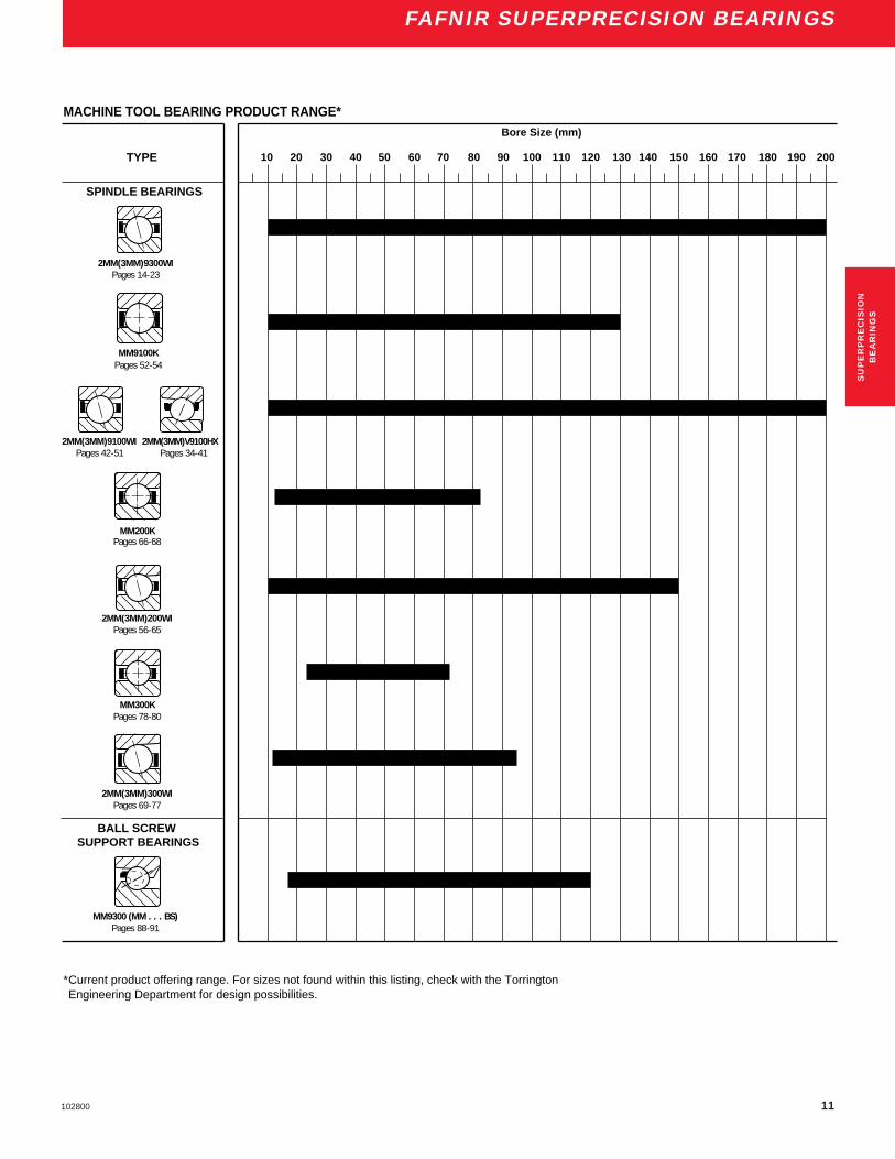
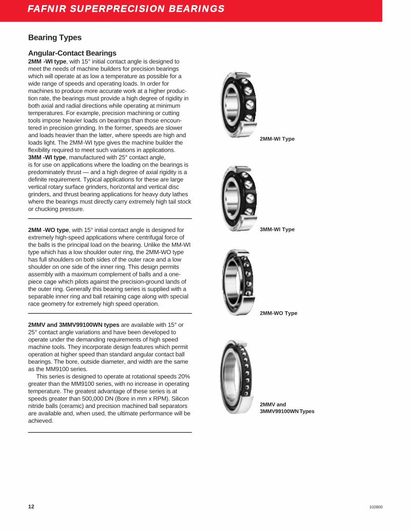
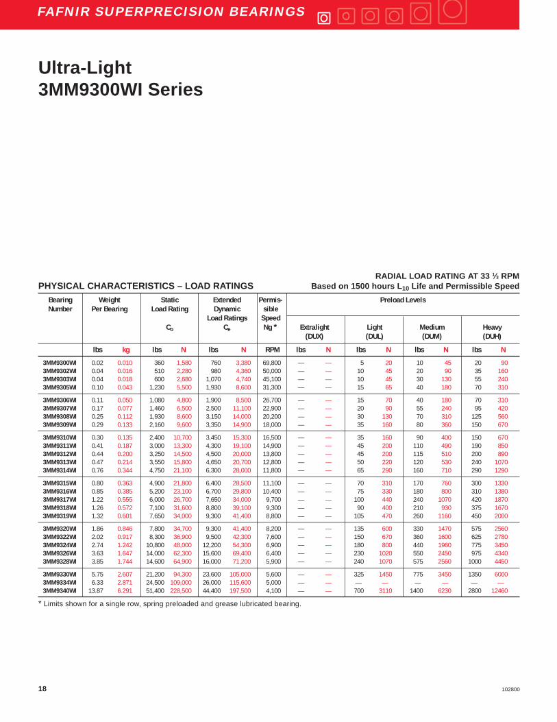
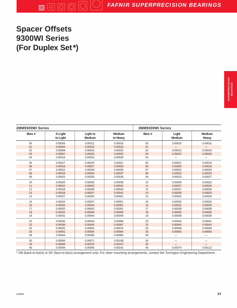
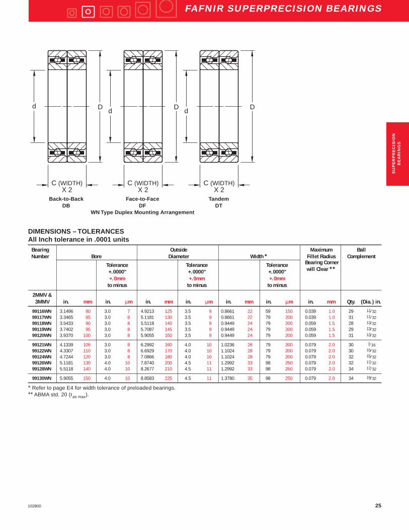
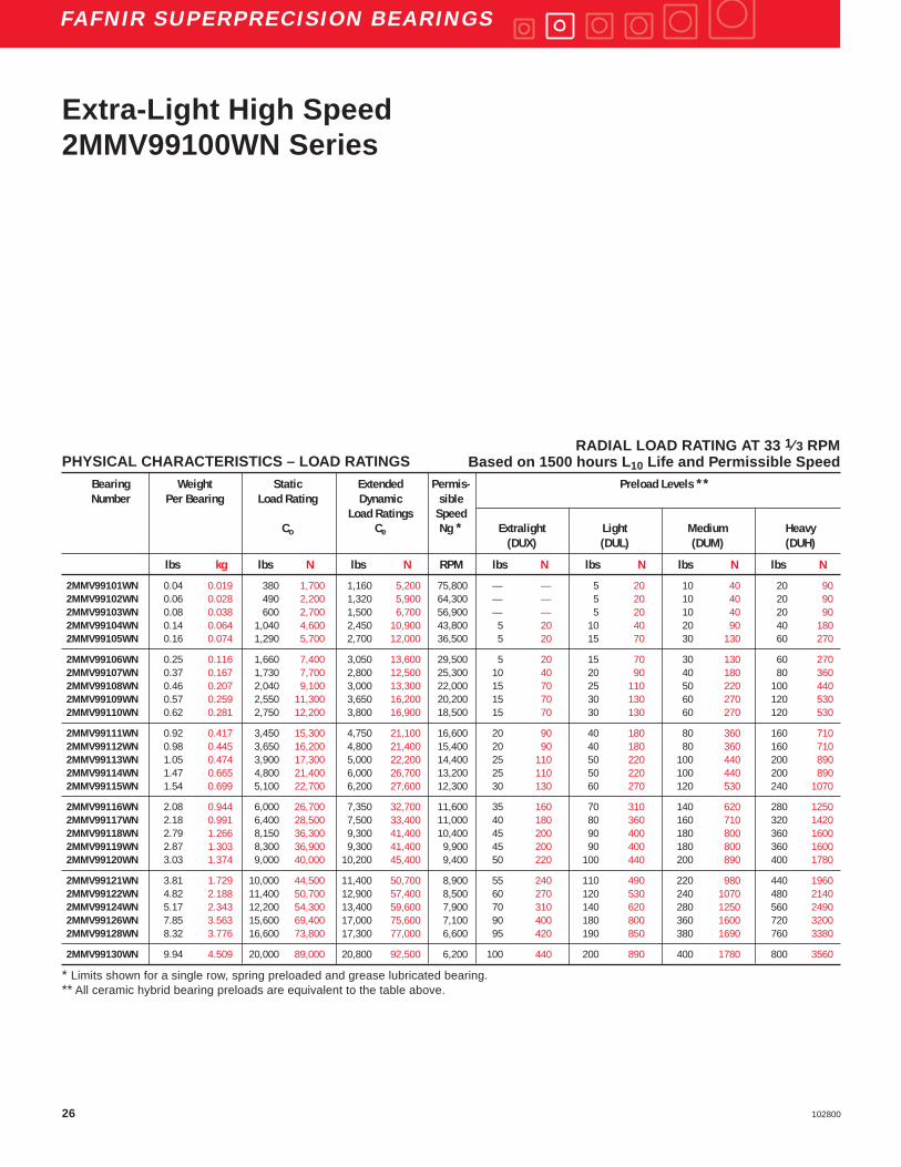
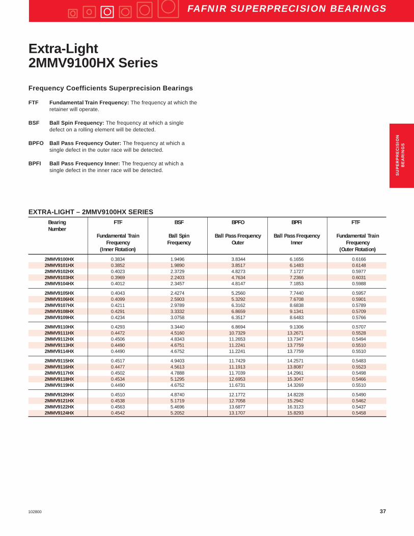
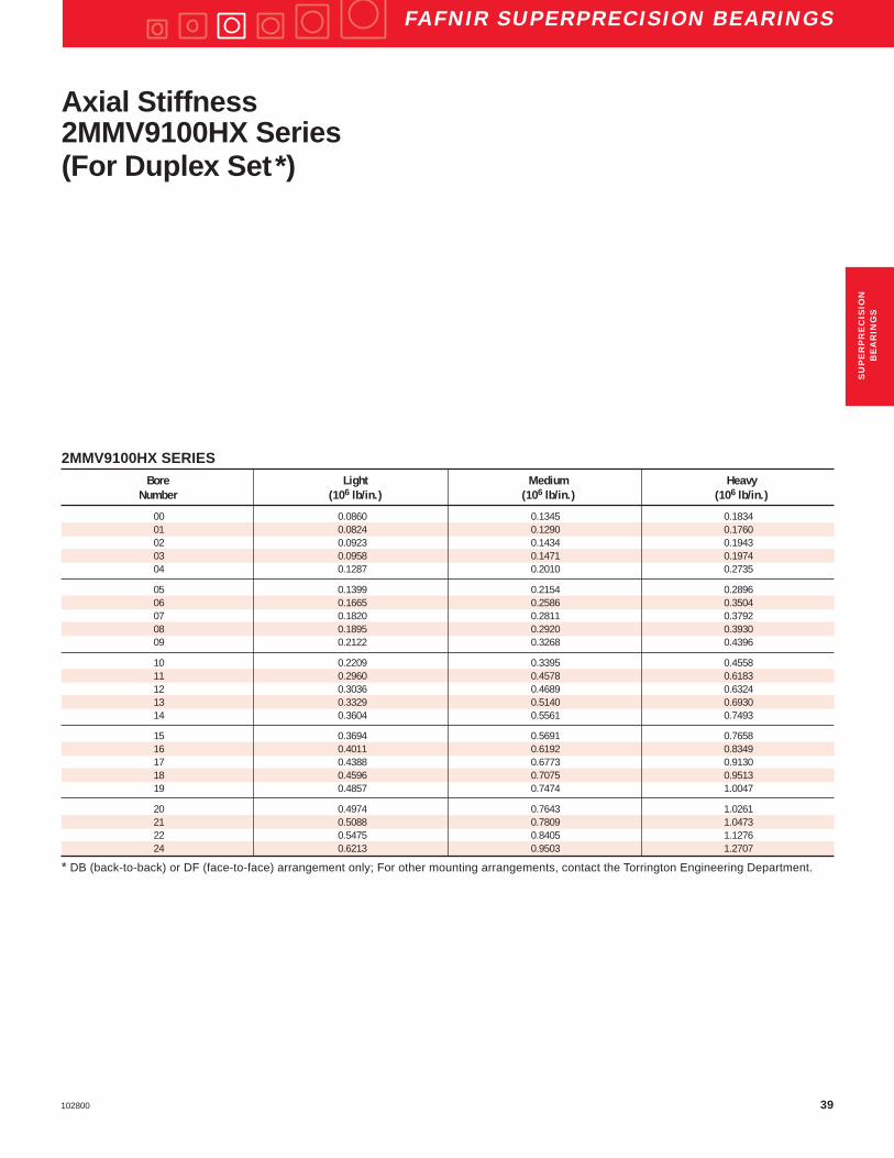
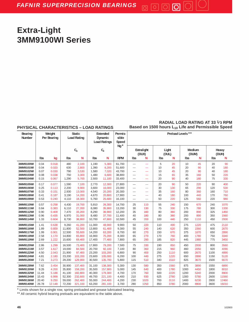
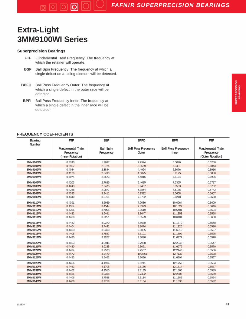
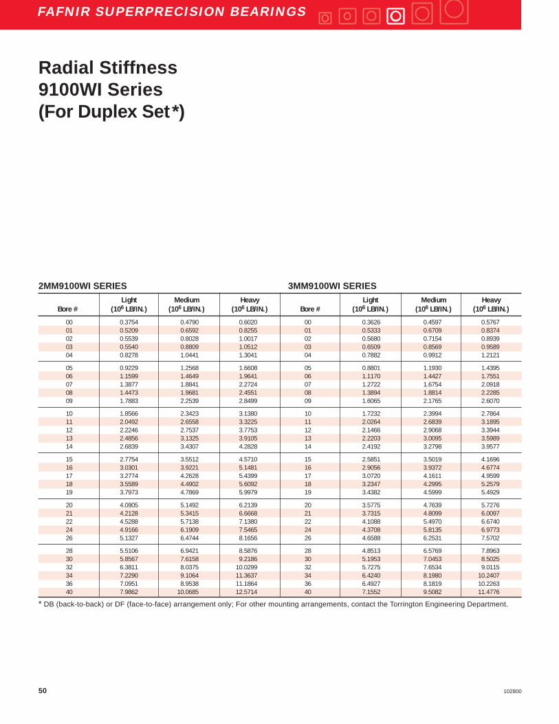
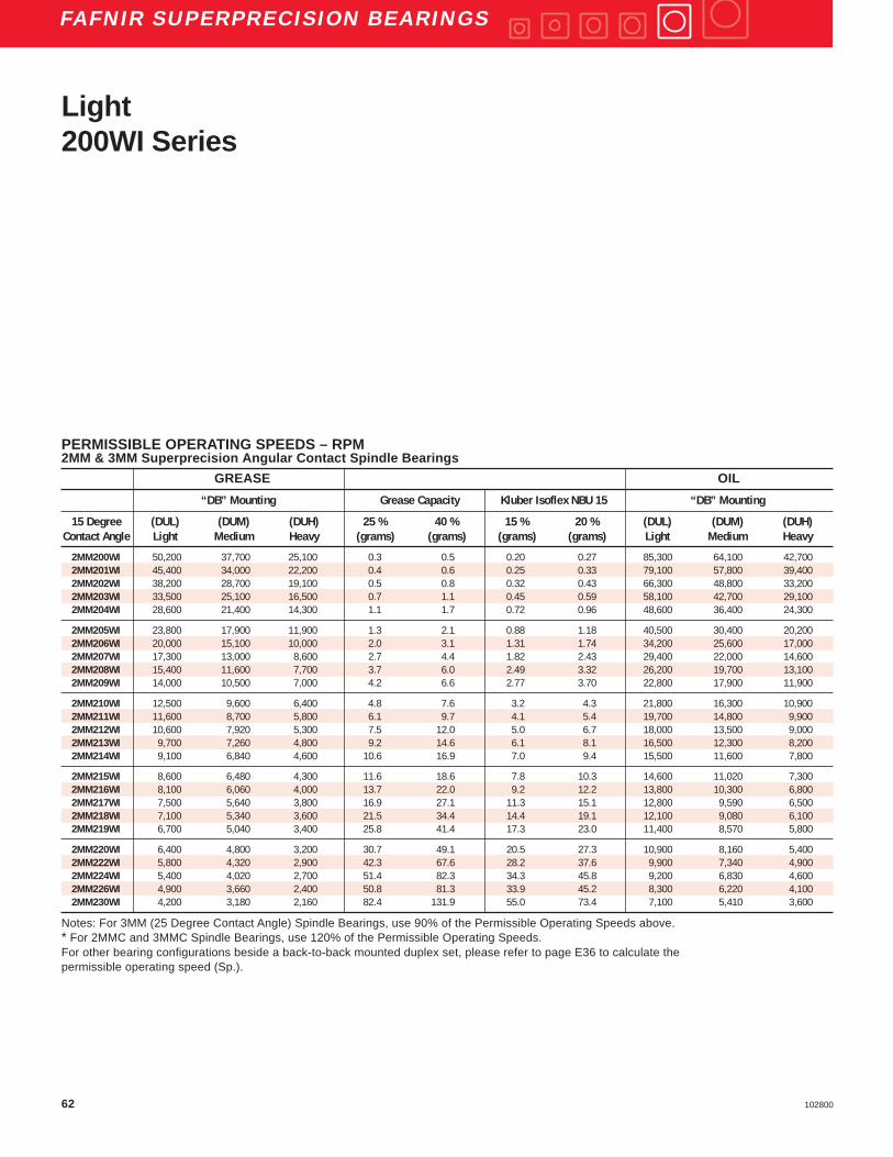
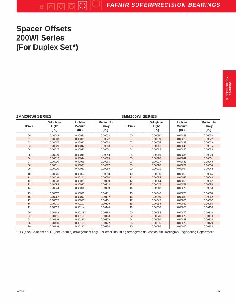
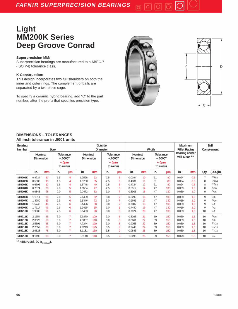
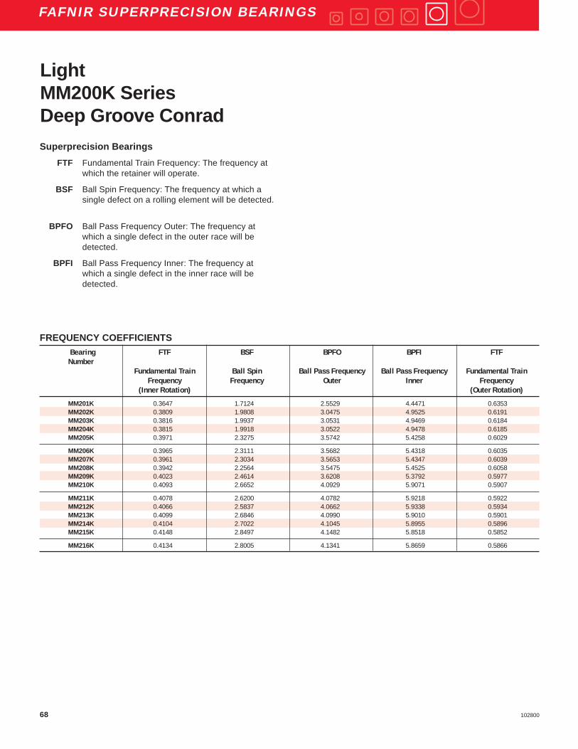
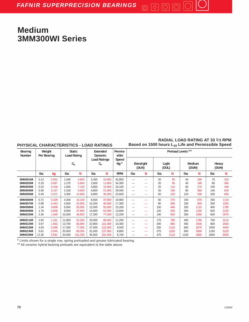
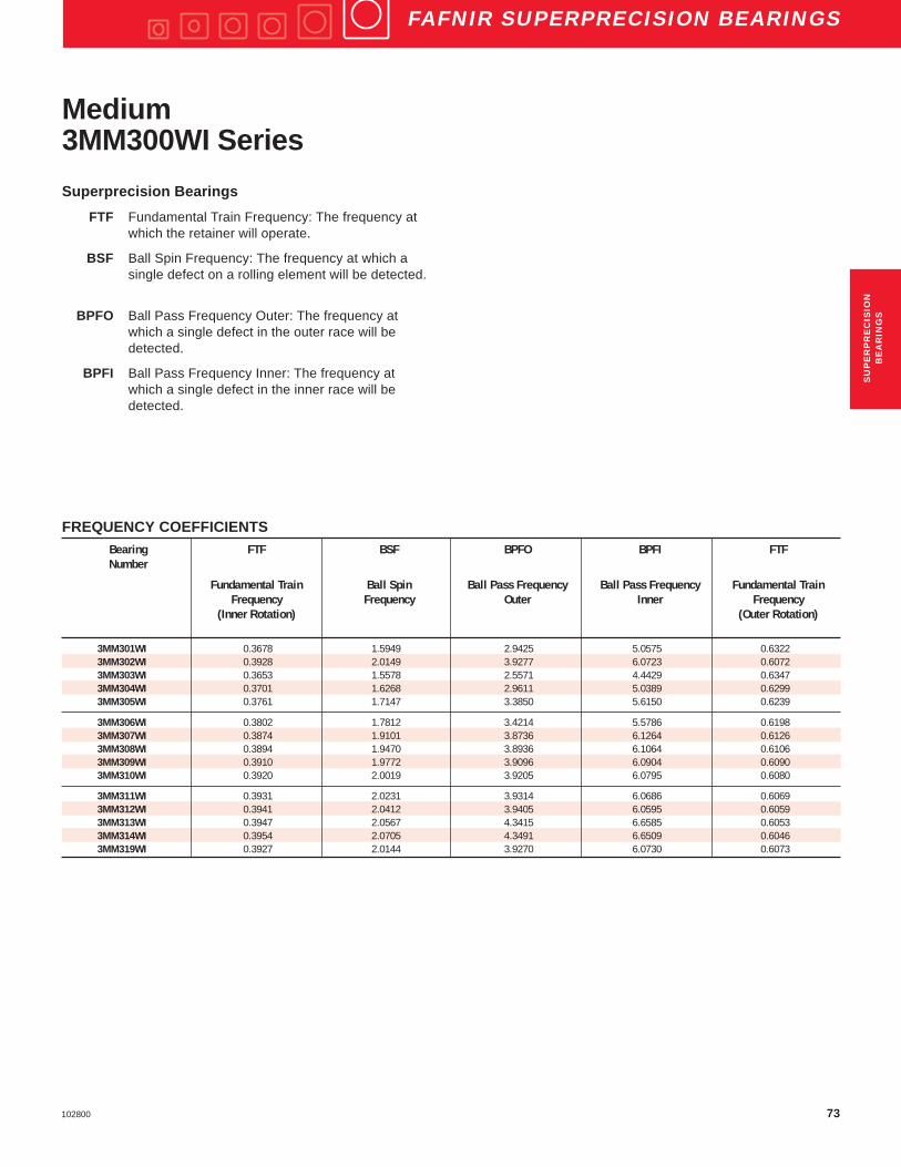
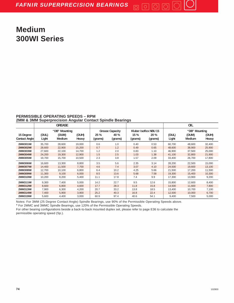
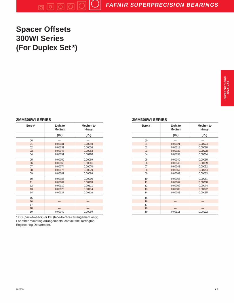
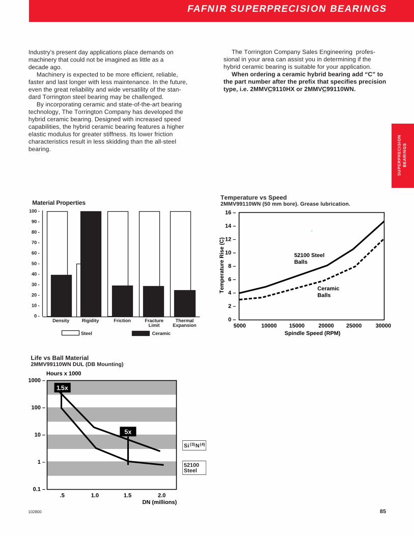
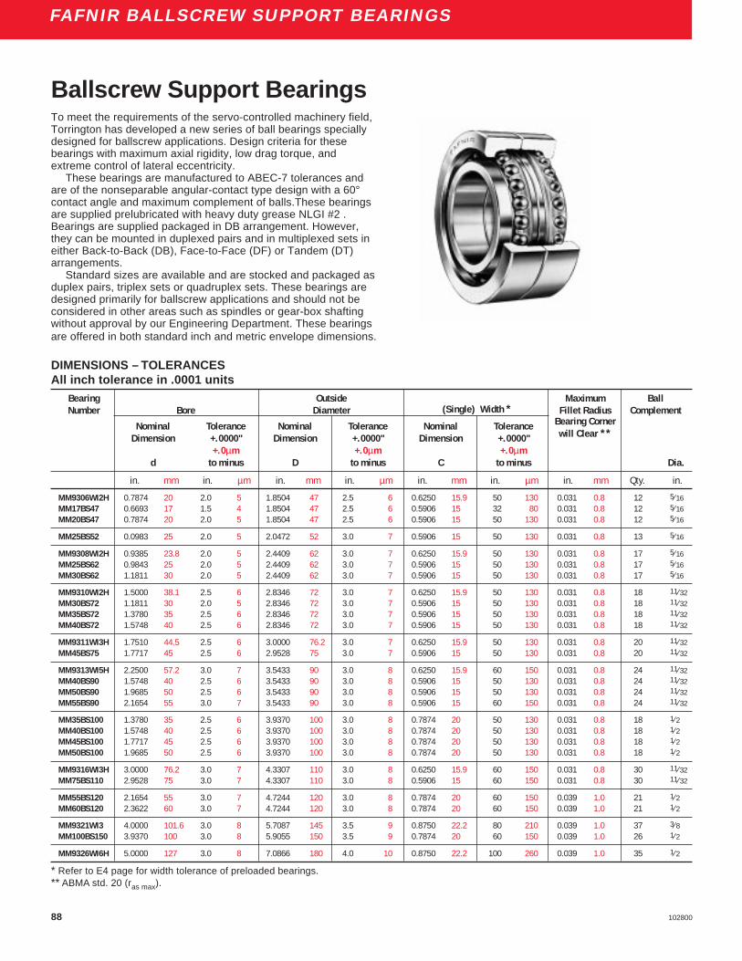
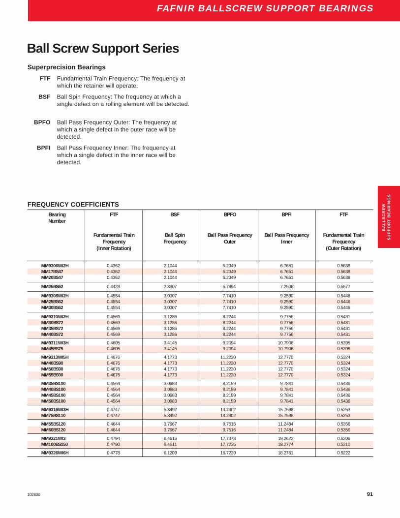
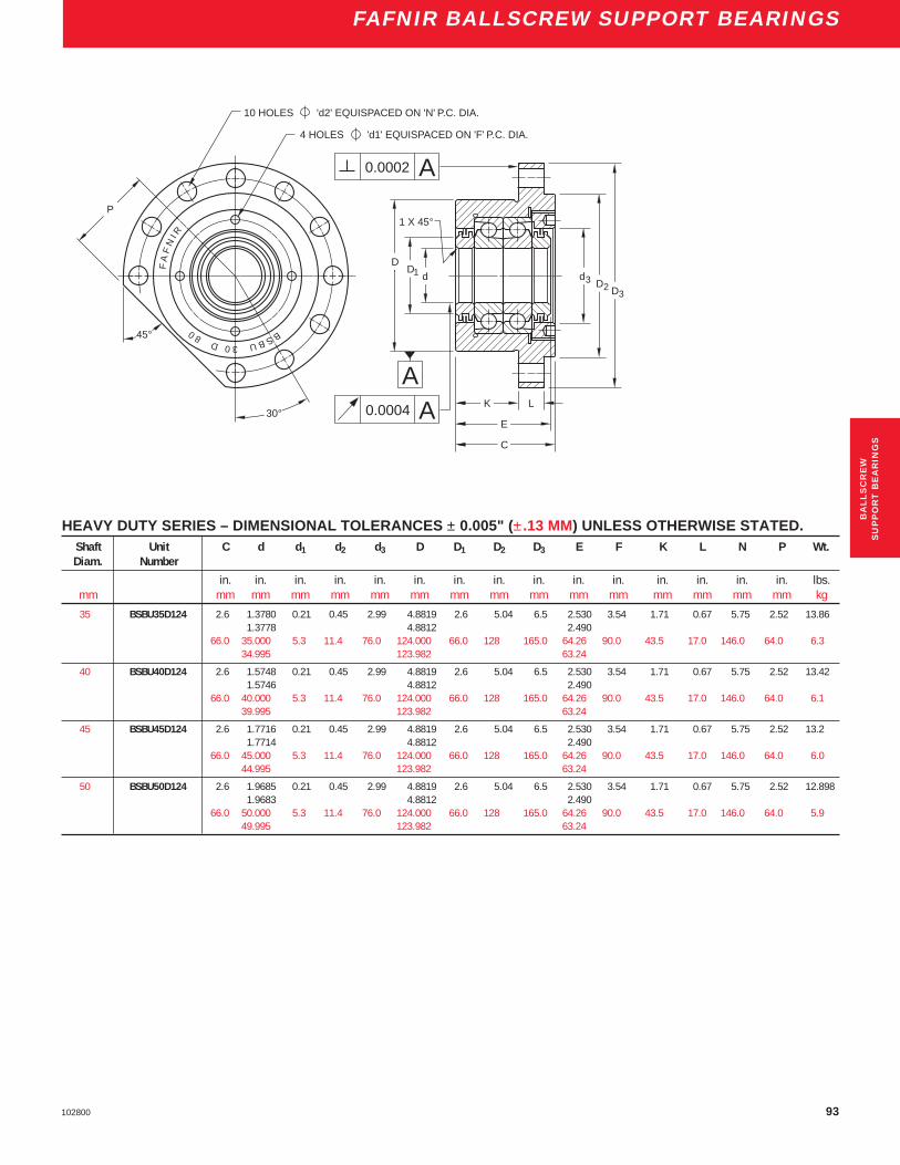
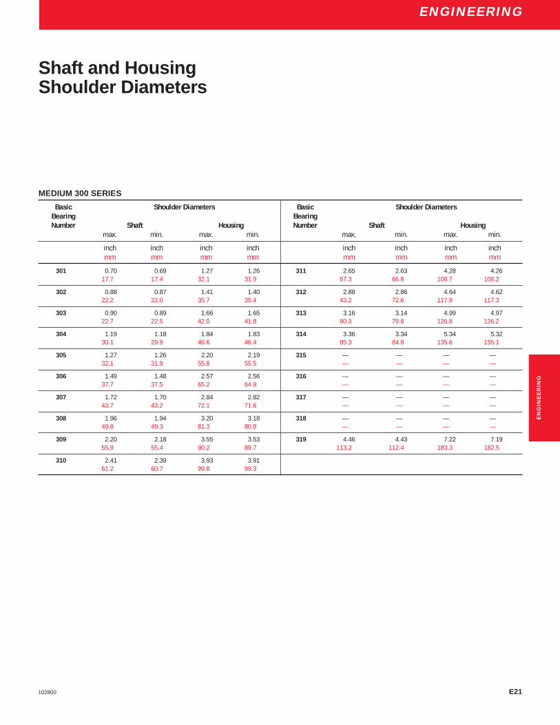
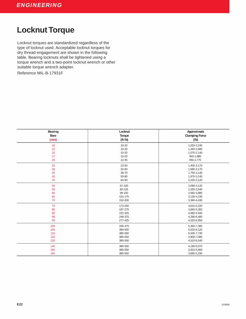
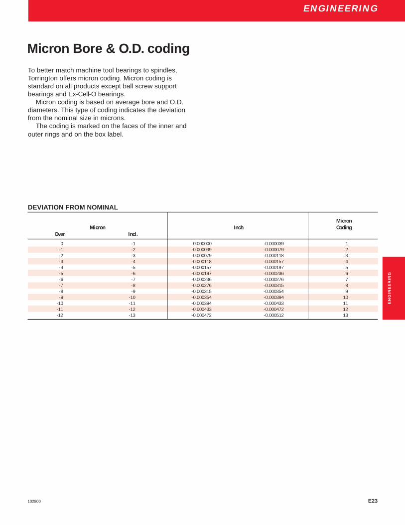
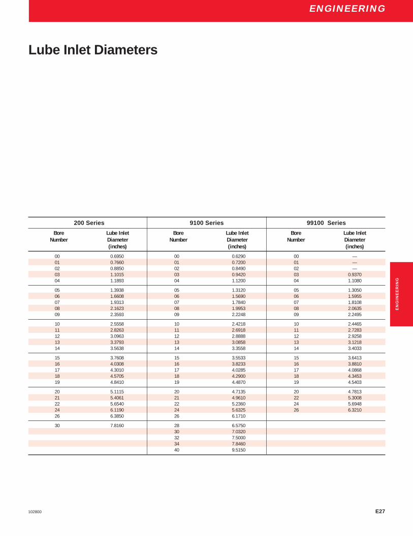
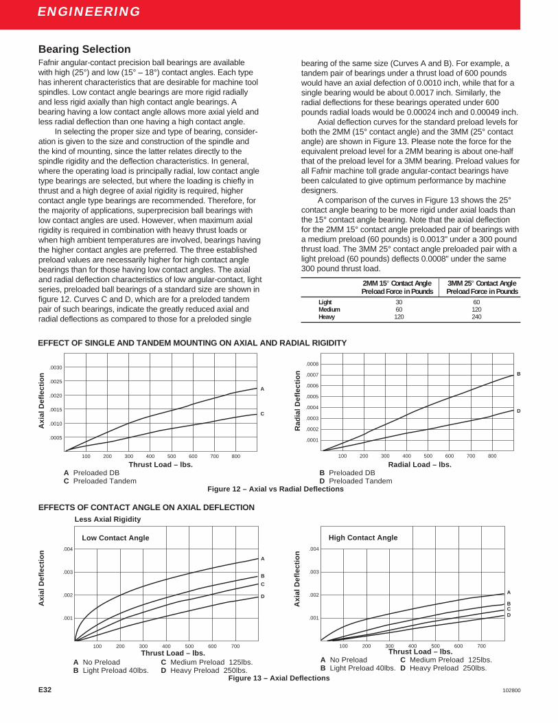
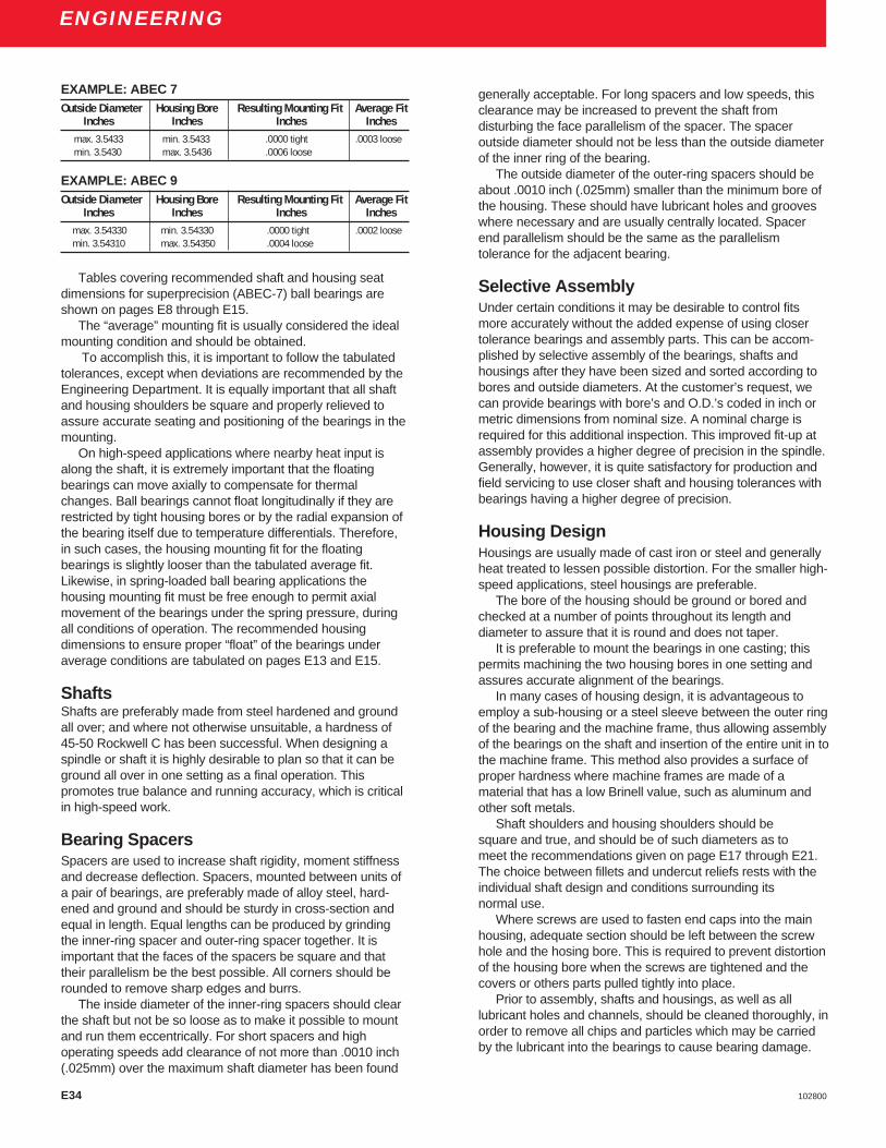
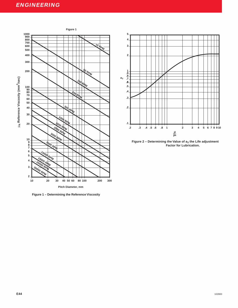
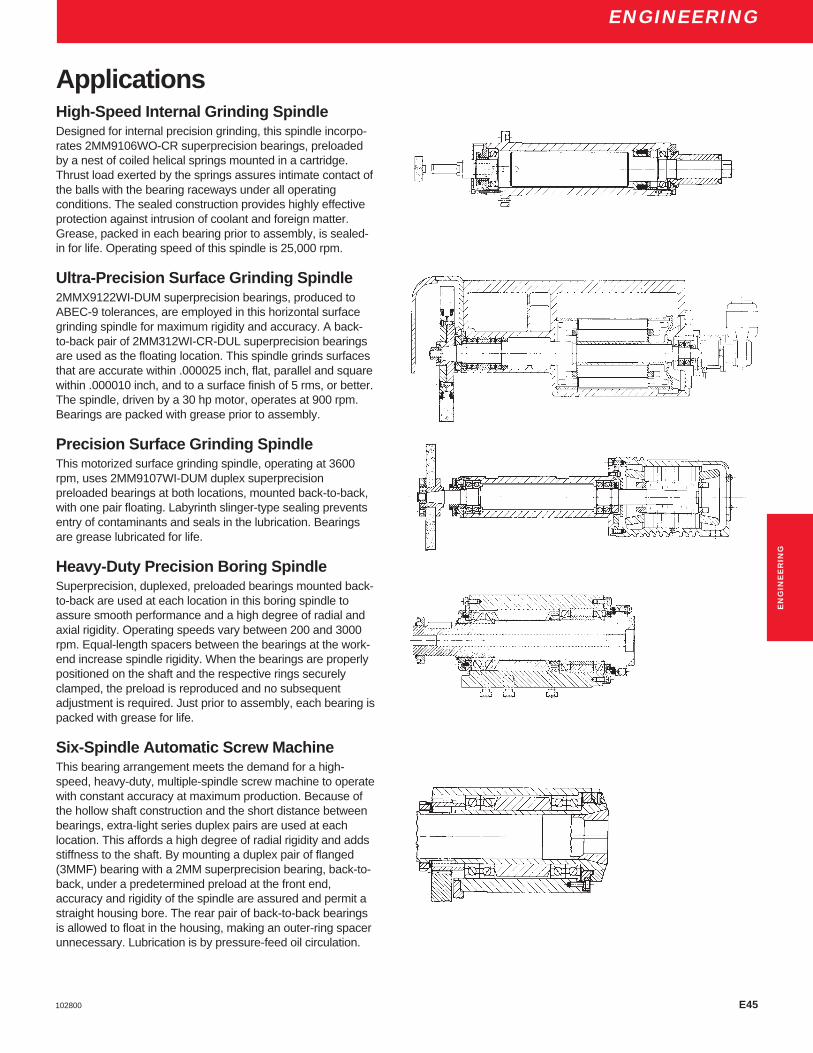
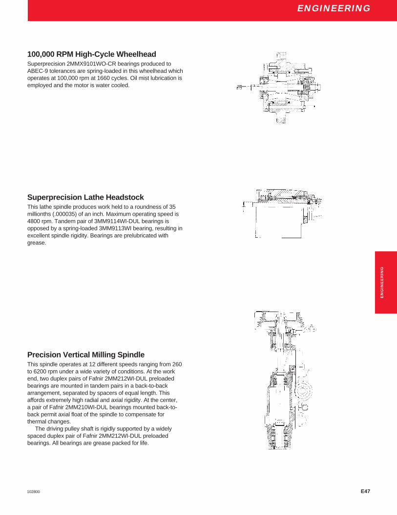
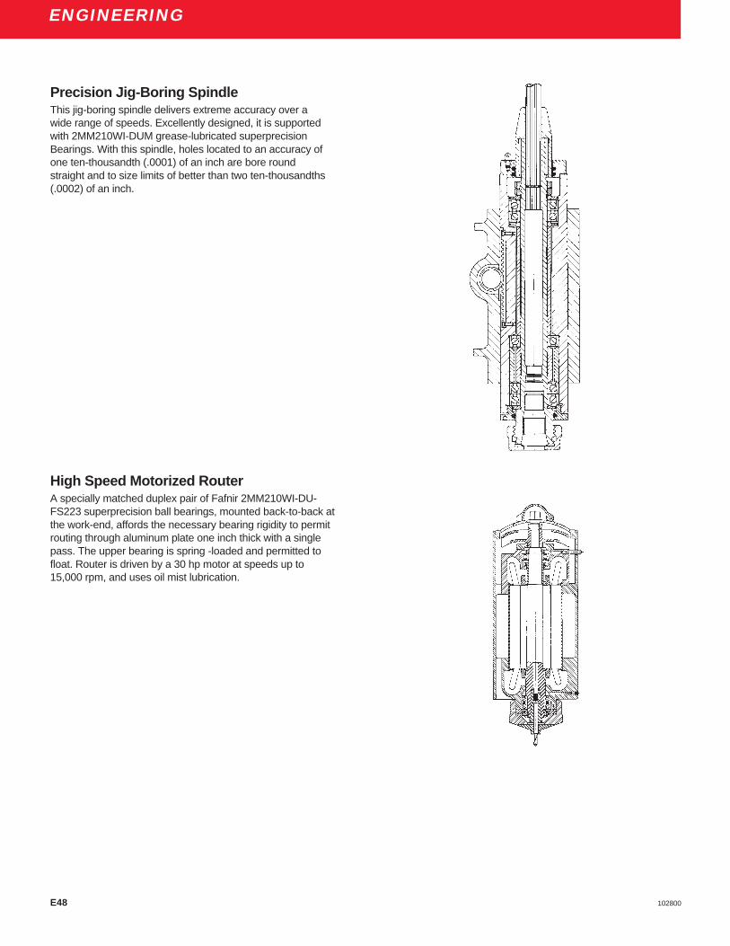
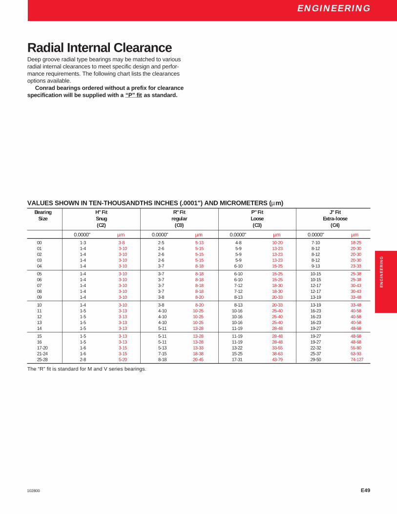
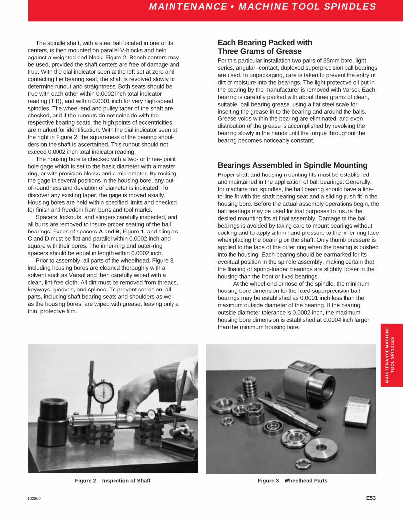
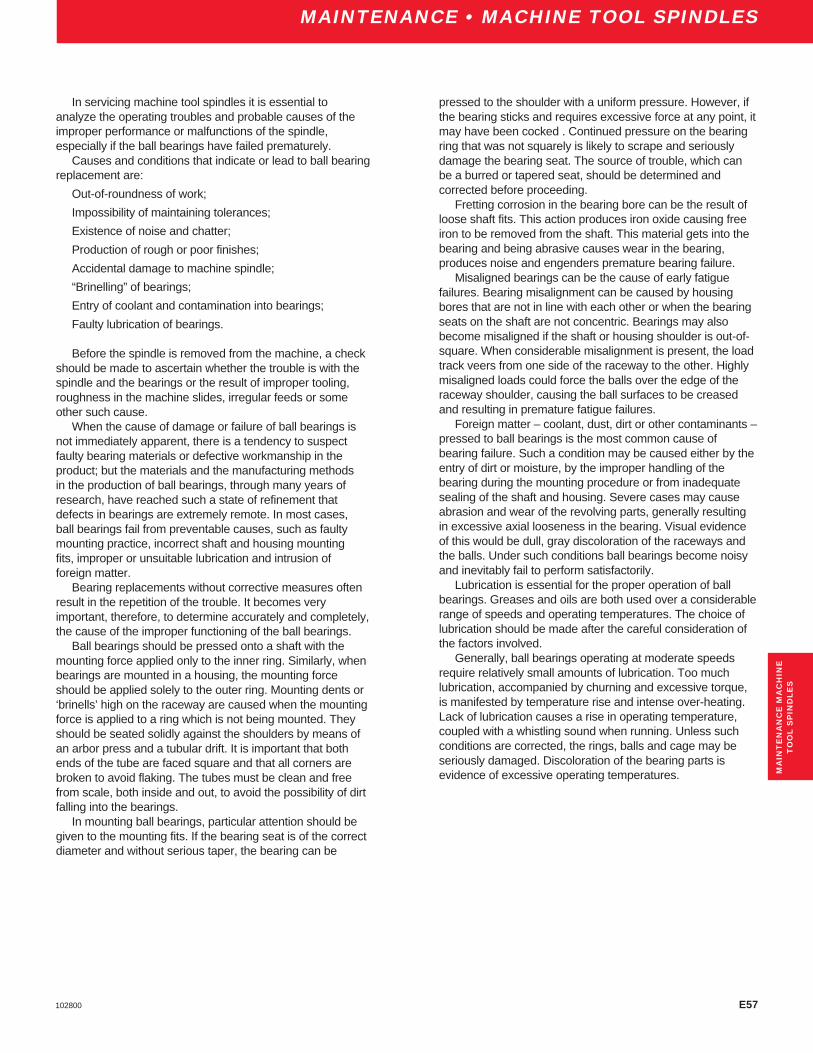
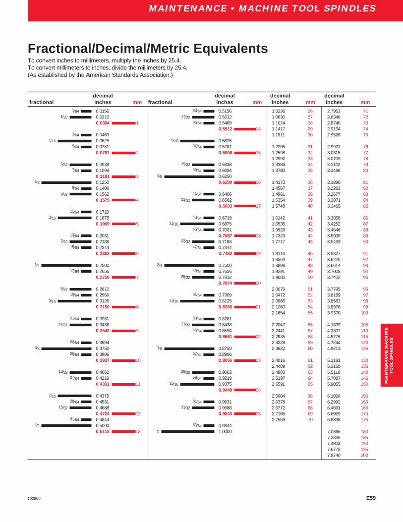
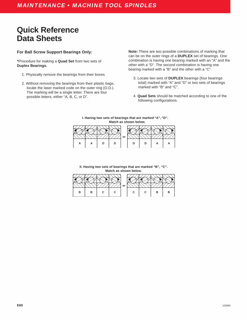
SPEED: (rpm) OSCILLATION ANGLE: (Total Degrees) FREQ.: (opm)

LUBRICATION METHOD: BRAND:

TEMP: AMBIENT (°F) HOUSING (°F) BEARING (°F) LUBRICANT (°F)

SHAFT FIT/SIZE: HOUSING FIT/SIZE:

INSTALLATION METHOD: HYDRAULIC MECHANICAL THERMAL OTHER

REMOVAL METHOD: HYDRAULIC MECHANICAL THERMAL OTHER

OPERATING EQUIPMENT CONDITION

INITIAL INDICATION OF BEARING DAMAGE: VIBRATION NOISE HEAT OTHER

SHAFT CONDITION:

HOUSING CONDITION:

LUBRICANT CONDITION:

INNER RING CONDITION:

OUTER RING CONDITION:

CAGE CONDITION:

ROLLING ELEMENTS CONDITION:

GENERAL COMMENTS:

MA

INT

EN

AN

CE

MA

CH

INE

TO

OL

SP

IND

LE

S

FAFNIR ENGINEERING DAMAGED BEARING ANALYSIS SHEET

E64 102800

ENGINEERINGINDEX

A PageABEC Tolerances,Introduction . . . . . . . . . . . . . . . . . . . . . . . . . . E3ABEC-7 Description . . . . . . . . . . . . . . . . . . . . . . . . . . . . . . . . . . . 10ABEC-7 Housing Mounting Fits . . . . . . . . . . . . . . . . . . . . . E10-E15ABEC-7 Shaft Mounting Fits . . . . . . . . . . . . . . . . . . . . . . . . E8, E9ABEC-7,-9 Standard Tolerances Inner and Outer Rings . . . E4, E5ABEC-9 Description . . . . . . . . . . . . . . . . . . . . . . . . . . . . . . . . . . . 10ABMA/ISO Symbols – Inner Ring . . . . . . . . . . . . . . . . . . . . . . . E4ABMA/ISO Symbols – Outer Ring . . . . . . . . . . . . . . . . . . . . . . . E5Angular Contact Bearings, Introduction . . . . . . . . . . . . . . . . . . . . 12Applications . . . . . . . . . . . . . . . . . . . . . . . . . . . . . . . . . . . . E45-E48

BBack-To-Back vs Face-To-Face Mounting . . . . . . . . . . . . . . . . E30Ballscrew Support Bearings . . . . . . . . . . . . . . . . . . . . . . . . . 87-100Ballscrew Support Bearings, Introduction . . . . . . . . . . . . . . . . . . 13Ballscrew Support Bearings, Nomenclature Chart . . . . . . . . . . . . 86Ballscrew Support Bearings, Shaft and Housing Shoulder Dimensions . . . . . . . . . . . . . . . . . . . . . . . . . . . . . . . E16Bearing Locknuts . . . . . . . . . . . . . . . . . . . . . . . . . . . . . . . . . . . E35Bearing Selection . . . . . . . . . . . . . . . . . . . . . . . . . . . . . . . . . . E32Bearing Spacers . . . . . . . . . . . . . . . . . . . . . . . . . . . . . . . . . . . E34Bearing and Shaft Assembled with Eccentricities Opposed . . . E54Bearings Assembled in Spindle Mounting . . . . . . . . . . . . . . . . E53

CChecking Spindle Temperature, Vibration, Roughness . . . . . . E56Cleanliness . . . . . . . . . . . . . . . . . . . . . . . . . . . . . . . . . . . E56, E57Conditions of Sale . . . . . . . . . . . . . . . . . . . . . . . . . . . . . . . . . . . . . 5

DDistribution Service Centers . . . . . . . . . . . . . . . . . . . . . . . . . . E66Drip Feed Oil Lubrication . . . . . . . . . . . . . . . . . . . . . . . . . . . . . E38Dynamic Load Rating . . . . . . . . . . . . . . . . . . . . . . . . . . . E41, E42

EEngineering . . . . . . . . . . . . . . . . . . . . . . . . . . . . . . . . . . . . . E1-E49Engineering,Forward . . . . . . . . . . . . . . . . . . . . . . . . . . . . . . . . . E2Engineering Notations . . . . . . . . . . . . . . . . . . . . . . . . . . . . . . . E41Engineering Sales Offices and Distribution Service Centers . . E66Equivalency Tables . . . . . . . . . . . . . . . . . . . . . . . . . . . . . . . . . E59Ex-Cell-O Spindle Bearings . . . . . . . . . . . . . . . . . . . . . . . . . . . . . 79Extended Basic Dynamic Load Rating . . . . . . . . . . . . . . . E41, E42Extra-Light 2MM9100WI, 3MM9100WI Series . . . . . . . . . . . . 42-51Extra-Light 2MMV99100WN, 3MMV99100WN Series . . . . . . 24-33Extra-Light 2MMV9100HX Series . . . . . . . . . . . . . . . . . . . . . 34-41

F PageFafnir Superprecision Bearings . . . . . . . . . . . . . . . . . . . . . . . . . . . 4Fractional, Decimal, Metric Equivalents . . . . . . . . . . . . . . . . . . E59

GGrease Lubrication . . . . . . . . . . . . . . . . . . . . . . . . . . . . . . . . . E37Grease Shelf Life Policy . . . . . . . . . . . . . . . . . . . . . . . . . . . . . . . . 6

HHeat Generation . . . . . . . . . . . . . . . . . . . . . . . . . . . . . . . . . . . E35Housing Design . . . . . . . . . . . . . . . . . . . . . . . . . . . . . . . . . . . . E34Housing Mounting Fits, ABEC-7 . . . . . . . . . . . . . . . . . . . . E10-E15Housing Mounting Fits, Floating Bearings . . . . . . . . . . . . . E13-E15Housing Seals . . . . . . . . . . . . . . . . . . . . . . . . . . . . . . . . . . . . . E35Hybrid Ceramic Bearings . . . . . . . . . . . . . . . . . . . . . . . . . . . . 84, 85

IInspection of Parts Before Assembly . . . . . . . . . . . . . . . . . . . . E52Introduction . . . . . . . . . . . . . . . . . . . . . . . . . . . . . . . . . . . . . . . . 4-6

LLiability . . . . . . . . . . . . . . . . . . . . . . . . . . . . . . . . . . . . . . . . . . . . . 5Life Adjustment Factors for Lubrication . . . . . . . . . . . . . . . . . . E43Life Calculations – Life Adjustment Factor . . . . . . . . . . . . . . . . E43Life Calculations – Load Ratings . . . . . . . . . . . . . . . . . . . . E41-E43Light 2MM200WI, 3MM200WI Series . . . . . . . . . . . . . . . . . . 56-65Light MM200K Series . . . . . . . . . . . . . . . . . . . . . . . . . . . . . . 65-68Limiting speed (calculation) . . . . . . . . . . . . . . . . . . . . . . . . . . . E36Load Ratings

Ballscrew Support Series . . . . . . . . . . . . . . . . . . . . . . . . . 89-90Extra-Light MM9100K . . . . . . . . . . . . . . . . . . . . . . . . . . . . . . 53Extra-Light 2MM9100WI, 3MM9100WI Series . . . . . . . . . 44, 46Extra-Light 2MMV99100WN, 3MMV99100WN Series . . . 26, 28Extra-Light 2MM9100HX Series . . . . . . . . . . . . . . . . . . . . . . . 36Light 2MM200WI Series . . . . . . . . . . . . . . . . . . . . . . . . . . . . . 58Light 3MM200WI Series . . . . . . . . . . . . . . . . . . . . . . . . . . . . . 60Light MM200K Series . . . . . . . . . . . . . . . . . . . . . . . . . . . . . . . 67Medium 2MM300WI, 3MM300WI Series . . . . . . . . . . . . . 70, 72Medium MM300K Series . . . . . . . . . . . . . . . . . . . . . . . . . . . . 79Ultra-Light 2MM9300WI Series . . . . . . . . . . . . . . . . . . . . . . . 16Ultra-Light 3MM9300WI Series . . . . . . . . . . . . . . . . . . . . . . . 18Lubrication . . . . . . . . . . . . . . . . . . . . . . . . . . . . . . . . . . . . . E37Lubrication, Types of . . . . . . . . . . . . . . . . . . . . . . . . . . E37-E39

MMM-EX Replacement Bearings . . . . . . . . . . . . . . . . . . . . . . . . . . 82MM-XWO Replacement Bearings . . . . . . . . . . . . . . . . . . . . . . . . 83Machine Tool Product Offering Range . . . . . . . . . . . . . . . . . . . . . 11Maintenance Procedure . . . . . . . . . . . . . . . . . . . . . . . . . . . . . . E52Maintenance Machine Tool Spindles . . . . . . . . . . . . . . . . . E52-E58Maintenance Machine Tools, Forward . . . . . . . . . . . . . . . . . . . E52Medium 2MM300WI, 3MM300WI Series . . . . . . . . . . . . . . . . . . . 69Medium MM300K Series . . . . . . . . . . . . . . . . . . . . . . . . . . . . . . . 78

E65102800

ENGINEERINGINDEX

IND

EX

N PageNomenclature Chart, Ballscrew Support Bearings . . . . . . . . . . . . 86Nomenclature Chart, Superprecision Bearings . . . . . . . . . . . . . . . 8Notations, Life Calculations . . . . . . . . . . . . . . . . . . . . . . . . . . . E41Nuclear Application . . . . . . . . . . . . . . . . . . . . . . . . . . . . . . . . . . . . 5

OOil Bath Lubrication . . . . . . . . . . . . . . . . . . . . . . . . . . . . . . . . . E38Oil Jet Lubrication . . . . . . . . . . . . . . . . . . . . . . . . . . . . . . . . . . E38Oil . . . . . . . . . . . . . . . . . . . . . . . . . . . . . . . . . . . . . . . . . . . . . . E38Oil Mist Lubrication . . . . . . . . . . . . . . . . . . . . . . . . . . . . . . . . . E38

PPreloading . . . . . . . . . . . . . . . . . . . . . . . . . . . . . . . . . . . . . . . . E31Product Offering Range . . . . . . . . . . . . . . . . . . . . . . . . . . . . . . . . 11

RRecommended Shaft and Housing Tolerances . . . . . . . . . . . . E33Reference Viscosity . . . . . . . . . . . . . . . . . . . . . . . . . . . . . . . . . E44Replacement Bearings

Ex-Cell-O Spindles, MM-EX . . . . . . . . . . . . . . . . . . . . . . . . . . 82Ex-Cell-O Spindles, MM-XWO . . . . . . . . . . . . . . . . . . . . . . . . 83

SSafety Recommendations . . . . . . . . . . . . . . . . . . . . . . . . . . . . . . . 5Scraping Locknut to Eliminate Runout . . . . . . . . . . . . . . . . . . . E55Selective Assembly . . . . . . . . . . . . . . . . . . . . . . . . . . . . . . . . . E34Shaft Mounting Fits, ABEC-7 . . . . . . . . . . . . . . . . . . . . . . . . . E8-E9Shaft and Housing Shoulder Diameters . . . . . . . . . . . . . . . E17-E21Shaft and Housing Tolerances . . . . . . . . . . . . . . . . . . . . . . . . . E33Shafts, Materials . . . . . . . . . . . . . . . . . . . . . . . . . . . . . . . . . . . E34Special Requirements . . . . . . . . . . . . . . . . . . . . . . . . . . . . . . . E35Spring-Loaded Mountings . . . . . . . . . . . . . . . . . . . . . . . . . . . . E31Standard Preloads in Pounds . . . . . . . . . . . . . . . . . . . . . . . . . E31Standard Tolerances, Inner Ring, ABEC-7,-9 . . . . . . . . . . . . . . E4Standard Tolerances, Outer Ring, ABEC-7,-9 . . . . . . . . . . . . . . E5Standard and Heavy Duty Bearings

BSBU D Series . . . . . . . . . . . . . . . . . . . . . . . . . . . . . . . . 92, 93BSBU Q Series . . . . . . . . . . . . . . . . . . . . . . . . . . . . . . . . 94, 95BSPB D Series . . . . . . . . . . . . . . . . . . . . . . . . . . . . . . . . . 96, 97BSPB Q Series . . . . . . . . . . . . . . . . . . . . . . . . . . . . . . . . 98, 99

Static Radial Load Capacity . . . . . . . . . . . . . . . . . . . . . . . . . . . E40Storage and Grease Shelf Life . . . . . . . . . . . . . . . . . . . . . . . . . . . . 6Successful Applications . . . . . . . . . . . . . . . . . . . . . . . . . . . . . . E35Super High Precision MMV (HG), Introduction . . . . . . . . . . . . . . . 10Superprecision Bearing Products . . . . . . . . . . . . . . . . . . . . . . . 8-83Superprecision MM (ABEC-7), Introduction . . . . . . . . . . . . . . . . . 10Superprecision, Nomenclature Chart . . . . . . . . . . . . . . . . . . . . . . . 8

T PageThe Torrington Commitment . . . . . . . . . . . . . . . . . . . . . . . . . . . . . 4The Torrington Company, Introduction . . . . . . . . . . . . . . . . . . . . . 4Tolerances . . . . . . . . . . . . . . . . . . . . . . . . . . . . . . . . . . . . . . . . . E3Typical Mountings, Duplex Bearings . . . . . . . . . . . . . . . . . . . . E29

UUltra-Light Series 2MM9300WI and 3MM9300WI . . . . . . . . . 14-19Ultrapecision MMX (ABEC-9), Introduction . . . . . . . . . . . . . . . . . 10Using This Catalog . . . . . . . . . . . . . . . . . . . . . . . . . . . . . . . . . . . . 4

WWarranty . . . . . . . . . . . . . . . . . . . . . . . . . . . . . . . . . . . . . . . . . . . . 5Width Tolerances . . . . . . . . . . . . . . . . . . . . . . . . . . . . . . . . . . . . E4

E66 102800

ENGINEERINGSALES OFFICES

Engineering Sales Offices

Distribution Service Centers

MIDWEST DSC(Chicago)

1400 Opus PlaceDowners Grove, IL 60515-5701Tel: (800) 372-4669Fax: (630) 241-0890

WEST COAST DSC(Reno)

245 E. Liberty StreetReno, NV 89501-2220Tel: (800) 372-4669Fax: (775) 334-4510

SOUTHEAST DSC(Atlanta)

3200 Highlands ParkwaySmyrna, GA 30082-5192Tel: (800) 372-4669Fax: (720) 438-8801

SOUTHWEST DSC(Dallas)

4545 Fuller DriveIrving, TX 75038-6530Tel: (800) 372-4669Fax: (972) 717-4499

NORTHEAST DSC(Philadelphia)

210 Farm LaneDoylestown, PA 18901Tel: (800) 372-4669Fax: (215) 489-9188

NORTH AMERICAALABAMA

1855 Data DriveBirmingham, AL 35244-1237Tel: (205) 987-4966Fax: (205) 987-4933

CALIFORNIA12750 Center Court DriveCerritos, CA 90703Tel: (562) 865-4343Fax: (562) 865-4361

COLORADOAcademy Park Commons7114 West Jefferson Ave.Lakewood, CO 80235-2309Tel: (303) 986-0133Fax: (303) 989-8485

CONNECTICUT197 Scott Swamp Rd.Farmington, CT 06032Tel: (860) 677-1911Fax: (860) 677-2024

INDIANA10585 North Meridian St.Indianapolis, IN 46290-1066Tel: (317) 846-3411Fax: (317) 846-4434

KANSASCloverleaf Bldg. #26901 West 63rd St.Overland Park, KS 66202-4005Tel: (913) 362-4640Fax: (913) 362-1233

MICHIGAN44670 Ann Arbor RoadPlymouth, MI 48170-3908Tel: (734) 455-7300Fax: (734) 455-8154

38701 Seven Mile RoadLivonia, MI 48152-1058Tel: (734) 462-4870Fax: (734) 462-1934

MINNESOTA7901 Xerxes Ave. So.Bloomington, MN 55431-1200Tel: (612) 887-2155Fax: (612) 887-2163

NEW YORK349 W. Commercial St.E. Rochester, NY 14445-2404Tel: (716) 381-3643Fax: (716) 381-1909

FLORIDA3751 Maguire Blvd.Orlando, FL 32803Tel: (407) 896-1444Fax: (407) 896-4007

GEORGIA3200 Highlands Pkwy.Smyrna, GA 30082-5193Tel: (770) 438-7313Fax: (770) 438-7718

ILLINOIS1701 52nd AvenueMoline, IL 61265-6377Tel: (309) 762-5254Fax: (309) 762-7975

1400 Opus PlaceDowners Grove,IL 60515-5701Tel: (630) 663-0290Fax: (630) 663-0296

401 N.E. Jefferson StreetPeoria, IL 61603-3725Tel: (309) 676-9560Fax: (309) 676-9938

NORTH CAROLINAEnglish Oaks Bldg.8848 Red Oak Blvd.Charlotte, NC 28217-5518Tel: (704) 525-7710Fax: (704) 525-9289

OHIO9039 Springboro PikeMiamisburg, OH 45342-4418Tel: (937) 847-1691Fax: (937) 847-8275

24651 Center Ridge RoadWestlake, OH 44145-5628Tel: (440) 899-2200Fax: (440) 899-2209

PENNSYLVANIA210 Farm LaneDoylestown, PA 18901Tel: (215) 489-9099Fax: (215) 489-9161

Pinebridge Commons1580 McLaughlin Run RoadPittsburgh, PA 15241Tel: (412) 220-1134Fax: (412) 220-1139

TEXAS9802 FM 1960 BypassHumble, TX 77338Tel: (281) 319-6212Fax: (281) 319-5414

LATIN AMERICATo obtain the name of nearestoffice or distributor, pleasecontact:

The Torrington Company730 N.W. 107th Ave.Miami, Florida 33166Tel: (305) 559-0500Fax: (305) 222-0877

EUROPETo obtain the name of nearestoffice or distributor, pleasecontact:

Torrington France8 Rue Henri BecquerelOdyssee 2000F-92508 Rueil MalmaisonCEDEXParis, FranceTel: (33) (1) 47 16 90 00Fax: (33) (1) 47 51 29 09TLX: 631150 TOR FAF

ASIA – PACIFICTo obtain the name of nearestoffice or distributor, pleasecontact:

The Torrington Company42 Benoi Rd.Singapore 629903Tel: (65) 860-6845Fax: (65) 860-6845

TEXAS (cont.)4545 Fuller DriveIrving, TX 75038-6530Tel: (972) 717-4567Fax: (972) 717-4448

WASHINGTONOne Lake Bellevue Bldg.Bellevue, WA 98005-2417Tel: (425) 455-4466Fax: (425) 455-8304

WISCONSINThe Rosewood Bldg.250 Bishop’s WayBrookfield, WI 53005-6265Tel: (262) 784-4844Fax: (262) 784-8903

CANADA (Sales Off./DSC)4246 97th StreetEdmonton, AlbertaCanada T6E 5Z9Tel: (780) 433-9590Fax: (780) 433-9823

6700 Cote de LiesseVille St. Laurent, QuebecCanada H4T 2B5Tel: (514) 340-2990Fax: (514) 340-9314

5598 McAdam RoadMississauga, OntarioCanada L4Z 1P1Tel: (905) 890-2033Fax: (905) 890-0086

INTERNATIONALEuropean Customer Service(ECS)

Torrington Nadellager GmbHWerkstrasse 5D-33790Halle (Westfalen), GermanyTel: (49) 2451-971-450

To obtain the nameof nearest sales officeplease contact:

Tel: (800) 854-0175


Recommended