Supplement to the Installation - and Operating Instructions After Directive 2014/34/EU Roots Vacuum Pumps Puma WP 0250...1000 D/ WP 2000 D Panda WV 0250-2000 C ATEX outside version II 3/2G(o) IIB/IIC T3/T4 X ATEX inside version II 2G(i) IIB T3 X Ateliers Busch S.A. Zone industrielle 2906 Chevenez Switzerland 0870544541/ 160425 / Original instructions / Modifications reserved
Transcript
Supplement to the Installation- and Operating Instructions
After Directive 2014/34/EU
Roots Vacuum Pumps
Puma WP 0250...1000 D/ WP 2000 DPanda WV 0250-2000 C
ATEX outside version II 3/2G(o) IIB/IIC T3/T4 X
ATEX inside version II 2G(i) IIB T3 X
Ateliers Busch S.A.Zone industrielle2906 Chevenez
Switzerland0870544541/ 160425 / Original instructions / Modifications reserved
This supplement contains additional Installation and Maintenance pres-criptions for the pumps Roots Puma WP 0250 D, WP 0500 D2,WP 0700 D,WP 1000 D2, WP 2000 D and Panda WV 0250 C,WV 0500 C, WV 1000 C, WV 1500 C, WV 2000 C in accordance withthe directive 2014/34/EU (ATEX); see nameplate.
Imperatively consider the prescriptions of the Installation and Opera-ting Instructions for the Roots vacuum pumps Puma WP 0250-2000 Dand Panda WV 0250-2000 C.
Prior to handling the vacuum system, these operating instructionsshall be read and understood. If anything remains to be clarifiedplease contact your Busch representative!
Keep these operating instructions and, if applicable, other pertinentoperating instructions available on site.
SafetyApplicationAccording to the equipment, this vacuum pump is adapted for the suc-tion of explosive gases and dusts (category 2 = Zone 1, Zone 22 insideand category 2, Zone 1, Zone 21 outside). The vacuum pump is provi-ded with one of the following explosion protection markings:
1 Equipment in accordance with Directive 2014/34/EU
2 II Equipment group, not for mining applications
3
2 Category 2, for use in Zone 1
3 Category 3, for use in Zone 2
G Explosive atmosphere of gases
(o) “outside”= The outside of the pump (environment)is protected against explosions
(i/o)“inside/ outside”= The inside and the outside of thepump (environment) are protected against explo-sions
4 IIBouIIC Explosion group
5 T3orT4 Temperature class
6 X Special conditions for safe use
If the vacuum pump has received an exterior certification, it can be pla-ced in rooms corresponding to Zone 1 or 2. The term outside (o) refersto the area of the pump which is in contact with the environment. Theterm inside (i) refers to the area of the pump which is in contact withthe process gases.This vacuum pump can only be used if the materials of construction,particularly the temperature sensor at the exhaust, are resistant to che-mical and mechanical attacks (e.g. corrosion) during operation; this isto ensure the explosion protection.
The vacuum pump should not be used for the handling of explosive at-mospheres, which can self-destruct or are chemically unstable.
The authorized ambient operating temperature is situated between-20°C and +40°C and is influenced by the type of oil that is used (see"Oil"-> Installation and Maintenance Instructions standard version).
Intended useDEFINITION: In these instructions, the “ handling ” of the vacuumpump implies the transport, storage, installation, commissioning, in-fluences on operating conditions, maintenance, troubleshooting andoverhaul of the vacuum pump.
The vacuum pump is intended for industrial use. It may be handled byqualified personnel only.
The need for personal safety regulations depends mainly on the appli-cation the pump will be used in. The end user must provide the opera-tors with the necessary means and must inform his personnel aboutany dangers coming from the processed product.
When installing the pump in hazardous areas, local regulations concer-ning the explosion protection must be observed.
The end user of the vacuum pump must observe the safety regulationsand must train and instruct his personnel accordingly.
The maintenance instructions must be observed.
Before start-up make sure that all safety precautions are observed.
These Installation and Maintenance Instructions as well as the standardRoots pump manual must be read and understood before handling thevacuum pump. If in any doubts, please contact your Busch representa-tive.
DismantlingOpening the pump is only allowed after it has been stopped and noexplosive atmosphere is to be found inside the pump.
The use of the vacuum pumps in explosive areas is only authorized ifthe pump is equipped with the safety instrumentation described inthis manual. The authorization is no longer valid in case of modifica-tion of the system as well as in case of non respect of the necessarymaintenance measures. Maintenance work on the vacuum pump mayonly be carried out by specifically trained and authorized staff.
Roots Version ATEX Safety
0870544541 (En) Page 3
WV 2000 C ATEX
Safety notes
WARNING
The vacuum pump with the certification Ex II 2G (i/o) IIB T3 (i)/T4(o) or Ex II 2G(i) IIB T3(i) can only draw explosive gases or va-pours when it is equipped with an active bypass (see page 6) orwhen an exterior by-pass is installed in the periphery of the va-cuum pump (see operational diagram of the external by-pass onpage 5)
CAUTION
Vacuum pumps with interior certification can only be started up
when the suction pressure P1 is <100hPa.
WARNING
Before starting the vacuum pump, make sure of the correct direc-tion of rotation.
WARNING
Operation in the wrong direction of rotation can destroy the va-cuum pump within a short period of time.
Danger of explosion!
CAUTION
During operation the surface temperature of the pump can reachtemperatures of 70°C.
Danger of burns!
WARNING
When using a barrier gas in the cylinder endplates, imperativelymake sure that the connection is completely tight and that the bar-rier gas is not explosive.
Danger of explosion!
Safety notes Roots Version ATEX
Page 4 0870544541 (En)
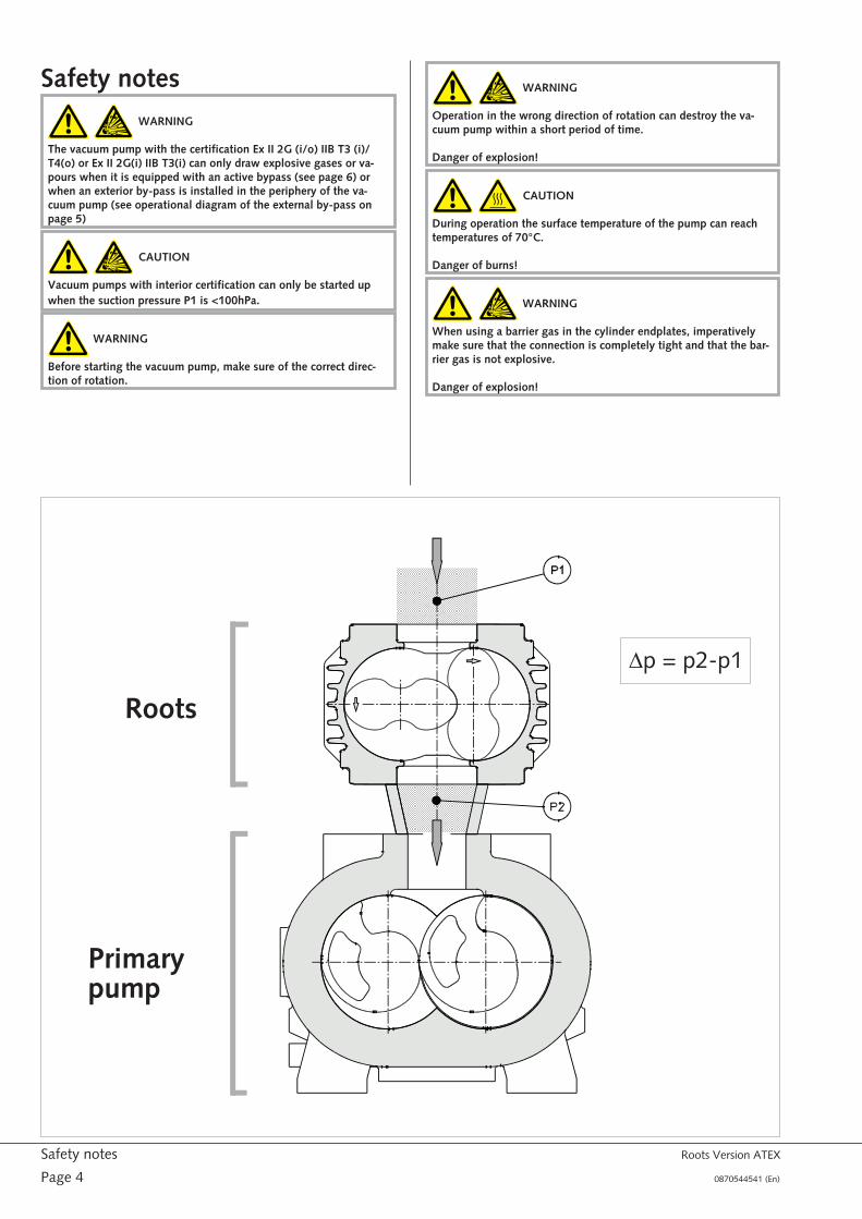
Roots
Primarypump
Dp = p2-p1
Limits of useMaximum pressure differenceDp º Pressure difference between outlet (p2) and inlet (p1) of thepump.
Pump Dp max (hPa)
WV 0250 C 53
WV 0500 C 53
WV 1000 C 43
WV 1500 C 43
WV 2000 C 43
WP 0250 D 80
WP 0500 D2 50
WP 0700 D 50
WP 1000 D2 50
WP 2000 D 50
Motor speedThe maximum motor speed as specified on the motor nameplate(max.50 or 60Hz) must not be exceeded.
Pump controlThe vacuum pump has to be stopped immediately if one of the moni-toring elements exceeds the set value.
WARNING
Obligatory minimal surveillance for vacuum pumps certified
II 2G(i/o) IIB T... / II 2G(o) IIB T... / II 2G(i) IIB T3:
- Temperature at the exhaust TSA+/ 0101- Temperature of the magnetic coupling bell SA+/ 0102 (option)
The customer must operate the pump in accordance with explosionprotection regulations.
The temperature of the exhaust gases has to be monitored with a tem-perature sensor (PT100 or thermocouple) has to be fitted as shown inthe following drawing: The value "x" must be between 30 and 50mm.
Monitoring the magnetic couplingWhen a magnetic coupling with ceramic bell has been fitted, the moni-toring of the surface temperature of the bell by a temperature sensor isobligatory.
See "Supplement to the Installation and Maintenance Manual forRoots pumps with magnetic coupling"
Connecting flange (elbow+hose nipple+PT100)
d=Lw 60
DN 0100 DN 0160
PT 100 without transmitter 0947 539 135 0947 539 138
PT 100 with transmitter 0947 539 136 0947 539 139
Plug 0947 539 137 0947 539 140
d=Lw 90
DN 0100 DN 0160
PT 100 without transmitter 0947 539 141 0947 539 144
PT 100 with transmitter 0947 539 142 0947 539 145
Plug 0947 539 143 0947 539 146
CAUTION
When the temperature sensor sends a warning signal, the vacuumpump has to be stopped
Maximum switch-off temperatures at theexhaust for vacuum pump with certificationEx II 2G(o)
PumpMax. switch-off temperatures
at the exhaust TSA+/0101[°C]*
Temperatureclass (outside)
WV 0250 C 130 T4
WV 0500 C 140 T4
WV 1000 C 180 T4
WV 1500 C 180 T4
WV 2000 C 170 T4
WP 0250 D 130 T4
WP 0500 D 150 T4
WP 0700 D 180 T4
WP 1000 D 215 T3
WP 2000 D 240 T3
* valid temperatures even if the vacuum pump is certified T3 (o)
Maximum switch-off temperatures at theexhaust for vacuum pump with certificationEx II 2G(i/o) or 2G(i) with active bypass
Pump
Max. switch-offtemperatures at theexhaust TSA+/0101
[°C]*
Tempera-ture class(inside)
Tempera-ture class(outside)
WV 0250 C 140 T3 T4
WV 0500 C 150 T3 T4
WV 1000 C 150 T3 T4
WV 1500 C without certification 2G(i/o) with active bypass
WV 2000 C 160 T3 T4
* valid temperatures even if the vacuum pump is certified T3 (o)
Roots Version ATEX Limits of use
0870544541 (En) Page 5
OUT
IN
RTD (=PT100) / TC (Thermoelement)
RTD (=PT100) / TC (Thermocouple)
RTD (=PT100) / TC (Thermocouple)
x
Maximum switch-off temperatures at theexhaust for vacuum pump with certificationEx II 2G(i/o) or 2G(i) with external bypass
Pump
Max. switch-offtemperatures at theexhaust TSA+/0101
[°C]*
Tempera-ture class(inside)
Tempera-ture class(outside)
WV 0250 C 140 T3 T4
WV 0500 C 150 T3 T4
WV 1000 C 150 T3 T4
WV 1500 C 160 T3 T4
WV 2000 C 160 T3 T4
WP 0250 D 140 T3 T4
WP 0500 D 150 T3 T4
WP 0700 D 150 T3 T4
WP 1000 D 160 T3 T4
WP 2000 D 160 T3 T4
* valid temperatures even if the vacuum pump is certified T3 (o)
Roots Panda or Puma withexternal bypass (option)For certification Ex II 2G(i/o) IIB/C T3(i)/T4(o)or II 2G(i) IIB T3Functional diagram with external bypass
Roots Panda with activebypassFor certification Ex II 2G(i/o) IIB/C T3(i)/T4(o)or II 2G(i) IIB T3
DescriptionAs long as the absolute pressure inside the pump is above 100hPa,there is a risk of explosion. When the pressure inside the pump dropsbelow 100hPa, conditions for the formation of gas mixtures, whosedensity presents a risk of explosion and overheating, do no longer pre-vail and thus the pump can be used in its temperature class defined byATEX Directive 2014/34/EU.
The PANDA ROOTS blowers are fitted with a bypass valve as standardequipment, which is integrated in the cylinder. Its role is to open and toshortcut the pump’s process chamber by connecting the suction inletwith the discharge, as soon as the differential pressure between the in-let and outlet exceeds a value of 50hPa. This is an overload security de-vice, as a differential pressure above 50hPa leads to increased powerconsumption and therefore to an increase of the gas temperature andpossible overheating of the pump.
In order to use this integrated bypass valve to allow gases to flowwhen the absolute pressure is above 100hPa, the bypass is opened me-chanically. At an inlet pressure between atmospheric pressure and theabsolute pressure of 100hPa, the bypass valve is kept open and theprimary pump draws gases through the bypass. At the same time therotors of the ROOTS pump are immobilised. When the pressure dropsbelow 100hPa the ROOTS pump starts and the bypass valve takes upits original position and function.
If during operation the inlet pressure of the pump rises above 100hPathe bypass valve opens again with the help of a pneumatic piston andthe pump is stopped in order to prevent a risk of explosion.
In order to ensure good operation and monitoring of the active bypassvalve, the following components are provided:
l 1.Double activated pneumatic piston
l 2.The bypass body moves freely on the pneumatic piston rod whenin the “open” position
l 3.Pressure sensor, fitted in front of the ROOTS pump in the enduser’s installation. The pressure sensor’s impulse activates the ope-ning and closing of the pneumatic piston
l 4.Proximity sensor, which detects the “open” position of the by-pass valve
l 5.Nozzles for speed limitation of the pneumatic piston
Speed monitoring of pneumatic pistonThe upward and downward movement of the pneumatic piston is limi-ted by two nozzles fitted at the entries of the piston (pos.5).
Roots Panda or Puma with external bypass (option) Roots Version ATEX
Page 6 0870544541 (En)
0102
TSA+
0101
TSA+
PC
Option
WV
Option: obligatory and only formagnetic coupling
p < 100hPa abs.
Operating pressure of the pneumaticpistonThe supply pressure should be between 2 and 6 bar.
CAUTION
From an operating pressure of 100 hPa onwards at the inlet of theRoots pump, the bypass must be opened with the pneumaticpiston all the time.
Pressure >100hPaStationary rotorsPneumatic piston in high positionBypass open
Pressure <100hPaRotors in rotationPneumatic piston in low positionBypass free in low position
Pressure <100hPaRotors in rotationPneumatic piston in low position
Bypass free in high position to limit the Dp
Roots Version ATEX Roots Panda with active bypass
0870544541 (En) Page 7
YV
P1 £ 100 hPa Bypass closed
YV
P1 > 100 hPa Bypass open
Functional diagram with active bypass
Roots Panda with active bypass Roots Version ATEX
Page 8 0870544541 (En)
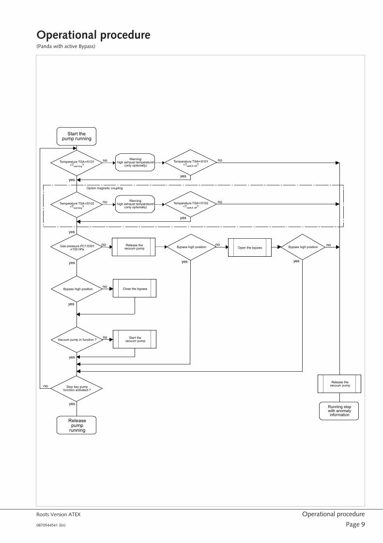
Operational procedure(Panda with active Bypass)
Roots Version ATEX Operational procedure
0870544541 (En) Page 9
Start thepump running
Releasepump
running
Running stopwith anomalyinformation
Stop key pumpfunction activated ?
Vacuum pump in function ?Start the
vacuum pump
Release thevacuum pump
no
no
no
no
yes
yes
yes
yes
yes
Bypass high position
Warning:high exhaust temperature!
(only optionally)
yes
Open the bypassno
Temperature TSA+/0101<Twarning?
Temperature TSA+/0101<Tswitch off?
no
yes
Gas pressure PC /0301<100 hPa
no
Release thevacuum pump
Close the bypassno
yes
Bypass high position
Bypass high position
no
yes
Warning:high exhaust temperature!
(only optionally)
yes
Temperature TSA+/0102<Twarning?
Temperature TSA+/0102<Tswitch off?
no
Option magnetic coupling
Electrical connection/ Controlsl Make sure that the requirements according to EMC-Directive
2014/30/EU as well as the current EN-standards, electrical and oc-cupational safety directives and the local or national regulationsrespectively, are complied with (this is the responsibility of the de-signer of the machinery into which the vacuum pump is to be in-corporated; see also the corresponding comments in theEC-Declaration of Conformity).
l Make sure that the power supply is compatible with the data onthe nameplate of the drive motor
l Make sure that an overload protection according to EN 60204-1 isprovided for the drive motor
l Connect the pump and the motor up to the equipotential :Explosion-proof drive motors must be protected against overloadin accordance with VDE 0113. The installation manual of the mo-tor delivered with the pump must also be read and observed.Under certain pressure conditions it is possible that the nominal
current of the motor is exceeded if, at the same time, the pumpreaches the maximum counter pressure. Please contact your localBusch agency for further information.
l Make sure that the drive motor of the vacuum pump will not beaffected by electric or electromagnetic disturbances from themains; if necessary seek advice from the Busch service.
l Operation of the pump in the wrong direction of rotation can se-verely damage the pump. In order to change the direction of rota-tion, switch around any two of the three electrical phases.
In case of mobile installation:
u Provide the electrical cables with grommets to retrieve anystrain on the cables
Maintenance
WARNING
The vacuum pump must be used with original components only.
Operation of the vacuum pump with other non-original compo-nents is not permitted.
REMARKS:The maintenance intervals depend mainly on individual ope-ration conditions. The following values are limit values which must notbe exceeded.The operation under difficult conditions will shorten the maintenanceintervals.It is essential to follow the instructions given in the Operating Instruc-tions of the standard pumps for the maintenance of standard parts. Allcleaning jobs, particularly of painted parts, have to be done with adamp cloth in order to avoid electrostatic charge and spark discharge.
Weekly:
u The vacuum pump should be checked for any unusual noisesand vibrations. Observe also the maintenance and service ins-tructions advised by the motor manufacturer.
u Check the cooling water system (WP 2000 D2).
Every 4000 operating hours:
u Check the electric installation for correct operation and da-mage. This also includes the vacuum pump control, the tem-perature sensor (PT100) at the exhaust and the equipotentialthe motor and the pump have to be connected up to.The head of the PT100 must not be twisted as this could da-mage the measuring wires inside.
Every 20000 operating hours:
l General overhaul of the vacuum pump (Busch Service)
u Replace the bearings (overhaul kit)
u Check the shaft seals
u Check the piston rings
Electrical connection/ Controls Roots Version ATEX
Page 10 0870544541 (En)
CouplingManufacturer: KTR KupplungstechnikType: Rotex 24/ 38 with ATEX certification
Protection
II 2G c IIC T4
Rotex size Value E
24 18
38 24
Components
Component Quantity Designation
1 2 Hub
2 1 Spider
3 2 Setscrew DIN 916
Hub assembly
WARNING
Before assembling or servicing the Rotex coupling which is fittedto the pump, the manufacturer’s Operating and MaintenanceInstructions must be read and understood.
CAUTION
During assembly please make sure that the distance value E is keptin order to ensure that the spider remains axially free during opera-tion.
Disregard of the above may cause damage to the coupling.
l Assemble the hubs onto the pump and drive motor sides.
l Move the main parts until value E is attained.
l If the main parts are already assembled, axial movement of thehubs on the shafts will allow for adjustment until value E is attai-ned.
l Fasten the hubs by tightening the setscrews DIN 916 with cup upto a torque of 2 Nm for Rotex 24 an 10 Nm for Rotex 38.
Control intervalsAfter 2000 operating hours for the first time or 3 months at the latest,an inspection for torsional play must be conducted and a visual checkof the flexible spider must be done.With negligible or no wear at the flexible spider after this first inspec-tion, the next inspections can be done at the latest after 4000 opera-ting hours or 12 months respectively, if the same operating parametersprevail.
If considerable wear during the first inspection is detected, meaningthat an exchange of the spider becomes necessary, find out the causein the original manual of the supplier. The original version is availableon Internet site www.ktr.de.The maintenance intervals must then be adapted to the new operatingconditions.The gap between the hub cams and the flexible spider mustbe checked with a feeler gauge.When the maximum limit of wear is reached (X max), the spider mustbe exchanged immediately, regardless of the inspection intervals.
Roots Version ATEX Coupling
0870544541 (En) Page 11
RotexSize
limit of wear (friction) - Xmax (mm)
24 3
38 3
Axial displacementWhen assembling the motor or during maintenance work on the cou-pling, assembly tolerances have to be respected in order to preventaxial displacement.
PumpROTEX
SizeA +/- tolerance
WP 0250 D 38 3 +/- 0,9
WP 0500 D 38 3 +/- 0,9
WP 0700 D 38 3 +/- 0,9
WP 1000 D 38 3 +/- 0,9
WP 2000 D 38 3 +/- 0,9
WV 0250 C 24 2 +/- 0,7
WV 0500 C 24 2 +/- 0,7
WV 1000 C 24 3 +/- 0,9
WV 1500 C 24 3 +/- 0,9
WV 2000 C 24 3 +/- 0,9
Magnetic couplingManufacturer: KTR KupplungstechnikType: Minex 135/ 20 with ceramic bell, with ATEX certificate
Protection class:
II 2G c IIC T4
See "Supplement to the Installation and Maintenance Manual forRoots pumps with magnetic coupling"
Magnetic coupling Roots Version ATEX
Page 12 0870544541 (En)
EU-Declaration of ConformityThis Declaration of Conformity and the CE-mark affixed to the nameplate are valid for the machine within the Busch scope of delivery. This declara-tion of Conformity is issued under the sole responsibility of the manufacturer. When this machine is integrated into a superordinate machinery themanufacturer of the superordinate machinery (this can be the operating company, too) must conduct the conformity assessment process for thesuperordinate machine or plant, issue the Declaration of Conformity for it and affix the CE-mark.
The manufacturer: Ateliers Busch S.A.Zone IndustrielleCH-2906 Chevenez
declare that the machine(s) Puma WP 0250-2000 D and Panda WV 0250-2000 C
with serial number
has (have) been manufactured in accordance with the European Directives:
– “Machinery” 2006/42/EC
– "ATEX Directive" 2014/34/EU for use in potentially explosive areas according to classification written on the machine nameplate
– “Electromagnetic Compatibility” 2014/30/EU
– “RoHS” 2011/65/EU, restriction of the use of certain hazardous substances in electrical and electronic equipment
and following the standards:
Standard Title of the standard
EN ISO 12100:2010 Safety of machinery - Basic concepts, general principles of design
EN ISO 13857:2008 Safety of machinery - Safety distances to prevent hazard zones being reached by the upper and lower limbs
EN 1012-1:2010
EN 1012-2:1996 + A1:2009
Compressors and vacuum pumps - Safety requirements - Part 1 and 2
EN ISO 2151:2008 Acoustics - Noise test code for compressors and vacuum pumps - Engineering method (grade 2)
EN 60204-1:2006 Safety of machinery - Electrical equipment of machines - Part 1: General requirements
EN 61000-6-2:2005 Electromagnetic compatibility (EMC) – Generic standards. Immunity for industrial environments; Part 1 and 3
EN 61000-6-4:2007 +A1:2011
Electromagnetic compatibility (EMC) – Generic standards. Emission standard for industrial environments
EN ISO 13849-1:2015 (1) Safety of machinery - Safety-related parts of control systems - Part 1: General principles for design and 2
EN 13463-1:2009 Non-electrical equipment for potentially explosive atmospheres - Part 1: Basic methodology and requirements
EN 13463-5:2011 Non-electrical equipment for potentially explosive atmospheres - Part 5: Protection by constructional safety "c"
EN 13463-6:2005 Non-electrical equipment for potentially explosive atmospheres - Part 6: Protection by control of ignition source"b"
EN 1127-1:2011 Explosive atmospheres - Explosion prevention and protection - Part 1: Basic concepts and methodology
Person authorised to compile the technical file: Gerd RohwederBusch Dienste GmbHSchauinslandstr. 1DE-79689 Maulburg
Chevenez, 16.03.2016
Christian Hoffmann, General Director
(1) In case control systems are integrated.
Note
Note
Busch – All over the World in Industry www.buschvacuum.comArgentinaBusch Argentina S.R.L.Santo Domingo 3076C1293AGN-Capital FederalBuenos AiresPhone: +54 11 4302 8183Fax: +54 11 4301 0896e-mail: [email protected]
MalaysiaBusch Malaysia Sdn Bhd.4&6, Jalan Taboh 33/22, Seksyen 33Shah Alam Technology Park40400 Shah AlamSelangor Darul EhsanPhone: +60 3 5122 2128Fax +60 3 5122 2108e-mail: [email protected]
MexicoBusch Vacuum Mexico S. de R.L. de C.V.Tlaquepaque 4865, Los AltosMonterrey, Nuevo LeonMexico 64370Phone: +52 81 8311-1385Fax: +52 81 8311-1386e-mail: [email protected]