STEERING SYSTEM SECTION ST CONTENTS PRECAUTIONS ...............................................................2 Supplemental Restraint System (SRS) ″AIR BAG″ and ″SEAT BELT PRE-TENSIONER″ ...............2 Precautions for Steering System.................................2 PREPARATION ...............................................................3 Special Service Tools ..................................................3 POWER STEERING...................................................3 NOISE, VIBRATION AND HARSHNESS (NVH) TROUBLESHOOTING .....................................................5 NVH Troubleshooting Chart.........................................5 ON-VEHICLE SERVICE ..................................................6 Steering System ..........................................................6 Checking Steering Wheel Play ....................................6 Checking Neutral Position on Steering Wheel ............7 PRE-CHECKING........................................................7 CHECKING ...............................................................7 Checking Front Wheel Turning Angle..........................7 Checking and Adjusting Drive Belts ............................7 Checking Fluid Level ...................................................8 Checking Fluid Leakage ..............................................8 Bleeding Hydraulic System..........................................8 Checking Steering Wheel Turning Force ....................9 Checking Hydraulic System.........................................9 STEERING WHEEL AND STEERING COLUMN ......... 11 Components............................................................... 11 Removal and Installation ........................................... 11 STEERING WHEEL ................................................. 11 STEERING COLUMN ...............................................12 Disassembly and Assembly .......................................13 Inspection...................................................................14 TILT MECHANISM ...................................................14 POWER STEERING GEAR (MODEL: D600) ...............15 Description .................................................................15 Removal and Installation ...........................................15 Inspection and Adjustment ........................................16 TURNING TORQUE MEASUREMENT .......................16 POWER STEERING OIL PUMP....................................18 Components...............................................................18 Pre-disassembly Inspection .......................................18 Disassembly...............................................................18 Inspection...................................................................19 Assembly ...................................................................19 STEERING LINKAGE....................................................21 Components...............................................................21 Removal and Installation ...........................................21 Disassembly and Assembly .......................................22 IDLER ARM ASSEMBLY...........................................22 CROSS ROD AND TIE-ROD.....................................22 Inspection...................................................................23 BALL JOINT AND SWIVEL JOINT.............................23 IDLER ARM ASSEMBLY...........................................23 CROSS ROD AND TIE-ROD.....................................23 FIXING LOCATION ..................................................23 SERVICE DATA AND SPECIFICATIONS (SDS) .........24 General Specifications ...............................................24 Steering Wheel ..........................................................24 Steering Column ........................................................24 Power Steering Gear .................................................24 Steering Linkage ........................................................25 GI MA EM LC EC FE CL MT AT TF PD AX SU BR RS BT HA SC EL IDX
Transcript
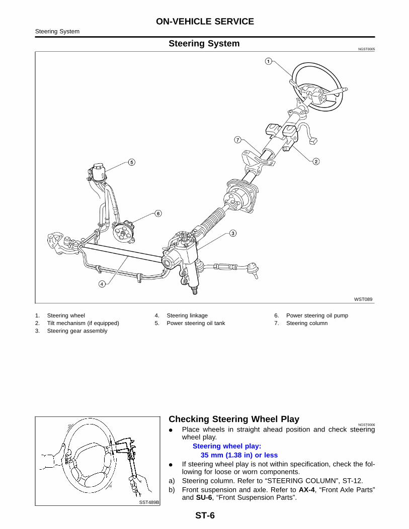
STEERING SYSTEM
SECTIONSTCONTENTS
PRECAUTIONS ...............................................................2Supplemental Restraint System (SRS) ″AIRBAG″ and ″SEAT BELT PRE-TENSIONER″ ...............2Precautions for Steering System.................................2
PREPARATION ...............................................................3Special Service Tools ..................................................3
POWER STEERING...................................................3NOISE, VIBRATION AND HARSHNESS (NVH)TROUBLESHOOTING .....................................................5
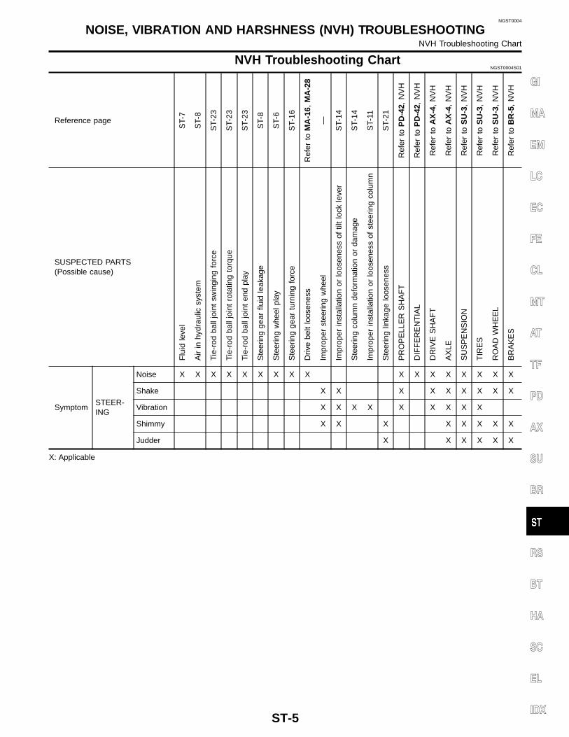
NVH Troubleshooting Chart.........................................5ON-VEHICLE SERVICE ..................................................6
Steering System ..........................................................6Checking Steering Wheel Play....................................6Checking Neutral Position on Steering Wheel ............7
Checking Front Wheel Turning Angle..........................7Checking and Adjusting Drive Belts ............................7Checking Fluid Level ...................................................8Checking Fluid Leakage..............................................8Bleeding Hydraulic System..........................................8Checking Steering Wheel Turning Force ....................9Checking Hydraulic System.........................................9
STEERING WHEEL AND STEERING COLUMN .........11Components...............................................................11Removal and Installation ...........................................11
Description .................................................................15Removal and Installation ...........................................15Inspection and Adjustment ........................................16
STEERING LINKAGE....................................................21Components...............................................................21Removal and Installation ...........................................21Disassembly and Assembly.......................................22
IDLER ARM ASSEMBLY...........................................22CROSS ROD AND TIE-ROD.....................................22
Inspection...................................................................23BALL JOINT AND SWIVEL JOINT.............................23IDLER ARM ASSEMBLY...........................................23CROSS ROD AND TIE-ROD.....................................23FIXING LOCATION ..................................................23
SERVICE DATA AND SPECIFICATIONS (SDS) .........24General Specifications...............................................24Steering Wheel ..........................................................24Steering Column........................................................24Power Steering Gear .................................................24Steering Linkage........................................................25
GI
MA
EM
LC
EC
FE
CL
MT
AT
TF
PD
AX
SU
BR
RS
BT
HA
SC
EL
IDX
Supplemental Restraint System (SRS) “AIRBAG” and “SEAT BELT PRE-TENSIONER”
NGST0001
The Supplemental Restraint System such as “AIR BAG”and “SEAT BELT PRE-TENSIONER” used along witha seat belt, helps to reduce the risk or severity of injury to the driver and front passenger for certain types ofcollision. The Supplemental Restraint System consists of a driver air bag module (located in the center of thesteering wheel), front passenger air bag module (located on the instrument panel on passenger side), seatbelt pre-tensioners, a diagnosis sensor unit, warning lamp, wiring harness and spiral cable.WARNING:� To avoid rendering the SRS inoperative, which could increase the risk of personal injury or death
in the event of a collision which would result in air bag inflation, all maintenance should be per-formed by an authorized NISSAN dealer.
� Improper maintenance, including incorrect removal and installation of the SRS, can lead to per-sonal injury caused by unintentional activation of the system.
� Do not use electrical test equipment on any circuit related to the SRS unless instructed to in thisService Manual. SRS wiring harnesses can be identified by yellow and/or orange harness connec-tors.
Precautions for Steering SystemNGST0002
� Before disassembly, thoroughly clean the outside of the unit.� Disassembly should be done in a clean work area. It is important to prevent the internal parts from
becoming contaminated by dirt or other foreign matter.� For easier and proper assembly, place disassembled parts in order on a parts rack.� Use nylon cloths or paper towels to clean the parts; common shop rags can leave lint that might
interfere with their operation.� Before inspection or reassembly, carefully clean all parts with a general purpose, non-flammable
solvent.� Before assembly, apply a coat of recommended power steering fluid* to hydraulic parts. Petroleum
jelly may be applied to O-rings and seals. Do not use any grease.� Replace all gaskets, seals and O-rings. Avoid damaging O-rings, seals and gaskets during instal-
lation. Perform functional tests whenever designated.*: Genuine NISSAN PSF II or equivalent. Refer to MA-13, “Fluids and Lubricants”.
PRECAUTIONSSupplemental Restraint System (SRS) “AIR BAG” and “SEAT BELT PRE-TENSIONER”
ST-2
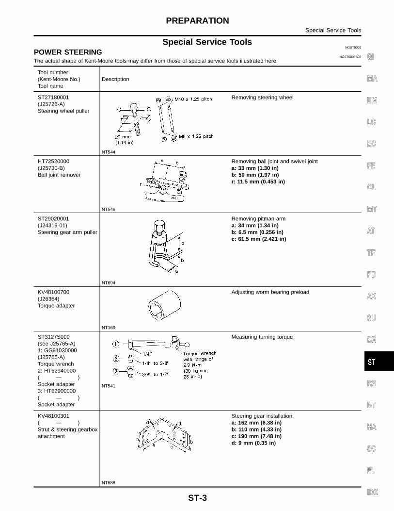
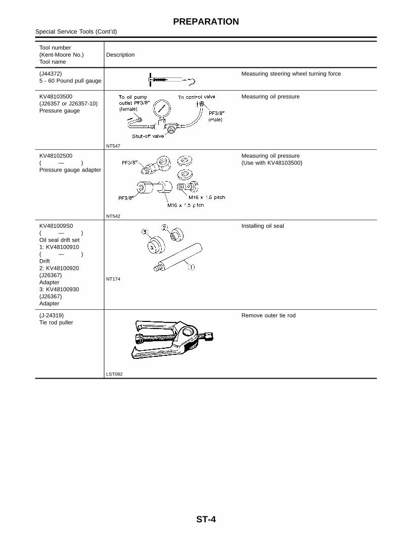
Special Service ToolsNGST0003
POWER STEERINGNGST0003S02
The actual shape of Kent-Moore tools may differ from those of special service tools illustrated here.
Tool number(Kent-Moore No.)Tool name
Description
ST27180001(J25726-A)Steering wheel puller
NT544
Removing steering wheel
HT72520000(J25730-B)Ball joint remover
NT546
Removing ball joint and swivel jointa: 33 mm (1.30 in)b: 50 mm (1.97 in)r: 11.5 mm (0.453 in)
ST29020001(J24319-01)Steering gear arm puller
NT694
Removing pitman arma: 34 mm (1.34 in)b: 6.5 mm (0.256 in)c: 61.5 mm (2.421 in)
� Place wheels in straight ahead position and check steeringwheel play.
Steering wheel play:35 mm (1.38 in) or less
� If steering wheel play is not within specification, check the fol-lowing for loose or worn components.
a) Steering column. Refer to “STEERING COLUMN”, ST-12.b) Front suspension and axle. Refer to AX-4, “Front Axle Parts”
and SU-6, “Front Suspension Parts”.
ON-VEHICLE SERVICESteering System
ST-6
c) Steering gear. Refer to “Description”, ST-15.
SST490BA
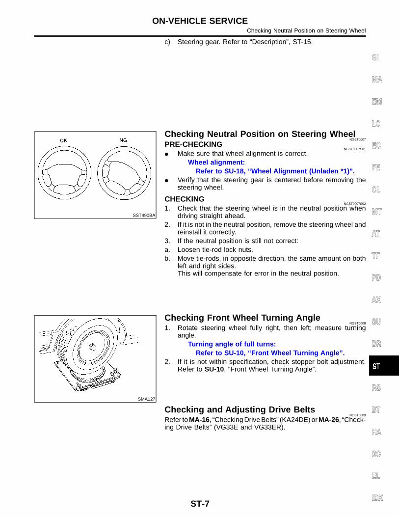
Checking Neutral Position on Steering WheelNGST0007
PRE-CHECKINGNGST0007S01
� Make sure that wheel alignment is correct.Wheel alignment:
Refer to SU-18, “Wheel Alignment (Unladen *1)”.� Verify that the steering gear is centered before removing the
steering wheel.
CHECKINGNGST0007S02
1. Check that the steering wheel is in the neutral position whendriving straight ahead.
2. If it is not in the neutral position, remove the steering wheel andreinstall it correctly.
3. If the neutral position is still not correct:a. Loosen tie-rod lock nuts.b. Move tie-rods, in opposite direction, the same amount on both
left and right sides.This will compensate for error in the neutral position.
SMA127
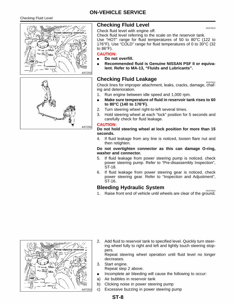
Checking Front Wheel Turning AngleNGST0008
1. Rotate steering wheel fully right, then left; measure turningangle.
Turning angle of full turns:Refer to SU-10, “Front Wheel Turning Angle”.
2. If it is not within specification, check stopper bolt adjustment.Refer to SU-10, “Front Wheel Turning Angle”.
Checking and Adjusting Drive BeltsNGST0009
Refer to MA-16, “Checking Drive Belts” (KA24DE) or MA-26, “Check-ing Drive Belts” (VG33E and VG33ER).
GI
MA
EM
LC
EC
FE
CL
MT
AT
TF
PD
AX
SU
BR
RS
BT
HA
SC
EL
IDX
ON-VEHICLE SERVICEChecking Neutral Position on Steering Wheel
ST-7
AST253
Checking Fluid LevelNGST0010
Check fluid level with engine off.Check fluid level referring to the scale on the reservoir tank.Use “HOT” range for fluid temperatures of 50 to 80°C (122 to176°F). Use “COLD” range for fluid temperatures of 0 to 30°C (32to 86°F).CAUTION:� Do not overfill.� Recommended fluid is Genuine NISSAN PSF II or equiva-
lent. Refer to MA-13, “Fluids and Lubricants”.
AST255
Checking Fluid LeakageNGST0011
Check lines for improper attachment, leaks, cracks, damage, chaf-ing and deterioration.1. Run engine between idle speed and 1,000 rpm.� Make sure temperature of fluid in reservoir tank rises to 60
to 80°C (140 to 176°F).2. Turn steering wheel right-to-left several times.3. Hold steering wheel at each “lock” position for 5 seconds and
carefully check for fluid leakage.CAUTION:Do not hold steering wheel at lock position for more than 15seconds.4. If fluid leakage from any line is noticed, loosen flare nut and
then retighten.Do not overtighten connector as this can damage O-ring,washer and connector.5. If fluid leakage from power steering pump is noticed, check
power steering pump. Refer to “Pre-disassembly Inspection”,ST-18.
6. If fluid leakage from power steering gear is noticed, checkpower steering gear. Refer to “Inspection and Adjustment”,ST-16.
Bleeding Hydraulic SystemNGST0012
1. Raise front end of vehicle until wheels are clear of the ground.
AST253
2. Add fluid to reservoir tank to specified level. Quickly turn steer-ing wheel fully to right and left and lightly touch steering stop-pers.Repeat steering wheel operation until fluid level no longerdecreases.
3. Start engine.Repeat step 2 above.
� Incomplete air bleeding will cause the following to occur:a) Air bubbles in reservoir tankb) Clicking noise in power steering pumpc) Excessive buzzing in power steering pump
ON-VEHICLE SERVICEChecking Fluid Level
ST-8
When this happens, bleed air again.Fluid noise may occur in the valve or power steering pump. This iscommon when the vehicle is stationary or while turning the steer-ing wheel slowly. This does not affect the performance or durabil-ity of the system.
WST049
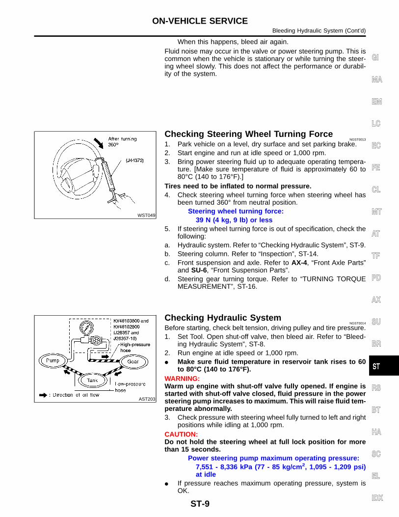
Checking Steering Wheel Turning ForceNGST0013
1. Park vehicle on a level, dry surface and set parking brake.2. Start engine and run at idle speed or 1,000 rpm.3. Bring power steering fluid up to adequate operating tempera-
ture. [Make sure temperature of fluid is approximately 60 to80°C (140 to 176°F).]
Tires need to be inflated to normal pressure.4. Check steering wheel turning force when steering wheel has
been turned 360° from neutral position.Steering wheel turning force:
39 N (4 kg, 9 lb) or less5. If steering wheel turning force is out of specification, check the
following:a. Hydraulic system. Refer to “Checking Hydraulic System”, ST-9.b. Steering column. Refer to “Inspection”, ST-14.c. Front suspension and axle. Refer to AX-4, “Front Axle Parts”
and SU-6, “Front Suspension Parts”.d. Steering gear turning torque. Refer to “TURNING TORQUE
MEASUREMENT”, ST-16.
AST203
Checking Hydraulic SystemNGST0014
Before starting, check belt tension, driving pulley and tire pressure.1. Set Tool. Open shut-off valve, then bleed air. Refer to “Bleed-
ing Hydraulic System”, ST-8.2. Run engine at idle speed or 1,000 rpm.� Make sure fluid temperature in reservoir tank rises to 60
to 80°C (140 to 176°F).WARNING:Warm up engine with shut-off valve fully opened. If engine isstarted with shut-off valve closed, fluid pressure in the powersteering pump increases to maximum. This will raise fluid tem-perature abnormally.3. Check pressure with steering wheel fully turned to left and right
positions while idling at 1,000 rpm.CAUTION:Do not hold the steering wheel at full lock position for morethan 15 seconds.
Power steering pump maximum operating pressure:7,551 - 8,336 kPa (77 - 85 kg/cm2, 1,095 - 1,209 psi)at idle
� If pressure reaches maximum operating pressure, system isOK.
GI
MA
EM
LC
EC
FE
CL
MT
AT
TF
PD
AX
SU
BR
RS
BT
HA
SC
EL
IDX
ON-VEHICLE SERVICEBleeding Hydraulic System (Cont’d)
ST-9
� If pressure increases above maximum operating pressure,check power steering pump flow control valve. Refer to“Components”, ST-18.
4. If power steering pressure is below the maximum operatingpressure, slowly close shut-off valve and check pressureagain.
CAUTION:Do not close shut-off valve for more than 15 seconds.� If pressure increases to maximum operating pressure, gear is
damaged. Refer to “Removal and Installation”, ST-15.� If pressure remains below maximum operating pressure, pump
is damaged. Refer to “Components”, ST-18.5. After checking hydraulic system, remove Tool and add fluid as
necessary. Completely bleed air out of system. Refer to“Bleeding Hydraulic System”, ST-8.
ON-VEHICLE SERVICEChecking Hydraulic System (Cont’d)
ST-10
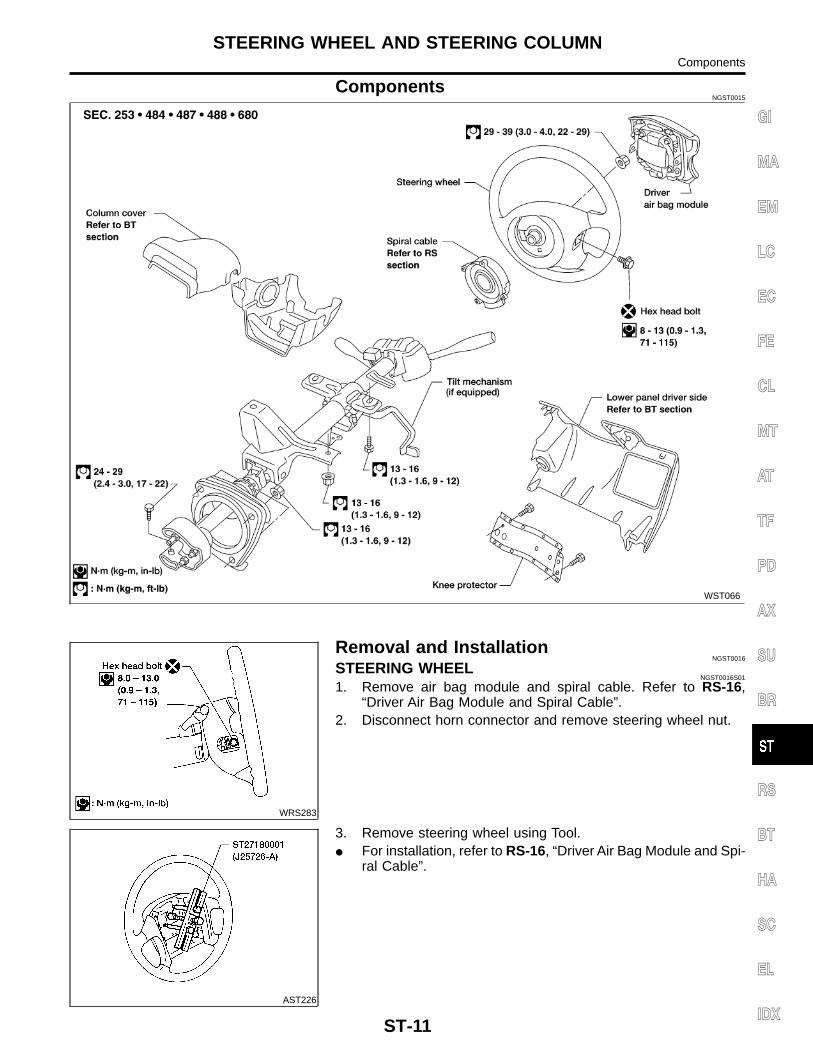
ComponentsNGST0015
WST066
WRS283
Removal and InstallationNGST0016
STEERING WHEELNGST0016S01
1. Remove air bag module and spiral cable. Refer to RS-16,“Driver Air Bag Module and Spiral Cable”.
2. Disconnect horn connector and remove steering wheel nut.
AST226
3. Remove steering wheel using Tool.� For installation, refer to RS-16, “Driver Air Bag Module and Spi-
ral Cable”.
GI
MA
EM
LC
EC
FE
CL
MT
AT
TF
PD
AX
SU
BR
RS
BT
HA
SC
EL
IDX
STEERING WHEEL AND STEERING COLUMNComponents
ST-11
STEERING COLUMNNGST0016S02
RemovalNGST0016S0201
CAUTION:� The rotation of the spiral cable (SRS “AIR BAG” compo-
nent part) is limited. If the steering gear must be removed,set the front wheels in the straight-ahead direction.Do not rotate the steering column while the steering gearis removed.
� Remove the steering wheel before removing the steeringlower joint to avoid damaging the SRS spiral cable. Referto “STEERING WHEEL”, ST-11.
1. Remove steering wheel. Refer to “STEERING WHEEL”,ST-11.
indicator.4. Disconnect combination switch electrical connectors and air
bag harness connector.5. Remove knee protector.6. Disconnect ignition switch and shift lock solenoid connectors.7. Disconnect shift cable.8. Remove bolt from lower joint.9. Remove two steering column bolts and remove steering col-
umn.
SST666A
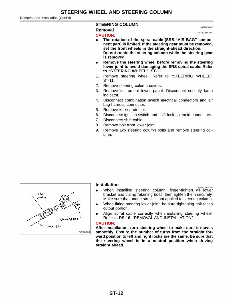
InstallationNGST0016S0202
� When installing steering column, finger-tighten all lowerbracket and clamp retaining bolts; then tighten them securely.Make sure that undue stress is not applied to steering column.
� When fitting steering lower joint, be sure tightening bolt facescutout portion.
� Align spiral cable correctly when installing steering wheel.Refer to RS-16, “REMOVAL AND INSTALLATION”.
CAUTION:After installation, turn steering wheel to make sure it movessmoothly. Ensure the number of turns from the straight for-ward position to left and right locks are the same. Be sure thatthe steering wheel is in a neutral position when drivingstraight ahead.
STEERING WHEEL AND STEERING COLUMNRemoval and Installation (Cont’d)
ST-12
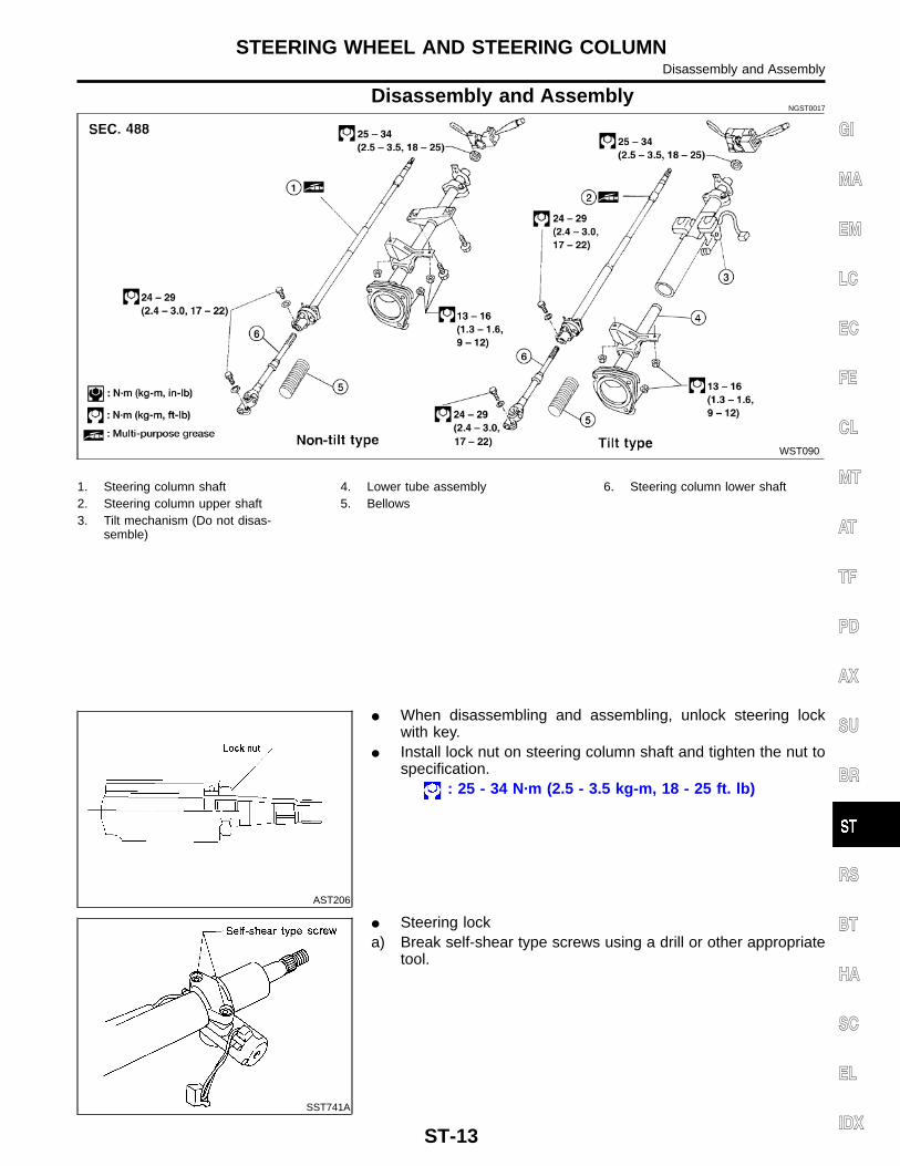
Disassembly and AssemblyNGST0017
WST090
1. Steering column shaft2. Steering column upper shaft3. Tilt mechanism (Do not disas-
semble)
4. Lower tube assembly5. Bellows
6. Steering column lower shaft
AST206
� When disassembling and assembling, unlock steering lockwith key.
� Install lock nut on steering column shaft and tighten the nut tospecification.
: 25 - 34 N·m (2.5 - 3.5 kg-m, 18 - 25 ft. lb)
SST741A
� Steering locka) Break self-shear type screws using a drill or other appropriate
tool.
GI
MA
EM
LC
EC
FE
CL
MT
AT
TF
PD
AX
SU
BR
RS
BT
HA
SC
EL
IDX
STEERING WHEEL AND STEERING COLUMNDisassembly and Assembly
ST-13
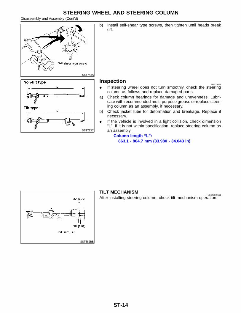
SST742A
b) Install self-shear type screws, then tighten until heads breakoff.
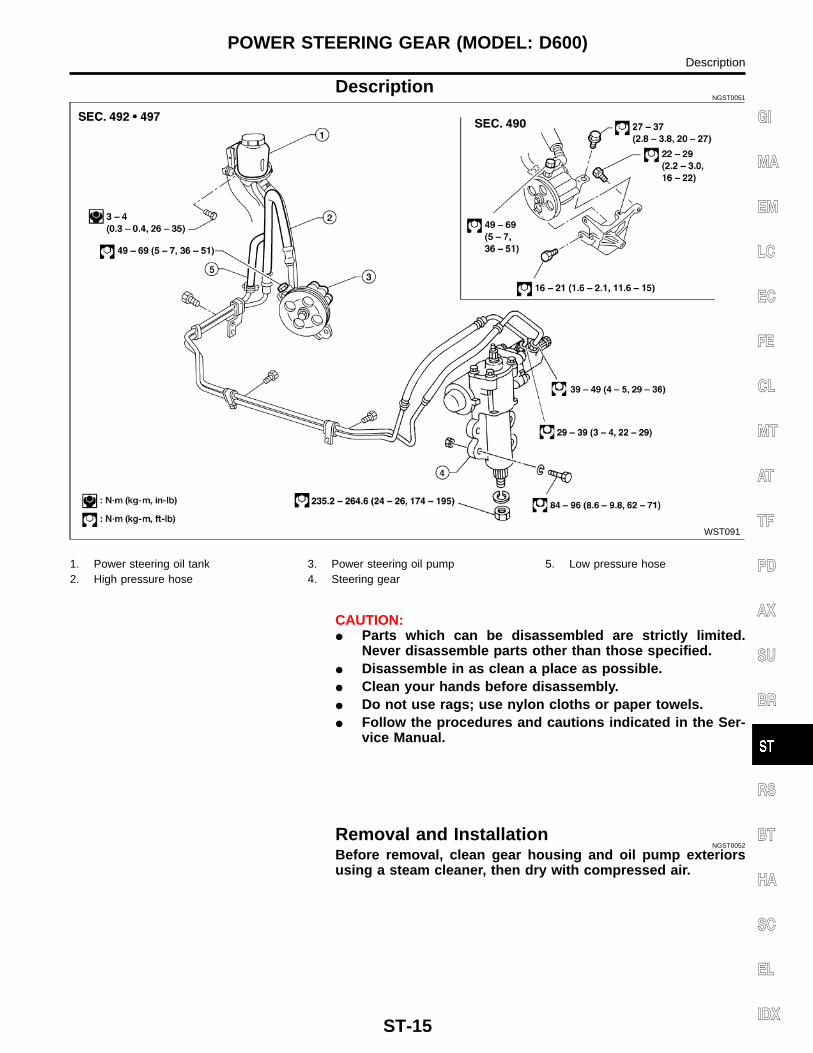
SST723C
InspectionNGST0018
� If steering wheel does not turn smoothly, check the steeringcolumn as follows and replace damaged parts.
a) Check column bearings for damage and unevenness. Lubri-cate with recommended multi-purpose grease or replace steer-ing column as an assembly, if necessary.
b) Check jacket tube for deformation and breakage. Replace ifnecessary.
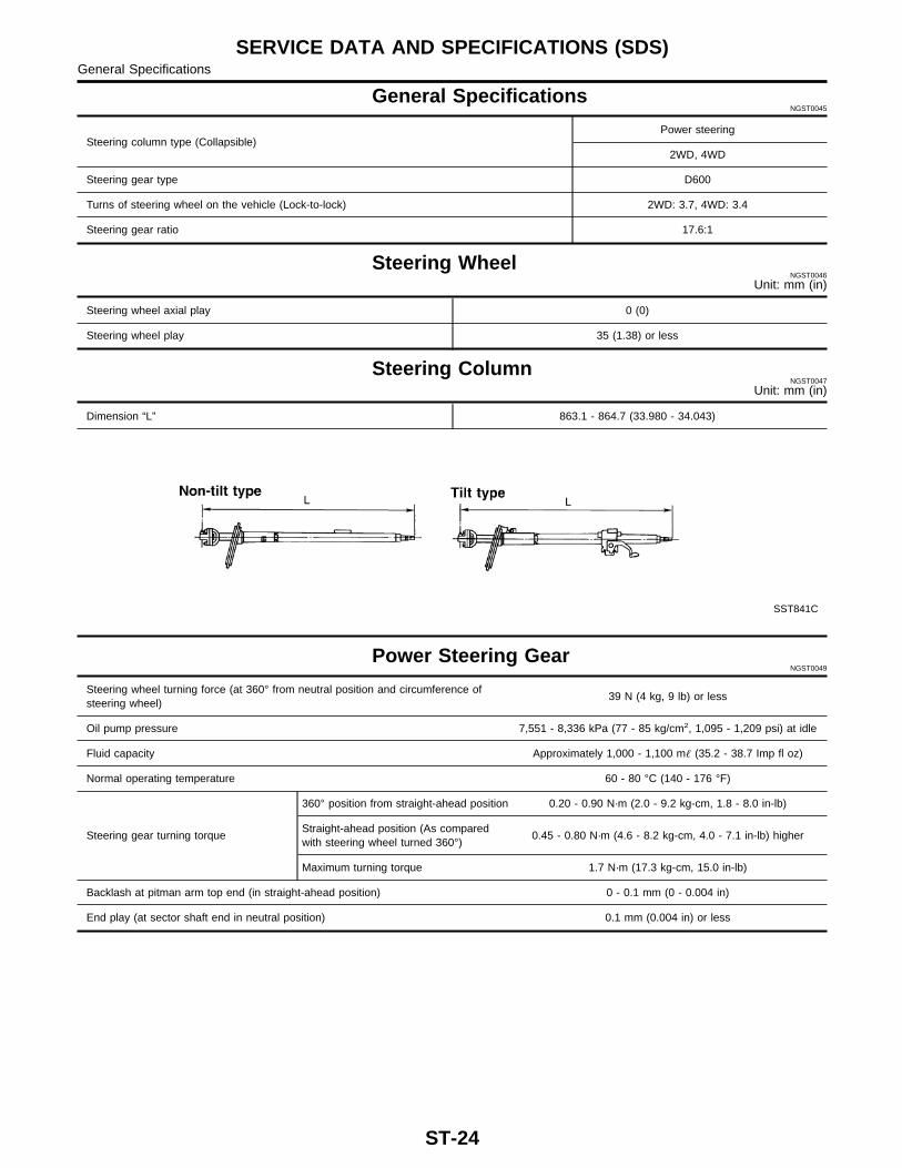
� If the vehicle is involved in a light collision, check dimension“L”. If it is not within specification, replace steering column asan assembly.
Column length “L”:863.1 - 864.7 mm (33.980 - 34.043 in)
SST582BB
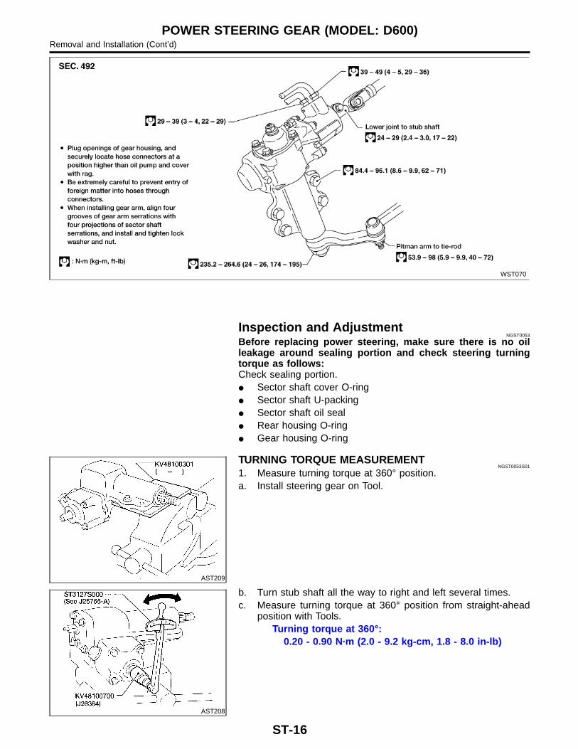
TILT MECHANISMNGST0018S01
After installing steering column, check tilt mechanism operation.
STEERING WHEEL AND STEERING COLUMNDisassembly and Assembly (Cont’d)
ST-14
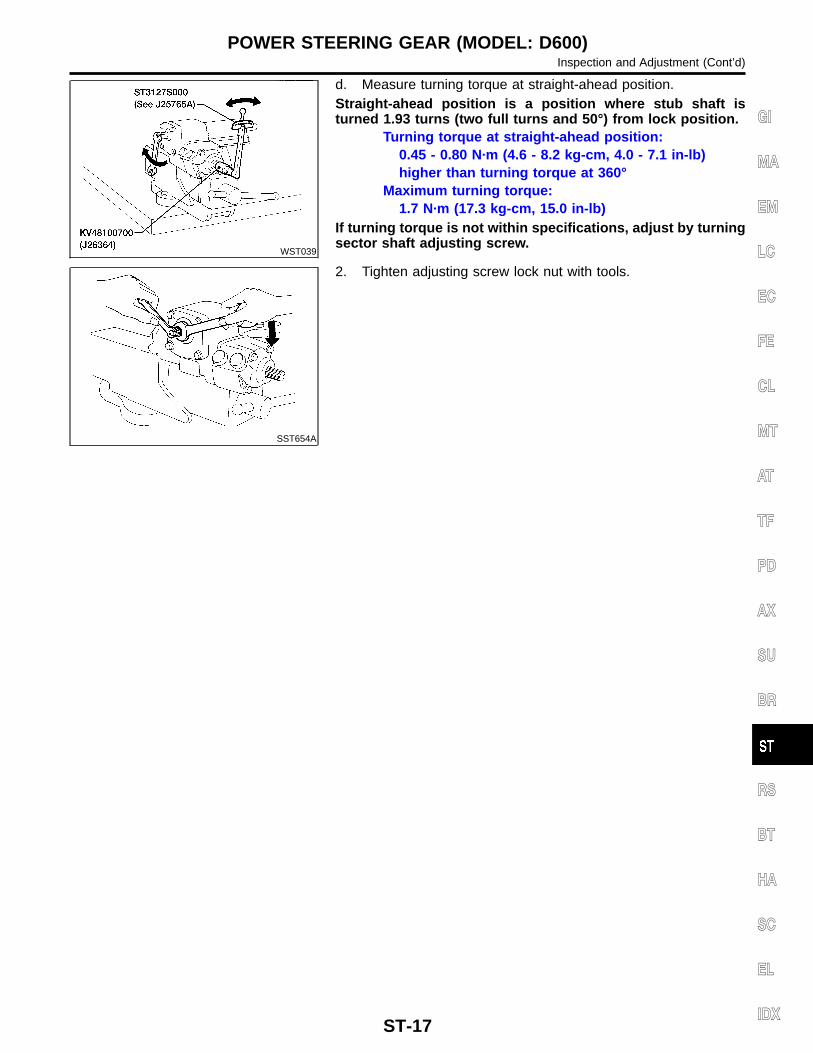
DescriptionNGST0051
WST091
1. Power steering oil tank2. High pressure hose
3. Power steering oil pump4. Steering gear
5. Low pressure hose
CAUTION:� Parts which can be disassembled are strictly limited.
Never disassemble parts other than those specified.� Disassemble in as clean a place as possible.� Clean your hands before disassembly.� Do not use rags; use nylon cloths or paper towels.� Follow the procedures and cautions indicated in the Ser-
vice Manual.
Removal and InstallationNGST0052
Before removal, clean gear housing and oil pump exteriorsusing a steam cleaner, then dry with compressed air.
GI
MA
EM
LC
EC
FE
CL
MT
AT
TF
PD
AX
SU
BR
RS
BT
HA
SC
EL
IDX
POWER STEERING GEAR (MODEL: D600)Description
ST-15
WST070
Inspection and AdjustmentNGST0053
Before replacing power steering, make sure there is no oilleakage around sealing portion and check steering turningtorque as follows:Check sealing portion.� Sector shaft cover O-ring� Sector shaft U-packing� Sector shaft oil seal� Rear housing O-ring� Gear housing O-ring
AST209
TURNING TORQUE MEASUREMENTNGST0053S01
1. Measure turning torque at 360° position.a. Install steering gear on Tool.
AST208
b. Turn stub shaft all the way to right and left several times.c. Measure turning torque at 360° position from straight-ahead
POWER STEERING GEAR (MODEL: D600)Removal and Installation (Cont’d)
ST-16
WST039
d. Measure turning torque at straight-ahead position.Straight-ahead position is a position where stub shaft isturned 1.93 turns (two full turns and 50°) from lock position.
Turning torque at straight-ahead position:0.45 - 0.80 N·m (4.6 - 8.2 kg-cm, 4.0 - 7.1 in-lb)higher than turning torque at 360°
Maximum turning torque:1.7 N·m (17.3 kg-cm, 15.0 in-lb)
If turning torque is not within specifications, adjust by turningsector shaft adjusting screw.
SST654A
2. Tighten adjusting screw lock nut with tools.
GI
MA
EM
LC
EC
FE
CL
MT
AT
TF
PD
AX
SU
BR
RS
BT
HA
SC
EL
IDX
POWER STEERING GEAR (MODEL: D600)Inspection and Adjustment (Cont’d)
ST-17
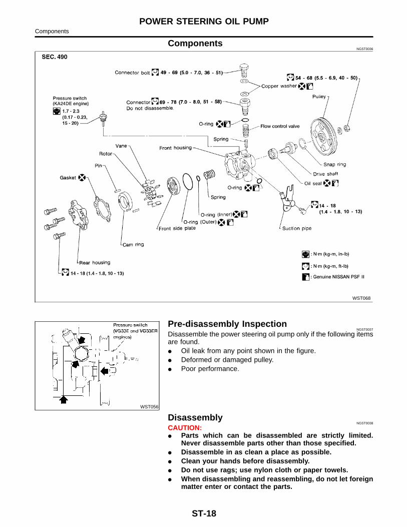
ComponentsNGST0036
WST068
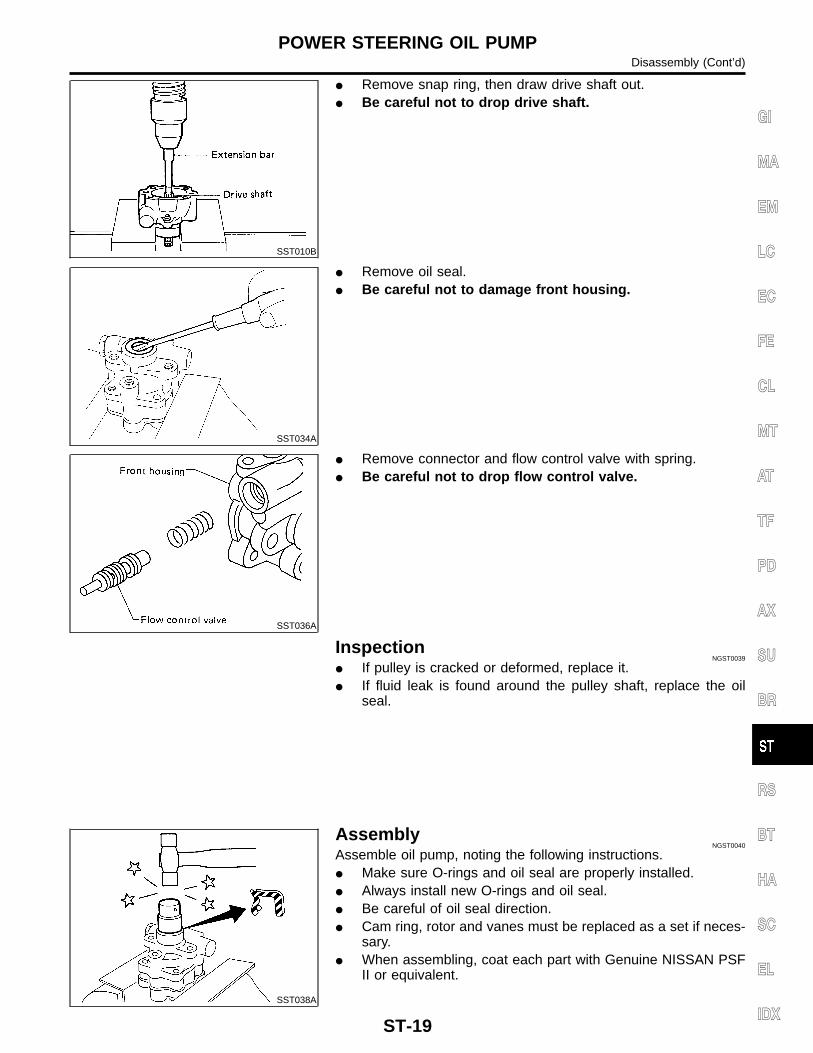
WST056
Pre-disassembly InspectionNGST0037
Disassemble the power steering oil pump only if the following itemsare found.� Oil leak from any point shown in the figure.� Deformed or damaged pulley.� Poor performance.
DisassemblyNGST0038
CAUTION:� Parts which can be disassembled are strictly limited.
Never disassemble parts other than those specified.� Disassemble in as clean a place as possible.� Clean your hands before disassembly.� Do not use rags; use nylon cloth or paper towels.� When disassembling and reassembling, do not let foreign
matter enter or contact the parts.
POWER STEERING OIL PUMPComponents
ST-18
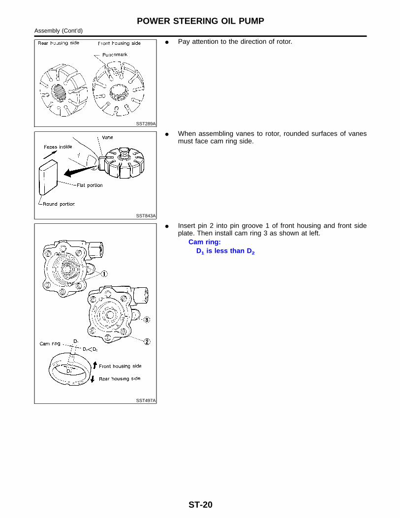
SST010B
� Remove snap ring, then draw drive shaft out.� Be careful not to drop drive shaft.
SST034A
� Remove oil seal.� Be careful not to damage front housing.
SST036A
� Remove connector and flow control valve with spring.� Be careful not to drop flow control valve.
InspectionNGST0039
� If pulley is cracked or deformed, replace it.� If fluid leak is found around the pulley shaft, replace the oil
seal.
SST038A
AssemblyNGST0040
Assemble oil pump, noting the following instructions.� Make sure O-rings and oil seal are properly installed.� Always install new O-rings and oil seal.� Be careful of oil seal direction.� Cam ring, rotor and vanes must be replaced as a set if neces-
sary.� When assembling, coat each part with Genuine NISSAN PSF
II or equivalent.
GI
MA
EM
LC
EC
FE
CL
MT
AT
TF
PD
AX
SU
BR
RS
BT
HA
SC
EL
IDX
POWER STEERING OIL PUMPDisassembly (Cont’d)
ST-19
SST289A
� Pay attention to the direction of rotor.
SST843A
� When assembling vanes to rotor, rounded surfaces of vanesmust face cam ring side.
SST497A
� Insert pin 2 into pin groove 1 of front housing and front sideplate. Then install cam ring 3 as shown at left.
Cam ring:D1 is less than D2
POWER STEERING OIL PUMPAssembly (Cont’d)
ST-20
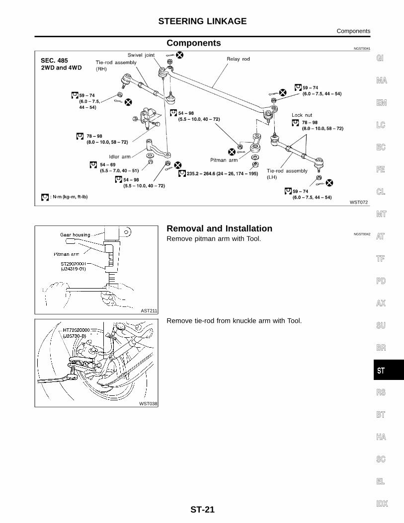
ComponentsNGST0041
WST072
AST211
Removal and InstallationNGST0042
Remove pitman arm with Tool.
WST038
Remove tie-rod from knuckle arm with Tool.
GI
MA
EM
LC
EC
FE
CL
MT
AT
TF
PD
AX
SU
BR
RS
BT
HA
SC
EL
IDX
STEERING LINKAGEComponents
ST-21
AST250
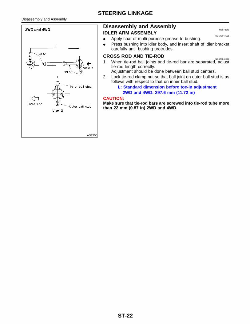
Disassembly and AssemblyNGST0043
IDLER ARM ASSEMBLYNGST0043S01
� Apply coat of multi-purpose grease to bushing.� Press bushing into idler body, and insert shaft of idler bracket
carefully until bushing protrudes.
CROSS ROD AND TIE-RODNGST0043S02
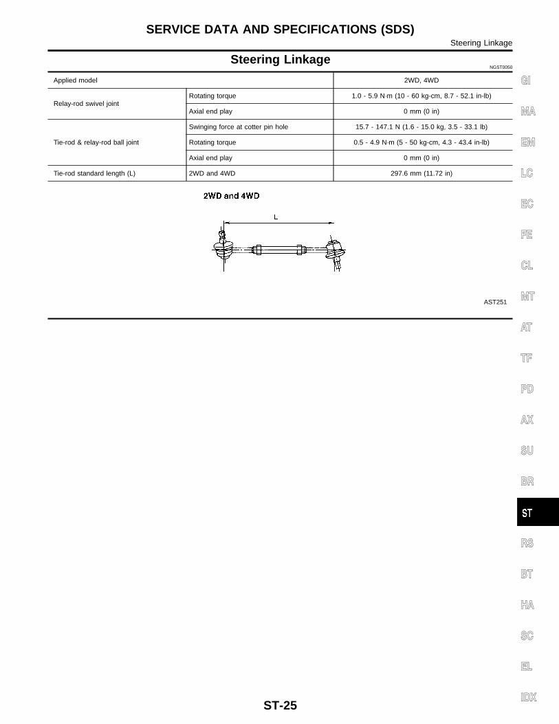
1. When tie-rod ball joints and tie-rod bar are separated, adjusttie-rod length correctly.Adjustment should be done between ball stud centers.
2. Lock tie-rod clamp nut so that ball joint on outer ball stud is asfollows with respect to that on inner ball stud.
L: Standard dimension before toe-in adjustment2WD and 4WD: 297.6 mm (11.72 in)
CAUTION:Make sure that tie-rod bars are screwed into tie-rod tube morethan 22 mm (0.87 in) 2WD and 4WD.
STEERING LINKAGEDisassembly and Assembly
ST-22
SST827C
SFA817A
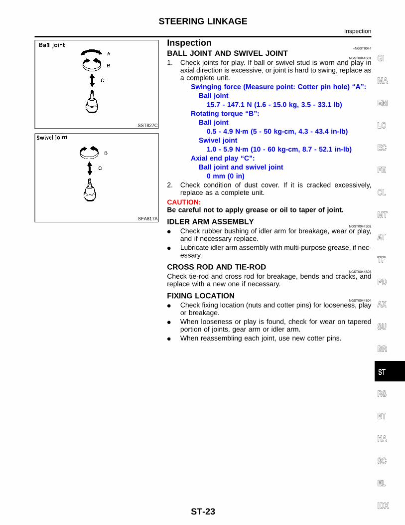
Inspection=NGST0044
BALL JOINT AND SWIVEL JOINTNGST0044S01
1. Check joints for play. If ball or swivel stud is worn and play inaxial direction is excessive, or joint is hard to swing, replace asa complete unit.
Swinging force (Measure point: Cotter pin hole) “A”:Ball joint