Supplementary information On/off switching of bit readout in bias-enhanced tunnel magneto-Seebeck effect Alexander Boehnke* 1 , Marius Milnikel 2 , Marvin von der Ehe 2 , Christian Franz 3 , Vladyslav Zbarsky 2 , Michael Czerner 3 , Karsten Rott 1 , Andy Thomas 4 , Christian Heiliger 3 , Günter Reiss 1 , and Markus Münzenberg 2 1. Center for Spinelectronic Materials and Devices, Physics Department, Bielefeld University, Universitätsstrasse 25, Bielefeld, Germany 2. I. Physikalisches Institut, Georg-August-Universität Göttingen, Friedrich-Hund-Platz 1, Göttingen, Germany and Institut für Physik, Ernst-Moritz-Arndt Universität, Felix-Hausdorff-Str. 6, Greifswald, Germany 3. I. Physikalisches Institut, Justus-Liebig-Universität Gießen, Heinrich-Buff-Ring 16, Gießen, Germany 4. Thin films and Physics of Nanostructures, Physics Department, Bielefeld University, Universitätsstrasse 25, Bielefeld, Germany and Institut für Physik, Johannes Gutenberg Universität Mainz, Staudingerweg 7, Mainz, Germany *[email protected]Components of the measured signal We applied an external DC bias voltage V while simultaneously heating the top of the junction with a modulated laser. The current !" , ! , ! during the heating periods differs from the current !"" , ! running through the non-heated MTJ. !"" can be interpreted as a DC background current generated by the DC bias voltage and depends on the resistance !"" (! ) for the non-heated MTJ at temperature ! . !" is an AC current modulated on top of !"" due to the heating. It consists of a Seebeck current generated by the temperature difference ∆= ! − ! and a current created by the bias voltage dependent on the resistance !" () for the mean temperature = ! ! (! + ! ) during the heating periods. The amplitude of the AC current can be expressed by:
Transcript
Supplementary information
On/off switching of bit readout in bias-enhanced tunnel magneto-Seebeck effect
Alexander Boehnke*1, Marius Milnikel2, Marvin von der Ehe2, Christian Franz3, Vladyslav Zbarsky2,
Michael Czerner3, Karsten Rott1, Andy Thomas4, Christian Heiliger3, Günter Reiss1, and Markus
Münzenberg2
1. Center for Spinelectronic Materials and Devices, Physics Department, Bielefeld University, Universitätsstrasse 25, Bielefeld,
Germany
2. I. Physikalisches Institut, Georg-August-Universität Göttingen, Friedrich-Hund-Platz 1, Göttingen, Germany and Institut für
Physik, Ernst-Moritz-Arndt Universität, Felix-Hausdorff-Str. 6, Greifswald, Germany
3. I. Physikalisches Institut, Justus-Liebig-Universität Gießen, Heinrich-Buff-Ring 16, Gießen, Germany
4. Thin films and Physics of Nanostructures, Physics Department, Bielefeld University, Universitätsstrasse 25, Bielefeld,
Germany and Institut für Physik, Johannes Gutenberg Universität Mainz, Staudingerweg 7, Mainz, Germany
From this equation it becomes obvious that the amplitude of the AC current consists of two
contributions: ∆𝐼∆! results from a change in the resistance of the junction caused by the change of
the mean temperature. This contribution rises linearly with applied bias voltage and vanishes at
zero bias. ∆𝐼∆! is created by the temperature gradient and is thus related to the Seebeck effect.
Eq. (1) in the main text can be deduced from Eq. (i) and describes the processes relevant for the
measurements.
In the experimental setup we use a lock-in amplifier to detect the currents. Therefore we can
directly measure the amplitude of ∆𝐼. Nevertheless, Eq. (1) exhibits that the signal contains
information on the Seebeck effect and on the change of the resistance. They can only be
separated by their symmetry. The non-Seebeck signal behaves linearly with increasing bias when
the resistance is assumed to be constant with respect to the applied voltages (Fig. 2 c).
Accordingly, we can apply a linear model to separate this contribution from the overall current
𝛥𝐼.
Direct and indirect determination of the Seebeck voltages
A direct measurement of the Seebeck voltage 𝑆𝛥𝑇 is only possible when no external bias voltage
is applied to the MTJ, but 𝑆𝛥𝑇 can also be determined indirectly from the current and the
resistance measurements (Eq. 1)1,2. Accordingly, we can compare both techniques when no bias
voltage is applied to the MTJ. For zero bias voltage (𝑉 = 0 mV) Eq. (1) gives 𝑆𝛥𝑇 = 1/𝐺 ⋅ 𝛥𝐼 =
𝑅 ⋅ 𝛥𝐼 . Fig. I a shows a comparison of the directly and indirectly determined 𝑆𝛥𝑇. The spikes in
the curve of the indirect determination occur because of slight differences in the switching fields
for the bTMS (current) and TMR effect measurements (Fig. I b & c). The measured and
indirectly determined Seebeck voltages have nearly the same height. Hence, a determination of
the 𝑆𝛥𝑇 from the current with this method (based on Eq. (1)) leads to the correct deduction of the
Seebeck coefficients and their dependence on the bias voltage.
Fig I Directly and indirectly determined Seebeck voltages without bias: a The measured Seebeck voltage (𝑺𝜟𝑻) and the 𝑺𝜟𝑻 for 𝑽𝐛𝐢𝐚𝐬 = 𝟎 𝐦𝐕 determined from the current and resistance measurements show the same switching fields and the same height. The corresponding TMS ratio is given on the right. b Dependence of the resistance 𝑹 on the applied magnetic field and corresponding TMR ratio. The measurements were performed with a bias voltage of 10 mV. c Dependence of the Seebeck current 𝜟𝑰 on the applied magnetic field without bias voltage and corresponding bTMS ratio. Accordingly, the measured current 𝜟𝑰 = (𝟏/𝑹𝒐𝒏) ⋅ 𝑺𝜟𝑻 is proportional to the Seebeck coefficient and the inverse of the resistance (𝑺/𝑹). Hence, the measurements of b and c can be used to determine the blue curve in a.
On/off characteristics of the current
In a DC measurement, the current through the MTJ can be written as: 3,4
𝐼P,AP = 𝐺P,AP(𝑉bias + 𝑆P,AP𝛥𝑇) (ii)
When we set 𝑉bias = −𝑆P𝛥𝑇 the measured current 𝐼P can be set to zero. If we now reverse the
magnetic state of the MTJ under a fixed bias voltage, we will find 𝐼!" = 𝐺!" 𝑆!" − 𝑆! 𝛥𝑇 which
a b14121086R
esistance(kΩ)
-20 -10 0 10 20Magnetic field (mT)
16012080400
TMR(%)
9
8
7
6
5
S∆T(µV)
-20 -10 0 10 20Magnetic field (mT)
-30
-20
-10
0
10
20
30
TMS(%)
measuredR•∆I
1.0
0.8
0.6
∆I(nA)
-20 -10 0 10 20Magnetic field (mT)
-50-40-30-20-100 bTM
S(%)
c
is non-zero.
In our experiment we use an AC heating and measure the difference between the current when
the heating is switched on and off. Accordingly, we have to rewrite Eq. (ii) to Eq. (1):
𝛥𝐼 =1
𝑅!,!" − 𝛥𝑅!,!"𝑆!,!"𝛥𝑇 +
𝛥𝑅!,!"𝑅!,!"
𝑉
To get a zero 𝛥𝐼! we have to set the external bias voltage to 𝑉 = −𝑆!𝛥𝑇 ⋅ (𝑅!/𝛥𝑅!) . When the
magnetic state of the MTJ is reversed and 𝑉 is fixed, the current changes to
𝛥𝐼!" =!
!!"!!"!"𝑆!"𝛥𝑇 +
!!!"!!"
⋅ −𝑆!𝛥𝑇 ⋅ !!!!!
(iii)
=1
𝑅!" − 𝛥𝑅!"𝑆!" −
𝛥𝑅!" ⋅ 𝑅!𝛥𝑅! ⋅ 𝑅!"
!
𝑆! 𝛥𝑇.
As a first approximation, we can use the resistance determined by the differential conductance
measurements (Fig. 2 b) and the Seebeck voltages measured without a bias voltage (Fig. I a).
This gives a factor 𝛼 for 𝑆! of approximately 6.69. Inserting 𝑆!"𝛥𝑇 ≈ 8 µμV and 𝑆!𝛥𝑇 ≈ 6.8 µμV
this yields a current in the AP state of the MTJ of 𝛥𝐼!" ≈ 3 nA. A comparable value for 𝛥𝐼!" has
been measured for a bias voltage of -10 mV, where we obtain a 𝛥𝐼! of approximately zero (Fig. 2
a & b) in the P state of the MTJ. A cancelation of the TMR and TMS effects in the AP state is not
seen for this MTJ. When the MTJ is switched from the P to the AP state, the changing resistances
contribute a factor of 𝛼 ≈ 6.7 to Eq. (iii), whereas the Seebeck voltages change by a factor of 1.2.
Hence, the bracket in Eq. (iii) is zero in the P state and non-zero in the AP state.
Peltier and Thomson effects
𝑄 = 𝛱 ∙ 𝐼!", 𝛱 = 𝑆𝑇. (iv)
For the correct interpretation of our results it is essential to calculate the heat current created by
the DC charge current IDC driven through the MTJ by the bias voltage (Peltier effect). The
amount of heat generated is directly proportional to the Peltier coefficient Π and, therefore, to the
Seebeck coefficient S of the MTJ. At temperatures of T ≈ 400 K the measured Seebeck
coefficients for CoFeB/MgO MTJs are in the range of 100 µVK-1 to 770 µVK−1 [1,8]. For a
minimal measured resistance of 6 kΩ and a maximal applied bias voltage of 300 mV, this yields a
maximum heat current of Qmax ≈ 16 µW. Thus, the heat generated by Peltier effects can be
neglected, as a laser with a power of up to 150 mW is focused on top of the MTJ, creating a much
larger temperature difference across the barrier than the Peltier effect.
Furthermore, a Thomson heat is generated by the temperature gradient and the current density j
caused by the bias and the Seebeck voltages across the MTJ. This effect is described by the heat
production rate per unit volume as
𝑞 = −𝛫𝑗𝛻𝑇,𝛫 = 𝑇 !!!!
, (v)
when Joule heating and thermal conductivity are not included. 𝛫 is the Thomson coefficient that
is non-zero for Seebeck coefficients which depend on the temperature. For MTJs, the temperature
dependence of the Seebeck coefficients has not been experimentally determined. Ab initio
calculations5 show that between 300 K and 400 K the Seebeck coefficients remain nearly
constant for most Co-Fe compositions4. This yields dS/dT ≈ 0 and therefore Thomson effects
should vanish.
Tunnel magnetoresistance
Resistance measurements were performed with a Keithley 2400 Sourcemeter. A constant bias
voltage is applied to the MTJ while the current is measured. An external magnetic field is used to
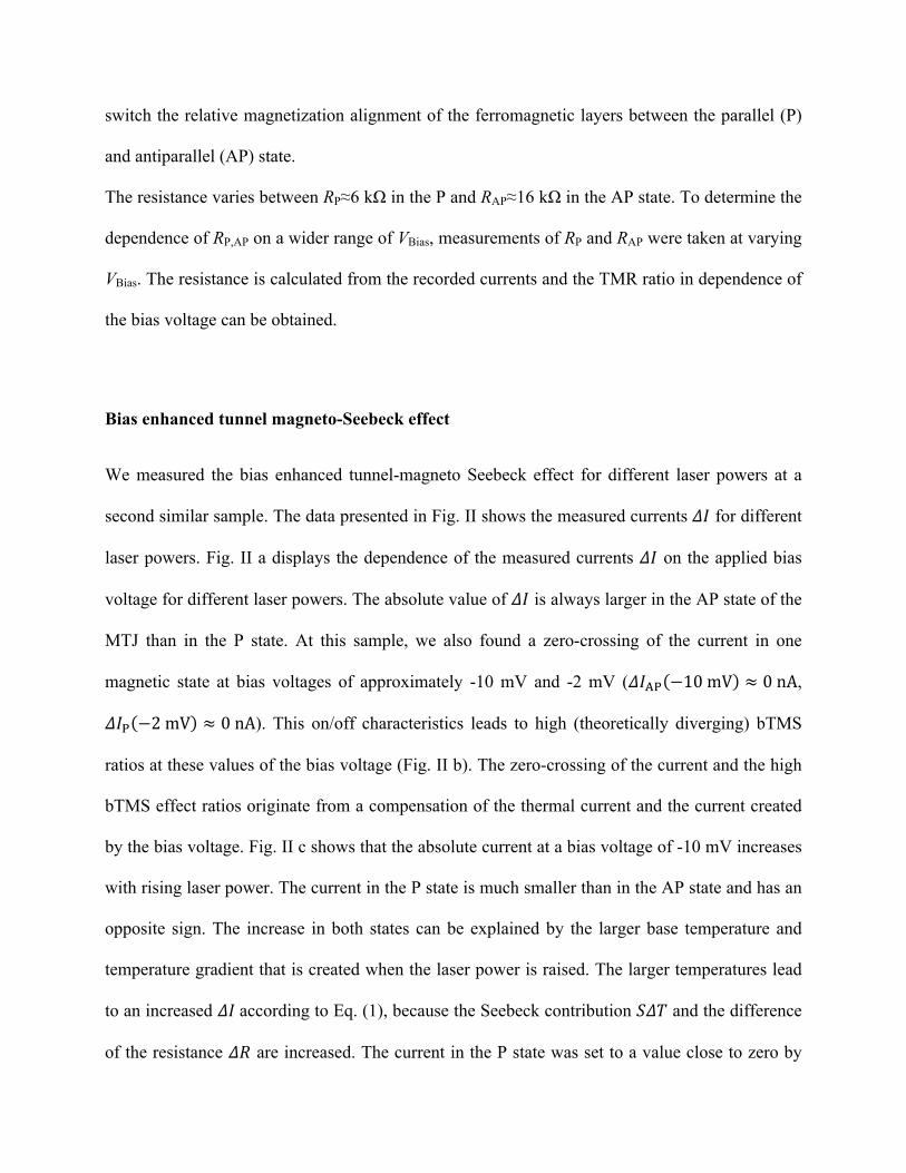
switch the relative magnetization alignment of the ferromagnetic layers between the parallel (P)
and antiparallel (AP) state.
The resistance varies between RP≈6 kΩ in the P and RAP≈16 kΩ in the AP state. To determine the
dependence of RP,AP on a wider range of VBias, measurements of RP and RAP were taken at varying
VBias. The resistance is calculated from the recorded currents and the TMR ratio in dependence of
the bias voltage can be obtained.
Bias enhanced tunnel magneto-Seebeck effect
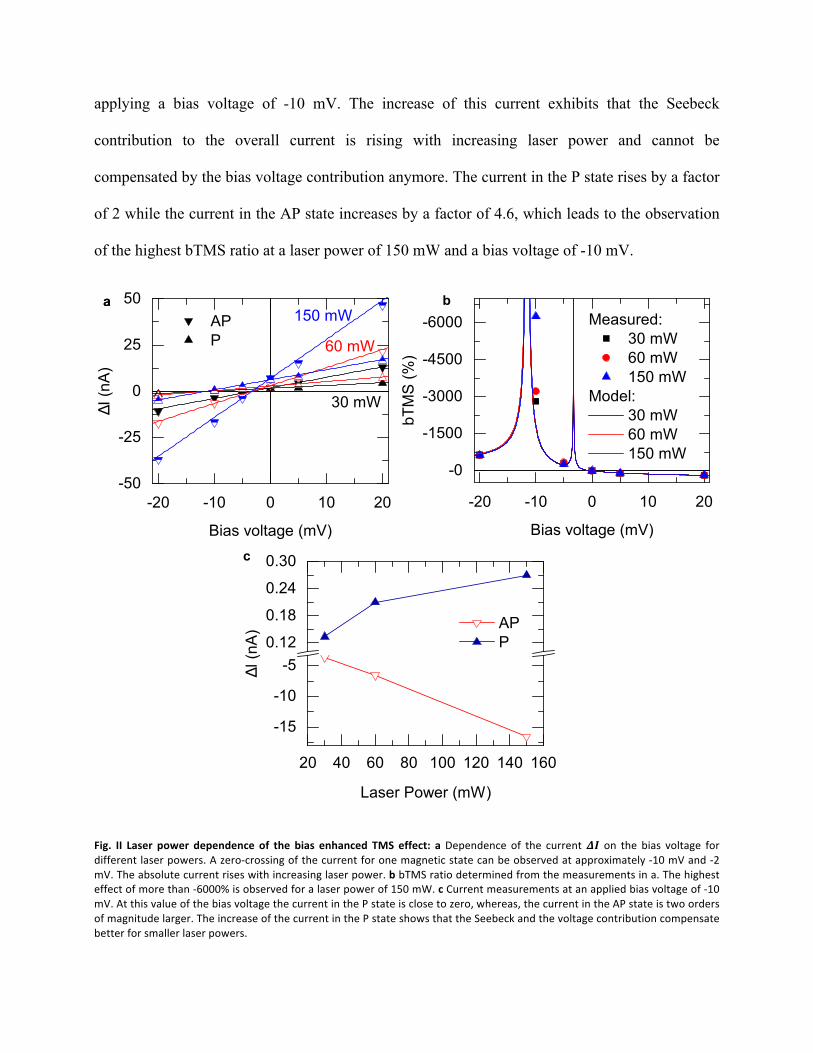
We measured the bias enhanced tunnel-magneto Seebeck effect for different laser powers at a
second similar sample. The data presented in Fig. II shows the measured currents 𝛥𝐼 for different
laser powers. Fig. II a displays the dependence of the measured currents 𝛥𝐼 on the applied bias
voltage for different laser powers. The absolute value of 𝛥𝐼 is always larger in the AP state of the
MTJ than in the P state. At this sample, we also found a zero-crossing of the current in one
magnetic state at bias voltages of approximately -10 mV and -2 mV (𝛥𝐼!" −10 mV ≈ 0 nA,
𝛥𝐼! −2 mV ≈ 0 nA). This on/off characteristics leads to high (theoretically diverging) bTMS
ratios at these values of the bias voltage (Fig. II b). The zero-crossing of the current and the high
bTMS effect ratios originate from a compensation of the thermal current and the current created
by the bias voltage. Fig. II c shows that the absolute current at a bias voltage of -10 mV increases
with rising laser power. The current in the P state is much smaller than in the AP state and has an
opposite sign. The increase in both states can be explained by the larger base temperature and
temperature gradient that is created when the laser power is raised. The larger temperatures lead
to an increased 𝛥𝐼 according to Eq. (1), because the Seebeck contribution 𝑆𝛥𝑇 and the difference
of the resistance 𝛥𝑅 are increased. The current in the P state was set to a value close to zero by
applying a bias voltage of -10 mV. The increase of this current exhibits that the Seebeck
contribution to the overall current is rising with increasing laser power and cannot be
compensated by the bias voltage contribution anymore. The current in the P state rises by a factor
of 2 while the current in the AP state increases by a factor of 4.6, which leads to the observation
of the highest bTMS ratio at a laser power of 150 mW and a bias voltage of -10 mV.
Fig. II Laser power dependence of the bias enhanced TMS effect: a Dependence of the current 𝜟𝑰 on the bias voltage for different laser powers. A zero-‐crossing of the current for one magnetic state can be observed at approximately -‐10 mV and -‐2 mV. The absolute current rises with increasing laser power. b bTMS ratio determined from the measurements in a. The highest effect of more than -‐6000% is observed for a laser power of 150 mW. c Current measurements at an applied bias voltage of -‐10 mV. At this value of the bias voltage the current in the P state is close to zero, whereas, the current in the AP state is two orders of magnitude larger. The increase of the current in the P state shows that the Seebeck and the voltage contribution compensate better for smaller laser powers.
-20 -10 0 10 20
-0
-1500
-3000
-4500
-6000 Measured:30 mW60 mW150 mW
Model:30 mW60 mW150 mW
bTMS(%)
Bias voltage (mV)
-20 -10 0 10 20-50
-25
0
25
50
30 mW
60 mWAPP
∆I(nA)
Bias voltage (mV)
150 mW
20 40 60 80 100 120 140 160
-15
-10
-50.12
0.18
0.24
0.30
∆I(nA)
Laser Power (mW)
APP
aa b
c
Contributions of bias voltage and Seebeck voltage signal
In the experiment we found a zero current singal in the P state at a bias voltage of -10 mV
(𝛥𝐼! −10 mV ≈ 0 nA). We can calculate the corresponding Seebeck voltage 𝑆!𝛥𝑇 that is
compensated by the bias votlage of -10 mV using Eq. (1). Further we need the measured
conductances for the MTJ in the P state 𝐺!" ≈ 194.97 µμS and 𝐺!"" ≈ 194.70 µμS when the laser is
switched on or off.
𝛥𝐼𝐺!"
−𝐺!" − 𝐺!""
𝐺!"𝑉 = 𝑆𝛥𝑇
𝑆!𝛥𝑇 ≈0.27 µμV194.97 µμV ⋅ −10 mV ≈ 13.85 µμV.
The same calculation can be done for the AP state of the MTJ where a bias voltage of -2 mV is
needed to componstate the current signal 𝛥𝐼!" −2 mV ≈ 0 nA. The conductances for the AP
sate are 𝐺!" ≈ 81.02 µμS and 𝐺!"" ≈ 80.18 µμS.
𝑆!"𝛥𝑇 ≈0.84 µμS81.02 µμS ⋅ −2 mV ≈ 20.8 µμV.
Because of the small factors 𝐺!" − 𝐺!"" /𝐺!" relatively high voltages in the millivolt regime are
needed to compensate the contirbution of the Seebeck voltages in the microvolt range to the
measured currents 𝛥𝐼. Seebeck voltages of some microvolts are measured at the investigated
junctions when no bias voltage is applied (Fig. I a).
Bibliography
1. Boehnke, A. et al. Time-resolved measurement of the tunnel magneto-Seebeck effect in a single magnetic tunnel junction. Rev. Sci. Instrum. 84, 063905 (2013).
2. Liebing, N. et al. Tunneling magneto thermocurrent in CoFeB/MgO/CoFeB based magnetic tunnel junctions. Appl. Phys. Lett. 102, 242413 (2013).
3. Johnson, M. Spin caloritronics and the thermomagnetoelectric system. Solid State Commun. 150, 543–547 (2010).
4. Johnson, M. & Silsbee, R. H. Thermodynamic analysis of interfacial transport and of the thermomagnetoelectric system. Phys. Rev. B 35, 4959–4972 (1987).
5. Heiliger, C., Franz, C. & Czerner, M. Ab initio studies of the tunneling magneto-Seebeck effect: Influence of magnetic material. Phys. Rev. B 87, 224412 (2013).