Page 1
Section VI. Employers Requirements 1
BIDDING DOCUMENT
FOR
SUPPLY, INSTALLATION AND COMMISSIONING OF
TESTING EQUIPMENT
BID PACKAGE NO.: UREDS-G-10B
UNDER IDA CREDIT NO. 5381-BD
VOLUME: II OF II
(SECTION VII: SCHEDULE OF REQUIREMENTS)
ISO 9001, ISO 14001 &
OHSAS 18001 Certified
BANGLADESH RURAL ELECTRIFICATION BOARD (BREB)
HEAD OFFICE, ACADEMIC BUILDING, 6TH
FLOOR NIKUNJA-2,
KHILKHET, DHAKA-1229
BANGLADESH
Page 2
Section VI. Employers Requirements 2
Bidding Document for
SUPPLY, INSTALLATION AND COMMISSIONING OF
TESTING EQUIPMENT
ICB No.: UREDS-G-10B
VOLUME: II OF II
(SCHEDULE OF REQUIREMENTS)
ISSUED ON: ________________
EMPLOYER: BANGLADESH RURAL ELECTRIFICATION
BOARD (BREB)
PROJECT: UREDS; DCSD (UP-GRADATION OF RURAL
ELECTRICITY DISTRIBUTION SYSTEM;
DHAKA, CHITTAGONG & SYLHET DIVISION)
PROJECT UNDER RURAL ELECTRICITY
TRANSMISSION AND DISTRIBUTION (T&D)
PROJECT OF IDA.
COUNTRY: BANGLADESH
Page 3
Section VI. Employers Requirements 3
VOLUME: IIOF II
(SCHEDULE OF REQUIREMENTS)
TABLE OF CONTENTS
SECTION VII: SCHEDULE OF REQUIREMENTS ...........................................................
Scope of Supply of Equipment and Installation Services by the Contractor ............... 4
Acceptance Testing Laboratory Equipment Specifications ......................................... 13
Page 4
Section VI. Employers Requirements 4
SECTION VII
SCOPE OF SUPPLY OF EQUIPMENT AND INSTALLATION
SERVICES BY THE SUPPLIER
GENERAL REQUIREMENTS
Page 5
Section VI. Employers Requirements 5
5
Scope of Work of Project:
1.0 Overview
The scope of work in this bidding document covers below given works on Turn-Key Basis
(TKB):
Laboratory Equipment: Design, supply, installation, testing, commissioning, training to
BREB staff and handing over of the material Acceptance Test Laboratories in fully
commissioned form to BREB. The laboratories equipment shall be incompliance with the
technical specifications as given in Section VI-Specifications of this document. The main
laboratory is comprising of thirteen (13) individual laboratories for testing different kind of
materials as described in this document.
Laboratory Equipment Installation, Testing and Commissioning: The overall scope of
work covers design, manufacture, quality assurance, inspection and testing, packaging for
export, insurance and shipment to site, complete construction, erection and installation of
testing equipment, bonding, earthing, shielding, setting to work, site testing and
commissioning of all the equipment necessary for operations in the designated "Acceptance
Test Laboratories" in the main building, on turnkey basis (TKB).
The detailed requirements of each item of laboratory equipment are given in the technical
specifications and guaranteed technical schedules. The Contractor shall provide a functioning
product complete in all respects and ready for use on a turnkey basis and shall remedy all
defects during the defect notification period of the equipment as per the contract. The
Contractor shall be responsible for providing equipment, which shall meet in all respects the
performance specifications and shall have satisfactory durability for the prevailing site
conditions.
The Contractor shall be responsible for ensuring that all items (materials and labor) required
for the safe efficient and satisfactory completion and functioning of the works (in accordance
with the specifications) are included in the bid price, whether individually described in the
specifications or not.
The site plans are as included in this document in "13-Section VI -Layout Plans" and the
location will also be identified on the ground during site visit. Each bidder shall visit the site
during bidding period. At least 10 days advance notice to BREB will be required.
Design: The detailed design arrangements of the materials, equipment and installation shall
be the responsibility of the Contractor/Supplier of equipment subject to the approval of the
designated committee of BREB with the recommendations of the Project Manager. The
Contractor/Supplier shall submit complete Civil, Electrical, Mechanical and other applicable
drawings, manuals, foundation designs (where applicable), specifications, BOQs and
supporting calculations etc. for review and approval, prior to commencing manufacturing,
construction and/or installation works.
The Bidders shall inspect site to confirm the scope of work.
Page 6
Section VI. Employers Requirements 6
6
Transportation and Storage: Transportation requirements, storage, suitable construction
tools, necessary equipment and all required materials for installation and connections as well
as testing and commissioning of laboratory equipment are included in the scope of work.
Layout Plans: The conceptual layout plans are provided in "13-Section VI -Layout Plans".
Floor Planning:
(i) Ground Floor:
a. Lab-5: Power Transformer Testing System-PTTS
b. Lab-6: Distribution Transformer Testing System -DTTS
c. Lab-7: High Voltage Electrical Testing
d. Lab-8: Mechanical Testing/Tensile Testing
e. Lab-9: Auto-Recloser/Circuit Breaker/ Fuse Links/Fuse Cut-Outs
Testing
f. Lab-10: Cable & Conductor Testing
g. Lab-11: Insulators Testing
h. Lab-12: Transformer Oil Testing
(ii) First Floor:
a. Lab-1: Single-Phase & Three-Phase meters Testing Facility
b. Lab-2: Current Transformers/Voltage Transformers (CT/PT) Testing
c. Lab-3: Lightning Arresters Testing
d. Lab-4: Relays & Electronics Equipment Testing
e. Equipment & Spare Parts Store
(iii) Second Floor:
a. Lab-13:To be determined-TBD
Page 7
Section VI. Employers Requirements 7
7
SECTION VII
PARTICULAR REQUIREMENTS
TECHNICAL SPECIFICATIONS
FOR
ACCEPTANCE TEST LABORATORY EQUIPMENT
Page 8
Section VI. Employers Requirements 8
8
TABLE OF CONTENTS
Description Page No
Laboratory Equipment Specifications 9
1.0 Scope of Works 9
2.0 Specification's Table of Contents 11
3.0 Laboratories Equipment Specifications 13-245
Page 9
Section VI. Employers Requirements 9
9
ACCEPTANCE TEST LABORATORY EQUIPMENT
1.0Acceptance Testing Laboratories and Site Address
BREB intends to build a centralized "Material Acceptance Testing Laboratory" at site
address:
Palli Biddyut Area, Savar Dhaka, Bangladesh
Main acceptance test laboratory shall consist of 13 individual material testing laboratories,
which will be on the ground, first and second floors. Individual Laboratories are as follows:
a. Lab-1 for Single-Phase & Three-Phase Energy Meters Testing
b. Lab-2 for Current Transformer (CT)/ Potential Transformer (PT Testing)
c. Lab-3 for Lightning Arresters (LA) Testing
d. Lab-4 for Relays & Electronics Equipment Testing
e. Lab-5 for Power Transformer Testing System - PTTS
f. Lab-6 for Distribution Transformer Testing System - DTTS
g. Lab-7 for High Voltage (HV) Electrical Testing
h. Lab-8 for Mechanical Testing/Tensile Testing
i. Lab-9 for Auto Recloser (ACR)/ Circuit Breakers (VCB)/ Fuse links &Fuse Cut-Outs
Testing
j. Lab-10 for Cable & Conductor Testing
k. Lab-11 for Electrical Insulators Testing
l. Lab-12 for Transformer Oil Testing
m. Lab-13 to be determined (TBD)
Each Lab. is different from the other due to its testing requirements and testing equipment
needs. The Contractor shall be supplying testing equipment, setting-up of each laboratory in
fully functional form, conduct testing & commissioning, impart training to BREB staffand
hand over on turn-key basis. The technical specifications for the equipment related to
different laboratories are as given in this section.
Overall scope of work for the above noted "Material Acceptance Testing Laboratories"
includes:
Design, manufacture, quality assurance, inspection & testing, packaging, insurance &
shipment to site, installation, bonding, earthing, shielding, setting to work, testing &
commissioning, training to BREB staff and handing over the laboratories in fully functional
form to the authorized representatives of the BREB.
The detailed requirements are listed in the technical specifications part with guaranteed
technical parameters. The Contractor shall remedy all the defects that may arise during the
defect notification period of the equipment as per the Contract.
Page 10
Section VI. Employers Requirements 10
10
The Contractor/Supplier shall be responsible for providing equipment, which shall meet in all
respects the performance specifications and will have satisfactory durability for the prevailing
site conditions.
The Contractor/Supplier shall be responsible for ensuring that any and all items of work
(materials and labor) required for the safe efficient and satisfactory completion and
functioning of the works in accordance with the specification, are included in the bid price,
whether individually described in the specification or not.
Page 11
Section VI. Employers Requirements 11
11
2.0 Acceptance Test Laboratory Equipment Specifications
Table of Contents
Description Specification # Page No.
Package No.: UREDS-G-10BLot-001
Technical specifications
Porosity Test Machine
Specification# 6 13
Hot Air Oven
Specification# 9 42
Laboratory Freezer
Specification# 27
184
Universal Testing Machine
Specification# 30
205
Single-Phase and Three-Phase Energy Meters
Testing and Calibration System
Specification# 12
49
Field Testing Equipment/Set Specification # 16
90
Laboratory Package Gas Analyzer
Specification# 17
106
Interfacial Force Tensiometer
Specification# 18 114
Moisture in Transformer Oil Test Set
Specification# 19
122
Transformers Oil Flash Point Test Set
Specification# 20
133
Zinc coating thickness testing meter Specification# 33
239
Package No.: UREDS-G-10BLot-002
Technical specifications
Automatic Circuit Recloser Test Set Specification# 23
159
AC Dielectric Testing System
Specification# 28 193
High Current Test Set Specification# 32 228
Sweep Frequency Response Analyzer (SFRA)
Test Set with Accessories
Specification# 25 173
Hi-Pot Testing System Specification# 31
216
Page 12
Section VI. Employers Requirements 12
12
Package No.: UREDS-G-10BLot-003
Technical specifications
Distribution Transformers Testing System
Specification# 13 63
Power Transformers Testing System
Specification# 14 76
15kV Diagnostic Insulation Resistance
Testing Set
Specification# 7
20
Low Resistance Ohm-Meter Specification# 8 32
Vacuum Circuit Breaker Analyzer Testing Set
with SDRM and essential accessories
Specification# 21 142
Page 13
Section VI. Employers Requirements 13
13
3.0 Laboratory Equipment Technical Specifications
Specification# 6
RURAL ELECTRIFICATION BOARD
PEOPLES REPUBLIC OF BANGLADESH
Porosity Test Machine
Technical Specification
1. Scope
1.1 This specification covers minimum technical requirements for the supply of
“Porosity Test Machine” to Bangladesh Rural Electrification Board (BREB).
1.2 The machine shall be capable of performing porosity test mainly on the samples
of porcelain insulators supplied by different manufacturers for use in the
overhead line distribution system of BREB like:
(a) Low voltage spool type insulators
(b) 11 & 33 KV Line post type insulators
(c) 11 & 33 KV Suspension (Disc) type insulators
(d) 11 & 33 KV Stand-off post type insulators
1.3 Any departure from the provisions of this specification shall be disclosed at the
time of bidding under the title “deviation from specifications”.
1.4 This specification is property of BREB and subject to change or modification
without any notice.
2. Reference Standards
2.1 The porosity testing machine shall conform to the latest editions of the
standards applicable to their construction and application to test samples
including but not limited to those listed below, and their normative references:
IEC 60168 Tests on indoor and outdoor post insulators of ceramic
material or glass for systems with nominal voltage greater
than 1000V
IEC 60383 Tests on insulators of ceramic material or glass for overhead
lines with a nominal voltage greater than 1000V.
IEC 60383-1 Insulators for overhead lines with nominal voltage above
1000V
ANSI C29.1 Test method for electrical power insulators
Page 14
Section VI. Employers Requirements 14
14
ANSI C29.2 Wet process porcelain and toughened glass insulators-
suspension type
ANSI C29.3 Wet process porcelain insulators (spool type)
ANSI C29.7 Wet process porcelain insulators (High Voltage Line-Post
type)
ANSI C29.9 Wet process porcelain insulators (Apparatus, post type)
BS 137 Insulators of ceramic material or glass for overhead lines
with a nominal voltage greater than 1000V
3. Experience and Quality Control
3.1 The porosity test machine shall be manufactured at a plant that has fabricated
units of similar ratings, design and characteristics for a period not less than five
years and that holds ISO: 9001-2015,certification for quality management.
4. Service Conditions
4.1 The porosity test machine shall be suitable for laboratory operation under the
local service conditions in Bangladesh, which are as follows:
a) Altitude above mean sea level (MSL): 1,000 meters
b) Maximum summer peak ambient temperature: +45°C
c) Minimum outdoor winter temperature: 3°C
d) Average daily temperature: +35°C
e) Maximum yearly average temperature: +30°C
f) Relative Humidity: 50% - 100%
g) Yearly average Humidity: 80%
h) Pollution level: Moderate
i) Climate: Tropical, intense sun shine, heavy rain, maximum humidity and
temperature often occur both simultaneously
j) Storage temperature: -10°C - +70°C
k) Operating temperature: -10°C - +45°C
5. Design and Functional Specifications
5.1 The porosity test machine shall meet or exceed the requirements of this
specification in all respects.
5.2 The porosity test machine shall be used for checking porosity, voids spaces in
material of porcelain insulators (disc insulators, pin type insulators, post type
insulators and spool insulators).
5.3 The testing machine shall be used to ensure that insulators supplied by the
vendors are not porous due to manufacturing defects leading to electrical
failure during service in the network.
5.4 The broken pieces of insulators from thickest part of insulator by breaking it,
shall be immersed in testing reagent 0.5% alcohol solution of fuchsine dye
Page 15
Section VI. Employers Requirements 15
15
(1gm of fuchsine dye in 100g of industrial ethanol/water) under pressure about
140.7 kg/cm2 for 24 to 72 hours and examined for deep penetration of dye
into the shells with naked eye. The performance of test will be in accordance
with the relevant ANSI and IEC standards.
5.5 The machine shall be capable of producing:
(a) Compression rate 80:1
(b) Driving air pressure: 0.3 to 0.8Mpa
(c) Maximum output pressure: 0-40Mpa
(d) Controlling accuracy: +2% of max. Pressure and -1% of min. pressure
5.6 The machine shall have:
(a) Panel control: knobs, pressure gauges, timer
(b) Pressure control mode: Manual
(c) Time of pressure holding: Any length (24-72 hours)
(d) Testing medium: Ethanol/water
5.7 The machine shall be provided with 0.5% alcohol solution of fuchsine dye (5
liters) as part of test set.
5.8 In case of conflict or ambiguity, the vendor may propose a value with
corresponding reference standards without effecting the requirements of this
specification.
6. Operating Manual
6.1 The machine shall be provided with detailed operating manual and user’s
guide containing technical specifications, safety warnings, important data and
operating procedure in English language.
7. Control Panel
7.1 Test machine shall have control panel and display important parameters
(pressure and time) for control and monitoring purpose.
8. Tests
8.1 The manufacturer shall provide at the time of tender, certificates attesting to
the fact that that conformance tests have been carried out successfully on the
test equipment.
8.2 Acceptance Tests:
Subsequent to completion of the routine testing by the manufacturer, and at
the Purchaser’s option, the manufacturer may be requested to repeat routine
tests on one unit under delivery in the presence of the Purchaser. If unit fails
the acceptance tests (proposed by vendor and approved by BREB), the
offered machine shall be rejected.
Page 16
Section VI. Employers Requirements 16
16
9. Name Plate
9.1 The following information shall be given on the name plate of the porosity test
machine:
a) Manufacturer’s name
b) Model, year of manufacture and identifying number
c) Allowable pressure and time
d) Technical specifications
e) Manufacturer logo
f) Weight and size of equipment
g) Drawing showing the outline of the instrument with pertinent
dimensions
10. Packaging and Shipping
10.1 Export packaging and shipping shall be adequate for sea transport and
handling up to delivery site in Bangladesh.
10.2 The material shall be sealed in plastic bags or other suitable moisture proof
materials and packed in sturdy cardboard cartons in completely assembled
condition. Each box shall contain test equipment and installation instructions.
10.3 The material shall be skidded, crated, boxed or otherwise suitably protected
against damage or loss during shipment and to facilitate field hand storage.
All openings shall be effectively sealed with temporary closures to prevent
entry of dust, dirt, moisture and other foreign matter.
10.4 The cover of the main crate/carton shall carry the following information
written in English:
a) Number of test instrument contained therein
b) Manufacturer’s catalog number
c) Description of the material
d) Manufacturer’s name
e) Purchase order number
f) Gross weight in kg
g) Bar code
10.5 Additional handling and shipping instructions shall be obtained from BREB as
applicable.
11. Warranty
11.1 The manufacturer/vendor shall warrant test equipment supplied under this
specification to be free from defects in design, materials, or workmanship for
Page 17
Section VI. Employers Requirements 17
17
a period of two (2) years from the date of delivery, unless otherwise specified
in tender documents. During the period of such warranty, defective units shall
be repaired or replaced at manufacturer/vendor cost.
11.2 If no exceptions are taken to this specification and no list of deviations is
submitted, it shall be deemed that in every respect the offered test set
conforms to this specification. Purchaser’s interpretation of this specification
shall be accepted.
12. Technical Data, Drawings and Submittal
12.1 The supplier/manufacturer shall provide hard and soft copies of technical data,
catalogues and information with the bid submittal, as follows:
a) Outline drawings of the porosity test machine showing the dimensions and
physical features
b) Guaranteed technical parameters schedule
c) Certified calibration test reports
d) Packaging details
e) Terms of manufacturer’s warranty.
f) Manufacturer’s certificate attesting to 5 years of experience manufacturing
g) Statement of country of origin
h) Copy of ISO 9001: 2015 Certification for the manufacturing plant.
i) Copies of test certificates evidencing completion of qualification tests
j) Statement of acceptance and compliance with these specifications or a list
and explanations for any deviations from or exceptions to these
specifications
k) List of clients in last five years with their respective addresses, which were
supplied porosity testing machine
Page 18
Section VI. Employers Requirements 18
18
Technical Requirement & Guaranteed Technical Parameters Schedule for
Porosity Test Machine
a) To be filled up by the bidder with appropriate data, otherwise the Bid will be
rejected
b) Failure to provide all of the information requested may lead to the rejection of
the bid
Sr. # Description Unit/
Clause
REB Requirement Bidder’s
Guaranteed
Values
1 Manufacturer name and
model number
Required
2 Manufacturer /Supplier
address and contacts
Required
3 a) Scope
b) Reference Standards
Clause 1
Clause 2
Compliance required
4 Experience and Quality
Control
Clause 3 Compliance required
5 Service Conditions Clause 4 Compliance required
6 Design and Functional
Specifications
Clause 5 Compliance required
Specifications – Compliance required as under:
7 Machine shall be capable
of producing
Clause
5.5 Compression rate 80:1
Driving air
pressure: 0.3 to
0.8Mpa
Maximum output
pressure: 0-40Mpa
Controlling
accuracy: +2% of
max. Pressure and -
1% of min. pressure
Page 19
Section VI. Employers Requirements 19
19
8 Machine shall have Clause
5.6 Panel control: knobs, pressure
gauges, timer etc.
Pressure control
mode: Manual
Time of pressure
holding: Any length
(24-72 hours)
Testing medium: Ethanol/water
9 Operating manual Clause 6 Required
10 Model Required
11 Year of manufacture Required
12 Test reports and testing Clause 8 Required
13 Weight of machine Kg Required
14 Size cm/Inch Required
15 Submittal as per
specification
12 Required
16 Clause by Clause
conformance of
specification # 6
12 Required
Note:
a) Vendor shall provide clause by clause conformance of this technical
specification with the submittal duly signed and stamped
b) List of deviations (If any)
17 Name & signature of
authorized representative
with date
18 Official Seal/Stamp
Page 20
Section VI. Employers Requirements 2-20
20
Specification# 7
RURAL ELECTRIFICATION BOARD
PEOPLES REPUBLIC OF BANGLADESH
15kV Diagnostic Insulation Resistance Testing Set
Technical Specification
1. Scope
1.1 This specification covers minimum technical requirements for the supply of
15kV diagnostic insulation resistance testing set to Bangladesh Rural
Electrification Board (BREB).
1.2 BREB technical staff intends to use this equipment for non-destructive
insulation resistance testing of electrical equipment/components of the power
distribution system.
1.3 Any departure from the provisions of this specification shall be disclosed at
the time of bidding under the title “deviation from specifications”.
1.4 This specification is property of BREB and subject to change or modification
without any notice.
2. Reference Standards
2.1 15kV diagnostic insulation resistance testing set shall conform to the latest
editions of the standards applicable to their construction, including but not
limited to those listed below, and their normative references:
(a) IEC 61557 Part I & II: Electrical safety in low voltage distribution system
up to 1000Va.c. and 1500 V d.c. Part-I: General requirements, Part-II:
Insulation resistance
(b) IEC 61010-1: Safety requirements for electrical equipment for
measurement, control and laboratory use: General requirements
(c) IEEE 43 (1972 Revised): IEEE recommended practice for testing
insulation resistance of rotating machinery
(d) IEC 60529: Degree of protection (IP Code)
(e) IEC 61326-1: Electrical equipment for measurement, control and
laboratory use-EMC requirements-Part-1: General requirements
(f) ANSI/IEEE C62.41-1991: Protection against transients from primary or
main supply
3. Experience and Quality Control
3.1 15kV diagnostic insulation resistance testing set shall be manufactured at a
plant that has fabricated equipment of similar ratings, design and
characteristics for a period not less than ten years and that holds ISO:9001-
2015 Certification for quality management.
Page 21
Section VI. Employers Requirements 2-21
21
4. Service Conditions
4.1 The 15kV diagnostic insulation resistance testing set shall be suitable for
indoor and outdoor operations under the local service conditions in
Bangladesh, which are as follows:
a) Altitude above mean sea level (MSL): 1,000 meters
b) Maximum summer peak ambient temperature: +45°C
c) Minimum outdoor winter temperature: 3°C
d) Average daily temperature: +35°C
e) Maximum yearly average temperature: +30°C
f) Relative Humidity: 50% - 100%
g) Yearly average Humidity: 80%
h) Pollution level: Moderate
i) Climate: Tropical, intense sun shine, heavy rain, maximum humidity
and temperature often occur both simultaneously
j) Storage temperature: -10°C - +70°C
k) Operating temperature: -10°C - +45°C
5. Performance, Functional Specifications and Testing Features
5.1 The insulation resistance testing set shall meet or exceed the requirements of
this specification in all respects.
5.2 The 15kV diagnostic insulation resistance testing set shall be used for the cost
effective, reliable, non-destructive testing of electrical equipment like cables,
conductors of overhead lines, insulators etc. for validating their insulation
resistance and ageing of insulation.
5.3 The 15kV insulation testing set shall have the following functional
specifications and features:
a) Voltage: 15kV DC
b) Range:
i) 1kV to maximum test voltage in 25 V steps
ii) 100 V to 1kV in 6 to 10 V steps with preset test voltages
iii) Above 1kV programmable test voltages
c) Measurement:
i) Max. Reading 30 TΩ
ii) Min. Reading 10 KΩ
d) Test set shall measure:
i) Voltage
ii) Capacitance
iii) Leakage current
e) Test set shall produce test values for:
i) Spot Reading (IR)/Leakage Current
Page 22
Section VI. Employers Requirements 2-22
22
ii) Timed insulation resistance (IR)
iii) Polarization index (PI)
iv) Dielectric absorption index (DAI)
v) Step voltage (SV)
vi) Dielectric discharge (DD)-Pre-programmed
vii) Ramp voltage that linearly increases at a steady rate typically 1000
V/min. (adjustable) the applied test voltage limit
viii) Visibility of results stored in memory
ix) Delete function to delete saved test results
f) Test set shall provide:
i) Analogue and digital display
ii) Short circuit current: less than 4 mA
iii) Timer limit function/control, storage for test results and display
with user-defined ID tag
iv) Maximum noise rejection
v) Breakdown voltage indication
vi) USB output port
vii) Downloading real time data facility-connectivity to the laptop for
data download and display graphics
viii) Supporting software for managing readings and test data
transfer
ix) Auto shut-off facility
x) Test results and testing data date and time stamped with advanced
memory
xi) Instrument to have a Li-ion rechargeable battery with minimum life
of 5 years and power supply from AC main
xii) Guard terminal for safety
xiii) User protection as built-in feature in the instrument
5.4 Instrument shall accompany with it, the manufacturer’s recommended set of
cables/leads and clips/connectors to be used for measurement of insulation
resistance.
5.5 In case of conflict or ambiguity, the vendor may propose a value with
corresponding reference standard without effecting the requirements of this
specification.
Page 23
Section VI. Employers Requirements 2-23
23
6. Technical Specifications
Max. Output voltage 15KV
Test Voltages 1000V, 2500V, 5000V, 10000V, 15000V
Test Modes IR, IR(t), DAR, PI, SV, DD, ramp test
Accuracy from 1 MW to ±5% ≤ 3 TΩ
±20% to 35 TΩ
Short circuit/charge
current
3 mA
Test voltage accuracy +4%, -0%, ±10 V nominal test voltage at 1 GΩ load
(0°C to 30°C)
Lock test voltage 100 VL to 1kV in 10V steps, 1kV to 5kV in 25V steps,
5 kV to 15kV in 25V steps
Resistance Range 10kΩ to 30TΩ
Safety Rating 1000 V to 3000m; Meets the requirements of IEC
61010-1
Max. Noise rejection 6mA
Battery Life 4.5 hours (typical) continuous testing at 15 kV with a
100 MΩ load
Accuracy From 1MΩ to 3TΩ ±5%
From 1MΩ to 30TΩ ±20%
Capacitor charge <7.5s/μF at 3 mA to 15 kV
Current range 0.01 nA to 6 mA
Capacitance range 10nF to 25μF
Capacitance measurement
accuracy
±10% ±5nF
Max. Resistance 30TΩ
Operating temperature
range
-20°C to 50°C
7. Display Panel, Selection Switch and Pushbuttons
7.1 Insulation resistance test set shall have large, clear LCD display, range and
selection switches and pushbuttons to control the tester, view results once test
is completed, and scroll through chosen test results. The display shall also
indicate battery status and battery charging.
7.2 Display annunciators shall indicate all measureable parameters, possible
hazardous voltage, warnings, test voltage selection, battery charge status, bar
graph display of insulation resistance, digital display of insulation resistance,
Page 24
Section VI. Employers Requirements 2-24
24
text display showing voltage, test current, capacitance, programmable test
voltage, and menu options.
8. Carry Case
8.1 A rugged and impact proof protective carry case shall be provided for holding
instrument, set of leads, clips and manual.
9. Operating Manual
9.1 The instrument shall be provided with the operating manual and user’s
guide in English language. Operating manual shall contain detailed description
of the tester, parts of it and operational procedure with pictures, schematic
drawings and technical specifications.
10. Training Session and Safe Use
10.1 The supplier shall conduct a training session to the end user on the application
of insulation tester. User shall be given training on safe application of the
instrument during measurements and information on safety warnings like
switching-off, de-energization of instrument, isolating from the circuit,
discharging capacitive circuits as part of the safe working with the tester.
10.2 The training shall comprise of a balanced combination of classroom training
and hands-on experience and shall cover all aspects of equipment operation.
11. Tests
11.1 Type Test:
The manufacturer shall provide at the time of tender, type test certificates from a
credible independent institution attesting to the fact that that type tests have been
carried out successfully on the test equipment.
11.2 Routine Tests:
The test equipment produced shall be subjected to routine tests before offer for
acceptance.
11.3 Acceptance Tests:
Subsequent to completion of the routine testing by the manufacturer, and at the
Purchaser’s option, the manufacturer may be requested to repeat routine factory
acceptance tests on one unit in the presence of the Purchaser. If unit fails the
acceptance tests (proposed by the vendor and approved by BREB), the offered unit
shall be rejected.
Page 25
Section VI. Employers Requirements 2-25
25
12. Name Plate
12.1 The following information shall be given on the name plate of the Insulation
Resistance Tester:
a) Manufacturer’s name
b) Model, year of manufacture and identifying number
c) Allowable ambient temperature range, safety warnings and technical
specifications
d) Reference Standard
e) Manufacturer logo or trademark and brand name
f) Weight and size of equipment
13. Packaging and Shipping
13.1 Export packaging and shipping shall be adequate for sea transport and
handling up to delivery site in Bangladesh.
13.2 The material shall be sealed in plastic bags or other suitable moisture proof
materials and packed in sturdy cardboard cartons in completely assembled
condition. Each box shall contain test equipment and installation
instructions.
13.3 The material shall be skidded, crated, boxed or otherwise suitably protected
against damage or loss during shipment and to facilitate field hand storage.
All openings shall be effectively sealed with temporary closures to prevent
entry of dust, dirt, moisture and other foreign matter.
13.4 The cover of the main crate/carton shall carry the following information
written in English:
a) Number of test instrument contained therein
b) Manufacturer’s catalog number
c) Description of the material
d) Manufacturer’s name
e) Purchase order number
f) Gross weight in kg
g) Bar code
13.5 Additional handling and shipping instructions shall be obtained from BREB as
applicable.
14. Warranty
14.1 The manufacturer/vendor shall warrant test equipment supplied under this
specification to be free from defects in design, materials, or workmanship for
a period of two (2) years from the date of delivery, unless otherwise specified
in tender documents. During the period of such warranty, defective units shall
be repaired or replaced at manufacturer/vendor cost.
Page 26
Section VI. Employers Requirements 2-26
26
14.2 If no exceptions are taken to this specification and no list of deviations is
submitted, it shall be deemed that in every respect the offered test set
conforms to this specification. Purchaser’s interpretation of this specification
shall be accepted.
15. Technical Data, Drawings and Submittal
15.1 The supplier/manufacturer shall provide hard and soft copies of the technical
information, catalogues, operating procedure of 15kV diagnostic insulation
resistance testing set with the bid submittal, as follows:
a) Outline drawings of the portable test set showing the dimensions and
physical features
b) Guaranteed technical parameters schedule
c) Schematic electrical connection drawings and testing methods
d) Packaging details
e) Terms of manufacturer’s warranty
f) Manufacturer’s certificate attesting to 10 years of experience
manufacturing
g) Statement of country of origin for all items
h) Copy of ISO: 9001- 2015 Certification for the manufacturing plant
i) Copies of type test certificates evidencing completion of qualification tests
from an accredited testing laboratory
j) Statement of acceptance and compliance with these specifications or a list
and explanations for any deviations from or exceptions to these
specifications
k) List of clients in last five years with their addresses, which were supplied
the 15kV diagnostic Insulation Resistance Testing Set
Page 27
Section VI. Employers Requirements 2-27
27
Technical Requirement & Guaranteed Technical Parameters Schedule for 15kv
Diagnostic Insulation Resistance Testing Set
a) To be filled up by the bidder with appropriate data, otherwise the Bid will be rejected
b) Failure to provide all of the information requested may lead to the rejection of the bid
Sr. # Description Unit/Clause REB Requirement Bidder’s
Guaranteed
Values
1 Manufacturer name and
model number
Megger MIT 1525 or
equivalent North American
or European manufacture
2. Supplier name Required
3 Manufacturer/Supplier
address and contacts
Required
4 a) Scope
b) Reference Standards
Clause 1
Clause 2
Compliance required
5 Experience and Quality
Control
Clause 3 Compliance required
6 Service Conditions Clause 4 Compliance required
Specifications, Performance, Functional and Testing Features - Compliance of
clause 5 & 6 required
7 Type of test set Portable, digital, rugged
8 Output Voltage kV 15kV
9 Test voltages Volts (V) 1000V, 2500V, 5000V,
10000V, 15000V
(programmable)
10 Test voltage accuracy +4%, -0%, ±10V nominal
test voltage at 1 GΩ load
(0°C to 30°C)
11 Test Modes 5.3 e IR, IR(t), DAR, PI, SV, DD,
Ramp Test
12 Accuracy Ohm ±5% (From 1MΩ to 3TΩ)
±20% (From 1MΩ to 35 TΩ)
Page 28
Section VI. Employers Requirements 2-28
28
13 Lock test voltage kV 100V to 1 kV in 10V steps, 1
kV to 5kV in 25V steps, 5
kV to 15 kV in 25V steps
14 Features As per clause 5.2, Required
15 Resistance Range Ohm 10kΩ to 30TΩ
16 Range kV 1kV to 15kV in 25 steps, 100
to 1kV in 6 steps and above
1kV programmable
17 Measurement Ohms Max. Reading: 30 TΩ Min.
Reading: 10KΩ
18 Safety Rating Meets the requirements of
IEC 61010-1
19 Instrument to measure V, F, I Voltage, Capacitance &
Leakage current
20 Capacitor charge μF <7.5s/μF at 3 mA to 15 kV
21 Current range A 0.01nA to 6mA
21 A Capacitance range F 10nF to 25μF
22 Capacitance
measurement accuracy
nF ±10% ±5 nF
23 Max. Noise rejection mA 6mA
24 Test set to produce test
values
Clause 5.3 e a) Spot Reading
(IR)/Leakage Current
b) Timed insulation
resistance (IR)
c) Polarization index (PI)
d) Dielectric absorption
index (DAI)
e) Step voltage (SV)
f) Dielectric discharge
(DD)-Pre-programmed
g) Ramp voltage that
linearly increases at a
steady rate typically 1000
V/min. (adjustable) the
applied test voltage limit
h) Visibility of results
stored in memory
i) Delete function to delete
saved test results
Page 29
Section VI. Employers Requirements 2-29
29
25 Test set to provide Clause 5 f a) Analogue and digital
display
b) Short circuit current: 4
mA
c) Timer limit
function/control, storage
for test results and
display with user-defined
ID tag
d) Maximum noise rejection
e) Breakdown voltage
indication
f) USB output port
g) Downloading real time
data facility-connectivity
to the laptop for data
download and display
graphics
h) Supporting software for
managing readings and
test data transfer
i) Auto shut-off facility
j) Test results and testing
data date and time
stamped with advanced
memory
k) Instrument to have a Li-
ion rechargeable battery
with minimum life of 5
years and power supply
from AC main.
l) Guard terminal for safety
m) User protection as built-
in feature in the
instrument.
Page 30
Section VI. Employers Requirements 2-30
30
26 Display 6 Large, clear LCD
27 PC/Laptop connectivity
& USB
Required
28 Software CD Required
29 Selection switched &
push buttons
As per clause 6 required
30 Degree of protection
(IP) IEC 60529
Dust, water & moisture proof
321 Display Clause 6 High contrast, adjustable
LCD (as per clause 5.2f),
Required
32 Short circuit current mA Less than 4 mA
33 Overload & short circuit
protection
Clause 5 Required
34 Analogue & digital
display
Clause 5 Required
35 Guaranteed Battery life
(Li-Ion)
Years Rechargeable/ 5Years (Min.)
36 Whether Battery
replaceable
Clause 5 Required
37 Rugged, impact proof &
durable carry case
Clause 5 Required
38 Manufacturer's
recommended
cables/leads, clips &
connectors
Clause 5.4 Required
39 Display Panel, Selection
Switch and Pushbuttons
Clause 7 Compliance required
40 Training to BREB staff
and Operator's safety
Clause 10 Compliance required
41 Type Tests Clause 11 Type test reports required
42 Model Required
443 Year of manufacture Required
44 Operating manual Clause 8 Required
Page 31
Section VI. Employers Requirements 2-31
31
45 Weight of instrument Kg Required
46 Size cm/Inch Required
47 Submittal as per
specification
Clause 15 Required
48 Clause by Clause
conformance of this
technical specification
Clause 15 Required
Note:
a) Vendor shall provide clause by clause conformance of this technical specifications with
the submittal duly signed and stamped
b) List of deviations and clauses to which exception are taken by the bidder/vendor/supplier
(add sheet, if necessary)
49 Name & signature of
authorized
representative with date
Official Seal and stamp
Page 32
Section VI. Employers Requirements 2-32
32
Specification# 8
RURAL ELECTRIFICATION BOARD
PEOPLES REPUBLIC OF BANGLADESH
Low Resistance Ohm-Meter
Technical specification
1. Scope
1.1 This specification covers minimum technical requirements for the design,
manufacture, testing and supply of Low Resistance Ohm-Meter to
Bangladesh Rural Electrification Board (BREB) for laboratory and
outdoor field-testing.
1.2 Any departure from the provisions of this specification shall be disclosed
at the time of bidding under the title “deviation from specifications”.
1.3 This specification is property of BREB and subject to change or
modification without any notice.
2. Reference Standards
2.1 The Micro-Ohm Meter shall conform to the latest editions of the standards
applicable to their construction and application including but not limited
to those listed below, and their normative references:
(a) IEC 61557 Part I & II: Electrical safety in low voltage distribution
system up to 1000Va.c. and 1500 V d.c. Part-I: General requirements,
Part-II: Insulation resistance
(b) IEC 61010-1: Safety requirements for electrical equipment for
measurement, control and laboratory use: General requirements
(c) IEC 61326-1: Electrical equipment for measurement, control and
laboratory use-EMC requirements-Part-1: General requirements
(d) IEC 60529: Degree of protection (IP Code)
(e) IEEE 43 (1972 Revised): IEEE recommended practice for testing
insulation resistance of rotating machinery
(f) ANSI/IEEE C62.41-1991, Protection against transients from primary
or main supply
3. Experience and Quality Control
3.1 The Micro-Ohm Meter shall be manufactured at a plant that has
fabricated units of similar ratings, design and characteristics for a period
not less than ten years and that holds ISO: 9001-2015 Certification for
quality management.
Page 33
Section VI. Employers Requirements 2-33
33
4. Service Conditions
4.1 The Micro-Ohm Meter shall be suitable for indoor and outdoor operation
under the local service conditions in Bangladesh, which are as follows:
a) Altitude above mean sea level (MSL): 1,000 meters
b) Maximum summer peak ambient temperature: +45°C
c) Minimum outdoor winter temperature: 3°C
d) Average daily temperature: +35°C
e) Maximum yearly average temperature: +30°C
f) Relative Humidity: 50% - 100%
g) Yearly average Humidity: 80%
h) Pollution level: Moderate
i) Climate: Tropical, intense sun shine, heavy rain, maximum
humidity and temperature often occur both simultaneously
j) Storage temperature: -10°C - +70°C
k) Operating temperature: -10°C - +45°C
5. Performance and Functional Specifications
5.1 The Micro-Ohm Meter shall meet or exceed the requirements of this
specification in all respects.
5.2 The Micro-Ohm Meter shall provide reliable and accurate low resistance
measurement results.
5.3 The instrument shall be fully automatic; user shall be able to select
suitable current up to 10 Amp DC to measure resistance from 0.1 Ω to
2KΩ on one of the ranges.
5.4 The instrument shall be required for DC resistance measurements of the
equipment like: switches, contact breakers, wire and cable lengths,
conductor lengths, metal alloy joints, welds and fuses, rail and pipe bonds,
bus-bars and cable joints, integrity of welded joints, quality control of
resistive components, inspection of incoming materials, lightning
conductor bonding resistance etc.
5.5 The Micro-Ohm Meter shall have following main functional specifications
and features:
a) Test current (100μA, 1mA, 10mA, 100mA, 10A) DC (Manually
selectable maximum test current) to measure resistance from 0.1 Ω to
2000 Ω
b) Number of ranges with power limited to 0.25W (optional override)
shall be seven 07 or vendor proposed
c) Test current accuracy: +/- 10%
d) Measurement:
i. Max. Reading: 2KΩ in 3s
e) Test set shall measure:
i) Auto current reversal to cancel standing emfs
Page 34
Section VI. Employers Requirements 2-34
34
ii) Fuse protected to 600V
iii) 250mW power limit to avoid heating the test sample
iv) Auto detect continuity in potential (P) and current (C) circuits
v) Visible warning of high voltage present at terminals
vi) Visible warning of current flowing in test sample
vii) Multiple operating modes including fully automatic
viii) Alpha-numeric keypad for entering test notes
ix) User settable high and low limits
x) Auto ranging with manual option and Printer output with
memory
xi) Display average of measurements achieved using forwards and
reverse currents
f) Modes:
i) Manual
ii) Auto
iii) Continues
iv) Inductive
g) Control shall be fully automatic
h) Response time: <3s for forward and reverse current and display
average
i) Test method: Single cycle reversing DC radiometric measurement
average result display
j) Maximum lead resistance: 100 mΩ total for 10A operation irrespective
of battery condition
k) Voltmeter input impedance: >200kOhm
l) Stability: <10ppm per second or better
m) Hum rejection: less than 1%
n) Warning signal if hum or noise exceeds beyond limit
5.6 Instrument shall have a NiMH ion rechargeable battery with minimum life
of 5 years and with external charger.
5.7 Instrument shall be accompanied with manufacturer’s recommended
compatible low resistance Kelvin Clips, C-clamps, dual points and
individual leads for solid connections.
5.8 Instrument shall automatically detect continuity in potential and current
circuits/loops preventing erroneously high reading taken due to high
resistance contacts.
5.9 Test Leads: A set of manufacturer’s recommended test leads of suitable
lengths (manufacturer will assess and offer actual lengths needed) with
spikes, terminal clips, duplex leads. However, clamps shall accompany the
tester as follows:
a) Potential Hand Spikes (10A): 2 m
b) Current Terminal Clips (10A): 2 m
Page 35
Section VI. Employers Requirements 2-35
35
5.10 Duplex Test Leads:
a) Helical Hand Spikes with spring points (10A): 5.5 m
b) Helical Hand Spikes with spring points and current push button
switch (10A): 5.5 m
c) Heavy-Duty Fixed-Point Hand Spikes (10A): 2m
d) Replaceable Needle Points (10A): 2m
e) 5cm Heavy Duty C-clamps (10A): 2 m
f) 4cm Kelvin Clips (10A): 2m
5.11 Auto turn: ON/OFF
5.12 Brightness control
5.13 LED indications: if leads are disconnected from test sample
5.14 Warning LED indications: if external voltage is applied to the terminals,
and indications, if current greater than 1 mA flows after completion of test
as indication of discharge of inductive load.
5.15 Noise indication: If noise level exceeds above threshold, noise indication
will automatically warn that test results are not reliable.
5.16 Degree of protection: dust, moisture and water proof; IP: 64 (IEC 60529)
5.17 In case of conflict or ambiguity, the vendor may propose a substitute value
with corresponding reference standards without effecting the requirements
of this specification.
6. Display
6.1 Micro-Ohm Meter shall have clear LED seven segment or LCD display,
range and selection knobs and pushbuttons to control the instrument, view
results, and scroll through chosen test results. The display shall indicate
battery status and battery charging as well.
7. Carry Case
7.1 A rugged protective field carry case shall be provided for holding
instrument, set of leads, set of clips and instruction manual and other
accessories.
8. Operating Manual
8.1 Operating manual-user’s guide in English language shall accompany the
instrument. Operating manual shall cover technical specifications, general
operation of the Micro-Ohm Meter and battery care warnings. User guide
shall also contain detailed description of the tester, parts of it, safety
guidance and electrical schematic diagrams.
Page 36
Section VI. Employers Requirements 2-36
36
9. Training Session
9.1 The supplier shall conduct a training session to the end user on the
application of Micro-Ohm Meter. User shall be given training on safe
application of the instrument during measurements.
9.2 The training shall comprise of a balanced combination of classroom
training and hands-on experience, and shall cover all aspects of
equipment operation.
10. Tests
10.1 Type Test:
The manufacturer shall provide at the time of tender, type test certificates
attesting to the fact that that type tests have been carried out successfully on
the Micro-Ohm Meter.
10.2 Routine Tests:
The Micro-Ohm Meter produced shall be subjected to routine tests.
10.3 Acceptance Tests:
Subsequent to completion of the routine testing by the manufacturer, and at the
Purchaser’s option, the manufacturer may be requested to repeat routine tests on
one unit in the presence of the Purchaser. If unit fails the acceptance tests
(proposed be vendor and approved by BREB), the offered units shall be rejected.
11. Name Plate
11.1 The following information shall be given on the name plate of the Micro-
Ohm Meter:
a) Manufacturer’s name
b) Model, year of manufacture and identifying number
c) Allowable ambient temperature range, specifications and safety
warnings
d) Reference Standards
e) Manufacturer logo or trademark and brand name
f) Weight and size of equipment
12. Packaging and Shipping
12.1 Export packaging and shipping shall be adequate for sea transport and
handling up to delivery site in Bangladesh
12.2 The material shall be sealed in plastic bags or other suitable moisture
proof materials and packed in sturdy cardboard cartons in completely
assembled condition. Each box shall contain test equipment and
installation instructions.
Page 37
Section VI. Employers Requirements 2-37
37
12.3 The material shall be skidded, crated, boxed or otherwise suitably
protected against damage or loss during shipment and to facilitate field
hand storage. All openings shall be effectively sealed with temporary
closures to prevent entry of dust, dirt, moisture and other foreign matter.
12.4 The cover of the main crate/carton shall carry the following information
written in English:
a) Number of test instrument contained therein
b) Manufacturer’s catalog number
c) Description of the material
d) Manufacturer’s name
e) Purchase order number
f) Gross weight in kg
g) Bar code
12.5 Additional handling and shipping instructions shall be obtained from
BREB as applicable.
12.6 If no exceptions are taken to this specification and no list of deviations is
submitted, it shall be deemed that in every respect the offered test set
conforms to this specification. Purchase interpretation of this specification
shall be accepted.
13. Warranty
13.1 The manufacturer /vendor shall warrant Micro-Ohm Meter supplied under
this specification to be free from defects in design, materials, or
workmanship for a period of two (2) years from the date of delivery,
unless otherwise specified in tender documents.
13.2 During the period of such warranty, defective units shall be replaced at
manufacturer/vendor cost.
14. Technical Data, Drawings and Submittal
14.1 The supplier/manufacturer shall provide hard and soft copies of the
technical data, catalogues, operating procedures and other information
with the bid submittal, as follows:
a) Outline drawings of the portable Micro-Ohm Meter showing the
dimensions and physical features
b) Guaranteed technical parameters schedule
c) Schematic electrical drawings and operating procedure
d) Certified calibration test reports
e) Packaging details
f) Terms of manufacturer’s warranty.
g) Manufacturer’s certificate attesting to 10 years of experience
manufacturing
Page 38
Section VI. Employers Requirements 2-38
38
h) Statement of country of origin for all items
i) Copy of ISO: 9001-2015 Certification for the manufacturing plant.
j) Copies of type test certificates evidencing completion of qualification
tests from an accredited testing laboratory
k) Statement of acceptance and compliance with these specifications or a
list and explanations for any deviations from or exceptions to these
specifications
l) List of clients in last five years with their addresses, which were
supplied Micro-Ohm Meter
Page 39
Section VI. Employers Requirements 2-39
39
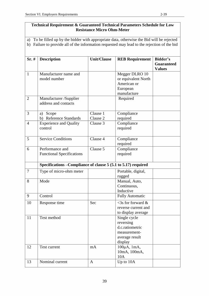
Technical Requirement & Guaranteed Technical Parameters Schedule for Low
Resistance Micro Ohm-Meter
a) To be filled up by the bidder with appropriate data, otherwise the Bid will be rejected
b) Failure to provide all of the information requested may lead to the rejection of the bid
Sr. # Description Unit/Clause REB Requirement Bidder’s
Guaranteed
Values
1 Manufacturer name and
model number
Megger DLRO 10
or equivalent North
American or
European
manufacture
2 Manufacturer /Supplier
address and contacts
Required
3 a) Scope
b) Reference Standards
Clause 1
Clause 2
Compliance
required
4 Experience and Quality
control
Clause 3 Compliance
required
5 Service Conditions Clause 4 Compliance
required
6 Performance and
Functional Specifications
Clause 5 Compliance
required
Specifications –Compliance of clause 5 (5.1 to 5.17) required
7 Type of micro-ohm meter Portable, digital,
rugged
8 Mode Manual, Auto,
Continuous,
Inductive
9 Control Fully Automatic
10 Response time Sec <3s for forward &
reverse current and
to display average
11 Test method Single cycle
reversing
d.c.ratiometric
measurement-
average result
display
12 Test current mA 100μA, 1mA,
10mA, 100mA,
10A
13 Nominal current A Up to 10A
Page 40
Section VI. Employers Requirements 2-40
40
14 Test current accuracy % ±10%
15 Test current stability Ppm <10 ppm per
second
16 Resolution Ω 0.1Ω
17 Resistance measurement Ω 0.1 Ω to 2000 Ω
(2k in 3Ωs)
18 Max. power limit W 250mW (to avoid
heating test
sample)
19 Visible warning of high
voltage at test terminal
Required
20 Maximum Lead Resistance Ω 100mΩ total for
10A operation
irrespective of
battery condition.
21 Voltmeter input impedance kΩ > 200kΩ
22 Hum rejection Less than 1%
23 Result storage download,
PC/Laptop connectivity &
USB
Required
24 Software CD Required
25 Display as given in Clause
5 (sub-clauses 5.12, 5.13,
5.14, 5.15)
LED 4-1/2Digit
26 Overload & short circuit
protection
Required
27 Guaranteed NiMH Battery
life
Years Rechargeable/5Yea
rs (Min.)/Via
external 90 V-260
V 50 Hz charger
28 Whether NiMH Battery
replaceable
Required
29 Degree of protection as per
IEC 60529 (IP64)
IP64
30 Rugged, impact proof &
durable carry case for
instrument and test leads
Compliance
required
31 Manufacturer's
recommended
cables/testing leads, clips
& connectors (as per
clause 5.9 & 5.10) -
without cables, leads, clips
& accessories instrument
Clause 5.9 &
5.10
Compliance
required
Page 41
Section VI. Employers Requirements 2-41
41
will not be accepted
32 Display Clause 6.1 Compliance
required
33 Carry Case Clause 7.1 Compliance
required
34 Type Test reports Clause 10.1 Compliance
required
35 Training to BREB staff Clause 9 Compliance
required
36 Model Required
37 Year of manufacture Required
38 Operating manual Clause 8.1 Required
39 Weight of instrument Kg Required
40 Size cm/inch Required
41 Submittal as per
specification
Clause 14 Required
42 Clause by Clause
conformanceofthis
technical specification
Clause 14 Required
Note:
a) Vendor shall provide clause by clause conformance of this technical specification
with the submittal duly signed and stamped
b) List of deviations and clauses to which exception are taken by the
bidder/vendor/supplier (add sheet, if necessary)
43 Name & signature of
authorized representative
with date
44 Official Seal/Stamp
Page 42
Section VI. Employers Requirements 2-42
42
Specification# 9
RURAL ELECTRIFICATION BOARD
PEOPLES REPUBLIC OF BANGLADESH
Hot Air Oven
Technical Specification
1. Scope
1.1 This specification covers minimum technical requirements for the supply of
“Hot Air Electric Oven” having electronic digital display and automatic time
control.
1.2 Bangladesh Rural Electrification Board (BREB) staff intends to use “Hot Air
Electric Oven” in their laboratory environment for carrying out Hot Set,
Shrinkage and other applicable tests on samples of Cross-linked Polyethylene
(XLPE) and Polyvinylchloride (PVC) materials at an elevated temperature in
accordance with IEEE and IEC standards.
1.3 Any departure from the provisions of this specification shall be disclosed at
the time of bidding under the title “deviation from specifications”.
1.4 This specification is property of BREB and subject to change or modification
without any notice.
2. Experience and Quality Control
2.1 The “Hot Air Electric Oven” shall be manufactured by a supplier that has an
experience of fabricating instruments of similar design and characteristics for a
period not less than five years and that holds ISO:9001-2015 Certification for
quality management.
3. Reference Standards
3.1 The “Hot Air Electric Oven” shall conform to the latest editions of the
standards applicable to their construction and application for Hot Set test,
Shrinkage test, Ageing test and other specified tests on XLPE insulation and
PVC sheath samples of power cables, including but not limited to those, and
their normative references from IEC, ISO, DIN and other applicable standards.
Power cable reference standards are as follows:
(a) IEC 60502-1 & 2: Power cables with extruded insulation and their
accessories for rated voltages from 1kV up to 30 kV, Part-1: Cables for
rated 1 kV (Um=1.2 kV) and 3 kV (Um=3.6 kV, Part-2: Cables for rated 6
kV (Um=7.2 kV) up to 30 kV (Um=36kV)
(b) IEC 60811-507 -2012: Hot set test for cross-linked materials
Page 43
Section VI. Employers Requirements 2-43
43
4. Service Conditions
4.1 The hot air electric oven shall be suitable under the local service conditions in
Bangladesh, which are as follows:
a) Altitude above mean sea level (MSL): 1,000 meters
b) Maximum summer peak ambient temperature: +45°C
c) Minimum outdoor winter temperature: 3°C
d) Average daily temperature: +35°C
e) Maximum yearly average temperature: +30°C
f) Relative humidity: 50% - 100%
g) Yearly average humidity: 80%
h) Pollution level: Moderate
i) Climate: Tropical, intense sun shine, heavy rain, maximum humidity
and temperature often occur both simultaneously
j) Storage temperature: -10°C - +70°C
k) Operating temperature: -10°C - +45°C
5. Performance Specifications and Constructional Features
5.1 The “Hot Air Electric Oven” shall meet or exceed the requirements of this
specification in all respects.
5.2 The hot air oven shall be an electrically powered device, which shall provide
dry air heat up and maintain temperature for hot set test, elongation and other
IEC 60811 specified tests on samples of cross-linked Polyethylene (XLPE)
and Polyvinylchloride (PVC) materials.
5.3 Oven inside the chamber shall have an arrangement for suspension of dumb-
bell shaped samples (prepared in accordance with IEC 60811-501) with
weights attached to lower grips exerted at a specified value for the material.
5.4 The oven shall operate in laboratory environment and maintain the desired
temperature for the preset time using thermostat control.
5.5 The oven shall be double walled insulation to keep and maintain energy. The
inner layer shall be poor conductor and outer layer shall be metallic. There
shall be air-circulating system for uniform distribution of heat.
5.6 In the control panel there shall be indicators for controls of temperature and
time.
5.7 The power supply shall be from main power 415/240 V source at 50 Hz.
5.8 The Oven shall have the following constructional specifications and features:
a) Portable, reliable, high accuracy and easy to use
b) Size: 24inch x 24inch x 24inch of inside chamber
c) Range: Ambient (Co)– to – 250C
o
d) Resolution: 1 Co
e) Double walled with in between adequate thermal insulation
Page 44
Section VI. Employers Requirements 2-44
44
f) With industrial grade and reliable air circulation system to maintain
uniform temperature inside the chamber
g) Digital temperature indicator with controller and auto-time controller
h) Provided with sensors for control
i) Inside chamber should be large enough and have suitable arrangements for
hanging samples
j) LCD Display and LED annunciations
k) Touch keys for operation menu
l) Alarms at start and stop of tests and in abnormal conditions like high
temperature limits
m) LED indications for: heating, timer, fan, Power NO/OFF, real time clock,
data logging, connectivity with PC and data management software
n) Electric oven to have electrical protection with circuit breaker and surge
diversion
5.9 In case of conflict or ambiguity, the vendor may propose a value with
corresponding reference standard without effecting the requirements of this
specification.
6. Operating Manual
6.1 A comprehensive operating manual-user guide shall be provided with the hot
air electric oven, which shall contain operational information, description of
oven parts, electrical circuits, size and weight, warnings signs, controls,
technical specifications, allowable temperature range and other useful
features.
7. Inspection Certificate
7.1 An inspection certificate shall be provided to verify conformance to the
applicable Standards and calibration.
7.2 Pre-shipment inspection shall not be required.
7.3 Material shall be inspected for conformance to quality, calibration and
constructional features on arrival in accordance with the technical
specification, before acceptance. Deficient material shall be rejected.
8. Marking
8.1 The hot air oven shall be marked with the following information:
a) Manufacturer’s name
b) Model, year of manufacture and identifying number
c) Manufacturer logo or trademark and brand name
d) Technical specifications and temperature range
e) Power requirements (Volts, Amps, Watts, Hz etc.)
Page 45
Section VI. Employers Requirements 2-45
45
9. Packaging and Shipping
9.1 Export packaging and shipping shall be adequate for sea transport and
handling up to delivery in Bangladesh
9.2 The material shall be sealed in plastic bags or other suitable moisture proof
materials and packed in sturdy cardboard carton in completely assembled
condition. Each box shall contain equipment and installation instructions.
9.3 The material shall be boxed or otherwise suitably protected against damage or
loss during shipment and to facilitate field hand storage. All openings shall be
effectively sealed with temporary closures to prevent entry of dust, dirt,
moisture and other foreign matter.
9.4 The cover of the main carton/bag shall carry the following information written
in English:
a) Description of material contained therein
b) Manufacturer’s catalog number
c) Manufacturer’s name
d) Description of material
e) Purchase order number
f) Gross weight in kg and size
g) Bar coding
9.5 Additional handling and shipping instructions shall be obtained from BREB as
applicable.
10. Warranty
10.1 The manufacturer /vendor shall warrant hot air electric oven supplied under
this specification to be free from defects in design, materials, or workmanship
for a period of one (1) years from the date of delivery, unless otherwise
specified in tender documents. During the period of such warranty, defective
units shall be replaced at manufacturer/vendor cost.
10.2 If no exceptions are taken to this specification and no list of deviations is
submitted, it shall be deemed that in every respect the offered equipment shall
be conforming to this specification. Purchaser’s interpretation of this
specification shall be accepted.
11. Technical Data, Drawings and Submittal
11.1 The Bidder shall clearly identify the manufacturer, type, and model number,
and provide catalog information such as lists of capabilities and drawings for
the proposed item demonstrating compliance with specification at the time of
bidding. Bidder shall not be allowed to make substitutions subsequent to
acceptance by BREB.
Page 46
Section VI. Employers Requirements 2-46
46
11.2 The supplier/manufacturer shall provide hard and soft copies of the technical
and other information, catalogues with the bid submittal as follows:
(a) Outline drawings of the oven showing the dimensions and physical
features of the hot air oven
(b) Guaranteed technical parameter schedule
(c) Guaranteed insensitivity of electronic parts from inside oven temperatures
(d) Certified Calibration test reports
(e) Packaging details
(f) Terms of manufacturer’s warranty.
(g) Manufacturer’s certificate attesting to 5 years of experience manufacturing
(h) Statement of country of origin for all items
(i) Copy of ISO: 9001-2015 Certification for the manufacturing plant
(j) Copies of test certificates evidencing completion of qualification and
conformance tests
(k) Statement of acceptance and compliance with these specifications or a list
and explanations for any deviations from or exceptions to these
specifications
(l) List of clients in last five years, which were supplied “Hot Air Electric
Oven” for laboratory use
Page 47
Section VI. Employers Requirements 2-47
47
Technical Requirements & Guaranteed Technical Parameters Schedule for Hot Air
Electric Oven
a) To be filled up by the bidder with appropriate data, otherwise the Bid will be rejected
b) Failure to provide all of the information requested may lead to the rejection of the bid
Sr. # Description Unit/Clause REB Requirement Bidder’s
Guarantee
d Values
1 Manufacturer name and
model number
Required
2 Manufacturer/ Supplier
address and contacts
Required
3 a) Scope
b) Experience and
Quality Control
Clause 1
Clause 2
4 a) Reference Standards
b) Service Conditions
Clause 3
Clause 4
Compliance required
5 Type of Hot Air Electric
Oven
Clause 5 Lab. Grade, portable,
electrically powered,
415/240V, 50Hz
6 Specified Size Clause 5 b 24inchx24inchx24inch
7 Control Clause 5 g Automatic
8 Range Clause 5 c Ambient Co-+250C
o
9 Resolution Clause 5.8 d 1 Co
10 Construction Clause 5.8 Compliance required
11 Air circulation Clause 5.8f Compliance required
12 Temperature Indicator Clause 5.8g Clause 5.8g; Required
13 Display & LED
indications
Clause 5.8 j &
m
Compliance required
14 Protection & safety Clause 5.8n Compliance required
15 Model Required
16 Year of manufacture Required
Page 48
Section VI. Employers Requirements 2-48
48
17 Operating manual Clause 6.1 Required
18 Weight of Oven Kg Required
19 Offered Size cm/Inch Required
20 Submittal as per
specification
Clause 11.1 Required
21 Clause by Clause
conformance of this
technical specification
Clause 11.1 Required
Note:
a) Vendor shall provide clause by clause conformance of this technical specification
with the submittal duly signed and stamped
b) List of deviations and clauses to which exception are taken by the
bidder/vendor/supplier (add sheet, if necessary)
22 Name & signature of
authorized representative
with date
23 Official Seal/Stamp
Page 49
Section VI. Employers Requirements 2-49
49
Specification# 12
RURAL ELECTRIFICATION BOARD
PEOPLES REPUBLIC OF BANGLADESH
Single-Phase and Three-Phase Energy Meters Testing and Calibration System
Technical Specification
1. Scope
1.1 This specification covers minimum technical requirements for design,
manufacture, testing, supply, installation and commissioning of a Single-Phase
and Three-Phase Energy Meters Testing and Calibration Equipment/System at
a laboratory site designated by Bangladesh Rural Electrification Board
(BREB).
1.2 The test equipment/system will be used for the acceptance, routine and other
specified testing of static and electromechanical single-phase and three-phase
energy meters up to accuracy class 0.05 and conforming to the relevant ANSI
and IEC standards (clause 2).
1.3 Any departure from the provisions of this specification shall be disclosed at
the time of bidding under the title “deviation from specifications”.
1.4 This specification is property of BREB and subject to change or modification
without any notice.
2. Reference Standards
2.1 Energy Meters Testing and Calibration Equipment shall conform to the latest
editions of the standards applicable to their design, construction, production
and for testing applications, including but not limited to those listed below,
and their normative references:
(a) ANSI C12.1-2014: Code for Electricity Metering
(b) ANSI C12.10-2011: Physical Aspects of Watt-hour Meters-Safety
Standard
(c) ANSI C12.20 -2010: For Electricity Meters - Accuracy Class 0.2 and 0.5
(d) IEEE C37.90.1-2012: Surge Withstand Capability Tests for Relays and
Relay System Associated with Electric Power Apparatus
(e) ANSI C12.18: Protocol specification for ANSI type 2 optical port
(f) IEEE C57.13: Instrument Transformers
(g) IEC 62052-11: Electricity metering equipment (a.c.)-General
requirements, tests and test conditions
(h) IEC 62053-21: Electricity metering equipment (a.c.)-Static meters for
active energy (Class 1 and 2)
(i) IEC 62053-23: Electricity metering equipment (a.c.)-Static meters for
reactive energy (Class 2 and 3)
Page 50
Section VI. Employers Requirements 2-50
50
3. Experience and Quality Control
3.1 Energy meters testing and calibration equipment shall be manufactured at a
plant that has fabricated equipment of similar ratings, design and
characteristics for a period not less than ten years and that holds ISO: 9001-
2015 Certification for quality management.
4. Service Conditions
4.1 Energy meters testing and calibration equipment shall be suitable for indoor
operations in a meter testing laboratory environment under the local service
conditions in Bangladesh, which are as follows:
a) Altitude above mean sea level (MSL): 1,000 meters
b) Maximum summer peak ambient temperature: +45°C
c) Minimum outdoor winter temperature: 3°C
d) Average daily temperature: +35°C
e) Maximum yearly average temperature: +30°C
f) Relative humidity: 50% - 100%
g) Yearly average humidity: 80%
h) Pollution level: Moderate
i) Climate: Tropical, intense sun shine, heavy rain, maximum humidity and
temperature often occur both simultaneously
j) Storage temperature: -10°C - +70°C
k) Operating temperature: -10°C - +45°C
5. Energy Meters in BREB System
5.1 Energy meters testing and calibration equipment shall be modular test system
to be used for the acceptance and routine testing of static and electro-
mechanical energy meters conforming to ANSI and IEC standards (clause 2)
as follows:
a) Single-Phase energy meters 10/60 A, 240/415 V, 50Hz, bottom
connected, A type Base
b) Three-phase four wire energy meters rated 10/100A, 240/415 V, 50Hz,
bottom connected, A type Base
c) Single-Phase energy meters, 200A, socket type
d) Three-Phase four wire, 15/100A, 240/415 V, 50Hz, self-contained,
without demand, socket type
e) Three-phase four wire, 15/100A, 240/415 V, 50Hz, self-contained,
with demand, socket type
f) Three-phase four wire, 15/100A, 240/415 V, 50Hz, self-contained,
without demand, transformer rated, socket type
5.2 System voltage: 240/415 V, 3 Phase Y, 50Hz
Page 51
Section VI. Employers Requirements 2-51
51
6. General
6.1 The offered test equipment shall be reliable, cost effective, low maintenance,
high accuracy, calibrated and meet or exceed the requirements of this
specification in all respects.
6.2 The test equipment shall be capable of performing all specified routine and
other tests within one system to fulfill the testing requirements of IEEE/ANSI
and IEC standards referred in clause 2 of this specification.
6.3 The test systems shall offer master PC and software for automated test
protocol using a well-designed sequence with minimal human intervention to
avoid humanly induced errors.
6.4 The energy meter testing and calibration equipment shall comprise of one
complete system for testing 3 single-phase, 3 three phase-energy meters and
shall have the minimum following components in general:
a) A transformer operated precise voltage, current and power source (self-
protected)
b) A static reference standard meter of specified accuracy class: 0.05
c) A powerful measuring electronics for error calculation
d) Pulse processing and comparator
e) Data communication and control
f) Energy meters mounting universal modular rack for 6 positions: 3
positions for mounting single phase energy meters and 3 positions for
mounting three phase energy meters to be tested from the same system
g) Meters connecting devices, cables, connectors and accessories
h) 6 number optical sensors for scanning both (i) mark on meter’s disk and
(ii) LED output of static meters
i) Window based Software package with licenses
j) All associated accessories
7. Design and Features
7.1 The supplier shall be responsible for providing fully functional testing bench
with all essential components, parts, instruments, racks, cables, connectors,
sensors, power supplies; software package, PC, printers etc. The energy
meters testing equipment with close loop capacity (for 3 meters) shall
comprise of, but not limited to those items listed below:
a) Precision Power Source: Three Phase transformer power source
3x300V/100VA and 3x120A/100VA. The power source shall be self-
protected against system over voltages, surges and harmonics. It shall be
highly stabilized, high accuracy and fully calibrated.
b) Reference Standard Meter: High accuracy and calibrated 3 Phase reference
standard 500V/120A, Class: 0.05
Page 52
Section VI. Employers Requirements 2-52
52
c) Fixed Handling System: Desk with metallic stand for mounting up to three
(3) number three phase and three (3) number single phase energy meters
with quick connection system
d) Power supply unit/modules for the precision electronically compensated
CTs needed for the system (described in this specification).
e) Complete Local Evaluation Unit: For evaluation of error of the tested
meter (for testing both dynamic & static meters with optical
communication head)
f) Precision electronically compensated 3 current transformers, three phase
common mode rejecter with current isolation, class 0.05
g) Software Package for electricity meter testing (Control software and data
Archiver) – License for testing 6 meters (3 single phase and 3 three phase),
user friendly Windows based program in English
h) Main Control and Evaluation Unit PC: Basic Control System (PC, LCD
Display, Windows) and Communication Controller
i) Microsoft Office -English language, Microsoft Office (for output protocol
creation) and test report generation
j) Laser Printer, latest A4 printer for output protocol printing
k) Memory to store and transfer data to laptop via interfacing communication
cable
8. Technical Specifications
8.1 Input:
a) Voltage: 240/415Volts +/-10%, 3 phase 4Wire
b) Frequency: 40-70Hz
c) Power rating: 3x300V / 100VA and 3x120A / 100VA
d) Display: system shall display details of output parameters
e) Warming time: maximum 10 Minutes
8.2 Output:
a) Voltage: 3 x 40 to 3x450 V continuously variable AC
b) Current: 3 x 1mA to 3 x100 A
c) Phase Angle: 0- 360o
d) Output Power: Suitable for 6 positions (3 for single phase energy
meters and 3 three phase energy meters to be tested from common
testing system but with respective applicable settings at a time)
8.3 Test Current Circuit:
a) Current ranges (A): 0.1A, 0.25 A, 0.5A-2.5A-5A-10A-20A-30A-50A-
100A-120A
b) Percentage load ranges: 0%, 2.5%, 5%, 10%, 20%, 30%, 50%, 100%,
120%
c) Current adjustment: 0-120% consecutively adjustable
d) Starting current selection switch settings: Selectable 0.25%, 0.5%, 0.75
%, 1%, 1.5%
e) Type of phase shifter: Network type/ Induction type
8.4 Power Factor:
a) Power factor range: 90o lag/ 90
o lead
b) Power factor quick selector setting: In steps of 30o
and in between
values continuously variable in each phase
c) Phase sequence: Phase sequence selector switch
8.5 Reference Standard Meter:
Page 53
Section VI. Employers Requirements 2-53
53
a) Voltage range: 0.5V-500V
b) Current range: 1 mA- 120A
c) Accuracy of energy measurement (Precision Class): 0.05%
d) Phase angle range: 0-360o, accuracy: 0.02
e) Frequency: 40-70Hz
f) Display: Built-in and details of parameters
g) Keypad: Built-in
h) Measured parameters: Power, Active Energy, Reactive Energy,
Apparent Voltage, Current/ Phase, Frequency, Distortion, Harmonic
content
8.6 Communication Port: RS 232 serial and cable
8.7 Mounting Rack:
a) Meter mounting rack details: Vendor shall specify in offer with detail
design
b) Number of measuring positions on rack: 3 single phase energy meters
and 3 three phase energy meters
c) Number of scanning heads: six (6)
d) Scanning head response time: Vendor shall specify
e) Number of individual error displays: six (6)
f) Pulse input cable: one for each position
8.8 Software and Accessories:
a) Vendor shall propose details of hardware and software (operating
system) and configuration of computer and control system
b) HP Laser jet printer (vendor shall propose the latest model)
c) Automatic and manual operation modes shall be provided
d) Software shall be capable of:
i) Defining details of each meter under test i.e serial number, type,
ratings, make etc.
ii) Defining test sequence
iii) Testing 10 similar type/rated meters having different meter
constants
iv) Displaying individual errors of the meters under test on the PC
v) Displaying the instantaneous parameters including vector diagram
measured by the standard meter
vi) Defining error tolerance
vii) Printing the test results of all tested meters
8.9 Scanning heads shall be able to detect colored marks on disc of
electromechanical meters and LED from static meters
8.10 Test bench shall be able to facilitate testing both bottom-connected “A Base”
meters and “Socket” type meters
8.11 Test bench shall have:
a) Overload and surge protection
b) Auto-range for current and voltage
c) Auto/manual test programmable by software
d) Test three-phase and single-phase meters
Page 54
Section VI. Employers Requirements 2-54
54
e) Suitable for 3 phase 4 wire system
f) Software Window based, results can be saved, searched and printed out
g) Database provides statistics, category, and information check, serial
numbers, and type of meter, data management, create and delete fields
h) Test equipment mounted on a panel in racks
i) Spare fuses (ten pieces), if used in the testing system shall be provided
with the equipment
8.12 In case of conflict or ambiguity, the vendor may propose a value with
corresponding reference standards in their respective submittal without
effecting the requirements of this specification.
9. Operating Manuals and Documentation
9.1 The energy meters testing and calibration system shall be provided with a set
of operation and maintenance manuals in English language.
9.2 The manuals shall contain detailed description of each component of the test
equipment; parts of it like reference standard, amplifier, measurement
software, power source, voltage and current amplifiers, error calculations,
programming test schemes, report generation and printing etc.
9.3 Schematic wiring diagram shall be part of the operating manual.
9.4 Dimensional drawings and floor layout plan shall be provided.
10. Installation, Testing and Commissioning
10.1 The supplier shall be responsible for Energy Meters Testing and Calibration
System installation, testing, commissioning at BREB proposed site and
handing over of equipment to the BREB designated representatives in fully
functional form.
10.2 The supplier shall provide in advance the physical layout plan and other
requirements for installation of the energy meters testing bench to BREB for
review and approval.
11. Training
11.1 The supplier shall provide training to BREB designated engineers and
technicians. The training shall be on the use of the system for testing and
calibration of single-phase and three-phase energy meters, use of software,
measurements, recording test data, data transfer and processing through
Windows based software, recording of error and accuracy to fulfill testing
requirements of ANSI and IEC reference standards.
11.2 The training shall comprise of a balanced combination of classroom training
and hands-on experience, and shall cover all aspects of equipment operation.
12. Tests
Page 55
Section VI. Employers Requirements 2-55
55
12.1 Type Test:
The manufacturer shall provide at the time of tender, certificates attesting to the fact
that that type tests have been carried out successfully on the test equipment. The
manufacturer shall also provide test certificates for conformance, safety and power
source protection against over voltage and surges. The type test certificates for
standard meter calibration shall be from an independent accredited testing laboratory.
12.2 Routine Tests:
The supplier shall subject the test equipment produced to routine tests.
12.3 Acceptance Tests:
Subsequent to completion of the routine testing by the manufacturer, and at the
Purchaser’s option, the manufacturer shall be requested to have factory acceptance
tests (FAT) on the meter testing and calibration system under delivery in the
presence of the Purchaser’s representatives. If testing and calibration system
fails the acceptance tests protocol, the offered equipment shall be rejected. The
FAT protocol shall be proposed by the supplier and approved by BREB.
13. Name Plate
13.1 The following information shall be given on the name plate of the Energy
Meters Testing Bench:
a) Manufacturer’s name
b) Model, year of manufacture and identifying number
c) Allowable ambient temperature range, safety warnings, power supply and
technical specifications
d) Reference Standards
e) Manufacturer logo or trademark and brand name
f) Weight and size of equipment
14. Packaging and Shipping
14.1 Export packaging and shipping shall be adequate for sea or air transport and
handling up to delivery site in Bangladesh.
14.2 The material shall be sealed in plastic bags or other suitable moisture proof
materials and packed in sturdy cardboard cartons in completely assembled
condition. Each box shall contain test equipment and installation instructions.
14.3 The material shall be skidded, crated, boxed or otherwise suitably protected
against damage or loss during shipment and to facilitate field hand storage.
All openings shall be effectively sealed with temporary closures to prevent
entry of dust, dirt, moisture and other foreign matter.
14.4 The cover of the main crate/carton shall carry the following information
written in English:
Page 56
Section VI. Employers Requirements 2-56
56
(a) Number of test instrument contained therein
(b) Manufacturer’s catalog number
(c) Description of the material
(d) Manufacturer’s name
(e) Purchase order number
(f) Gross weight in kg
(g) Bar code
14.5 Additional handling and shipping instructions shall be obtained from BREB as
applicable.
15. Warranty
15.1 The manufacturer/vendor shall warrant test equipment supplied under this
specification to be free from defects in design, materials, or workmanship for
a period of two (2) years from the date of delivery, unless otherwise specified
in tender documents. During the period of such warranty, defective units shall
be replaced at manufacturer/vendor cost.
15.2 If no exceptions are taken to this specification and no list of deviations is
submitted, it shall be deemed that in every respect the offered test set
conforms to this specification. Purchaser’s interpretation of this specification
shall be accepted.
16. Technical Data, Drawings and Submittal
16.1 The supplier/manufacturer shall provide hard and soft copies of technical data,
catalogues, testing procedure and other information in the bid submittal, as
follows:
(a) Outline drawings of the meter testing equipment showing the dimensions,
schematic drawings, catalogues, data sheets and physical features
(b) Guaranteed technical parameters schedule
(c) Certified calibration test reports
(d) Packaging details
(e) Terms of manufacturer’s warranty
(f) Manufacturer’s certificate attesting to 10 years of experience
manufacturing
(g) Statement of country of origin for all items
(h) Copy of ISO 9001-2015,certification for the manufacturing plant
(i) Copies of type test reports and certificates evidencing completion of
qualification tests from an accredited testing laboratory
(j) Statement of acceptance and compliance with these specifications or a list
and explanations for any deviations from or exceptions to these
specifications
(k) List of clients in last five years with their respective addresses, which were
supplied “Energy Meters Testing and Calibration System”
Page 57
Section VI. Employers Requirements 2-57
57
Technical Requirement & Guaranteed Technical Parameters Schedule for Single-
Phase and Three-Phase Energy Meters Testing and Calibration System
a) To be filled up by the bidder with appropriate data, otherwise the Bid will be
rejected
b) Failure to provide all of the information requested may lead to the rejection of the
bid
Sr.
#
Description Clause REB Requirement Bidder’s
Guarantee
d Values
1 Manufacturer
name and model
number
Applied Precision, ELMA-
6 or equivalent North
American or European
manufacturer
2 Manufacturer
/Supplier address
and contacts
Required
3 Scope and
Reference
Standards
1 & 2 Compliance Required
4 Experience,
Quality Control &
Service
Conditions
3 & 4 Compliance Required
5 "Energy Meter
Testing System"
to be suitable for
meters type in
BREB network
5 (sub-clauses
5.1 & 5.2)
Compliance Required
6 Testing system
“General
Specifications”
Clause 6 (sub-
clauses 6.1 to
6.4)
Compliance Required
7 Testing system
"Design and
Features”
Clause 7 (sub-
clauses 7.1 (a
to k))
Compliance Required
8 Testing equipment
components
7.1 a) Precision Power
Source: Three Phase
transformer power
source 3x300V/100VA
and 3x120A/100VA.
The power source shall
be self-protected
against system over
voltages, surges and
harmonics. It shall be
highly stabilized, high
accuracy and fully
Page 58
Section VI. Employers Requirements 2-58
58
calibrated.
b) Reference Standard
Meter: High accuracy
and calibrated 3 Phase
reference standard
500V/120A, Class:
0.05
c) Fixed Handling
System: Desk with
metallic stand for
mounting up to three
(3) number three phase
and three (3) number
single phase energy
meters with quick
connection system
d) Power supply
unit/modules for the
precision electronically
compensated CTs
needed for the system
(described in this
specification).
e) Complete Local
Evaluation Unit: For
evaluation of error of
the tested meter (for
testing both dynamic
& static meters with
optical communication
head)
f) Precision
electronically
compensated 3 current
transformers, three
phase common mode
rejecter with current
isolation, class 0.05
g) Software Package for
electricity meter
testing (Control
software and data
Archiver) – License for
testing 6 meters (3
single phase and 3
three phase), user
friendly Windows
based program in
English
h) Main Control and
Evaluation Unit PC:
Page 59
Section VI. Employers Requirements 2-59
59
Basic Control System
(PC, LCD Display,
Windows) and
Communication
Controller
i) Microsoft Office -
English language,
Microsoft Office (for
output protocol
creation) and test
report generation
j) Laser Printer, latest
A4 printer for output
protocol printing
k) Memory to store and
transfer data to laptop
via interfacing
communication cable
9 Technical
Specifications:
Input
8.1 a) Voltage: 240/415Volts
+/-10%, 3 phase 4Wire
b) Frequency: 40-70Hz
c) Power rating: 3x300V
/ 100VA and 3x120A /
100VA
d) Display: system shall
display details of
output parameters
e) Warming time: maximum 10 Minutes
10 Output 8.2 a) Voltage: 3 x 40 to
3x450 V continuously
variable AC
b) Current: 3 x 1mA to 3
x100 A
c) Phase Angle: 0- 360o
d) Output Power: Suitable for 6 positions
(3 for single phase
energy meters and 3
three phase energy
meters to be tested
from common testing
system but with
respective applicable
settings at a time)
Page 60
Section VI. Employers Requirements 2-60
60
11 Test Current
Circuit
8.3 e) Current ranges (A):
0.1A, 0.25 A, 0.5A-
2.5A-5A-10A-20A-
30A-50A-100A-120A
f) Percentage load
ranges: 0%, 2.5%,
5%, 10%, 20%, 30%,
50%, 100%, 120%
g) Current adjustment: 0-120% consecutively
adjustable
h) Starting current
selection switch
settings: Selectable
0.25%, 0.5%, 0.75 %,
1%, 1.5%
i) Type of phase shifter: Network type/
Induction type
12 Power Factor 8.4 a) Power factor range: 90
o lag/ 90
o lead
b) Power factor quick
selector setting: In
steps of 30o and in
between values
continuously variable
in each phase
c) Phase sequence: Phase sequence
selector switch
13 Reference
Standard Meter
8.5 a) Voltage range: 0.5V-
500V
b) Current range: 1 mA-
120A
c) Accuracy of energy
measurement
(Precision Class):
0.05%
d) Phase angle range: 0-
360o, accuracy: 0.02
e) Frequency: 40-70Hz
f) Display: Built-in and
details of parameters
g) Keypad: Built-in
h) Measured
parameters: Power,
Active Energy,
Reactive Energy,
Apparent Voltage,
Current/ Phase,
Page 61
Section VI. Employers Requirements 2-61
61
Frequency, Distortion,
Harmonic content
14 Communication
Port - RS 232
serial and cables
8.6 Compliance Required
15 Meter Mounting
Rack
8.7 (a to f) Compliance Required
16 Software and
Accessories as per
clause 8.8 (a to d)
8.8 Compliance Required
17 Scanning Heads 8.9 Compliance Required
18 Test Bench
suitable for Meter
Mounting
arrangements
9.10 Compliance Required
19 Testing System
requirements
8.11 a) Overload and surge
protection
b) Auto-range for current
and voltage
c) Auto/manual test
programmable by
software
d) Test three-phase and
single-phase meters
e) Suitable for 3 phase 4
wire system
f) Software Window
based, results can be
saved, searched and
printed out
g) Database provides
statistics, category, and
information check,
serial numbers, and
type of meter, data
management, create
and delete fields
h) Test equipment
mounted on a panel in
racks
i) Spare fuses (ten
pieces), if used in the
testing system shall be
provided with the
equipment
20 Installation,
Testing &
Commissioning
10 Compliance Required
Page 62
Section VI. Employers Requirements 2-62
62
21 Training to BREB
Staff
11 Compliance Required
22 Type Tests,
testing and test
reports
12 Compliance Required
23 Model
Required
24 Year of
manufacture
Required
25 Operating manual
and
documentations
9 Compliance Required
26 Weight of
equipment
Kg
Required
27 Size and
installation layout
cm/Inch/m Required
28 Submittal as per
specification
16 Required
29 Clause by Clause
conformance of
this technical
specification
16 Required
Note:
a) Vendor shall provide clause by clause conformance of this technical
specification with the submittal duly signed and stamped
b) List of deviations and clauses to which exception are taken by the
bidder/vendor/supplier (add sheet, if necessary)
30 Name & signature
of authorized
representative
with date
31 Official
Seal/Stamp
Page 63
Section VI. Employers Requirements 2-63
63
Specification# 13
RURAL ELECTRIFICATION BOARD
PEOPLES REPUBLIC OF BANGLADESH
Distribution Transformers Testing System
Technical Specifications
1. Scope
1.1 This specification covers minimum technical requirements for the design,
manufacture, testing, supply, and commissioning of “Distribution
Transformers Testing System” for performing specified routine and other tests
on new, reclaimed and used single phase distribution transformers of
Bangladesh Rural Electrification Board (BREB).
1.2 The “Distribution Transformers Testing System” means equipment,
instruments, accessories, cables, connectors, probes, sensors, data acquisition
software, tests management and reports generation software, operator interface,
control console, computer, safety devices etc. which are essentially required to
perform all specified routine and other tests (clause 6.8) on BREB distribution
transformers to fulfill testing requirements of IEEE standards (clause 2).
Lightning impulse tests and equipment is not part of this specification.
1.3 Any departure from the provisions of this specification shall be disclosed at the
time of bidding under the title “deviation from specifications”.
1.4 This specification is property of BREB and subject to change or modification
without any notice.
2. Reference Standards
2.1 Distribution transformers testing equipment and instruments shall conform to the
latest editions of the standards applicable to their design, construction,
production and testing applications, including but not limited to those listed
below, and their normative references:
a) IEEE C57.12.90-2005: Test Code for Liquid-Immersed Distribution,
Power, and Regulating Transformers
b) ASTM D3487-09: Specification for Mineral Insulating Oil Used in
Electrical Apparatus
c) IEC 60076: Power Transformers General
d) IEC 60051-2: Special Requirements for Ammeter and Voltmeter
e) IEC 60051-3: Special Requirements for Wattmeter and VAR-meter
f) REB Publication: 290 -1988 Overhead Type Distribution Transformers
Page 64
Section VI. Employers Requirements 2-64
64
3. Experience and Quality Control
3.1 Distribution transformers testing equipment and instruments shall be manufactured
at a plant that has fabricated such instruments of similar ratings, design and
characteristics for a period not less than ten years and that holds ISO:9001-2015
Certification for quality management.
4. Service Conditions
4.1 The distribution transformers testing equipment and instruments shall be suitable for
performing tests in a transformer testing laboratory under the local service conditions
in Bangladesh, which are as follows:
a) Altitude above mean sea level (MSL): 1,000 meters
b) Maximum summer peak ambient temperature: +45°C
c) Minimum outdoor winter temperature: 3°C
d) Average daily temperature: +35°C
e) Maximum yearly average temperature: +30°C
f) Relative humidity: 50% - 100%
g) Yearly average humidity: 80%
h) Pollution level: Moderate
i) Climate: Tropical, intense sun shine, heavy rain, maximum humidity
and temperature often occur both simultaneously
j) Storage temperature: -10°C - +70°C
k) Operating temperature: -10°C - +45°C
5. System Configuration and Transformers
5.1 System parameters of local BREB 11kV power distribution network are as
follows:
a) System primary voltage (U): 11kV r.m.s
b) System highest voltage (Um): 12kV r.m.s
c) Nominal voltage-phase to neutral (Uo): 6.35kV r.m.s
5.2 Distribution transformers in BREB overhead line network are single-phase,
oil-immersed, self-cooled and conforming to IEEE C57.12.90-2005 standard.
Voltage and kVA ratings of transformers are as follows:
a) Nominal voltage ratings:
i) H.V. winding: 6.35kV (phase to neutral)
ii) L.V. winding: 240V
b) Basic Insulation levels (BIL) of primary and secondary windings:
i) H.V. winding: 95kV
ii) L.V. winding: 30V
c) System frequency (f): 50 Hz
d) Transformers kVA ratings: 5kVA up to 100kVA, 167kVA, 250kVA
and 333kVA (BREB Publication: 290 -1988)
Page 65
Section VI. Employers Requirements 2-65
65
e) Percent impedance of transformers: Not exceeding 2-1/2% at rated
kVA
f) Single-phase transformers with ratings of 200 kVA or less have
additive polarity and transformers with ratings over 200 kVA have
subtractive polarity.
5.3 Provision for testing three-phase distribution transformers conforming to
IEEE/ANSI and IEC standards shall also be kept. Voltage and kVA ratings of
three phase transformers are as follows:
i) H.V. winding: 33kV
ii) L.V. winding: 415V and 240V phase to neutral
iii) Transformer rating: 100, 200kVA
6. Performance and Functional Specifications
6.1 The offered distribution transformers testing equipment shall be reliable, cost
effective, low maintenance, high accuracy, calibrated and meet or exceed the
requirements of this specification in all respects.
6.2 The transformers testing equipment and instruments shall be capable of
performing all specified routine and other tests within one system to fulfill the
testing requirements of IEEE/ANSI and IEC standards referred in clause 2 of
this specification.
6.3 The testing system shall have master PC and software for automated test
protocol using a well-designed sequence with minimal human intervention to
avoid humanly induced errors.
6.4 The offered testing system shall contain all essential instruments, associated
accessories, cables, probes, connectors, sensors, extension boxes, safety
devices and interlocks, power supplies (with surge protection), adopters,
operator interface and control desk etc.
6.5 The frequency converter shall be compact, clean and silent power supply.
6.6 The testing system shall perform tests within one system and free from
adjustment at test frequencies from 40Hz to 200Hz.
6.7 The distribution transformers testing equipment shall have the following
salient features:
a) Centralized controlling system
b) Highest accuracy, calibrated and certified measurement and testing
system
c) Perform tests on distribution transformers (see clause 6.8)
d) Accurate loss measurement
e) Highly reliable and accurate frequency converter
f) Software with automated test sequences-auto test procedures
g) Automated calculations of all results with test report generation and
printing system
Page 66
Section VI. Employers Requirements 2-66
66
6.8 The distribution transformer testing system shall perform tests specified in
IEEE/ANSI and IEC standards as follows:
a) Winding resistance measurements
b) Polarity and phase-relation test
c) Transformer ratio test
d) No load losses and excitation current at rated voltage and current
e) Load losses and impedance voltage
f) Temperature-rise test
g) Dielectric tests
i) Applied-voltage test
ii) Induced-voltage test
iii) Insulation resistance test
6.9 Vendor shall provide with the technical submittal, hard and soft copies of the
data sheets, technical specifications, schematic wiring diagrams and catalogue
for each instrument contained in the test systems.
7. Instrumentation
7.1 Vendor shall offer complete set of high quality, cost effective and high
accuracy electronic/digital instruments (voltmeter, ammeter, wattmeter,
thermometer etc.) with LED displays to cover specified tests (clause 6.8) along
with associated accessories, cables, connectors, sensors, probes etc.
8. Design Features
8.1 The distribution transformers testing equipment shall have the following
design features:
a) Control power key switch with indicator
b) Main and control power circuit breakers
c) Duty cycle and power rating: vendor proposed
d) Motor-driven tap switch with indicators
e) Motorized control of output voltage
f) Adjustable rate of rise
g) Raise and lower pushbuttons with OFF Zero indicator
h) Test mode selector switch with indicator
i) Automatic/Semi-automatic/Manual ranging of wattmeter and voltmeter
with direct readout
j) Hold feature to freeze all meter displays for recording
k) RMS and average responding voltmeters
l) 3-watmeter method of power measurement
m) Voltage sensing leads
n) Fork truck and overhead lifting provisions, where applicable
o) Operator interface and control console mounted on desk
Page 67
Section VI. Employers Requirements 2-67
67
9. Safety
9.1 The distribution transformers testing equipment shall have main safety
features as follows:
a) Zero-start interlock
b) Protective devices on measurement system and on critical components
c) Foot switch where required
d) Provision of external security circuit with indicator
e) Emergency OFF switch
f) External interlock provision
g) Recessed jack for output leads
h) Flashing red warning light
10. Data Acquisition Software
10.1 The data acquisition software shall have following features:
a) Computer aided data acquisition system record all test data
b) Data acquisition system perform corrections
c) Calculate corrected losses, efficiency, regulation, percent impedance
etc.
d) Generate reports to avoid human errors and print out of results.
e) User friendly and Windows based flexible to build transformers testing
data base for future reference and generating test reports
f) Offer sequence wise specified tests and guide the operators through
programmed test procedures
g) Indicate connection mistakes
11. Operator Interface Display
11.1 The distribution transformers testing system shall have operator interface
display and control console. It shall have computer control functions by
operator to selecting tests, connecting wires to the test specimens and initiating
a test. Operator shall be able to transfer data to PC for acquisition, processing
and storage.
12. Conflict
12.1 In case of conflict or ambiguity, the vendor may propose a value; substitute a
clause with corresponding reference standards in their respective offer but
without effecting the requirements of this specification.
Page 68
Section VI. Employers Requirements 2-68
68
12.2 Vendor is encouraged to study distribution transformers testing system
suitable for BREB requirement before preparing submittal. However, the
offered systems shall fulfill tests requirement of IEEE and IEC standards
(clause 2).
13. Operating Manual and Documentation
13.1 The distribution transformers testing system shall be provided with a set of
service manuals for operation and maintenance purpose in English language.
13.2 Operating manuals shall also contain:
a) Detailed description of each instrument of the test equipment
b) Detailed description of test sequence and use of software
c) Schematic wiring diagrams
d) Dimensional drawings and floor layout plan, where applicable
14. Installation, Testing and Commissioning
14.1 The supplier shall be responsible for installation, testing, calibration and
commissioning of test equipment including programming of the software at
BREB approved site.
14.2 Upon successful testing and commissioning, the testing equipment shall be
handed over to the BREB nominated representatives in fully functional form.
14.3 The supplier shall provide in advance the physical layout plan for installation of
distribution transformers testing equipment to BREB for approval.
15. Training
15.1 The supplier shall provide training to BREB engineers and technicians. The
training shall be on the use of the equipment, instruments, connections and
measurements, data acquisition and processing through Windows based
software, recording of test results in accordance with IEEE standards (clause
2) and generating test reports.
15.2 The training shall comprise of a balanced combination of classroom training
and hands-on experience, and shall cover all aspects of equipment operation.
16. Tests
16.1 Type Test:
The manufacturer shall provide at the time of tender, certificates attesting to
the fact that that type tests have been carried out successfully on all
instruments/components of the test equipment. The manufacturer shall also
provide test certificates for conformance, safety and power source protection
Page 69
Section VI. Employers Requirements 2-69
69
against over voltage and surges. The type test certificates for the equipment
shall be from an independent accredited testing laboratory.
16.2 Routine Tests:
The manufacturer shall subject the equipment and instruments contained in the
transformers testing system, to the specified routine tests at their plant before
offering the material for acceptance tests.
16.3 Acceptance Tests:
Subsequent to completion of the routine testing by the manufacturer, and at the
Purchaser’s option, the manufacturer shall be requested to have factory
acceptance tests (FAT) on the distribution transformer test equipment under
delivery in the presence of the purchaser’s representatives. If any equipment or
instruments fail the acceptance tests (given in the approved acceptance tests
protocol), the offered equipment or instruments shall be rejected. The
acceptance tests protocol shall be proposed by the supplier and approved by
the purchaser.
17. Name Plate
17.1 The following information shall be given on the name plate of each
instrument of the testing equipment:
a) Manufacturer’s name
b) Model, year of manufacture and identifying number
c) Allowable ambient temperature range, safety warnings, power supply and
technical specifications
d) Reference Standards
e) Manufacturer logo or trademark and brand name
f) Weight and size of equipment
18. Packaging and Shipping
18.1 Export packaging and shipping shall be adequate for sea or air transport and
handling up to delivery site in Bangladesh.
18.2 The material shall be sealed in plastic bags or other suitable moisture proof
materials and packed in sturdy cardboard cartons in completely assembled
condition. Each box shall contain test equipment and installation instructions.
18.3 The material shall be skidded, crated, boxed or otherwise suitably protected
against damage or loss during shipment and to facilitate storage. All openings
shall be effectively sealed with temporary closures to prevent entry of dust,
dirt, moisture and other foreign matter.
18.4 The cover of the main crate shall carry the following information written in
English:
a) Number of test instrument contained therein
Page 70
Section VI. Employers Requirements 2-70
70
b) Manufacturer’s catalog number
c) Description of the material
d) Manufacturer’s name
e) Purchase order number
f) Gross weight in kg
g) Bar code
18.5 Additional handling and shipping instructions shall be obtained from BREB
as applicable.
19. Warranty
19.1 The manufacturer/vendor shall warrant test equipment supplied under this
specification to be free from defects in design, materials, or workmanship for a
period of two (2) years from the date of delivery, unless otherwise specified in
tender documents. During the period of such warranty, defective items shall be
replaced at manufacturer/vendor cost.
19.2 If no exceptions are taken to this specification and no list of deviations is
submitted, it shall be deemed that in every respect the offered test set conforms
to this specification. Purchaser’s interpretation of this specification shall be
accepted.
20. Technical Data, Drawings and Submittal
20.1 The supplier/manufacturer shall provide hard and soft copies of technical
data, drawings, catalogues, installation, testing and commission plan, testing
procedures and documentation with the bid submittal, as follows:
a) Outline drawings of the transformer test equipment/instrumentsshowing
the dimensions and physical features
b) Layout plan of equipment and wiring diagrams.
c) DTTS system list of equipment (BOQs).
d) Guaranteed technical parameters schedule
e) Description of items, data sheets of each instrument contained in the test
systems and details of cables, accessories, probes, sensors etc.
f) Certified testing and calibration test reports
g) Packaging details
h) Terms of manufacturer’s warranty
i) Manufacturer’s certificate attesting to 10 years of experience in
manufacturing
j) Statement of country of origin for all items
k) Copy of ISO:9001-2015 Certification for the manufacturing plant
l) Copies of type test certificates evidencing completion of qualification tests
from an accredited testing laboratory
m) Statement of acceptance and compliance with these specifications or a list
and explanations for any deviations from or exceptions to these
specifications
n) List of clients in last five years with their addresses, which were supplied
distribution transformers testing system/equipment
Page 71
Section VI. Employers Requirements 2-71
71
Technical Requirements & Guaranteed Technical Parameters Schedule for
Distribution Transformers Testing System (DTTS)
a) To be filled up by the bidder with appropriate data, otherwise the Bid will be
rejected
b) Failure to provide all of the information requested may lead to the rejection of
the bid
Sr.
#
Description Clause REB Requirement Bidder’s
Guarantee
d Values
1 Manufacturer name
and model number
Haefely-Hipotronics
DTTS or equivalent
North American or
European
manufacture
2 Manufacturer/Supplie
r’s address and
contacts
Required
3 Scope and Reference
Standards
1 & 2 Compliance Required
4 Experience, Quality
Control and Service
Conditions
3 & 4 Compliance Required
5 BREB Distribution
System configuration
and transformers in
network
5 Compliance Required
6 Performance and
Functional
Specifications of
distribution
transformers testing
equipment
6 (sub-
clauses from
6.1 to 6.9)
Compliance Required
7 Test equipment
salient features
6.7 a) Centralized
controlling system
b) Highest accuracy,
calibrated and
certified
measurement and
testing system
c) Perform tests on
distribution
transformers (see
clause 6.8)
d) Accurate loss
measurement
e) Highly reliable
and accurate
Page 72
Section VI. Employers Requirements 2-72
72
frequency
converter
f) Software with
automated test
sequences-auto
test procedures
g) Automated
calculations of all
results with test
report generation
and printing
system
8 DTTS shall perform
the tests as specified
in IEEE/ANSI and
IEC standards
6.8 a) Winding
resistance
measurements
b) Polarity and
phase-relation test
c) Transformer ratio
test
d) No load losses and
excitation current
at rated voltage
and current
e) Load losses and
impedance voltage
test
f) Temperature-rise
test
g) Dielectric tests
i) Applied-
voltage test
ii) Induced-
voltage test
iii) Instrument
resistance test
9 Instrumentation 7.1 Compliance Required
10 DTTS Design
Features
8.1 (a to o) a) Control power key
switch with
indicator
b) Main and control
power circuit
breakers
c) Duty cycle and
power rating:
vendor proposed
d) Motor-driven tap
switch with
indicators
Page 73
Section VI. Employers Requirements 2-73
73
e) Motorized control
of output voltage
f) Adjustable rate of
rise
g) Raise and lower
pushbuttons with
OFF Zero
indicator
h) Test mode
selector switch
with indicator
i) Automatic/Semi-
automatic/Manual
ranging of
wattmeter and
voltmeter with
direct readout
j) Hold feature to
freeze all meter
displays for
recording
k) RMS and average
responding
voltmeters
l) 3-watmeter
method of power
measurement
m) Voltage sensing
leads
n) Fork truck and
overhead lifting
provisions, where
applicable
o) Operator interface
and control
console mounted
on desk
11 Protection and Safety
Features
9.1 (a to h) a) Zero-start
interlock
b) Protective devices
on measurement
system and on
critical
components
c) Foot switch where
required
d) Provision of
external security
circuit with
Page 74
Section VI. Employers Requirements 2-74
74
indicator
e) Emergency OFF
switch
f) External interlock
provision
g) Recessed jack for
output leads
h) Flashing red
warning light
12 Data Acquisition
Software
10.1 (a to g) Compliance Required
13 Operator's Interface
Display
11.1 Compliance Required
14 Operating manual &
documentation
131 & 13.2 Compliance Required
15 Installation, Testing
& Commissioning
14 Compliance Required
16 Training to BREB
Staff
15 Compliance Required
17 Type Tests, testing &
test reports
16.1 Compliance Required
18 Year of manufacture Required
19 Weight of DTTS
equipment
Kg Required
20 Size and equipment
layout
cm/Inch/m Required
21 Submittal as per
specification
20 Required
22 Clause by Clause
conformance of this
technical
specification
20 Required
Note:
a) Vendor shall provide clause by clause conformance of this technical
specification with the submittal duly signed and stamped
b) List of deviations and clauses to which exception are taken by the
bidder/vendor/supplier (add sheet, if necessary)
Page 75
Section VI. Employers Requirements 2-75
75
23 Name & signature of
authorized
representative with
date
24 Official Seal/Stamp
Page 76
Section VI. Employers Requirements 2 -76
76
Specification# 14
RURAL ELECTRIFICATION BOARD
PEOPLES REPUBLIC OF BANGLADESH
Power Transformers Testing System
Technical Specification
1. Scope
1.1 This specification covers minimum technical requirements for the design,
manufacture, testing, supply and commissioning of “Power Transformers
Testing System” for performing specified routine and other tests on new,
reclaimed and used power transformers of Bangladesh Rural Electrification
Board (BREB).
1.2 The “Power Transformers Testing System” means equipment, instruments,
accessories, cables, connectors, probes, sensors, data acquisition software,
tests management and report generation software, operator interface, control
console, computer, safety devices etc. which are essentially required to
perform specified routine and other tests (clause 7.8) on BREB transformers to
fulfill tests requirements of IEEE and IEC standards (clause 2). Lightning
impulse tests and equipment is not part of this specification.
1.3 Any departure from the provisions of this specification shall be disclosed at
the time of bidding under the title “deviation from specifications”.
1.4 This specification is property of BREB and subject to change or modification
without any notice.
2. Reference Standards
2.1 Power Transformers testing equipment shall conform to the latest editions of
the standards applicable to their design, construction, production and for
testing applications including but not limited to those listed below, and their
normative references:
a) IEEE C57.12.90-2005: Test Code for Liquid-Immersed Distribution,
Power, and Regulating Transformers
b) ASTM D3487-09: Specification for Mineral Insulating Oil Used in
Electrical Apparatus
c) IEC 60076: Power Transformers General
d) IEC 60051-2: Special Requirements for Ammeter and Voltmeter
e) IEC 60051-3: Special Requirements for Wattmeter and VAR-meter
f) IEC 60296: Mineral Insulating Oil for Transformers and Switchgears
g) IEC 60076-7: Loading guide for oil-immersed power transformers
h) IEC 60214: Tests on OLTC
Page 77
Section VI. Employers Requirements 2 -77
77
3. Experience and Quality Control
3.1 Power Transformers testing equipment shall be manufactured at a plant that
has fabricated such testing instruments of similar ratings, design and
characteristics for a period not less than ten years and that holds ISO:9001-
2015,certification for quality management.
4. Service Conditions
4.1 The power transformers testing equipment and instruments shall be suitable
for performing tests in a transformer testing laboratory under the local service
conditions in Bangladesh, which are as follows:
a) Altitude above mean sea level (MSL): 1,000 meters
b) Maximum summer peak ambient temperature: +45°C
c) Minimum outdoor winter temperature: 3°C
d) Average daily temperature: +35°C
e) Maximum yearly average temperature: +30°C
f) Relative humidity: 50% - 100%
g) Yearly average humidity: 80%
h) Pollution level: Moderate
i) Climate: Tropical, intense sun shine, heavy rain, maximum humidity
and temperature often occur both simultaneously
j) Storage temperature: -10°C - +70°C
k) Operating temperature: -10°C - +45°C
5. System Configuration
5.1 System parameters of local BREB 33/11kV overhead line power distribution
network are as follows:
a) Primary Voltage (U): 33kV r.m.s
b) System highest voltage (Um): 36kV r.m.s
c) Secondary Voltage: 11kV r.m.s
d) System frequency (f): 50 Hz
e) 3 Phase short circuit capacity: 31.5kA for 3s
f) BIL: 170kVp for 33 kV and 95kVp for 11 kV
5.2 System parameters of local 11kV (phase to phase)/6.35kV (phase to neutral)
overhead line distribution network are as follows:
a) System primary voltage (U): 11kV r.m.s
b) System highest voltage (Um): 12kV r.m.s
c) Nominal voltage-phase to neutral (UO): 6.35kV
d) Secondary Voltage: 240/415V
e) BIL: 95kVp
Page 78
Section VI. Employers Requirements 2 -78
78
6. Power Transformers in BREB System
6.1 There are three types of power transformers operating in the existing 33/11 kV
power distribution network, which are intended to be tested, and are described
in clauses 6.2, 6.3 and 6.4.
6.2 Single-phase power transformers, outdoor-type, oil immersed, cooling ONAN
conforming to IEEE C57.12.90-2005 standard (REB Publication: 915 -1988)
with technical parameters as follows:
a) Voltage rating:
i) H.V. winding: 33kV
ii) L.V. winding: 11kV/6.35kV (phase to ground) grounded Y
b) Basic Insulation level (BIL) of primary and secondary windings:
i) H.V. winding: 200kV
ii) L.V. winding: 110kV
c) System frequency (f): 50 Hz
d) Three units rated 1667kVA are connected in a bank of 5 MVA and
three units rated 3333kVA are connected in a bank of 10MVA
e) Percent impedance of transformers: 6%
6.3 Three phase power transformers outdoor-type, oil immersed, cooling ONAN
conforming to IEEE C57.12.90-2005 standard (BREB Publication: 915-
1988)with technical parameters as follows:
a) Voltage rating:
i) H.V. winding: 33kV
ii) L.V. winding: 11kV/6.35kV (phase to neutral) in Y
configuration
b) Basic Insulation level (BIL) of primary and secondary windings:
i) H.V. winding: 200kV
ii) L.V. winding: 110kV
c) Rated 5MVA and 10MVA, Δ-Y, DYn1, without OLTC
d) Percent impedance of transformers: 6%
6.4 Three-phase power transformers, oil-immersed, ONAN/ONAF conforming to
IEC 60076 standard with technical parameters as follows:
a) Voltage rating:
i) H.V. winding: 33kV
ii) L.V. winding: 11kV/6.35kV (phase to neutral) in Y
configuration
b) Basic Insulation level (BIL) of primary and secondary windings:
i) H.V. winding: 170kV
ii) L.V. winding: 75kV
c) Rated 10/14MVA and 20/28MVA, Δ-Y, DYn1, with on-load tap
changer (OLTC), cooling type ONAN and ONAF
d) Percent impedance of transformers: For 10 MVA - 8% and for
20MVA-10%
Page 79
Section VI. Employers Requirements 2 -79
79
7. Performance and Functional Specifications
7.1 The offered power transformer testing equipment shall be reliable, cost
effective, low maintenance, high accuracy, calibrated and meet or exceed the
requirements of this specification in all respects.
7.2 The transformers testing equipment and instruments shall be capable of
performing all specified routine and other tests within one system to fulfill the
testing requirements of IEEE/ANSI and IEC standards referred in clause 2 of
this specification.
7.3 The test systems shall offer master PC and software for automated test
protocol using a well-designed sequence with minimal human intervention to
avoid humanly induced errors.
7.4 The offered systems shall include all associated accessories, cables, probes,
connectors, sensors, extension boxes, interlocks, safety devices, power
supplies (with surge diverter), adopters, operator interface and control desk
etc.
7.5 The frequency converter shall be compact, clean and silent power supply.
7.6 The testing system shall perform tests within one system and free from
adjustment at test frequencies from 40Hz to 200Hz.
7.7 The power transformers testing equipment shall have the following salient
features:
a) Centralized controlling system
b) Highest accuracy, calibrated and certified measurement and testing
system
c) Tests transformers (see clause 6)
d) Accurate loss measurement
e) Highly reliable and accurate frequency converter
f) Software with automated test sequences-auto test procedures
g) Automated calculations of all results with test report generation and
printing system
7.8 The power transformers testing system shall perform tests specified in
IEEE/ANSI and IEC standards (clause 2), as follows:
a) Winding resistance measurements
b) Polarity and phase-relation tests
c) Ratio tests
d) No load (iron) losses and excitation current
e) Load (copper) losses and impedance voltage
f) Induced-voltage test
g) Applied-voltage test
h) Insulation resistance test
i) C and tan delta of insulation
j) Insulation power factor test
k) Partial discharge testing
l) Temperature-rise test and cooling curve
Page 80
Section VI. Employers Requirements 2 -80
80
7.9 Vendor shall provide with the technical submittal, hard and soft copies of the
data sheets, technical specifications and catalogue of all instrument contained
in the power transformer test systems.
8. Instrumentation
8.1 Vendor shall offer complete set of high quality, cost effective and high
accuracy electronic/digital instruments (voltmeter, ammeter, wattmeter,
thermometer etc.) with LED displays to cover all specified tests along with
accessories, cables, connectors, sensors, probes etc.
9. Design Features
9.1 The power transformers testing equipment shall have the design features as
follows:
a) Control power key switch with indicator
b) Main and control power circuit breakers
c) Duty cycle: vendor proposed
d) Motor-driven tap switch with indicators
e) Motorized control of output voltage
f) Adjustable rate of rise
g) Raise and lower pushbuttons with OFF Zero indicator
h) Test mode selector switch with indicator
i) Automatic/Semi-automatic/Manual ranging of wattmeter and voltmeter
with direct readout
j) Hold feature to freeze all meter displays for recording
k) RMS and average responding voltmeters
l) 3-watmeter method of power measurement
m) Voltage sensing leads
n) Fork truck and overhead lifting provisions
o) Operator interface and control console mounted on desk
10. Safety
10.1 The power transformers testing equipment shall have main safety features as
follows:
a) Zero-start interlock
b) Protective devices on measurement system, and critical components
c) Foot switch where required
d) Provision of external security circuit with indicator
e) Emergency OFF switch
f) External interlock provision
g) Recessed jack for output leads
Page 81
Section VI. Employers Requirements 2 -81
81
11. Data Acquisition Software
11.1 The data acquisition software shall have following features:
a) Computer aided data acquisition system record all test data
b) Data acquisition system perform corrections
c) Calculate corrected losses, efficiency, regulation, percent impedance
etc.
d) Generate reports to avoid human errors and print out of results.
e) User friendly and Windows based flexible to build transformers testing
data base for future reference and generating test reports
f) Offer sequence wise specified tests and guide the operators through
programmed test procedures
g) Indicate connection mistakes
12. Operator Interface Display
12.1 The power transformers testing system shall have operator interface display
and control console. It shall have the ability for computer control functions by
operator to selecting tests, connecting wires to the test specimens and initiating
a test. Operator shall be able to transfer data to PC for acquisition, processing
and storage.
13. Conflict
13.1 In case of conflict or ambiguity, the vendor may propose a value; substitute a
clause with corresponding reference standard in their respective offer, but
without effecting the requirements of this specification.
13.2 Vendor is encouraged to study power transformers testing system suitable for
BREB requirement before preparing submittal. However, the offered system
shall fulfill testing requirement of IEEE standard (clause 2).
14. Operating Manual and Documentation
14.1 The power transformers testing system shall be provided with a set of service
manuals for operation and maintenance purpose in English language.
14.2 Manuals shall also contain:
a) Detailed description of each instrument
b) Detailed description of test sequence and use of software
c) Schematic wiring diagrams
d) Dimensional drawings and floor layout plan
Page 82
Section VI. Employers Requirements 2 -82
82
15. Installation, Testing and Commissioning
15.1 The supplier shall be responsible for installation, testing, calibration and
commissioning of testing equipment including programming of the software at
BREB approved site.
15.2 Upon successful testing and commissioning, the testing equipment shall be
handed over to the BREB nominated representatives in fully functional form.
15.3 The supplier shall provide in advance the physical layout plan for installation
of power transformers testing equipment to BREB for approval.
16. Training
16.1 The supplier shall provide training to BREB engineers and technicians. The
training shall be on the use of the testing equipment, instruments, connections
and measurements, data acquisition and processing through Windows based
software, recording of test results in accordance with IEEE and IEC standards
(clause 2) and generating test reports.
16.2 The training shall comprise of a balanced combination of classroom training
and hands-on experience, and shall cover all aspects of equipment operation.
17. Test
17.1 Type Test:
The manufacturer shall provide at the time of tender, certificates attesting to
the fact that that type tests have been carried out successfully on all
instruments/components of the test equipment. The manufacturer shall also
provide test certificates for conformance, safety and power source protection
against over voltage and surges. The type test certificates for the equipment
shall be from an independent accredited testing laboratory.
17.2 Routine Tests:
The manufacturer shall subject the equipment/instruments contained in the
power transformers test systems, to the specified routine tests at their plant
before offering the material for acceptance tests.
17.3 Acceptance Tests:
Subsequent to completion of the routine testing by the manufacturer, and at the
Purchaser’s option, the manufacturer shall be requested to have factory
acceptance tests (FAT) on the power transformers testing equipment under
delivery in the presence of the purchaser’s representatives. If any equipment or
instrument fails the acceptance tests (given in the approved acceptance tests
protocol), the offered equipment or instrument shall be rejected. The
acceptance tests protocol shall be proposed by the supplier and approved by
the purchaser.
Page 83
Section VI. Employers Requirements 2 -83
83
18. Name Plate
18.1 The following information shall be given on the name plate of each instrument
of the test system:
a) Manufacturer’s name
b) Model, year of manufacture and identifying number
c) Allowable ambient temperature range, safety warnings, power supply,
accuracy and technical specifications
d) Reference standards
e) Manufacturer logo or trademark and brand name
f) Weight and size of equipment
19. Packaging and Shipping
19.1 Export packaging and shipping shall be adequate for sea or air transport and
handling up to delivery site in Bangladesh.
19.2 The material shall be sealed in plastic bags or other suitable moisture proof
materials and packed in sturdy cardboard cartons in completely assembled
condition. Each box shall contain test equipment and installation instructions.
19.3 The material shall be skidded, crated, boxed or otherwise suitably protected
against damage or loss during shipment and to facilitate storage. All openings
shall be effectively sealed with temporary closures to prevent entry of dust,
dirt, moisture and other foreign matter.
19.4 The cover of the main crate or container shall carry the following information
written in English:
a) Number of test instruments or equipment contained therein
b) Manufacturer’s catalog number
c) Description of the material
d) Manufacturer’s name
e) Purchase order number
f) Gross weight in kg
g) Bar code
19.5 Additional handling and shipping instructions shall be obtained from REB as
applicable.
20. Warranty
20.1 The manufacturer/vendor shall warrant testing equipment supplied under this
specification to be free from defects in design, materials, or workmanship for a
period of two (2) years from the date of delivery, unless otherwise specified in
tender documents. During the period of such warranty, defective items shall be
replaced at manufacturer/vendor cost.
Page 84
Section VI. Employers Requirements 2 -84
84
20.2 If no exceptions are taken to this specification and no list of deviations is
submitted, it shall be deemed that in every respect the offered test set conforms
to this specification. Purchaser’s interpretation of this specification shall be
accepted.
21. Technical Data, Drawings and Submittal
21.1 The supplier/manufacturer shall provide hard and soft copies of technical data,
drawings, catalogues, installation, testing and commission plan, testing
procedure and documentation in the bid submittal, as follows:
a) Outline drawings of the power transformers testing
equipment/instrumentsshowing the dimensions and physical features
b) Physical layout plan of equipment and schematic wiring diagrams
c) PTTS system list of equipment (BOQs).
d) Guaranteed technical parameters schedule
e) Technical data sheets of items and instruments contained in the power
transformers testing systems (PTTS)
f) Certified testing and calibration test reports of all items
g) Packaging details
h) Terms of manufacturer’s warranty
i) Manufacturer’s certificate attesting to 10 years of experience in
manufacturing
j) Statement of country of origin for all items
k) Copy of ISO:9001 Certifications for the manufacturing plant
l) Copies of type test reports and certificates evidencing completion of
qualification tests from an accredited testing laboratory
m) Statement of acceptance and compliance with these specifications or a list
and explanations for any deviations from or exceptions to these
specifications
n) List of clients in last five years with their addresses, which were supplied
power transformers testing system (PTTS) and equipment
Page 85
Section VI. Employers Requirements 2 -85
85
Technical Requirements & Guaranteed Technical Parameters Schedule for Power
Transformers Testing System (PTTS)
a) To be filled up by the bidder with appropriate data, otherwise the Bid will be rejected
b) Failure to provide all of the information requested may lead to the rejection of the bid
Sr.
#
Description Clause REB Requirement Bidder’s
Guaranteed
Values
1 Manufacturer Name
and model number
Haefely-Hipotronics
PTTS or equivalent North
American or European
manufacture
2 Manufacturer/Supplier
address and contacts
Required
3 Scope & Reference
Standards
1 & 2 Compliance Required
4 Experience & Quality
Control
3.1 Compliance Required
5 Service conditions 4.1 Compliance Required
6 BREB System
configuration
5 (sub-clauses
5.1 & 5.2)
Compliance Required
7 Testing of Power
Transformers in
BREB system
6 (sub-clauses:
6.1, 6.2, 6.3 &
6.4)
Compliance Required
8 PTTS Performance
and Functional
Specifications
7 (Sub-clauses:
7.1, 7.2,7.3, 7.4,
7.5, 7.6, 7.7, 7.8
& 7.9)
Compliance Required
9 PTTS test equipment
salient features
7.7 a) Centralized
controlling system
b) Highest accuracy,
calibrated and
certified measurement
and testing system
c) Tests transformers
(see clause 6)
d) Accurate loss
measurement
e) Highly reliable and
accurate frequency
converter
f) Software with
automated test
Page 86
Section VI. Employers Requirements 2 -86
86
sequences-auto test
procedures
g) Automated
calculations of all
results with test report
generation and
printing system
10 PTTS shall perform
the tests
7.8 a) Winding resistance
measurements
b) Polarity and phase-
relation tests
c) Ratio tests
d) No load (iron) losses
and excitation current
e) Load (copper) losses
and impedance
voltage
f) Induced-voltage test
g) Applied-voltage test
h) Insulation resistance
test
i) C and tan delta of
insulation
j) Insulation power
factor test
k) Partial discharge
testing
l) Temperature-rise test
and cooling curve
11 PTTS
Instrumentations
8.1 Compliance Required
12 PPTS Design Features 9.1 (a to g) a) Control power key
switch with indicator
b) Main and control
power circuit breakers
c) Duty cycle: vendor
proposed
d) Motor-driven tap
switch with indicators
e) Motorized control of
output voltage
f) Adjustable rate of rise
g) Raise and lower
pushbuttons with OFF
Zero indicator
h) Test mode selector
switch with indicator
i) Automatic/Semi-
automatic/Manual
Page 87
Section VI. Employers Requirements 2 -87
87
ranging of wattmeter
and voltmeter with
direct readout
j) Hold feature to freeze
all meter displays for
recording
k) RMS and average
responding voltmeters
l) 3-watmeter method of
power measurement
m) Voltage sensing leads
n) Fork truck and
overhead lifting
provisions
o) Operator interface and
control console
mounted on desk
13 PTTS Safety Features 10.1 (a to g) a) Zero-start interlock
b) Protective devices on
measurement system,
and critical
components
c) Foot switch where
required
d) Provision of external
security circuit with
indicator
e) Emergency OFF
switch
f) External interlock
provision
g) Recessed jack for
output leads
14 PTTS Data
Acquisition Software
11.1 (a to g) a) Computer aided data
acquisition system
record all test data
b) Data acquisition
system perform
corrections
c) Calculate corrected
losses, efficiency,
regulation, percent
impedance etc.
d) Generate reports to
avoid human errors
and print out of
results.
e) User friendly and
Windows based
Page 88
Section VI. Employers Requirements 2 -88
88
flexible to build
transformers testing
data base for future
reference and
generating test reports
f) Offer sequence wise
specified tests and
guide the operators
through programmed
test procedures
g) Indicate connection
mistakes
15 PTTS Operator
Interface Display
12.1 Compliance Required
16 Operating manual &
documentation
14.1 & 14.2 Compliance Required
17 Installation (lay-out
plan), Testing &
Commissioning
15.1, 15.2 &
15.3
Compliance Required
18 Training of BREB
Staff
16.1 & 16.2 Compliance Required
19 Type Tests, testing &
submission of type
test reports
17 Compliance Required
20 Year of manufacture
of equipment
&instruments
18 Required
21 Weight of PTTS
system equipment
Kg Required
22 Sizes of equipment cm/Inch/m Required
23 Submittal as per
specification
21 Required
24 Clause by Clause
conformance of this
technical specification
21 Required
Note:
a) Vendor shall provide clause by clause conformance of this technical specification
with the submittal duly signed and stamped
b) List of deviations and clauses to which exception are taken by the
bidder/vendor/supplier (add sheet, if necessary)
25 Name & signature of
authorized
representative with
date
Page 89
Section VI. Employers Requirements 2 -89
89
26 Official Seal/Stamp
Page 90
Section VI. Employers Requirements 2-90
90
Specification# 16
RURAL ELECTRIFICATION BOARD
PEOPLES REPUBLIC OF BANGLADESH
Field Testing Equipment/Set for:
a) Direct Energy Meter
b) CT Operated Energy Meter
c) CT/PT Operated Energy Meter
d) Instrument Transformer (CT & PT)
Technical Specification
1. Scope
1.1 This specification covers minimum technical requirements for design,
manufacture, testing and supply of “Field Testing Equipment/Set” for in
service energy meters and instrument transformers of Bangladesh Rural
Electrification Board (BREB).
1.2 The field test equipment or system shall fulfill specified testing requirements
for energy meters and instrument transformers (CT and CT/PT) existing in the
BREB distribution network. The test equipment shall be supplied with all
associated accessories, cables and connectors; connection boxes, adapters, data
management and analysis software; and data transfer to laptop/PC etc.
1.3 Any departure from the provisions of this specification shall be disclosed at
the time of bidding under the title “deviation from specifications”.
1.4 This specification is property of BREB and subject to change or modification
without any notice.
2. Reference Standards
2.1 Field Testing Set for testing energy meters and instrument transformers shall
conform to the latest edition of the standards applicable to their construction
and applications for testing, including but not limited to those listed below,
and their normative references:
(a) ANSI C12.1- 2014: Code for Electricity Metering
(b) ANSI C12.10- 2011: Physical Aspects of Watt-hour Meters-Safety
Standard
(c) ANSI C12.20 -2010: For Electricity Meters - Accuracy Class 0.2 and 0.5
(d) IEEE C37.90.1-2012: Surge Withstand Capability Tests for Relays and
Relay System Associated with Electric Power Apparatus
(e) ANSI C12.18: Protocol specification for ANSI type 2 optical port
(f) IEEE C57.13: Instrument Transformers
(g) IEC 62052-11: Electricity metering equipment (a.c.)-General
requirements, tests and test conditions
(h) IEC 62053-21: Electricity metering equipment (a.c.)-Static meters for
active energy (Class 1 and 2)
Page 91
Section VI. Employers Requirements 2-91
91
(i) IEC 62053-23: Electricity metering equipment (a.c.)-Static meters for
reactive energy (Class 2 and 3)
3. Experience and Quality Control
3.1 The test equipment shall be manufactured in a plant that has fabricated
instruments of similar ratings, design and characteristics for a period not less
than ten years and that holds ISO:9001-2015 Certification for quality
management.
4. Service Conditions
4.1 The testing equipment shall be suitable for indoor and outdoor field testing
under the local service conditions in Bangladesh, which are as follows:
a) Altitude above mean sea level (MSL): 1,000 meters
b) Maximum summer peak ambient temperature: +45°C
c) Minimum outdoor winter temperature: 3°C
d) Average daily temperature: +35°C
e) Maximum yearly average temperature: +30°C
f) Relative humidity: 50% - 100%
g) Yearly average humidity: 80%
h) Pollution level: Moderate
i) Climate: Tropical, intense sun shine, heavy rain, maximum humidity
and temperature often occur both simultaneously
j) Storage temperature: -10°C - +70°C
k) Operating temperature: -10°C - +45°C
5. Energy Meters in BREB System:
5.1 Energy meters in BREB system are both static and electro-mechanical type
conforming to ANSI standards, both socket and bottom connected type, with
current and voltage ratings as follows:
a) Single-Phase energy meters 10/60A, 240/415V, 50Hz, bottom
connected, A type Base
b) Three-phase energy meters rated 10/100A, 240/415V, 50Hz, bottom
connected, A type base
c) Single-Phase energy meters, 200A, socket type
d) Three-Phase four wire, 15/100A, 240/415V, 50Hz, self-contained,
without demand, socket type
e) Three-phase four wire, 15/100A, 240/415V, 50Hz, self-contained, with
demand, socket type
f) Three-phase four wire, 15/100A, 240/415V, 50Hz, self-contained,
without demand, transformer rated, socket type
g) CT operated 5/10A, 240/415 V, 50Hz meters
h) CT/PT operated meters
Page 92
Section VI. Employers Requirements 2-92
92
5.2 System Voltage: 240V single phase and 240/415 three phase four wire,
frequency: 50Hz
6. Performance, Technical Specifications and Features
6.1 The precision energy meter and instrument transformers testing system shall
be capable of performing complete diagnostic and accuracy tests on in-service
energy meters and associated instrument transformers in the BREB network
for the following functions:
a) Measurement of Active, Reactive and Apparent power and their
energies
b) Error measurement of 3 inputs simultaneously
c) Display of vector diagram for analysis of the mains conditions
d) Harmonic measurement
e) Burden measurement of current and potential transformers
f) Ratio tests of current and potential transformers (CT/PT)
g) Indicate wiring errors in CT and PT connections
6.2 The equipment shall be provided with the error compensated Clip-on precision
CTs up to 100 A, Clip-on precision CTs up to 1000 A, a set of current cables
for measurements up to 120A and scanning head with clamp device.
6.3 The equipment shall have surge and overvoltage protection.
6.4 The testing equipment shall have the following functional features:
a) Voltage Range: 0.04V - 480 V, 50 Hz (+/- 20%)
b) Current Range: 1 mA - 120A
c) Power Consumption: approximately 40VA
d) External magnetic influence: Equipment shall be protected and
negligible
e) 6 current inputs to measure simultaneously primary and secondary
currents in CT operated metering
f) Exchangeable memory for measurement results and customer data
g) Interface for data transfer to PC/Laptop
6.5 Current measurements (Amps) for direct meters shall have:
a) Current range: 1mA to 120A
b) Display Range: 1.0000mA to 120.0000A
c) Range:
i) 1mA to 40mA
ii) 40mA to 120mA
iii) 120mA to 400mA
iv) 400mA to 1.2A
v) 1.2A to 4A
vi) 4A to 12A
vii) 12A to 40A
viii) 40A to 120A
Page 93
Section VI. Employers Requirements 2-93
93
d) Measurement errors: Error ≤ ± 0.05% of measured value (40mA to
120A) and Error ≤ ± 0.05% (1 mA to 40 mA of the measurement range
final value)
6.6 Electronically compensated Clip-on CTs shall have:
a) Current range: 50 mA to 100A
b) Display range: 50.00 mA to 100.00A
c) Range:
i) 50mA to 800mA
ii) 800mA to 4A
iii) 20A to 100A
d) Measurement errors: Error ≤ ± 0.02% (0.5A to 100A of measured
value plus error of clip-on CTs) and for Clip-on CTs 1000A Error: ≤ ±
0.01% from 2A to 1000A of measured value plus error of CTs
6.7 Voltage measurements (U) shall be as follows:
a) Voltage range: 0.04 V to 480 V
b) Display range: 0.04000 V to 480.000 V
c) Range:
i) 0.04V to 0.4V
ii) 0.4V to 5V
iii) 5V to 60V
iv) 60V to 120V
v) 120V to 240V
vi) 240V to 480V
d) Measurement errors: Error ≤ ± 0.05% of measured value (30V to
480V) Error ≤ ± 0.05% - 0.04V to 5V (of the corresponding
measurement range final value)
6.8 Power Measurements (P, S, Q): Power measurement per phase on range 30 to
480 V and the accuracy of the power shall be related to apparent power
6.9 Error limits direct (40 mA to 120 A) shall be as follows:
i) Active power (P): Error ≤ ± 0.05%
ii) Reactive power (Q): Error ≤ ± 0.05%
iii) Apparent power (S): Error ≤ ± 0.05%
iv) Long term drift (PQS): Error ≤ ± 0.05% Year
6.10 Measurement errors with electronically compensated clip-on CTs (50mA to
100A) shall be as follows:
i) Active, Reactive: Error ≤ ± 0.02% (50 mA -100A)
ii) Apparent power (P, Q, S): Of the value final value Error ≤
± 0.5% (50 mA-499 of the measurement range final value)
iii) Display range: 6 digits for each measuring point
6.11 Power factor measurement (PF=P/S) shall be as follows:
i) Measurement error direct: Error ≤ ± 0.05% of the
measurement range final value
Page 94
Section VI. Employers Requirements 2-94
94
ii) Measurement error with electronically compensated clip-on
CT’s: Error ≤ ± 0.20% of the measurement final range
value
iii) Display range: - 1.00000 to +1.00000
6.12 Error calculation (E) shall be as follows:
a) Constant: 1 ... 1’000’000 Imp/ kWh (kvarh, kVAh)
1 ... 1’000’000 Imp/ Wh (varh, VAh)
1 ... 10’000 Imp/ Ws (Vars, VAs)
or 0.001 ... 100 Wh/Imp
b) Display range: - 100.000% ... +100.000%
6.13 Phase angle display resolution shall be: 0.10
6.14 Input frequency shall be: max. 200kHz
6.15 Degree of protection shall be: IP 40 (instrument open) and IP 68 (instrument
closed)
6.16 Memory to store and transfer data to laptop/PC via interfacing communication
cable
7. Instrument Transformers (CT & PT) Testing
7.1 Primary testing shall be carried out with error compensated clip-on CTs for
current up to 100 A, 1000 A. Secondary testing shall be conducted directly or
by using clip-on CTs 100 A for:
a) Instrument transformer (CT and PT) ratio
b) Instrument transformer (CT and PT) errors
c) Phase angles between primary and secondary
d) Burden measurements on secondary side of CT and PT
e) Load tests in assembled state for current and potential Burdens:
i) Operation burden and nominal burden
ii) Burden factor and impedance
f) CT demagnetization
Page 95
Section VI. Employers Requirements 2-95
95
7.2 The database shall be configured for predefined meters, CT and CT/PT data of
the measuring test points and set-up automatic test sequence.
7.3 Automatic measurement through test sequence shall be possible. Read-out of
stored data from the instrument shall have built-in memory and presentation
for processing the information.
8. Software Features
8.1 The instrument shall have all important electrical test parameters displayed
and shall make it possible to test simultaneously three electricity meters with
varying constant. Instrument shall be able to test in parallel using scanning
heads and emitting contact outputs. Software shall enable user to automatically
start predefined test sequence.
8.2 The instrument shall have analytical features for determining the signal form
and network power quality.
8.3 The vector diagrams of current and voltage shall be available and instrument
shall indicate wiring errors in CT and PT connections.
8.4 Energy meter and instrument transformers testing equipment shall have
software package designed to read test data from instrument, as well as
displaying and processing results on a PC/Laptop.
8.5 Software shall have an additional database with meter and test sequence
definition enabling the user to prepare and standardize measurements.
9. Carry Case
9.1 A rugged and impact proof durable protective carry case shall be provided for
holding instrument, set of leads, clips and manual. The protective cover shall
be dust, moisture and waterproof.
10. Operating Manual
10.1 The instrument shall be provided with the operating manual-user’s guide in
English language. User’s guide shall contain detailed description of the test
system, parts of it and operational procedure with pictures including
connection and wiring schemes and technical specifications.
11. Training and Safe Use
11.1 The supplier shall conduct training to REB engineers and technicians on the
application of test system. User shall be given training on safe application of
the instrument during measurements and use of software, test measurements,
data transfer and processing on software, field testing, recording errors in
metering and instrument transformers (CTs and PTs) including other functions
and features.
Page 96
Section VI. Employers Requirements 2-96
96
11.2 The training shall comprise of a balanced combination of classroom training
and hands-on experience, and shall cover all aspects of equipment operation.
12. Tests
12.1 Type Test:
The manufacturer shall provide at the time of tender, certificates attesting to
the fact that that type tests have been carried out successfully on the test
equipment. The manufacturer shall also provide conformance, safety, accuracy
and calibration certificates.
12.2 Routine Tests:
The test equipment produced shall be subjected to routine tests.
12.3 Acceptance Tests:
Subsequent to completion of the routine testing by the manufacturer, and at the
Purchaser’s option, the manufacturer may be requested to repeat acceptance
tests on test equipment in the presence of the Purchaser. If test equipment fails
the acceptance tests, the offered unit shall be rejected.
13. Name Plate
13.1 The following information shall be given on the name plate of the Insulation
Resistance Tester:
a) Manufacturer’s name
b) Model, year of manufacture and identifying number
c) Allowable ambient temperature range, safety warnings and technical
specifications
d) Reference standards
e) Manufacturer logo
f) Weight and size of equipment
Page 97
Section VI. Employers Requirements 2-97
97
14. Packaging and Shipping
14.1 Export packaging and shipping shall be adequate for sea transport and
handling up to delivery site in Bangladesh.
14.2 The material shall be sealed in plastic bags or other suitable moisture proof
materials and packed in sturdy cardboard cartons in completely assembled
condition. Each box shall contain test equipment and installation instructions.
14.3 The material shall be skidded, crated, boxed or otherwise suitably protected
against damage or loss during shipment and to facilitate field hand storage.
All openings shall be effectively sealed with temporary closures to prevent
entry of dust, dirt, moisture and other foreign matter.
14.4 The cover of the main crate/carton shall carry the following information
written in English:
h) Number of test instrument contained therein
i) Manufacturer’s catalog number
j) Description of the material
k) Manufacturer’s name
l) Purchase order number
m) Gross weight in kg
14.5 Additional handling and shipping instructions shall be obtained from BREB as
applicable.
15. Warranty
15.1 The manufacturer/vendor shall warrant test equipment supplied under this
specification to be free from defects in design, materials, or workmanship for a
period of two (2) years from the date of delivery, unless otherwise specified in
tender documents. During the period of such warranty, defective units shall be
repaired or replaced at manufacturer/vendor cost.
15.2 If no exceptions are taken to this specification and no list of deviations is
submitted, it shall be deemed that in every respect the offered test set conforms
to this specification. Purchaser’s interpretation of this specification shall be
accepted.
16. Technical Data, Drawings and Submittal
16.1 The supplier/manufacturer shall provide hard and soft copies of technical data
and other information with the bid submittal as follows:
a) Outline drawings of the portable field test equipment showing dimensions,
wiring diagrams for different testing schemes, catalogues, testing methods
for different applied/testing schemes, software applications and physical
features
b) Field Test System list of items (BOQs).
c) Guaranteed Technical Parameter schedules
Page 98
Section VI. Employers Requirements 2-98
98
d) Certified calibration test reports
e) Packaging details
f) Terms of manufacturer’s warranty
g) Manufacturer’s certificate attesting to 10 years of experience in
manufacturing
h) Statement of country of origin for all items
i) Copy of ISO:9001-2015 Certification for the manufacturing plant
j) Copies of type test reports and certificates evidencing completion of
qualification tests from an accredited testing laboratory
k) Statement of acceptance and compliance with these specifications or a list
and explanations for any deviations from or exceptions to these
specifications
l) List of clients in last five years with their addresses, which were supplied
field test set/equipment for testing energy meters and instrument
transformers
Page 99
Section VI. Employers Requirements 2-99
99
Technical Requirements & Guaranteed Technical Parameters Schedule Field
Testing Equipment for Energy Meters and Instrument Transformers:
Direct Energy Meter
CT Operated Energy Meter
CT/PT Operated Energy Meter
Instrument Transformer (CT & PT)
a) To be filled up by the bidder with appropriate data, otherwise the Bid will be rejected
b) Failure to provide all of the information requested may lead to the rejection of the bid
Sr. # Description Clause REB Requirement Bidder’s
Guaranteed
Values
1 Manufacturer name
and model number
MTE CALPORT 300
or equivalent North
American or European
manufacture
2 Manufacturer/Suppli
er address and
contacts
Required
3 Scope Clause1 Compliance Required
4 Reference Standards Clause 2.1 Compliance Required
5 Experience &
Quality Control
Clause 3.1 Compliance Required
6 Service conditions Clause 4.1 Compliance Required
7 Suitability of Field
Test Equipment for
BREB energy meters
in the network
Clause 5.1 (a
to h)
Compliance Required
8 System Voltage Clause 5.2 240V & 240/415V (+/-
10%), 50Hz
9 Field Test Set
Performance,
Technical
Specifications &
Functional Features
Clause 6 (6.1
to 6.16)
Compliance Required
Page 100
Section VI. Employers Requirements 2-100
100
10 Tests Equipment to
perform Tests
Clause 6.1 a) Measurement of
Active, Reactive
and Apparent power
and their energies
b) Error measurement
of 3 inputs
simultaneously
c) Display of vector
diagram for analysis
of the mains
conditions
d) Harmonic
measurement
e) Burden
measurement of
current and
potential
transformers
f) Ratio tests of
current and
potential
transformers
(CT/PT)
g) Indicate wiring
errors in CT and PT
connections
11 Test Set to be
provided with
equipment
Clause 6.2 Error compensated
Clip-on precision
CTs up to 100 A
Clip-on precision
CTs up to 1000 A,
Set of current cables
for measurements
up to 120A
Scanning head with
clamp device.
12 Test Set Protection Clause 6.3 Surge & Over-Voltage
Protection
13 Test Equipment
Functional Features
Clause 6.4 a) Voltage Range:
Voltage Range:
0.04V - 480 V, 50
Hz (+/- 20%)
b) Current Range: 1
mA - 120A
c) Power
Consumption:
approximately
40VA
Page 101
Section VI. Employers Requirements 2-101
101
d) External magnetic
influence:
Equipment shall be
protected and
negligible
e) 6 current inputs to
measure
simultaneously
primary and
secondary currents
in CT operated
metering
f) Exchangeable
memory for
measurement results
and customer data
g) Interface for data
transfer to
PC/Laptop
14 Amps range for
Direct Meters
Clause 6.5 a) Current range: 1mA to 120A
b) Display Range: 1.0000mA to
120.0000A
c) Range:
1mA to 40mA
40mA to
120mA
120mA to
400mA
400mA to 1.2A
1.2A to 4A
4A to 12A
12A to 40A
40A to 120A
15 Amps Measurements
Error limits
Clause 6.5 d Error ≤ ± 0.05% of
measured value
(40mA to 120A)
Error ≤ ± 0.05% (1
mA to 40 mA of the
measurement range
final value)
16 Electronically
compensated Clip-on
CTs Range
Clause 6.6 a) Current range: 50
mA to 100A
b) Display range:
50.00 mA to
100.00A
Page 102
Section VI. Employers Requirements 2-102
102
c) Range:
o 50mA to
800mA
o 800mA to 4A
o 20A to 100A
17 Measurement Error
Limits Clip-on CTs
Clause 6.6 d Error ≤ ± 0.02% (0.5A
to 100A of measured
value plus error of clip-
on CTs) and
for Clip-on CTs 1000A
of measured value plus
error of CTs
18 Voltage (U)
measurement Range
Clause 6.7 a, b,
c
a) Voltage range: 0.04
V to 480 V
b) Display range:
0.04000 V to
480.000 V
c) Range:
o 0.04V to 0.4V
o 0.4V to 5V
o 5V to 60V
o 60V to 120V
o 120V to 240V
o 240V to 480V
19 Voltage (U)
measurement Errors
limits
Clause 6.7 d o Error ≤ ± 0.05% of
measured value
(30V to 480V)
o Error ≤ ± 0.05% -
0.04V to 5V (of the
corresponding
measurement range
final value)
20 P, S, Q /Phase Range Clause 6.8 Power measurement per
phase on range 30 to
480 V and the accuracy
of the power shall be
related to apparent
power
21 P, S, Q Error limits
(40mA to 120A)
Clause 6.9 a) Active power (P):
Error ≤ ± 0.05%
b) Reactive power (Q):
Error ≤ ± 0.05%
c) Apparent power (S):
Error ≤ ± 0.05%
d) Long term drift
Page 103
Section VI. Employers Requirements 2-103
103
(PQS): Error ≤ ±
0.05% Year
22 Measurement error
limits with
electronically
compensated Clip-on
CTs (50mA to 100A)
Clause 6.10 a) Active, Reactive:
Error ≤ ± 0.02% (50
mA -100A)
b) Apparent power (P,
Q, S): Of the value
final value Error ≤ ±
0.5% (50 mA-499
of the measurement
range final value)
c) Display range: 6
digits for each
measuring point
23 Power Factor (P/S)
measurement
Clause 6.11 Measurement error
direct: Error ≤ ±
0.05% of the
measurement range
final value
Measurement error
with electronically
compensated clip-
on CT’s: Error ≤ ±
0.20% of the
measurement final
range value
Display range: -
1.00000 to
+1.00000
24 Error calculation (E) Clause 6.12 a) Constant: 1 ...
1’000’000 Imp/
kWh (kvarh, kVAh)
1 ... 1’000’000 Imp/
Wh (varh, VAh)
1 ... 10’000 Imp/
Ws (Vars, VAs)
or 0.001 ... 100
Wh/Imp
b) Display range: 100.000% ...
+100.000%
25 Phase angle display
resolution
Clause 6.13 0.10
Page 104
Section VI. Employers Requirements 2-104
104
26 Input Frequency Clause 6.14 200kHz
27 Degree of Protection Clause 6.15 IP 40 (IEC 60529)
28 Data storage & Data
transfer
Clause 6.16 Compliance Required
29 Instrument
Transformers (CT &
PT) Testing (Primary
testing with Clip-on
CTs (100A-1000A),
Secondary Testing
directly or with Clip-
On CTs (100A)
Clause 7.1, 7.2
& 7.3
a) Instrument
transformer (CT and
PT) ratio
b) Instrument
transformer (CT and
PT) errors
c) Phase angles
between primary
and secondary
d) Burden
measurements on
secondary side of
CT and PT
e) Load tests in
assembled state for
current and
potential Burdens:
o Operation
burden and
nominal burden
o Burden factor
and impedance
f) CT demagnetization
30 Software Features Clause 8.1,
8.2, 8.3, 8.4 &
8.5
Compliance Required
31 Carry case Clause 9.1 Compliance Required
32 Operating Manual Clause 10 Compliance Required
33 Training to BREB
Staff
Clause 11 Compliance Required
34 Type Tests, testing &
submission of test
reports
Clause 12 Compliance Required
35 Year of manufacture Required
36 Weight of Test
Equipment
Kg Required
37 Sizes cm/Inch Required
38 Submittal as per
specification
Clause 16 Required
Page 105
Section VI. Employers Requirements 2-105
105
39 Clause by Clause
conformanceofthistech
nical specification
Clause 16 Required
Note:
a) Vendor shall provide clause by clause conformance of this technical specification
with the submittal duly signed and stamped
b) List of deviations and clauses to which exception are taken by the
bidder/vendor/supplier (add sheet if necessary)
40 Name & signature of
authorized representative with
date
41 Official Seal/Stamp
Page 106
Section VI. Employers Requirements 2-106
106
Specification# 17
RURAL ELECTRIFICATION BOARD
PEOPLES REPUBLIC OF BANGLADESH
Laboratory Package Gas Analyzer
Technical Specification
1. Scope
1.1 This specification covers minimum technical requirements for the supply of a
laboratory package Gas Analyzer for performing specified tests on distribution
and power transformers insulating oil for Bangladesh Rural Electrification Board
(BREB).
1.2 Any departure from the provisions of this specification shall be disclosed at the
time of bidding under the title “deviation from specifications”.
1.3 This specification is property of BREB and subject to change or modification
without any notice.
2. Reference Standards
2.1 The laboratory package Gas Analyzer shall conform to the latest editions of the
standards applicable to their design, construction, production and testing
applications, including but not limited to those listed below, and their normative
references:
(a) ASTM D3612-02: Standard Test Method for Analysis of Gases Dissolved
in Electrical Insulating Oil by Gas Chromatography
(b) ASTM D3487-09: Specification for Mineral Insulating Oil Used in
Electrical Apparatus
(c) IEC 60567: Oil-filled Electrical Equipment-Sampling of gasses and of oil
for analysis of free and dissolved gasses-guidance
3. Experience and Quality Control
3.1 The laboratory package Gas Analyzer shall be manufactured at a plant that has
fabricated such instruments of similar ratings, design and characteristics for a
period not less than ten years and that holds ISO:9001-2015 Certification for
quality management.
4. Service Conditions
4.1 The laboratory package Gas Analyzer shall be suitable for performing tests under
the local service conditions in Bangladesh, which are as follows:
a) Altitude above mean sea level (MSL): 1,000 meters
Page 107
Section VI. Employers Requirements 2-107
107
b) Maximum summer peak ambient temperature: +45°C
c) Minimum outdoor winter temperature: 3°C
d) Average daily temperature: +35°C
e) Maximum yearly average temperature: +30°C
f) Relative humidity: 50% - 100%
g) Yearly average humidity: 80%
h) Pollution level: Moderate
i) Climate: Tropical, intense sun shine, heavy rain, maximum humidity
and temperature often occur both simultaneously
j) Storage temperature: -10°C - +70°C
k) Operating temperature: -10°C - +45°C
5. Performance and Technical Specifications
5.1 The offered laboratory package Gas Analyzer shall be reliable, cost effective, low
maintenance, provide high accuracy test results and meet or exceed the
requirements of this specification in all respects.
5.2 The laboratory package Gas Analyzer shall be capable of performing gas analysis
within short time to fulfill the requirements of ASTM and IEC standards.
5.3 It shall apply single syringe for sampling of oil gas extractions for measurement.
The analyzer shall perform accurate oil test data interpretation.
5.4 The laboratory package Gas Analyzer shall have following components:
a) Syringe shaker:
i) Automatic shake-test extraction
ii) Syringe clip-on installation
iii) Hold up to shake-test syringes
iv) One-button 2-minute operation with automatic stop
v) 240V AC, 50Hz
b) O2-N2 measurement bench top kit:
i) Built-in ergonomic extraction gas port with shut-off valve
ii) 4ft-1/8-inch copper connection with brass tee
c) Shake Test syringe carrying case:
i) Holds 6 fully extended shake-test syringes
ii) Protects syringes against damage
d) Two-stage helium pressure regulator:
i) Standardized system connection-CGA 580 connection
ii) High-pressure output stability (preset to 80psig)
iii) 4ft-1/8-inch copper connection with one-way valve
e) Other accessories:
i) 5 additional shake-test syringes
ii) 3 additional oil trap bags (25/bag)
Page 108
Section VI. Employers Requirements 2-108
108
f) Additional accessories:
i) Shake test syringe: Method compliant (ASTM and IEC standard)
100 cc, individually serialized
ii) 12VDC/220VAC vehicle inverter, connects to a standard vehicle
12VDC
6. Spare Parts for Laboratory Package Gas Analyzer
a) Gas-tight glass syringe (10cc)
b) CO2 trap for air run
c) CO2 trap for Shake-Test
d) 3-way valve stopcock (20/bag)
7. Consumables
7.1 Calibration gas cylinder (500cc), suitable for 200 calibrations and bag for oil traps
(25/bag)
8. Conflict
8.1 In case of conflict or ambiguity, the vendor may propose a value; substitute a
clause with corresponding reference standards in their respective offer but
without effecting the requirements of this specification.
9. Operating Manual
9.1 The laboratory package Gas Analyzer shall be provided with an operating manual-
user guide for operation and maintenance purpose in English language.
10. Training
10.1 The supplier expert shall provide training to BREB engineers and technicians. The
training shall be on the use of the equipment and test results in accordance with
ASTM and IEC standard and on generating test reports.
11. Name Plate
11.1 The following information shall be given on the name plate of the testing
equipment:
a) Manufacturer’s name
b) Model, year of manufacture and identifying number
c) Allowable ambient temperature range, power supply and technical
specifications
d) Reference Standards
e) Manufacturer logo or trademark and brand name
f) Weight and size of equipment
Page 109
Section VI. Employers Requirements 2-109
109
12. Packaging and Shipping
12.1 Export packaging and shipping shall be adequate for sea or air transport and
handling up to delivery site in Bangladesh.
12.2 The material shall be sealed in plastic bags or other suitable moisture proof materials
and packed in sturdy cardboard cartons in completely assembled condition. Each
box shall contain test equipment and installation instructions.
12.3 The material shall be skidded, boxed or otherwise suitably protected against damage
or loss during shipment and to facilitate storage. All openings shall be effectively
sealed with temporary closures to prevent entry of dust, dirt, moisture and other
foreign matter.
12.4 The cover of the main crate shall carry the following information written in English:
a) Number of test instrument contained therein
b) Manufacturer’s catalog number
c) Description of the material
d) Manufacturer’s name
e) Purchase order number
f) Gross weight in kg
g) Bar code
12.5 Additional handling and shipping instructions shall be obtained from BREB as
applicable.
13. Warranty
13.1 The manufacturer/vendor shall warrant laboratory package Gas Analyzer supplied
under this specification to be free from defects in design, materials, or
workmanship for a period of two (2) years from the date of delivery, unless
otherwise specified in tender documents. During the period of such warranty,
defective items shall be replaced at manufacturer/vendor cost.
13.2 If no exceptions are taken to this specification and no list of deviations is
submitted, it shall be deemed that in every respect the offered test set conforms to
this specification. Purchaser’s interpretation of this specification shall be accepted.
14. Technical Data, Drawings and Submittal
14.1 The supplier/manufacturer shall provide hard and soft copies of technical data and
other information with the bid submittal, as follows:
a) Outline drawings/pictures and catalogues of the “laboratory package Gas
Analyzer” showing the dimensions, testing method and physical features
b) Guaranteed technical parameter schedules
c) Technical description of items, data sheets of instrument contained in the
test systems
d) Certified testing and calibration test reports
e) Packaging details
Page 110
Section VI. Employers Requirements 2-110
110
f) Terms of manufacturer’s warranty
g) Manufacturer’s certificate attesting to 10 years of experience in
manufacturing
h) Statement of country of origin for all items
i) Copy of ISO:9001-2015 Certification for the manufacturing plant
j) Copies of type tests and special testing certificates evidencing completion
of qualification tests from an accredited testing laboratory
k) Statement of acceptance and compliance with these specifications or a list
and explanations for any deviations from or exceptions to these
specifications
l) List of clients in last five years with their addresses, which were supplied
laboratory package Gas Analyzer
Page 111
Section VI. Employers Requirements 2-111
111
Technical Requirements & Guaranteed Technical Parameters Schedule for
Laboratory Package Gas Analyzer
a) To be filled up by the bidder with appropriate data, otherwise the Bid will be rejected
b) Failure to provide all of the information requested may lead to the rejection of the bid
Sr. # Description Clause REB Requirement Bidder’s
Guaranteed
Values
1 Manufacturer name
and model number.
MYRKOS or equivalent
North American or
European manufacturer
2 Manufacturer
/Supplier address and
contacts
Required
3 Scope Clause 1 Compliance Required
4 Reference Standards Clause 2.1 Compliance Required
5 Experience & Quality
Control
Clause 3.1 Compliance Required
6 Service conditions Clause 4.1 Compliance Required
7 Performance &
Technical
Specifications
Clause 5 Compliance Required
8 Laboratory package
Gas Analyzer
components
Clause 5.4 Compliance of clause
5.4 required as follows:
9 Syringe Shaker Clause 5.4 a Automatic shake-
test extraction
Syringe clip-on
installation
Hold up to shake-
test syringes
One-button 2-
minute operation
with automatic stop
240V AC, 50Hz
10 O2-N2 measurement
Bench Top Kit
Clause 5.4 b Built-in ergonomic
extraction gas port
with shut-off valve
4ft-1/8-inch copper
connection with
brass tee
11 Shake Test Syringe Clause 5.4 c Holds 6 fully
Page 112
Section VI. Employers Requirements 2-112
112
Carrying Case extended shake-test
syringes
Protects syringes
against damage
12 Two Stage Helium
Pressure Regulator
Clause 5.5 d Standardized system
connection-CGA
580 connection
High-pressure
output stability
(preset to 80psig)
4ft-1/8-inch copper
connection with
one-way valve
13 Other Accessories Clause 5.5 e 5 additional shake-
test syringes
3 additional oil trap
bags (25/bag)
14 Additional
Accessories
Clause 5.5 f Shake test syringe:
Method compliant
(ASTM and IEC
standard) 100 cc,
individually
serialized
12VDC/220VAC
and vehicle inverter,
connects to a
standard vehicle
12VDC
15 Spare Parts for the
lab. Package Gas
Analyzer
Clause 6 a) Gas-tight glass
syringe (10cc)
b) CO2 trap for air run
c) CO2 trap for Shake-
Test
d) 3-way valve
stopcock (20/bag)
16 Consumables Clause 7.1 Calibration gas cylinder
(500cc), suitable for 200
calibrations and bag for
oil traps (25/bag) and
other consumables
recommended by the
supplier
17 Operating Manual Clause 9.1 Compliance Required
18 Training to BREB
Staff
Clause 10.1 Compliance Required
Page 113
Section VI. Employers Requirements 2-113
113
19 Type Tests and test
reports
14 Required
20 Year of manufacture 12 Required
21 Weight of Lab.
Package
12 Required
22 Size 12 Required
23 Submittal as per
specification
Clause 14 Required
24 Clause by Clause
conformance of this
technical specification
Clause 14 Required
Note:
a) Vendor shall provide clause by clause conformance of this technical specification
with the submittal duly signed and stamped
b) List of deviations and clauses to which exception are taken by the
bidder/vendor/supplier (add sheet, if necessary)
25 Name & signature of
authorized
representative with
date
26 Official Seal/Stamp
Page 114
Section VI. Employers Requirements 2-114
114
Specification# 18
RURAL ELECTRIFICATION BOARD
PEOPLES REPUBLIC OF BANGLADESH
Interfacial Force Tensiometer
Technical Specification:
1. Scope
1.1 This specification covers minimum technical requirements for supply of “Force
Tensiometer” to Bangladesh Rural Electrification Board (REB) for performing
interfacial or surface tension test on transformer insulating mineral oil samples.
1.2 Any departure from the provisions of this specification shall be disclosed at the
time of bidding under the title “deviation from specifications”.
1.3 This specification is property of BREB and subject to change or modification
without any notice.
2. Reference Standards
2.1 The interfacial force Tensiometer shall conform to the latest editions of the
standards applicable to their design, construction, production and testing
application, including but not limited to those listed below, and their normative
references:
a) ASTM D3612-02: Standard Test Method for Analysis of Gases
Dissolved in Electrical Insulating Oil by Gas Chromatography
b) ASTM D3487-09: Specification for Mineral Insulating Oil Used in
Electrical Apparatus
c) IEC 60567: Oil-filled Electrical Equipment-Sampling of Gasses and of
oil for analysis of free and dissolved gasses-guidance
3. Experience and Quality Control
3.1 The Tensiometer shall be manufactured at a plant that has fabricated such
instruments of similar ratings, design and characteristics for a period not less
than ten years and that holds ISO:9001-2015 Certification for quality
management.
4. Service Conditions
4.1 The Tensiometer shall be suitable for performing tests in a testing laboratory
under the local service conditions in Bangladesh, which are as follows:
a) Altitude above mean sea level (MSL): 1,000 meters
b) Maximum summer peak ambient temperature: +45°C
c) Minimum outdoor winter temperature: 3°C
Page 115
Section VI. Employers Requirements 2-115
115
d) Average daily temperature: +35°C
e) Maximum yearly average temperature: +30°C
f) Relative humidity: 50% - 100%
g) Yearly average humidity: 80%
h) Pollution level: Moderate
i) Climate: Tropical, intense sun shine, heavy rain, maximum humidity
and temperature often occur both simultaneously
j) Storage temperature: -10°C - +70°C
k) Operating temperature: -10°C - +45°C
5. Performance and Technical Specifications
5.1 The offered Force Tensiometer for performing specified tests on transformers
insulating oil shall be reliable, cost effective, low maintenance, high accuracy
Lab. results, calibrated and meet or exceed the requirements of this
specification in all respects.
5.2 The Tensiometer shall be capable of performing gas analysis tests within short
time to fulfill the testing requirements of ASTM and IEC standards.
5.3 The Tensiometer shall have following product specifications:
a) Force measurement:
i) Maximum load: 120g
ii) Resolution: 100 μg
iii) Precision: 300 μg
iv) Measurement rate: 12.5Hz
v) Adjustment: Automated, external weight
vi) Adjustment weight: 100g
vii) Locking mechanism: Automatic
b) Sample Stage:
i) Travel distance: >10mm
ii) Travel speed: 0.09 to 500mm/min
iii) Type of motor: Brushless DC servo motor
iv) Simple platform: yes
v) Thermostat jacket: yes
vi) Integrated sample stage: yes
c) Data output:
i) USB-STICK: MS Excel report, txt format
5.4 The vendor shall provide the recommended measurement specifications for
surface tension (SFT)/Interfacial tension (IFT) with Ring, Plate, Rod method
and Liquid Density for review and evaluation.
5.5 The Tensiometer shall have following general specifications:
a) Temperature control:
i) Type: Liquid
ii) Range: -10oC-130
oC
Page 116
Section VI. Employers Requirements 2-116
116
b) Temperature measurement:
i) Range: -60 to 450oC
ii) Resolution: 0.01oC
iii) Precision: +/-0.05oC
iv) Accuracy: +/-0.5oC
v) Internal sensor: yes
vi) External sensor: yes
c) Housing and peripherals
i) Built-in bubble level: yes
ii) Glass withstand doors: yes
iii) Stainless steel measuring component: Yes
iv) Torch pane: Yes
v) Display: 800x600 px
d) Power:
i) Voltage: 240V, 50Hz
ii) Power consumption: Vendor to specify
e) Interface:
iii) USB: Yes
iv) Auxiliary: RS 232
v) Thermostat: External
vi) Inert gas: Yes
6. Conflict
6.1 In case of conflict or ambiguity, the vendor may propose a value; substitute a
clause with corresponding reference standards in their respective offer but
without effecting the requirements of this specification.
7. Operating Manual
7.1 The Laboratory Package Gas Analyzer shall be provided with an operating
manual-user guide for operation and maintenance purpose in English
language.
8. Training
8.1 The supplier shall provide training to BREB engineers and technicians. The
training shall be on the use of the equipment test results in accordance with
ASTM and IEC standard and on generating test reports.
Page 117
Section VI. Employers Requirements 2-117
117
9. Name Plate
9.1 The following information shall be given on the name plate of each instrument
of the testing equipment:
a) Manufacturer’s name
b) Model, year of manufacture and identifying number
c) Allowable ambient temperature range, safety warnings, power supply and
technical specifications
d) Reference Standards
e) Manufacturer logo or trademark and brand name
f) Weight and size of equipment
10. Packaging and Shipping
10.1 Export packaging and shipping shall be adequate for sea or air transport and
handling up to delivery site in Bangladesh.
10.2 The material shall be sealed in plastic bags or other suitable moisture proof
materials and packed in sturdy cardboard cartons in completely assembled
condition. Each box shall contain test equipment and installation instructions.
10.3 The material shall be skidded, crated, boxed or otherwise suitably protected
against damage or loss during shipment and to facilitate storage. All openings
shall be effectively sealed with temporary closures to prevent entry of dust,
dirt, moisture and other foreign matter.
10.4 The cover of the main crate shall carry the following information written in
English:
a) Number of test instrument contained therein
b) Manufacturer’s catalog number
c) Description of the material
d) Manufacturer’s name
e) Purchase order number
f) Gross weight in kg
g) Bar code
10.5 Additional handling and shipping instructions shall be obtained from BREB as
applicable.
Page 118
Section VI. Employers Requirements 2-118
118
11. Warranty
11.1 The manufacturer/vendor shall warrant test equipment supplied under this
specification to be free from defects in design, materials, or workmanship for a
period of two (2) years from the date of delivery, unless otherwise specified in
tender documents. During the period of such warranty, defective items shall be
replaced at manufacturer/vendor cost.
11.2 If no exceptions are taken to this specification and no list of deviations is
submitted, it shall be deemed that in every respect the offered test set conforms
to this specification. Purchaser’s interpretation of this specification shall be
accepted.
12. Technical Data, Drawings and Submittals
12.1 The supplier/manufacturer shall provide hard and soft copies of the technical
data and other information with the bid submittal, as follows:
a) Outline drawings of the Force Tensiometer showing the dimensions,
catalogues, operating method and physical features
b) Guaranteed technical parameters schedule
c) Certified testing and calibration test reports
d) Packaging details
e) Terms of manufacturer’s warranty
f) Manufacturer’s certificate attesting to 10 years of experience in
manufacturing
g) Statement of country of origin for all items
h) Copy of ISO:9001-2015 Certification for the manufacturing plant
i) Copies of type test reports and other special certificates evidencing
completion of qualification tests from an accredited testing laboratory
j) Statement of acceptance and compliance with these specifications or a list
and explanations for any deviations from or exceptions to these
specifications
k) List of clients in last five years with their addresses, which were supplied
Force Tensiometer
Page 119
Section VI. Employers Requirements 2-119
119
Technical Requirements & Guaranteed Technical Parameters Schedule for
Interfacial Force Tensiometerfor Performing Interfacial or Surface Tension
Tests on Transformer Insulating Mineral Oil Samples
a) To be filled up by the bidder with appropriate data, otherwise the Bid will be
rejected
b) Failure to provide all of the information requested may lead to the rejection of
the bid
Sr. # Description Clause REB Requirement Bidder’s
Guaranteed
Values
1 Manufacturer name and
model number
KRUSS or equivalent
North American or
European manufacturer
2 Manufacturer/ Supplier
address and contacts
Required
3 Scope 1 Compliance Required
4 Reference Standards 2 Compliance Required
5 Experience & Quality
Control
3 Compliance Required
6 Service conditions 4 Compliance Required
7 Performance &
Technical Specifications
5 (5.1
to 5.4)
Compliance Required
8 Force Measurement 5.3 a Maximum load:
120g
Resolution: 100 μg
Precision: 300 μg
Measurement rate:
12.5Hz
Adjustment:
Automated,
external weight
Adjustment weight:
100g
Locking
mechanism:
Automatic
9 Sample Stage 5.3 b Travel
distance:>10mm
Travel speed: 0.09
to 500mm/min
Type of motor:
Brushless DC servo
motor
Simple platform:
yes
Page 120
Section VI. Employers Requirements 2-120
120
Thermostat jacket:
Yes
Integrated sample
stage: Yes
10 Data Output 5.3 c USB-STICK: MS
Excel report, txt
format
11 General Specifications 5.5 (a
to e)
Compliance required
12 Temperature Control 5.5 a Type: Liquid
Range: -10 oC-
130oC
13 Temperature
Measurement
5.5 b Range: -60 to
450oC
Resolution: 0.01 oC
Precision: +/-0.05 oC
Accuracy: +/-0.5 oC
Internal sensor: Yes
External sensor:
Yes
14 Housing Peripherals 5.5 c Built-in bubble
level: Yes
Glass withstand
doors: Yes
Stainless steel
measuring
component: Yes
Torch pane: Yes
Display: 800x600
px
15 Power requirement 5.5 d Voltage: 240V,
50Hz
Power
consumption:
Vendor to specify
16 Interface 5.5 e USB: Yes
Auxiliary: RS 232
Thermostat:
External
Inert gas: Yes
17 Operating Manual 7 Required
18 Training to BREB Staff 8 Required
19 Type Test Reports and
other special test reports
16 Required
Page 121
Section VI. Employers Requirements 2-121
121
20 Year of manufacture 9 Required
21 Weight of instrument 9 Required
22 Size 9 Required
23 Submittal as per
specification
12 Required
24 Clause by Clause
conformance of
technical specification
12 Required
Note:
a) Vendor shall provide clause by clause conformance of this technical
specification with the submittal duly signed and stamped
b) List of deviations and clauses to which exception are taken by the
bidder/vendor/supplier (add sheet, if necessary)
25 Name & signature of
authorized
representative with date
26 Official Seal/Stamp
Page 122
Section VI. Employers Requirements 2-122
122
Specification# 19
RURAL ELECTRIFICATION BOARD
PEOPLES REPUBLIC OF BANGLADESH
Moisture in Transformer Oil Test Set
Technical Specification
1. Scope
1.1 This specification covers minimum technical requirements for the supply of “Test
Set to measure moisture or water content in transformer insulating oil samples” to
Bangladesh Rural Electrification Board (BREB).
1.2 The oil testing set shall apply a well-established method to measure and evaluate
moisture or water content in samples of transformers insulating oil. The test set
will be used either in the field or in the laboratory environment.
1.3 Any departure from the provisions of this specification shall be disclosed at the
time of bidding under the title “deviation from specifications”.
1.4 This specification is property of BREB and subject to change or modification
without any notice.
2. Reference Standards
2.1 The moisture in transformer oil Testing Set shall conform to the latest editions of
the standards applicable to their design, construction, production and testing
applications, including but not limited to those listed below, and their normative
references:
a) ASTM D1533: Standard Test Method for Water in Insulating Liquids
by Coulometric Karl Fischer Titration
b) ASTM D3612-02: Standard Test Method for Analysis of Gases
Dissolved in Electrical Insulating Oil by Gas Chromatography
c) ASTM D3487-09: Specification for Mineral Insulating Oil Used in
Electrical Apparatus
d) IEC 60567: Oil-filled Electrical Equipment-Sampling of Gasses and of
oil for analysis of free and dissolved gasses-guidance
e) IEC 60814:1997 Insulating liquids - Oil-impregnated paper and
pressboard - Determination of water by automatic Coulometric Karl
Fischer titration
Page 123
Section VI. Employers Requirements 2-123
123
3. Experience and Quality Control
3.1 The moisture in transformer oil Test Set shall be manufactured at a plant that has
fabricated such instruments of similar ratings, design and characteristics for a
period not less than ten years and that holds ISO:9001-2015 Certification for
quality management.
4. Service Conditions
4.1 The moisture in transformer oil Test Set shall be suitable for performing tests
under the local service conditions in Bangladesh, which are as follows:
a) Altitude above mean sea level (MSL): 1,000 meters
b) Maximum summer peak ambient temperature: +45°C
c) Minimum outdoor winter temperature: 3°C
d) Average daily temperature: +35°C
e) Maximum yearly average temperature: +30°C
f) Relative humidity: 50% - 100%
g) Yearly average humidity: 80%
h) Pollution level: Moderate
i) Climate: Tropical, intense sun shine, heavy rain, maximum humidity
and temperature often occur both simultaneously
j) Storage temperature: -10°C - +70°C
k) Operating temperature: -10°C - +45°C
Page 124
Section VI. Employers Requirements 2-124
124
5. Performance and Technical Specifications of Moisture in Transformers Oil Test
Set
5.1 The moisture in transformer oil Testing Set shall be portable, reliable, cost
effective, low maintenance, provide high accuracy test results and meet or exceed
the requirements of this specification in all respects.
5.2 The test set shall determine the moisture or water contents in transformer oil
samples fulfilling the requirements of ASTM and IEC standards.
5.3 The test set shall be optimized based on “Coulometric Karl Fischer”
titrimetry/titration principle by performing titration on oil samples drawn from the
transformers.
5.4 The oil test set shall use automatically compensated error system to filter out
inaccuracies that may be caused by changes in electrolysis cell resistance,
ensuring that every test is as accurate as possible.
5.5 The test set shall be suitable for indoor and outdoor use under service condition
given in this specification and on-site testing of fresh oil samples eliminating any
time related deterioration of oil samples.
5.6 The oil test set shall be able to be powered from low voltage system mains
240/415V, 50Hz.
5.7 The test set for evaluating moisture content in transformer oil shall have following
components:
a) Titration vessel
b) Detector electrode
c) Generator electrode
d) Drying tube
e) Carrying case
f) Power pack & car adopter
g) Injection Septa
h) Glass syringe (1ml)
i) Luer needle
j) Bottle of molecular Sieve
k) Funnel
5.8 The oil test set shall have the following technical specifications:
Titration Method “Coulometric Karl Fischer” Titration
Electrolysis Control Automatic compensated error control system
End Point Detection AC polarization
End Point Indication Visual display/ printout / acoustic beep
Type of Sensor Two pin platinum electrodes
Measuring Range 1μg - 10mg water
Moisture Range 1ppm to 100%
Max Sensitivity 0.1μg
Max Titration Speed 2mg per minute
Max Current 400mA
Page 125
Section VI. Employers Requirements 2-125
125
Drift Compensation Automatically controlled
Precision 10-100μg ± 3μg, 100μg-1mg ± 5μg, above 1mg ±0.5%
Method Storage 10 programmable methods
Sample ID Number User programmable
Display Format μg, mg/kg, ppm, %
Analogue Output Built-in printer
Print Format Μg, mg/kg, ppm, %
Data logging USB, RS232 and results manager software
Calculation Modes Weight/weight
Weight/dilution ratio
Volume/volume
Volume/density
User programmable
Statistics Up to 99 runs
User programmable
User programmable
Start Delay Time 0-30 mins selectable
Minimum Titration
Time
0-30 mins selectable
Language English
Stirrer Speed Microprocessor controlled
Calendar/Clock Analysis time and date print out
Keypad/User Controls Non-tactile membrane/display prompted menu
Display 40-character alphanumeric backlit display
Printer 42-character high speed thermal printer
Carry Case Standard
Power Supply 240VAC (+/-10%), 50 Hz, 12V DC car adapter/internal
battery
Power Consumption Vendor to specify
Battery Life 8 hour running time
Battery Charging Vendor to specify
Battery Low Display and print out indication
6. Features of Oil Test Set
a) Coulmetric Karl Fischer titration principle for accurate measurement
of moisture in oil samples
b) Automatically compensated error (ACE) control system to filters out
inaccurate results caused by changes in electrolysis cell resistance
c) Integrated printer to take instantly print out of results
d) Results to be calculated in ppm, mg/kg and microgram
e) Suitable for titration of samples from transformers insulating oil
(specific gravity as of transformers mineral insulating oil)
f) Suitable for use in outdoor conditions
g) Can be powered by mains, internal rechargeable battery or in a vehicle
h) Data capture and retrieval software
Page 126
Section VI. Employers Requirements 2-126
126
7. Consumables
7.1 Consumable for period of 2 years shall be provided with the oil testing set.
8. Conflict
8.1 In case of conflict or ambiguity, the vendor may propose a value; substitute a
clause with corresponding reference standards in their respective offer but
without effecting the requirements of this specification.
9. Operating Manual
9.1 The oil test set shall be provided with an operating manual-user guide for
operation and maintenance purpose in English language.
10. Training
10.1 The supplier shall provide training to BREB engineers and technicians. The
training shall be on the use of the equipment and test results in accordance with
ASTM and IEC standard and on generating test reports.
11. Name Plate
11.1 The following information shall be given on the name plate of the testing
equipment:
a) Manufacturer’s name
b) Model, year of manufacture and identifying number
c) Allowable ambient temperature range, power supply and technical
specifications
d) Reference Standards
e) Manufacturer logo or trademark and brand name
f) Weight and size of equipment
Page 127
Section VI. Employers Requirements 2-127
127
12. Packaging and Shipping
12.1 Export packaging and shipping shall be adequate for sea or air transport and
handling up to delivery site in Bangladesh.
12.2 The material shall be sealed in plastic bags or other suitable moisture proof
materials and packed in sturdy cardboard cartons in completely assembled
condition. Each box shall contain test equipment and installation instructions.
12.3 The material shall be skidded, boxed or otherwise suitably protected against
damage or loss during shipment and to facilitate storage. All openings shall be
effectively sealed with temporary closures to prevent entry of dust, dirt, moisture
and other foreign matter.
12.4 The cover of the main crate shall carry the following information written in
English:
a) Number of test instrument contained therein
b) Manufacturer’s catalog number
c) Description of the material
d) Manufacturer’s name
e) Purchase order number
f) Gross weight in kg
g) Bar code
12.5 Additional handling and shipping instructions shall be obtained from BREB as
applicable.
13. Warranty
13.1 The manufacturer/vendor shall warrant “Oil Test Set” supplied under this
specification to be free from defects in design, materials, or workmanship for a
period of two (2) years from the date of delivery, unless otherwise specified in
tender documents. During the period of such warranty, defective items shall be
replaced at manufacturer/vendor cost.
13.2 If no exceptions are taken to this specification and no list of deviations is
submitted, it shall be deemed that in every respect the offered test set conforms
to this specification. Purchaser’s interpretation of this specification shall be
accepted.
14. Technical Data, Drawings and Submittals
14.1 The supplier/manufacturer shall provide hard and soft copies of the technical
data, product catalogues and other information, as follows:
a) Outline drawings/pictures/catalogue of the “moisture in transformer oil
Test Set” showing the dimensions and physical features
b) Guaranteed technical parameters schedule
Page 128
Section VI. Employers Requirements 2-128
128
c) Technical description of items, testing method and data sheets of
components contained in the moisture or water content in transformers oil
Test Set
d) Certified testing and calibration test reports
e) Packaging details
f) Terms of manufacturer’s warranty
g) Manufacturer’s certificate attesting to 10 years of experience in
manufacturing
h) Statement of country of origin for all items
i) Copy of ISO:9001-2015 Certification for the manufacturing plant
j) Copies of test certificates evidencing completion of qualification tests from
an accredited testing laboratory
k) Statement of acceptance and compliance with these specifications or a list
and explanations for any deviations from or exceptions to these
specifications
l) List of clients in last five years with their addresses, which were supplied
moisture in transformer oil Test Set
Page 129
Section VI. Employers Requirements 2-129
129
Technical Requirements & Guaranteed Technical Parameters Schedule for
Moisture in Transformer Oil Test Set
a) To be filled up by the bidder with appropriate data, otherwise the Bid will be rejected
b) Failure to provide all of the information requested may lead to the rejection of the
bid
Sr. # Description Clause/
Unit
REB Requirement Bidder’s
Guaranteed
Values
1 Manufacturer name and
model number
Mettler Toledo Karl
Fischer Titrator or
equivalent North
American or European
manufacture
2 Manufacturer /Supplier
address and contacts
Required
3 Scope Clause 1 Compliance Required
4 Reference Standards Clause 2 Compliance Required
5 Experience & Quality
Control
Clause 3 Compliance Required
6 Service Conditions Clause 4 Compliance Required
7 Performance &
Technical Specifications
Clause 5 Compliance Required
Testing Set Main Components - Compliance of clause 5.7 required, as
under:
8 Testing Set - main
components
Clause 5.7 a) Titration vessel
b) Detector electrode
c) Generator electrode
d) Drying tube
e) Carrying case
f) Power pack & car
adapter
g) Injection Septa
h) Glass syringe (1ml)
i) Luer needle
j) Bottle of molecular
Sieve
k) Funnel
9 Testing Set Technical Specifications – Compliance of clause 5.8 required, as
under:
Titration Method Clause 5.8 “Coulometric Karl
Fischer” Titration
Electrolysis Control Automatic compensated
error control system
End Point Detection AC polarization
End Point Indication Visual display/ printout
/ acoustic beep
Type of Sensor Two pin platinum
electrodes
Measuring Range mg 1μg - 10mg water
Page 130
Section VI. Employers Requirements 2-130
130
Moisture Range Ppm 1ppm to 100%
Max Sensitivity mg 0.1μg
Max Titration Speed Mg 2mg per minute
Max Current mA 400mA
Drift Compensation Automatically
controlled
Precision mg 10-100μg ± 3μg, 100μg-
1mg ± 5μg, above 1mg
±0.5%
Method Storage 10 programmable
methods
Sample ID Number User programmable
Display Format μg,
mg/kg,
ppm
μg, mg/kg, ppm, %
Analogue Output Built-in printer
Print Format Μg, mg/kg, ppm, %
Data logging USB, RS232 and results
manager software
Calculation Modes Weight/weight
Weight/dilution ratio
Volume/volume
Volume/density
(User programmable)
Statistics Up to 99 runs
(User programmable)
Start Delay Time Min. 0-30 mins selectable
Minimum Titration Time Min. 0-30 mins selectable
Language English
Stirrer Speed Microprocessor
controlled
Calendar/Clock Analysis time and date
print out
Keypad/User Controls Non-tactile
membrane/display
prompted menu
Display 40-character
alphanumeric backlit
display
Printer 42-character high speed
thermal printer
Carry Case Standard/rugged
Page 131
Section VI. Employers Requirements 2-131
131
Power Supply 240VAC (+/-10%), 50
Hz, and 12V DC car
adapter/internal battery
Power Consumption Vendor to specify
Battery Life 8 hour running time
Battery Charging Vendor to specify
Battery Low Display and print out
indication
Testing Set Features – Compliance of clause 6 required, as under:
10 Oil Test Set Features Clause 6 Coulmetric Karl Fischer
titration principle for
accurate measurement
of moisture in oil
samples
Automatically
compensated error
(ACE) control system to
filters out inaccurate
results caused by
changes in electrolysis
cell resistance
Integrated printer to
take instantly print out
of results
Results to be calculated
in ppm, mg/kg and
microgram
Suitable for titration of
samples from
transformers insulating
oil (specific gravity as
of transformers mineral
insulating oil)
Suitable for use in
outdoor conditions
Can be powered by
mains, internal
rechargeable battery or
in a vehicle
Data capture and
retrieval software
11 Consumables Clause 7 Manufacturer
recommended
consumable items for
period of 2 years to be
provided with the
testing set
Page 132
Section VI. Employers Requirements 2-132
132
12 Operating Manual and
testing method
Clause 9 Required
13 Training to BREB Staff Clause 10 Required
14 Type test reports with
the submittal
Clause 14 Required
15 Year of manufacture Clause 11 Required
16 Weight of instrument Clause 11 Required
17 Size Clause 11 Required
18 Submittal as per
specification
Clause 14 Required
19 Clause by Clause
conformance of this
technical specification
Clause 14 Required
Note:
a) Vendor shall provide clause by clause conformance of this technical specification
with the submittal duly signed and stamped
b) List of deviations and clauses to which exception are taken by the
bidder/vendor/supplier (add sheet, if necessary)
20 Name & signature of
authorized representative
with date
21 Official Seal/Stamp
Page 133
Section VI. Employers Requirements 2-133
133
Specification# 20
RURAL ELECTRIFICATION BOARD
PEOPLES REPUBLIC OF BANGLADESH
Transformer Oil Flash Point Test Set
Technical Specification
1. Scope
1.1 This specification covers minimum technical requirements for the supply of a
“Flash Point Test Set” to Bangladesh Rural Electrification Board (BREB) for
performing flash point test on transformers insulating oil in conformity to
specified test methods.
1.2 Flash point of transformers oil shall be the temperature at which oil sample to give
enough vapors to produce a flammable mixture with air and mixture shall give
momentary flash on application of flame under standard conditions.
1.3 Any departure from the provisions of this specification shall be disclosed at the
time of bidding under the title “deviation from specifications”.
1.4 This specification is property of BREB and subject to change or modification
without any notice.
2. Reference Standards
2.1 The Flash Point Test Set shall conform to the latest editions of the standards
applicable to their design, construction, production and testing application,
including but not limited to those listed below, and their normative references:
a) ASTM D3612-02: Standard Test Method for Analysis of Gases
Dissolved in Electrical Insulating Oil by Gas Chromatography
b) ASTM D3487-09: Specification for Mineral Insulating Oil Used in
Electrical Apparatus
c) ASTM D3487-16: Standard Specification for Mineral Insulating Oil
Used in Electrical Apparatus
d) IEC 60567: Oil-filled Electrical Equipment-Sampling of Gasses and of
oil for analysis of free and dissolved gasses-guidance
e) IEC 60296: Unused mineral insulating oils for transformers and
switchgears
Page 134
Section VI. Employers Requirements 2-134
134
3. Experience and Quality Control
3.1 The Flash Point Test Set shall be manufactured at a plant that has fabricated
such instruments of similar ratings, design and characteristics for a period not
less than ten years and that holds ISO: 9001-2015 Certification for quality
management.
4. Service Conditions
4.1 The Flash Point Test Set shall be suitable for performing tests under local
service conditions in Bangladesh, which are as follows:
a) Altitude above mean sea level (MSL): 1,000 meters
b) Maximum summer peak ambient temperature: +45°C
c) Minimum outdoor winter temperature: 3°C
d) Average daily temperature: +35°C
e) Maximum yearly average temperature: +30°C
f) Relative humidity: 50% - 100%
g) Yearly average humidity: 80%
h) Pollution level: Moderate
i) Climate: Tropical, intense sun shine, heavy rain, maximum humidity
and temperature often occur both simultaneously
j) Storage temperature: -10°C - +70°C
k) Operating temperature: -10°C - +45°C
5. Performance and Features
5.1 The offered testing set for performing flash point test on transformers
insulating oil shall be user friendly modular design, reliable, cost effective,
low maintenance, provide high accuracy test results, fully automatic, with
built-in safety, reliable and meet or exceed the requirements of this
specification in all respects.
5.2 The equipment shall be capable of performing “flash point test on transformers
insulating oil samples” to fulfill the testing requirements of ASTM and IEC
standards.
5.3 The shall have the following features:
a) Have universal base unit
b) Provide fast and reliable results
c) Universal base unit to display control and electronics
d) Interchangeable test cup modules
e) Gas and electric ignition
f) Centigrade and Fahrenheit temperature displays
g) Inbuilt safety
h) Remote end test results
i) Fully automatic for test parameters, control, ignition, flash detection,
barometric correction, test results and end of test audible warning
j) Minimum operator commands
k) Integral self-diagnostic
l) Configurable according to needs
Page 135
Section VI. Employers Requirements 2-135
135
m) Easy calibration in calibration and diagnostic mode
n) Reliable and precise test temperature through Platinum resistance
thermometers (Prts)
o) Selectable feature from control panel to use coaxial igniter hot wire or
gas source
p) Igniter to be long-life
q) Operate on primary source: 230/415V (+/-10%), 50Hz
6. Technical Specifications
6.1 The Flash Point Test Set shall have the following specifications:
a) Test method Cleveland (open-cup)
b) Test Mode: Vendor to specify
c) Barometric correction: Automatic
d) Temperature Range: Ambient to 400oC
e) Igniter: Hot wire or Flame
f) Temperature Probes: Class A (Prts) fast response Platinum
thermometers
g) Flash Detector: Thermocouple
h) Heating Bath type: Metal
i) Integral Bath cooling: Fan
j) Post test cool-down: Vendor to specify
7. Safety
7.1 The Flash Point Test Set shall have the following safety features:
a) Built-in safety
b) Gas shut-off fire sensor and on over-temperature
c) Software feature to check flammability of sample before heating
8. Test Methods
8.1 The Flash Point Test Set shall have Cleveland (Open cup) test method.
9. Test Results
9.1 The Flash Point Test Set shall detect end of test automatically and provide test
results corrected for barometric pressure, results shall be stored for future use
and be printed or sent to an external computer.
9.2 The Flash Point Test Set shall detect cooling down automatically for next test
over integral cooling fan.
Page 136
Section VI. Employers Requirements 2-136
136
10. Conflict
10.1 In case of conflict or ambiguity, the vendor may propose a value; substitute a
clause with corresponding reference standard in their respective offer, but
without effecting the requirements of this specification.
11. Consumables
11.1 Consumable for period of 2 years shall be provided with the flash point test
set.
12. Operating Manual
12.1 The Flash Point Test Set shall be provided with an operating manual-user
guide for operation and maintenance purpose in English language.
13. Training:
13.1 The supplier shall provide training to BREB engineers and technicians. The
training shall be on the use of the Flash Point Test Set and test results in
accordance with ASTM and IEC standard and on generating test reports.
14. Name Plate
14.1 The following information shall be given on the name plate of the testing
equipment:
a) Manufacturer’s name
b) Model, year of manufacture and identifying number
c) Allowable ambient temperature range, power supply and technical
specifications
d) Reference Standards
e) Manufacturer logo or trademark and brand name
f) Weight and size of equipment
Page 137
Section VI. Employers Requirements 2-137
137
15. Packaging and Shipping
15.1 Export packaging and shipping shall be adequate for sea or air transport and
handling up to delivery site in Bangladesh.
15.2 The material shall be sealed in plastic bags or other suitable moisture proof
materials and packed in sturdy cardboard cartons in completely assembled
condition. Each box shall contain test equipment and installation instructions.
15.3 The material shall be skidded, boxed or otherwise suitably protected against
damage or loss during shipment and to facilitate storage. All openings shall be
effectively sealed with temporary closures to prevent entry of dust, dirt,
moisture and other foreign matter.
15.4 The cover of the main crate shall carry the following information written in
English:
a) Number of test instrument contained therein
b) Manufacturer’s catalog number
c) Description of the material
d) Manufacturer’s name
e) Purchase order number
f) Gross weight in kg
g) Bar code
15.5 Additional handling and shipping instructions shall be obtained from REB as
applicable.
16. Warranty
16.1 The manufacturer/vendor shall warrant Flash Point Test Set supplied under
this specification to be free from defects in design, materials, or workmanship
for a period of two (2) years from the date of delivery, unless otherwise
specified in tender documents. During the period of such warranty, defective
items shall be replaced at manufacturer/vendor cost.
16.2 If no exceptions are taken to this specification and no list of deviations is
submitted, it shall be deemed that in every respect the offered test set conforms
to this specification. Purchaser’s interpretation of this specification shall be
accepted.
17. Technical Data, Drawings and Submittals
17.1 The supplier/manufacturer shall provide hard and soft copies of the technical
data and other essential information with the bid submittal, as follows:
a) Outline drawings/pictures and catalogue of the flash point test set for
transformer oil showing the dimensions and physical features
b) Guaranteed technical parameters schedule
c) Technical data sheets and description of test set
d) Certified testing and calibration test reports
Page 138
Section VI. Employers Requirements 2-138
138
e) Packaging details
f) Terms of manufacturer’s warranty
g) Manufacturer’s certificate attesting to 10 years of experience in
manufacturing
h) Statement of country of origin for all items
i) Copy of ISO:9001-2015 certification for the manufacturing plant
j) Copies of test reports and certificates evidencing completion of
qualification tests from an accredited testing laboratory
k) Statement of acceptance and compliance with these specifications or a list
and explanations for any deviations from or exceptions to these
specifications
l) List of clients in last five years with their addresses, which were supplied
“Flash Point” test set
Page 139
Section VI. Employers Requirements 2-139
139
Technical Requirements & Guaranteed Technical Parameters Schedule for Flash
Point Testing Set for Transformers Insulating Oil
a) To be filled up by the bidder with appropriate data, otherwise the Bid will be rejected
b) Failure to provide all of the information requested may lead to the rejection of the bid
Sr. # Description Clause REB Requirement Bidder’s
Guaranteed
Values
1 Manufacturer name
and model number
SETASTANOPE or
equivalent North American
or European manufacturer
2 Manufacturer/Supplier
address and contacts
Required
3 Scope 1 Compliance Required
4 Reference Standards 2 Compliance Required
5 Experience & Quality
Control
3 Compliance Required
6 Service Conditions 4 Compliance Required
7 Performance & Features of Flash Point Test Set - Compliance
of clause 5.1 to 5.4 required and of clause 5.4 as under:
8 Flash Point Test Set
features
5.4 a) Have universal base unit
b) Provide fast and reliable
results
c) Universal base unit to
display control and
electronics
d) Interchangeable test cup
modules
e) Gas and electric ignition
f) Centigrade and Fahrenheit
temperature displays
g) In-built safety
h)Remote end test results
i) Fully automatic for test
parameters, control, ignition,
flash detection, barometric
correction, test results and
end of test audible warning
j) Minimum operator
commands
k) Integral self-diagnostic
l) Configurable according to
needs
m) Easy calibration in
calibration and diagnostic
Page 140
Section VI. Employers Requirements 2-140
140
mode
n) Reliable and precise test
temperature through
Platinum resistance
thermometers (Prts)
o) Selectable feature from
control panel to use coaxial
igniter hot wire or gas source
p) Igniter to be long-life
q)Operate on primary source:
240/415V (+/-10%), 50Hz
Technical Specifications of Flash Point Test Set– Compliance of clause
6 required, as under:
9 6.1 a) Test method: Cleveland
(open-cup)
b) Test Mode: Vendor to
specify
c) Barometric correction:
Automatic
d) Temperature Range:
Ambient to 400Co
e) Igniter: Hot wire or
Flame
f) Temperature Probes:
Class A (Prts) fast response
Platinum thermometers
g) Flash Detector:
Thermocouple
h) Heating Bath type: Metal
i) Integral Bath cooling:
Fan
j) Post test cool-down:
Vendor to specify
The Flash Point Test Set
shall have Cleveland (Open
cup) test method (clause 8.1)
10 Safety Features– Compliance of clause 7 required as under:
Clause
7.1
a) Built-in safety
b) Gas shut-off fire sensor
and on over-temperature
c) Software feature to check
flammability of sample
before heating
11 Consumables Clause 11 Consumable for period of 2
years shall be provided with
the flash point test set
Page 141
Section VI. Employers Requirements 2-141
141
12 Operating Manual Clause 12 Required
13 Training to BREB Staff Clause 13 Required
14 Test Results Clause 9 Required
15 Year of manufacture Required
16 Weight of instrument Required
17 Size Required
18 Submittal as per
specification
Clause 17 Required
19 Clause by Clause
conformance of this
technical specification
Clause 17 Required
Note:
a) Vendor shall provide clause by clause conformance of this technical
specification with the submittal duly signed and stamped
b) List of deviations and clauses to which exception are taken by the
bidder/vendor/supplier (add sheet, if necessary)
20 Name & signature of
authorized
representative with
date
21 Official Seal/Stamp
Page 142
Section VI. Employers Requirements 2-142
142
Specification# 21
RURAL ELECTRIFICATION BOARD
PEOPLES REPUBLIC OF BANGLADESH
Circuit Breaker Analyzer Testing Set with SDRM and essential accessories
Technical Specification
1. Scope:
1.1 This specification covers minimum technical requirements for the testing and
supply of “circuit breaker analyzer unit, with static and dynamic resistance
measurements (SDRM), computer-aided circuit breaker analysis software
program and essential accessories” to Bangladesh Rural Electrification Board
(BREB) for performing specified tests and analysis on 11kV and 33kV circuit
breakers.
1.2 The circuit breaker analyzer set with SDRM, software and accessories are
intended for testing circuit breakers at medium-level voltages (11kV and 33kV)
for one break per phase. Contact times and travel (motion) shall be recorded for
main contacts, pre-insertion resister contacts and auxiliary contacts. Coil
currents shall also be recorded automatically and presented with other readings
after testing on the display. Besides the actual measurement values several
parameters according IEEE/ANSI and IEC standards shall be calculated and
shown in report like closing (C) and opening (O) time, difference between
phases, over travel, CO and OC time (and others).
1.3 Any departure from the provisions of this specification shall be disclosed at
the time of bidding under the title “deviation from specifications”.
1.4 This specification is property of BREB and subject to change or modification
without any notice.
2. Reference Standards
2.1 The circuit breaker analyzing unit and software shall conform to the latest
editions of the standards applicable to their design, construction, production
and testing applications, including but not limited to those listed below, and
their normative references:
a) IEEE C37.04-1999 (R2006): IEEE Standard Rating Structure for AC
High- Voltage Circuit Breakers, and Addendums
b) IEEE C37.06-2009 (R2000): IEEE Standard for AC High-Voltage
Circuit Breakers Rated on a Symmetrical Current Basis, amended to
date
c) IEEE C37.09-1999 (R2007): IEEE Standard Test Procedure for AC
High-Voltage Circuit Breakers Rated on a Symmetrical Current Basis,
and Addendums
d) ANSI C37.54-2002 (R2010): American National Standard for Indoor
Alternating Current High-Voltage Circuit Breakers Applied as
Page 143
Section VI. Employers Requirements 2-143
143
Removable Elements in Metal-Enclosed Switchgear-Conformance
Test Procedures
e) IEC 62271-200:2011; High-voltage switchgear and control gear,Part
200, AC metal-enclosed switchgear and control gear for rated voltages
above 1 kV and up to and including 52 kV.
3. Experience and Quality Control
3.1 The circuit breaker analyzer unit and associated accessories shall be
manufactured at a plant that has fabricated such instruments and associated
software of similar ratings, design and characteristics for a period not less than
ten years and that holds ISO: 9001-2015 Certification for quality management.
4. Service Conditions
4.1 The circuit breaker analyzer equipment and associated accessories shall be
suitable for performing tests under the local service conditions in Bangladesh,
which are as follows:
a) Altitude above mean sea level (MSL): 1,000 meters
b) Maximum summer peak ambient temperature: +45°C
c) Minimum outdoor winter temperature: 3°C
d) Average daily temperature: +35°C
e) Maximum yearly average temperature: +30°C
f) Relative humidity: 50% - 100%
g) Yearly average humidity: 80%
h) Pollution level: Moderate
i) Climate: Tropical, intense sun shine, heavy rain, maximum humidity
and temperature often occur both simultaneously
j) Storage temperature: -10°C - +70°C
k) Operating temperature: -10°C - +45°C
5. System Configuration
5.1 Power system parameters of local BREB 33/11kV overhead line power
distribution network are as follows:
a) Primary Voltage (U): 33 kV r.m.s
b) System highest voltage (Um): 36kV r.m.s
c) Secondary Voltage: 11kV r.m.s
d) System frequency (f): 50 Hz
e) 3 Phase short circuit capacity: 31.5kA for 3s
f) BIL: 170kVp for 33 kV and 95kVp for 11 kV
5.2 Power system parameters of local BREB 11kV (phase to phase)/6.35kV
(phase to neutral) overhead line distribution network are as follows:
a) System primary voltage (U): 11kV r.m.s
b) System highest voltage (Um): 12kV r.m.s
c) Nominal voltage-phase to neutral (UO): 6.35kV
d) Secondary Voltage: 240V, 50 Hz
Page 144
Section VI. Employers Requirements 2-144
144
e) BIL: 95kVp
6. Performance and Functional Specifications
6.1 The offered circuit breaker analyzer with static and dynamic resistance
measurement (SDRM), computer-aided breaker analysis software program and
associated accessories shall be reliable, cost effective, low maintenance, high
accuracy, calibrated, suitable for testing timing and travel (motion) on circuit
breakers with single interrupter per phase and meet or exceed the requirements
of this specification in all respects.
6.2 The circuit breaker analyzer unit shall be easy to use, with two separate timing
channels for measurement of auxiliary contacts, analog measurement channels
for travel transducers general voltage/current measurements, static and
dynamic resistance measurements (SDRM) along with all essential
accessories.
6.3 Circuit breaker analyzer unit and software shall be capable of performing all
specified tests within one system to fulfill the testing requirements of
IEEE/ANSI and IEC standards.
6.4 The offered test systems shall contain all essential instruments, associated
accessories, cables, probes, connectors, sensors, extension cables, connectors,
transducers, switches, safety plugs, cable reels, adopters etc.
6.5 The circuit breaker analyzer unit shall be designed to test circuit breakers
having one main contact per phase. It shall have three channels connected
together on one side. Events at parallel contacts shall be equipped with pre-
insertion resisters, which shall be recorded and displayed simultaneously.
There shall be two separate channels for measurements of auxiliary contacts.
For simplified hook-up application, it shall contain ready-made multi-cable
sets for both main and auxiliary contacts.
6.6 Coil currents shall be measured automatically and presented to-gather with
other readings immediately after testing on the display window or via the
built-in printer.
6.7 Built-in sequencer (program unit) shall set the instrument automatically for the
next sequential breaker operation.
6.8 The circuit breaker analyzer unit shall be with SDRM option together with
accessories, which shall enable static and dynamic resistance measurements.
6.9 The test equipment shall have the following salient features:
a) SDRM: Static and dynamic resistance measurement options with
accessories.
b) Built-in coil measurement and reading: Presented in auto-scaled graphs
c) Sequencer for coil signals: Permit delays to be introduced for coil
impulses that differ relative to each other
Page 145
Section VI. Employers Requirements 2-145
145
d) Three timing channels: Both main contacts and pre-insertion resister
contacts to be timed on the same channel. Results shall be presented
both graphically and numerically.
e) Two galvanically isolated timing channels: To be used for timing of
dry or wet auxiliary contacts
f) Optional analog input channel: To be used for measuring travel
(motion) or any other analog voltage
g) USB: Interface for the PC
h) Printer: Built-in with 4.5” wide paper
i) Galvanically isolated sockets: It shall ensure safe, reliable
disconnection of operating coil cables before working in or on the
breaker
j) Breaker state indicator: Measures the state (open or closed) of the
breaker, where upon the sequencer sets the instrument automatically
for the next sequential operation
k) Buttons for sequence: (C, O, C-O, O-C or O-C-O) settings and to run a
print out of measurement results
l) Switch used to set the breaker: To the desired state without activating
the measurement channels
m) Menu-driven procedures: Automatically invoke default settings to
eliminate time consuming presetting, all menu lines associated with
uninstalled optional equipment hidden to enhance simplicity
n) Measure Knob: Runs breaker operation sequence, measuring and
recording results.
o) Auxiliary Buttons: Used for time channels that measure timing of
auxiliary contacts. Contact sensing shall be selectable.
7. Technical Specifications
7.1 The Circuit breaker analyzer unit shall have the following design features:
Main Voltage 240V AC, 50Hz
Power Consumption 100 VA (max.)
Display LCD
Language English
Time Measurement
Measurement time 1 to 100s
Resolution 0.1 to 10ms
Number of Channels 3 with common ground
Time base
inaccuracy
0.05% of the reading ± resolution
Status thresholds
Closed <10Ω±20%
Resister 10Ω ± 20% to 3kΩ ± 20%
Open >3kΩ ± 20%
Open circuit voltage 24V ± 20%
Short circuit current 100mA ± 20%
Auxiliary 1& 2
Page 146
Section VI. Employers Requirements 2-146
146
Number of channels 2, galvanically isolated
Contact-sensing
(Dry)
Status thresholds
Closed <600Ω ±30%
Open >600Ω ± 30%
Open circuit voltage 20V ± 20% DC
Short circuit current 25mA ± 20%
Voltage sensing
(Wet)
Status thresholds
Open indication < 8V (polarity insensitive)
Close indication > 13V AC/DC
Current
measurement
Range ± 25A per channel
Resolution 25mA
Inaccuracy 1% of reading
Working voltage 250V AC/DC
Breaker operation
Sequences C, O, C-O, O-C, O-C-O
Continuous current 5A
Max current 25A during 300 ms, rest time 1 min.
Contact function Two independent control functions
Contact
characteristics
Non-bouncing, closing time max. 0.1
ms
Make/Break
capacity
25A, 250 V (AC or DC) per contact
function
Start breaker
operation
By rotary switch
Pulse length Adjustable in steps of 10 ms
Pulse Delay Adjustable in steps of 10 ms
Working Voltage 250V AC/DC
Motion
No. of channels 1 independent
Max cable length 10m (33 ft)
Input
Range -4V to +4V
Resolution 2mV
Inaccuracy 1% of the measurement range
Transducer
resistance
1kΩ to 5KΩ
Input impedance 150 k Ω
Output
Page 147
Section VI. Employers Requirements 2-147
147
Open circuit voltage 4095V ± 4mV
Short circuit current 115mA
Printout
Type of printout Graphic and numeric
Printer Thermal printer with fixed print head
Graphic resolution 203 dpi
Paper width 4.5"
8. Accessories
8.1 The circuit breaker analyzer unit (automatic timer and motion analyzer for
medium- and high-voltage substation circuit breakers) shall be supplied with
essential accessories as deemed necessary.
8.2 Vendor is required to see the BREB requirement (including essential
accessories/excluding unnecessary optional items) and provide list of
accessories to be reviewed and approved by BREB.
8.3 The accessories shall include SDRM, SDRM cable, current cables for SDRM
with adequate lengths, cable reels (Yellow, Red, Blue, Black) with adequate
lengths and stack-able safety plugs, multiple cable sets with connectors,
transducer cables with connectors, extension cables with connectors, linear
transducers, rotary transducers, switch magnetic, universal support, rotary
transducer mounting kit, voltage divider etc.
8.4 The list of items, cables and accessories is as follows for guidance and vendor
shall propose the list of items with detailed information to BREB for review
and approval.
a) Circuit breaker analyzing unit including time measurement cables,
cable set of sequencer and transport case
b) Circuit breaker analyzing unit with analog channel and USB port
shall include “computer-aided circuit breaker analysis program
(CABA Win)”, time measurement cables, cables set for sequencer,
transducer cable and transport case
c) Circuit breaker analyzing unit with SDRM option and USB port
shall include CABA Win program, time measurement cables,
cables set for sequencer, transducer cable and transport case
d) Circuit breaker analyzing unit with circuit breaker analysis
software including USB cable, with extension cable
e) Transducers-Linear (as required for BREB system)
f) Transducer-Rotary (as required for BREB system)
g) Transducer mounting kits (vendor to provide essential transducer
mounting kits) Universal kits, Ready-to-use Kits-Rotary,
Transducer mounting accessories (universal support and switch
magnetic base)
h) Cables: (cable reel stackable safety plugs- Black, Red, Yellow,
Green, Blue)
Page 148
Section VI. Employers Requirements 2-148
148
i) Cable Sets: The cable sets shall consist of 8 cables with clamps and
4 mm stackable safety plugs
j) Extension cables
k) Open analog Cable
l) Other items like voltage divider, ratio 400/1 thermo-paper and
cable organizer
9. Conflict
9.1 In case of conflict or ambiguity, the vendor may propose a value; substitute a
clause with corresponding reference standard in their respective offer but
without effecting the requirements of this specification.
9.2 Vendor is encouraged to study BREB circuit breaker testing and analysis
requirement and offer suitable and compatible equipment before finalizing
respective submittals.
10. Operating Manual and Documentation
10.1 The circuit breaker analyzer unit, computer-aided circuit breaker analysis
software and associated accessories shall be provided with a set of operating
manuals for testing applications in English language.
10.2 Operating manuals shall also contain:
e) Detailed description of test equipment
f) Detailed description of test sequence and use of software
g) Wiring diagrams
11. Training
11.1 The supplier shall provide training to BREB engineers and technicians on use
of equipment, static and dynamic resistance measurements of circuit breaker,
application of computer-aided circuit breaker analysis software program, use
of accessories, measurements, data acquisition and recording of test results in
accordance with standards and for generating test reports.
11.2 The training shall comprise of a balanced combination of classroom training
and hands-on experience, and shall cover all aspects of equipment operation.
12. Tests
12.1 Type Test:
Page 149
Section VI. Employers Requirements 2-149
149
The manufacturer shall provide at the time of tender, certificates attesting to
the fact that that type tests have been carried out successfully on all
instruments/components of the test equipment. The manufacturer shall also
provide test certificates for conformance and power source protection against
over voltages and surges. The type test certificates for the equipment shall be
from an independent accredited testing laboratory.
12.2 Routine Tests:
The manufacturer shall subject the equipment and instruments contained in the
test system, to the specified routine tests at their plant before offering the
material for acceptance tests.
12.3 Acceptance Tests:
Subsequent to completion of the routine testing by the manufacturer, and at the
purchaser’s option, the manufacturer shall be requested to have factory
acceptance tests (FAT) on the test equipment under delivery in the presence of
the purchaser’s representatives. If any equipment, software or instruments fail
the acceptance tests (given in the approved acceptance tests protocol), the
offered material, software and accessories shall be rejected. The acceptance
tests protocol shall be proposed by the supplier and approved by the purchaser.
13. Name Plate
13.1 The following information shall be given on the name plate of each instrument
of the testing equipment:
a) Manufacturer’s name
b) Model, year of manufacture and identifying number
c) Allowable ambient temperature range, safety warnings, power supply and
technical specifications
d) Reference Standards
e) Manufacturer logo or trademark and brand name
f) Weight and size of equipment
Page 150
Section VI. Employers Requirements 2-150
150
14. Packaging and Shipping
14.1 Export packaging and shipping shall be adequate for sea or air transport and
handling up to delivery site in Bangladesh.
14.2 The material shall be sealed in plastic bags or other suitable moisture proof
materials and packed in sturdy cardboard cartons in completely assembled
condition. Each box shall contain test equipment and installation instructions.
14.3 The material shall be skidded, crated, boxed or otherwise suitably protected
against damage or loss during shipment and to facilitate storage. All openings
shall be effectively sealed with temporary closures to prevent entry of dust,
dirt, moisture and other foreign matter.
14.4 The cover of the main crate shall carry the following information written in
English:
a) Number of test instrument contained therein
b) Manufacturer’s catalog number
c) Description of the material
d) Manufacturer’s name
e) Purchase order number
f) Gross weight in kg
g) Bar code
14.5 Additional handling and shipping instructions shall be obtained from REB as
applicable.
15. Warranty
15.1 The manufacturer/vendor shall warrant circuit breaker analyzing unit with
SDRM, software program and accessories supplied under this specification to
be free from defects in design, materials, or workmanship for a period of two
(2) years from the date of delivery, unless otherwise specified in tender
documents. During the period of such warranty, defective items shall be
replaced at manufacturer/vendor cost.
15.2 If no exceptions are taken to this specification and no list of deviations is
submitted, it shall be deemed that in every respect the offered test set conforms
to this specification. Purchaser’s interpretation of this specification shall be
accepted.
16. Technical Data, Drawings and Submittal
16.1 The supplier/manufacturer shall provide hard and soft copies of technical data,
drawings and other documentation with the bid submittal, as follows:
a) Detailed features of: circuit breaker analyzing unit, static and dynamic
resistance measurements application, software program and associated
accessories, cables, transducers, switches and other operating parameters,
essential catalogues, brouchers etc.
Page 151
Section VI. Employers Requirements 2-151
151
b) Circuit breaker analyzing unit operating characteristics, front panel knobs
and use of accessories
c) Circuit breaker analyzertesting unit list of items (BOQs).
d) Guaranteed technical parameters
e) Technical description and respective data sheets of items, SDRM, software
and associated accessories contained in the test systems
f) Certified testing and calibration test reports
g) Packaging details
h) Terms of manufacturer’s warranty
i) Manufacturer’s certificate attesting to 10 years of experience in
manufacturing
j) Statement of country of origin for all items
k) Copy of ISO:9001-2015 certification for the manufacturing plant
l) Copies of type test reports evidencing completion of qualification tests
from an accredited testing laboratory
m) Statement of acceptance and compliance with these specifications or a list
and explanations for any deviations from or exceptions to these
specifications
n) List of clients in last five years with their respective addresses, which were
supplied Circuit Breaker Analyzer Testing Set with SDRM and essential
accessories
Page 152
Section VI. Employers Requirements 2-152
152
Technical Requirements & Guaranteed Technical Parameters Schedule for
Circuit Breaker Analyzer Testing Set with SDRM and Essential Accessories
a) To be filled up by the bidder with appropriate data, otherwise the Bid will be
rejected
b) Failure to provide all of the information requested may lead to the rejection of
the bid
Sr.
#
Description Clause REB Requirement Bidder’s
Guaranteed
Values
1 Manufacturer name
and model number
Phenix Technologies
or equivalent North
American or
European
manufacture
2 Manufacturer
/Supplier address and
contacts
Required
3 Scope 1 Compliance
Required
4 Reference Standards 2 Compliance
Required
5 Experience & Quality
Control
3 Compliance
Required
6 Service Conditions 4 Compliance
Required
7 BREB System
Configuration
5 (sub-
clauses 5.1
& 5.2)
Compliance of
testing set required
8 Performance and
Functional
Specifications
6 (sub-
clauses from
6.1 to 6.9)
Compliance
Required
9 Test Equipment Salient Features– Compliance of clause 6.9 required, as
under:
10 Testing Set Salient
Features
6.9 a SDRM: Static and
dynamic resistance
measurement options
with accessories
6.9 b Built-in coil
measurement and
reading: Presented
in auto-scaled graphs
6.9 c Sequencer for coil
signals: Permit
delays to be
introduced for coil
impulses that differ
relative to each other
Page 153
Section VI. Employers Requirements 2-153
153
6.9 d Three timing
channels: Both main
contacts and pre-
insertion resister
contacts to be timed
on the same channel.
Results shall be
presented both
graphically and
numerically
6.9 e Two galvanically
isolated timing
channels: To be used
for timing of dry or
wet auxiliary
contacts
6.9 f Optional analog
input channel: To
be used for
measuring travel
(motion) or any other
analog voltage
6.9 g USB: Interface for
the PC
6.9 h Printer: Built-in
with 4.5” wide paper
6.9 i Galvanically
isolated sockets: It
shall ensure safe,
reliable
disconnection of
operating coil cables
before working in or
on the breaker
6.9 j Breaker state
indicator: Measures
the state (open or
closed) of the
breaker, where upon
the sequencer sets the
instrument
automatically for the
next sequential
operation
6.9 k Buttons for
sequence: (C, O, C-
O, O-C or O-C-O)
settings and to run a
print out of
Page 154
Section VI. Employers Requirements 2-154
154
measurement results
6.9 l Switch used to set
the breaker: To the
desired state without
activating the
measurement
channels
6.9 m Menu-driven
procedures: Automatically invoke
default settings to
eliminate time
consuming
presetting, all menu
lines associated with
uninstalled optional
equipment hidden to
enhance simplicity
6.9 n Measure Knob: Runs breaker
operation sequence,
measuring and
recording results
6.9 o Auxiliary Buttons: Used for time
channels that
measure timing of
auxiliary contacts.
Contact sensing shall
be selectable
11 Technical Specifications – Compliance of clause 7 required, as under:
12 Main Voltage V, Hz 240V AC, 50 Hz
Power Consumption VA 100 VA (max.)
Display LCD
Language English
Time Measurement:
Measurement time S 1 to 100s
Resolution ms 0.1 to 10ms
Number of Channels 3 with common
ground
Time base inaccuracy 0.05% of the reading
± resolution
Page 155
Section VI. Employers Requirements 2-155
155
Status thresholds:
Closed Ω <10Ω±20%
Resister Ω 10Ω ± 20% to 3kΩ ±
20%
Open k Ω >3kΩ ± 20%
Open circuit voltage V 24V ± 20%
Short circuit current mA 100mA ± 20%
Auxiliary 1& 2:
Number of channels 2, galvanically
isolated
Contact-sensing
(Dry):
Status thresholds:
Closed Ω <600Ω ±30%
Open Ω >600Ω ± 30%
Open circuit voltage V 20V ± 20% DC
Short circuit current mA 25mA ± 20%
Voltage sensing
(Wet):
Status thresholds:
Open indication V < 8V (polarity
insensitive)
Close indication V > 13V AC/DC
Current
measurement:
Range A ± 25A per channel
Resolution mA 25mA
Inaccuracy % 1% of reading
Working voltage V 250V AC/DC
Breaker operation:
Sequences C, O, C-O, O-C, O-
C-O
Continuous current A 5A
Max current A 25A during 300 ms,
rest time 1 min.
Contact function Two independent
control functions
Contact characteristics Non-bouncing,
closing time max. 0.1
ms
Make/Break capacity A, V 25A, 250 V (AC or
DC) per contact
Page 156
Section VI. Employers Requirements 2-156
156
function
Start breaker operation By rotary switch
Pulse length ms Adjustable in steps of
10 ms
Pulse Delay ms Adjustable in steps of
10 ms
Working Voltage V 250V AC/DC
Motion:
No. of channels 1 independent
Max. cable length M 10m (33 ft)
Input:
Range V -4V to +4V
Resolution mV 2mV
Inaccuracy 1% of the
measurement range
Transducer resistance k Ω 1kΩ to 5KΩ
Input impedance k Ω 150kΩ
Output:
Open circuit voltage V 4095 V ± 4mV
Short circuit current mA 115 mA
Printout:
Type of printout Graphic and numeric
Printer Thermal printer with
fixed print head
Graphic resolution dpi 203 dpi
Paper width inch 4.5"
13 Accessories – Compliance of clauses 8.1 to 8.4 required, and of clause 8.4
as under:
14 Manufacturer’s
recommended
Accessories
8.4 a Circuit breaker
analyzing unit
including time
measurement cables,
cable set of
sequencer and
transport case
8.4 b Circuit breaker
analyzing unit with
analog channel and
USB port shall
include “computer-
aided circuit breaker
analysis program
(CABA Win)”, time
measurement cables,
cables sent for
Page 157
Section VI. Employers Requirements 2-157
157
sequencer, transducer
cable and transport
case
8.4 c Circuit breaker
analyzing unit with
SDRM option and
USB port shall
include CABA Win
program, time
measurement cables,
cables set for
sequencer, transducer
cable and transport
case
8.4 d Circuit breaker
analyzing unit with
circuit breaker
analysis software
including USB cable,
with extension cable
8.4 e Transducers-Linear
(as required for
BREB system)
8.4 f Transducer-Rotary
(as required for
BREB system)
8.4 g Transducer mounting
kits (vendor to
provide essential
transducer mounting
kits) Universal kits,
Ready-to-use Kits-
Rotary, Transducer
mounting accessories
(universal support
and switch magnetic
base)
8.4 h Cables: (cable reel
stackable safety
plugs- Black, Red,
Yellow, Green, Blue)
8.4 i Cable Sets: The cable
sets shall consist of 8
cables with clamps
and 4 mm stackable
safety plugs
Page 158
Section VI. Employers Requirements 2-158
158
8.4 j Extension cables
8.4 k Open analog Cable
8.4 l Other items like
voltage divider, ratio
400/1 thermo-paper,
adapters and cable
organizer
15 Operating Manual and
Documentations
10 Required
16 Training to BREB
Staff
11 Required
17 Type tests, testing and
test reports
12 Required
18 Year of manufacture Required
19 Weight of equipment Required
20 Size Required
21 Submittal as per
specification
16 Required
22 Clause by Clause
conformance of this
technical specification
16 Required
Note:
a) Vendor shall provide clause by clause conformance of this technical
specification with the submittal duly signed and stamped.
b) List of deviations and clauses to which exception are taken by the
bidder/vendor/supplier (add sheet, if necessary)
23 Name & signature of
authorized
representative with
date
24 Official Seal/Stamp
Page 159
Section VI. Employers Requirements 2-159
159
Specification# 23
RURAL ELECTRIFICATION BOARD
PEOPLES REPUBLIC OF BANGLADESH
Automatic Circuit Recloser Test Set
Technical Specification
1. Scope
1.1 This specification covers minimum technical requirements for the design,
manufacture, test, supply and commissioning of “Auto-Recloser Test Set” for
performing specified tests on 11 and 33 kV Automatic Circuit Reclosers and
Sectionalizers in power distribution system of Bangladesh Rural Electrification
Board (BREB).
1.2 The “Recloser Test Set” means equipment, instruments, accessories, cables,
connectors, probes, sensors, data acquisition software, tests management and
report generation software, operator interface, safety devices etc. which are
essentially required to perform specified tests on 11 kV and 33 kV auto-
reclosers and sectionalizers in BREB medium voltage power distribution system
to fulfill testing requirements of ANSI/IEEE and IEC standards. The test set
shall verify proper operation of recloser and sectionalizer under simulated fault
and overload conditions.
1.3 This specification shall be read in conjunction with the latest BREB standards
on 11 kV and 33 kV auto-reclosers and sectionalizers. This specification shall
also be read in conjunction with the purchase order, contract schedules and
scope of work as applicable.
1.4 Any departure from the provisions of this specification shall be disclosed at the
time of bidding under the title “deviation from specifications”.
1.5 This specification is property of BREB and subject to change or modification
without any notice.
2. Reference Standards
2.1 Recloser test set shall conform to the latest editions of the standards applicable
to their design, construction, production and testing applications, including but
not limited to those listed below, and their normative references:
a) IEEE Std. C37.100.1992: IEEE Standard definitions for Power
Switchgear
b) IEEE Std. 4: IEEE Standard for High-Voltage Testing Techniques
c) ANSI/IEEE C37.55.2002 (R): MV Metal-Clad Assemblies–
Conformance Test Procedures
d) IEEE C57.13.2-2005: IEEE Standard conformance test procedures for
Instrument Transformers
e) IEEE C37.60-2012: High-voltage switchgear and control-gear–part III:
Automatic circuit reclosers and fault interrupters for alternating current
systems up to 38 kV
Page 160
Section VI. Employers Requirements 2-160
160
f) ANSI/IEEE C37.61 (R): Guide for the application, operation and
maintenance of Automatic Circuit Reclosers
g) IEC 62271-111: High-voltage switchgear and control-gear-Part 111:
Automatic circuit reclosers and fault interrupters for alternating current
systems up to 38 kV
h) IEC 62271-200: High-voltage switchgear and control-gear-Part 200:
AC Metal-Enclosed Switchgear and Control-gear for rated voltages
above 1 kV and up to and including 52 kV
i) IEC 60529: Degree of protection (IP Code)
3. Experience and Quality Control
3.1 Auto-recloser testing set shall be manufactured at a plant that has fabricated
test equipment of similar ratings, design and characteristics for a period not
less thanten years and that holds ISO:9001-2015 Certification for quality
management.
4. Service Conditions
4.1 Auto-recloser testing set shall be suitable for performing tests under the local
service conditions in Bangladesh, which are as follows:
a) Altitude above mean sea level (MSL): 1,000 meters
b) Maximum summer peak ambient temperature: +45°C
c) Minimum outdoor winter temperature: 3°C
d) Average daily temperature: +35°C
e) Maximum yearly average temperature: +30°C
f) Relative humidity: 50% - 100%
g) Yearly average humidity: 80%
h) Pollution level: Moderate
i) Climate: Tropical, intense sun shine, heavy rain, maximum humidity
and temperature often occur both simultaneously
j) Storage temperature: -10°C - +70°C
k) Operating temperature: -10°C - +45°C
5. System Configuration and Auto-Reclosers in Network
5.1 33 kV auto-reclosers-Class III, with dual time-current capability in BREB
power distribution network have the following system electrical parameters
and ratings:
a) Primary system voltage (U): 33 kV r.m.s (source Δ)
b) System highest voltage (Um): 36kV r.m.s
c) Secondary voltage: 33:11kV/6.35 kV r.m.s (Δ-Y)
d) System frequency (f): 50 Hz
e) 3 Phase short circuit capacity: 31.5kA for 3s
f) BIL: 170kVp
g) Power frequency withstand voltage (rms):
a. Dry, 60s: 70kV
b. Wet, 10s: 60 kV
Page 161
Section VI. Employers Requirements 2-161
161
h) Rated symmetrical interrupting current with asymmetrical relationship
complies as defined in IEEE C37.60/IEC 62271-111:2005-11.
i) Rated symmetrical making current be the same value as the rated
symmetrical interrupting current, with asymmetrical relationship
defined in IEEE C37.60/ IEC 62271-111:2005-11.
5.2 Current ratings and operating sequences of 33 kV three-phase auto-reclosers
(BREB Standards-Class III), Reference: REB standard - Items# H-8200
Through 8.500.
Item # Rated
symmetrical
interrupting
capacity
Phase trip Ground trip
Minimum trip
Amps
variable from
Number of
fast curve
Operations
slow curve
Minimum trip
Amps variable
from
H-7.400 12,000 100 to 400 0 - 4 0 – 4 10 to 400
H-7.630 12,000 100 to 630 0 – 4 0 – 4 10 to 630
H-7.800 16,000 100 to 800 0 – 4 0 – 4 10 to 800
5.3 11 kV auto-reclosers-Class III with dual time-current capability, in BREB
power distribution network have following electrical parameters and ratings:
a) System primary voltage (U): 11kV r.m.s
b) System highest voltage (Um): 12kV r.m.s
c) Nominal voltage-phase to neutral (UO): 6.35kV Grd. Y
d) Secondary voltage: 400/240V, 50 Hz
e) Rated minimum impulse withstand voltage: 110 kVp
f) Power frequency withstand voltage (rms):
a. Dry, 60s: 50kV
b. Wet, 10s: 45 kV
g) Rated symmetrical interrupting current with asymmetrical relationship
complies as defined in IEEE C37.60/ IEC 62271-111:2005-11.
h) Rated symmetrical making current be the same value as the rated
symmetrical interrupting current, with asymmetrical relationship
defined in IEEE C37.60/ IEC 62271-111:2005-11.
5.4 Current ratings and operating sequences of 11 kV three phase auto-reclosers
(BREB Standards-Class III); Reference: REB standard - Items# H-8200
Through 8.500.
Item # Rated
symmetrical
interrupting
capacity
Phase trip Ground trip
Minimum trip
Amps
variable from
Number of
fast curves
Operations
slow curve
Minimum trip
Amps variable
from
H-8.200 12,000 100 to 200 0 - 4 0 – 4 10 to 200
H-8.400 12,000 100 to 400 0 – 4 0 – 4 10 to 400
H-8.500 16,000 100 to 500 0 – 4 0 - 4 10 to 500
Page 162
Section VI. Employers Requirements 2-162
162
6. Performance and Functional Specifications
6.1 The offered auto-recloser test set shall be reliable, cost effective, low
maintenance, high accuracy, calibrated and meet or exceed the requirements of
this specification in all respects. The testing set shall verify proper time-
current operation of automatic circuit reclosers and sectionalizers under
simulated overload and fault conditions.
6.2 The auto-recloser test set shall be self-contained, ensure protection and
coordination. Test set shall have microprocessor-based control and
instrumentation system to ensure user-friendly operations, precise test results
and report generation. The test set shall give high-accuracy measurement of
circuit, full waveform representation, and true RMS value of current pulse.
6.3 The test set shall be capable of testing auto-reclosers and sectionalizers from
different manufacturers/suppliers. Test set shall provide variable high-current
output with an impedance compensation network to stabilize the output
current.
6.4 The auto-recloser test set shall be capable of performing specified tests within
one system to fulfill testing requirements of IEEE and IEC standards.
6.5 The test system shall have computer control fully automated test protocol
using a well-designed sequence with minimal human intervention to avoid
humanly induced errors.
6.6 The offered test system shall contain all essential instruments, associated
accessories, cables, probes, connectors, sensors, extension boxes, safety
devices and interlocks, power supplies (with surge protection), adapters,
operator interface and control desk etc.
7. Tests
7.1 Automatic circuit recloser test set shall be capable of performing tests in
accordance with ANSI C37.60 and IEC62271-111 for:
a) Verification of proper operations of automatic circuit breaker under
simulated fault conditions
b) Re-closing and over-current trip calibration
c) Perform primary injection testing of microprocessor-
based/electronically controlled reclosers
d) Control, secondary wiring and accessory device check tests
7.2 The test set shall be capable of performing following tests:
a) Minimum trip current (TC) sequence of operation: Test shall be
performed to determine minimum operating (pickup) point, and this
test shall be performed by increasing current flow through the
operating coil of auto-recloser until recloser begins to operate. The
microprocessor (computer) shall detect, measure and display the test
current at this point. The pickup to be about two times the current
Page 163
Section VI. Employers Requirements 2-163
163
rating of the coil. The test set shall continue to increase current after
recording the minimum trip current to determine recloser lockout
b) Time-Current characteristics: The test shall determine the operating
characteristics of the auto-recloser under simulated fault conditions.
The time-current characteristics and sequence of events tests shall be
performed by subjecting the recloser to simulated overloads using
recommended test current of four to six times the coil rating. The
current, trip time, and reclosing time for each operation, as well as the
total clearing time shall all automatically be measured and displayed by
the test set on computer screen
c) Sequence of operations: The units shall verify the number and
sequence of operations until lockout. The computer shall display
warning, if too many or too few operations occur
d) Operating time: A digital timer shall measure and display the elapsed
time of each operation
e) Reclosing times: A digital timer shall measure and display the
reclosing interval between each operation
f) Total clearing time: A digital timer shall measure and display the total
elapsed time to lockout
g) Automatic test sequences for sectionalizers: Test set shall be
programmed with number of circuit interruptions the sectionalizer is to
count before it shall operate. During automatic test sequence the
microprocessor shall automatically apply and remove the test current,
thus simulating a recloser’s operation. It shall simultaneously count
and record the number of circuit interruptions seen by sectionalizer
taken to an excess shot to lockout, the display shall indicate excess
shot. The operator shall validate the sectionalizers operations after
correct number of operations
h) Automatic error detection: The microprocessor shall be programmed
to detect and display errors associated with the operation of the test set
i) High capacity outputs: The test set shall have short time over load
capacity
j) Template: Test set shall build a test template library for re-use.
k) Test history: Test set shall store test reports for all reclosers and
sectionalizer testing records and shall maintain history
l) Report and printing: Test set computer can generate test report and
shall have report printing
m) Primary injection: Test set shall perform testing over primary
injection of electronically controlled reclosers. Primary injection shall
test entire system including CTs, control cable, auxiliary solenoid and
wiring connections
8. Functional Features
8.1 The auto-recloser test set shall have following functional features:
a) Preprogrammed test sequences for auto-reclosers and sectionalizers
b) High-capacity outputs to test auto-reclosers
c) Accurate duplication of high-voltage test results
d) Simple operation and precise test results
Page 164
Section VI. Employers Requirements 2-164
164
e) Simplified adjustment of test current
9. Technical Specifications
a) Input voltage: Single phase 240 V (+/-10%), 150A, three phase
230/400 V (+/-10%), 50Hz. Vendor shall specify input voltage
requirements of the offered test set
b) Output Rating: 50 kVA, the output shall be continuously adjustable
through the ranges to meet wide variety of test circuits’ impedances.
Vendor shall specify rated output ranges for the offered model of test
set
c) Duty cycle: Test set shall supply the rated output current indicated
above 30 minutes, followed by 30 minutes off. Vendor shall specify
the duty cycle of the offered test set
d) Impedance Compensation Network: This circuit shall be provided
for use to minimize the change in output current that occurs when the
trip rod travels through the series trip coil of the recloser, causing the
coil impedance to rise appreciably. A reasonable constant output
current shall be provided by inserting resistance in the primary circuit
of the output transformer of the test set. The appropriate impedance
compensation resistance shall be selected by switch mounted on the
front panel.
e) Overload capacity: The overload capacity for testing recloser for
other applications shall be high current for short durations; the test set
shall provide output currents significantly above the nominal current.
f) Timer Measurements: Auto-ranging, solid-state timing system with
digital display shall be incorporated to provide individual indications
of the elapsed time of each sequence of the recloser’s operation.
Operating (trip) times, reclosing intervals and total time lockout shall
be indicated.
Timer Range: Auto ranging: 0-999.9s, 0-9999 cycles
Timer Accuracy: +/- 1 digit or 0.005% of reading, whichever is greater
Cycle Mode: +/- 2 digits or 0.005% of reading, whichever is greater
g) Current Measurements: Microprocessor-based circuit shall
automatically detect, measure and display the minimum pickup current.
Additionally, a solid-state ammeter with digital display shall accurately
measure short-duration currents using a read and store memory circuit.
Ammeter shall measure continuously output current. Current
measurements of each operation of the auto-recloser under test shall be
stored in the microprocessor (computer) until displayed or read.
Ranges (each range shall have over-range capability of 10%): 0 to 19.99 A
Percent Rated Max. On Time Min. Off Time
100% 30 min. 30 min.
200% 75 sec 6 min.
300% 25 sec 4 min.
Page 165
Section VI. Employers Requirements 2-165
165
0 to 199.9 A
0 to 1.999 kA
0 to 19.99 kA
h) Overall Metering Accuracy:
Instrument: +/-0.5% of reading +/- 0.1% of full scale +/- last digit
Current Transducer: +/-1% of reading
i) Panel Indicators: Panel lamps shall be incorporated for operator
safety and convenience. The lamps shall indicate conditions such as
power on, output energized, excessive shots and excess time
j) Accessory Outlet: Ground fault protected, 240 V outlet with a
capacity of 1.2 kVA shall be provided
k) Operator Safety Interlock System: A safety interlock shall be
provided in conjunction with foot switch to prevent operator from
leaving the control area of the test set
l) Output connections: Busbar connections shall be provided for high-
current ranges and insulated terminals for HV ranges
m) Protection: Appropriate protective devices shall be incorporated to
protect the test set from overloads, short-circuits and surges
n) Enclosure: The test set shall be housed in single-metal enclosure with
a low center of gravity, tow ring, lifting eyes, and large locking swivel
centers with brakes. To increase the movability all four centers swivel,
the test set shall be located in to fixed positions, when desired. Controls
and instrumentation shall be positioned so the operator can
simultaneously observe the auto-recloser under test.
10. Safety Features
10.1 Appropriate protective devices shall be incorporated to protect the test set.
10.2 Test set shall have the minimum following safety and protection features:
a) Circuit breaker protection
b) Overload and over temperature protection
c) Short-circuit protection
d) Output current indications
e) Output to be terminated, if auto-recloser exceeds the allowed time
to lock-out
f) Emergency off push button
g) Security circuit
h) Thermal overload protection
i) Surge protection
Page 166
Section VI. Employers Requirements 2-166
166
11. Operator Interface
11.1 The computer interface and programmable Time-ON shall be provided with
RS232 and printer with interface port.
11.2 The test set shall have desktop computer and Win recloser test software
included.
12. Accessories
12.1 Input cables, output cables (single and double) of manufacturer recommended
lengths; timer leads and protective cover shall be supplied as part of the test
set.
13. Conflict
13.1 In case of conflict or ambiguity, the vendor may propose a value; substitute a
clause with corresponding reference standards in their respective offer but
without effecting the requirements of this specification.
13.2 Vendor is encouraged to study automatic circuit reclosers in BREB
distribution system and offer compatible test set. However, the offered system
shall fulfill testing requirements of ANSI/IEEE and IEC standards.
14. Operating Manual and Documentation
14.1 The auto-recloser test set shall be provided with a set of service manuals for
operation and maintenance purpose in English language.
14.2 Operating manuals shall also contain:
a) Detailed description of each instrument of the test equipment
b) Detailed description of test sequence and use of software
c) Schematic wiring diagrams
d) Dimensional drawings, size, weight and floor layout plan, where
applicable
15. Installation, Testing and Commissioning
15.1 The supplier shall be responsible for testing, calibration and commissioning of
test set/equipment including programming of the software.
15.2 Upon successful testing and commissioning, the test set/equipment shall be
handed over to BREB nominated representatives in fully functional form.
15.3 The supplier shall provide in advance to BREB for approval: physical
dimensions, weight and input power supply requirements of the offered test set
with the layout plan for fixing auto-recloser test equipment, if applicable.
Page 167
Section VI. Employers Requirements 2-167
167
16. Training
16.1 The supplier shall provide training to BREB engineers and technicians. The
training shall be on the use of the equipment, instruments, connections and
testing and measurements, data acquisition and processing through Windows
based software, recording of test results in accordance with ANSI/IEEE and
IEC standards and generating test reports.
16.2 The training shall comprise of a balanced combination of classroom training
and hands-on experience, and shall cover all aspects of equipment operation.
17. Tests
17.1 Type Test:
The manufacturer shall provide at the time of tender, certificates attesting to
the fact that that type tests have been carried out successfully on all
instruments/components of the test equipment. The manufacturer shall also
provide test certificates for conformance, safety and power source protection
against over voltage and surges. The type test certificates for the equipment
shall be from an independent accredited testing laboratory.
17.2 Routine Tests:
The manufacturer shall subject the equipment and instruments contained in the
auto-recloser testing system, to the specified routine tests at their plant before
offering the material for acceptance tests.
17.3 Acceptance Tests:
Subsequent to completion of the routine testing by the manufacturer, and at the
Purchaser’s option, the manufacturer shall be requested to have factory
acceptance tests (FAT) on the auto-recloser test set under delivery in the
presence of the purchaser’s representatives. If test set or instruments fail the
acceptance tests (given in the BREB approved acceptance testing protocol),
the offered equipment or instruments shall be rejected. The acceptance testing
protocol shall be proposed by the supplier and approved by the purchaser.
18. Name Plate
18.1 The following information shall be given on name plate of the test equipment:
a) Manufacturer’s name
b) Model, year of manufacture and identifying number
c) Allowable ambient temperature range, safety warnings, power supply and
technical specifications
d) Reference Standards
e) Manufacturer logo or trademark and brand name
f) Weight and size of equipment
Page 168
Section VI. Employers Requirements 2-168
168
19. Packaging and Shipping
19.1 Export packaging and shipping shall be adequate for sea or air transport and
handling up to delivery site in Bangladesh.
19.2 The material shall be sealed in plastic bags or other suitable moisture proof
materials and packed in sturdy cardboard cartons in completely assembled
condition. Each box shall contain test equipment and installation instructions.
19.3 The material shall be skidded, crated, boxed or otherwise suitably protected
against damage or loss during shipment and to facilitate storage. All openings
shall be effectively sealed with temporary closures to prevent entry of dust,
dirt, moisture and other foreign matter.
19.4 The cover of the main crate shall carry the following information written in
English:
a) Number of test instrument contained therein
b) Manufacturer’s catalog number
c) Description of the material
d) Manufacturer’s name
e) Purchase order number
f) Gross weight in kg
g) Bar code
19.5 Additional handling and shipping instructions shall be obtained from BREB as
applicable.
20. Warranty
20.1 The manufacturer/vendor shall warrant test equipment supplied under this
specification to be free from defects in design, materials, or workmanship for a
period of two (2) years from the date of delivery, unless otherwise specified in
tender documents. During the period of such warranty, defective items shall be
replaced at manufacturer/vendor cost.
20.2 If no exceptions are taken to this specification and no list of deviations is
submitted, it shall be deemed that in every respect the offered test set conforms
to this specification. Purchaser’s interpretation of this specification shall be
accepted.
21. Technical Data, Drawings and Submittal
21.1 The supplier/manufacturer shall provide hard and soft copies of technical data,
drawings, documentation, catalogues and other information with the bid
submittal, as follows:
a) Outline drawings of the auto-recloser test set showing the dimensions and
physical features
b) Layout plan of system and schematic wiring diagram
c) Guaranteed technical parameters schedule
Page 169
Section VI. Employers Requirements 2-169
169
d) Technical data sheets with description of items of test equipment
e) Auto-Recloser Test Set list of items (BOQs)
f) Certified testing and calibration test reports
g) Packaging details
h) Terms of manufacturer’s warranty
i) Manufacturer’s certificate attesting to 10 years of experience in
manufacturing
j) Statement of country of origin for all items
k) Copy of ISO:9001-2015 Certification for the manufacturing plant
l) Copies of type test certificates and reports evidencing completion of
qualification tests from an accredited testing laboratory
m) Statement of acceptance and compliance with these specifications or a list
and explanations for any deviations from or exceptions to these
specifications
n) List of clients with their respective addresses in last five years, which were
supplied Auto-Recloser Testing Set
Page 170
Section VI. Employers Requirements 2-170
170
Technical Requirements & Guaranteed Technical Parameters Schedule for Automatic Circuit
Recloser Testing Set
a) To be filled up by the bidder with appropriate data, otherwise the Bid will be rejected
b) Failure to provide all of the information requested may lead to the rejection of the bid
Sr. # Description Clause REB Requirement Bidder’s
Guaranteed
Values
1 Manufacturer name
and model number
Phenix Technologies or
equivalent North
American or European
manufacture
2 Manufacturer/ Supplier
address and contacts
Required
3 Scope Clause 1 Compliance Required
4 Reference Standards Clause 2 Compliance Required
5 Experience & Quality
Control
Clause 3 Compliance Required
6 Service Conditions Clause 4 Compliance Required
7 BREB Dist. System
configuration and
Auto-Reclosers in
network
Clause 5.1, 5.2, 5.3
& 5.4
Compliance to REB
system parameters
required
8 Performance &
Functional
Specifications
Clause 6 (sub-
clauses from: 6.1
to 6.6)
Compliance Required
9 Automatic circuit
recloser test set shall be
capable of performing
tests in accordance
with ANSI C37.60 and
IEC62271-111
Clause 7.1 Vendor to comply
parameters:
a) Verification of
proper operations
of automatic circuit
breaker under
simulated fault
conditions
b) Re-closing and
over-current trip
calibration
c) Perform primary
injection testing of
microprocessor-
based/electronically
controlled reclosers
d) Control, secondary
wiring and
accessory device
check tests
Page 171
Section VI. Employers Requirements 2-171
171
10 Test Set to perform
testing
Clause: 7.2 (sub-
clauses a to m)
Compliance required
11 Functional Features Clause 8.1 Vendor to comply
functional parameters:
a) Preprogrammed
test sequences for
auto-reclosers and
sectionalizers
b) High-capacity
outputs to test auto-
reclosers
c) Accurate
duplication of high-
voltage test results
d) Simple operation
and precise test
results
e) Simplified
adjustment of test
current
12 Technical
Specifications
Clause 9 (sub-
clauses a to n)
Vendor to comply
technical specifications
in this clause and/or
specify own parameters
where there is any
deviation
13 Safety and Protection
Features
Clause 10 Vendor to comply
safety parameters:
a) Circuit breaker
protection
b) Overload and over
temperature
protection
c) Short-circuit
protection
d) Output current
indications
e) Output to be
terminated, if auto-
recloser exceeds
the allowed time to
Page 172
Section VI. Employers Requirements 2-172
172
lock-out
f) Emergency off
push button
g) Security circuit
h) Thermal overload
protection
i) Surge protection
14 Operator Interface Clause 11 Compliance required
15 Accessories Clause 12 Input cables, output
cables (single and
double) of
manufacturer’s
recommended lengths;
timer leads and
protective cover of the
test set
16 Operating Manual &
Documentation
Clause 14 Compliance Required
17 Installation, Testing
and Commissioning
Clause 15 Compliance Required
18 Training to BREB
Staff
Clause 16 Compliance Required
19 Type Tests, testing &
submission of test
reports
Clause 17 Compliance Required
20 Year of manufacture Required
21 Weight of Test
Equipment
Kg Required
22 Size cm/Inch/m Required
23 Submittal as per
specification
Clause 21 Required
24 Clause by Clause
conformance of
technical specification
Clause 21 Required
Note:
a) Vendor shall provide clause by clause conformance of this technical specification with the
submittal duly signed and stamped
b)
b) List of deviations and clauses to which exception are taken by the bidder/vendor/supplier
(add sheet, if necessary
25 Name & signature of
authorized
representative with
date
26 Official Seal/Stamp
Page 173
Section VI. Employers Requirements 2-173
173
Specification# 25
RURAL ELECTRIFICATION BOARD
PEOPLES REPUBLIC OF BANGLADESH
Sweep Frequency Response Analyzer (SFRA) Test Set with Accessories
Technical Specification
1. Scope
1.1 This specification covers minimum technical requirements for the design,
manufacture, test and supply of “Sweep Frequency Analyzer (SFRA) Test Set” to
Bangladesh Rural Electrification Board (BREB). The instrument is intended for
non-destructive testing and analysis of mechanical failures, deflection and
movement of most active parts of the transformers.
1.2 This specification shall also be read in conjunction with the purchase order,
contract schedules and scope of work as applicable.
1.3 Any departure from the provisions of this specification shall be disclosed at the
time of bidding under the title “deviation from specifications”.
1.4 This specification is property of BREB and subject to change or modification
without any notice.
2. Reference Standards
2.1 Sweep Frequency Analyzer (SFRA) shall conform to the latest editions of the
standards applicable to their design, construction, production and testing
applications, including but not limited to those listed below, and their normative
references:
(a) IEC 60076-18: Power transformers - Part 18: Measurement of frequency
response
(b) IEEE C57.149-2012: IEEE Guide for the Application and Interpretation of
Frequency Response Analysis for Oil-Immersed Transformers
3. Experience and Quality Control
3.1 Sweep Frequency Analyzer (SFRA) shall be manufactured at a plant that has
fabricated test equipment of similar ratings, design and characteristics for a
period not less than ten years and that holds ISO:9001-2015,certification for
quality management.
Page 174
Section VI. Employers Requirements 2-174
174
4. Service Conditions
4.1 Sweep Frequency Analyzer (SFRA) test set shall be suitable for performing tests
under the local service conditions in Bangladesh, which are as follows:
a) Altitude above mean sea level (MSL): 1,000 meters
b) Maximum summer peak ambient temperature: +45°C
c) Minimum outdoor winter temperature: 3°C
d) Average daily temperature: +35°C
e) Maximum yearly average temperature: +30°C
f) Relative humidity: 50% - 100%
g) Yearly average humidity: 80%
h) Pollution level: Moderate
i) Climate: Tropical, intense sun shine, heavy rain, maximum humidity
and temperature often occur both simultaneously
j) Storage temperature: -10°C - +70°C
k) Operating temperature: -10°C - +45°C
5. Performance and Functional Features
5.1 The offered Sweep Frequency Analyzer (SFRA) shall be reliable, cost
effective, low maintenance, accurate, repeatable measurements, rugged,
suitable for on-site use and meet or exceed the requirements of this
specification in all respects.
5.2 The Sweep Frequency Analyzer (SFRA) test set shall detect mechanical
failure or deflection or movement of windings due to short circuits, overload,
overheating, mechanical stresses or internal damage during transportation or
mishandling, detect core movement, transformer winding deformation or
displacement, faulty core grounds, partially collapse windings, hoop buckling,
broken or loose clamping structure, inter-turn short circuits or open windings,
shorted core laminations, bad contacts and similar other faults.
5.3 The Sweep Frequency Analyzer (SFRA) shall perform frequency domain
measurements to reduce maintenance costs, loss of power due to transformer
failure, enhance service life of transformer and prevent expensive equipment
loss by detecting hidden transformer faults through non-intrusive techniques.
5.4 The Sweep Frequency Analyzer (SFRA) shall send excitation signals to
transformer windings through bushing terminals per phase and shall measure
returning signals across a broad frequency range. By comparing response to
baseline and other results, analysis shall be conducted.
5.5 The Sweep Frequency Analyzer (SFRA) shall be providing frequency
response (FR) measurements in the frequency range from 10 Hz to 25 MHz.
5.6 The Sweep Frequency Analyzer (SFRA) shall measure frequency response at
logarithmically spaced intervals of 1.2%.
Page 175
Section VI. Employers Requirements 2-175
175
5.7 The Sweep Frequency Analyzer (SFRA) shall auto-scale each frequency
measurement for an overall dynamic range of 80 dB with +/- 1dB accuracy
5.8 The Sweep Frequency Analyzer (SFRA) shall have highest combination of
dynamic range and accuracy available.
5.9 The Sweep Frequency Analyzer (SFRA) shall be user friendly, have robust
test leads and perform tests conforming to IEC and IEEE standards.
5.10 The offered Sweep Frequency Analyzer (SFRA) shall contain all essential
associated accessories, test leads, probes, communication ports and cables,
connectors, test clips, sensors, extension boxes, fuses, safety devices, power
supplies (with surge protection), adapters, operator’s interface and test
management software etc.
6. Specifications
6.1 The test set shall have flowing specifications.
6.2 Excitation Source: a) Channels: 1
b) Frequency range: 10 Hz-25 MHz
c) Output voltage: 20 V peak-to-peak at 50 Ohms
d) Output protection: Short circuit protected
e) Source impedance: 50 Ohm
f) Calibration interval: Vendor to specify for the offered test set
g) Warm up time: Vendor to specify for the offered test set
6.3 Measurement Channels: a) Channels: 2
b) Sampling: Simultaneous
c) Frequency range: 10 Hz to 25 MHz (Default)
d) Maximum sampling rate: 100 ms/s
e) Input Impedance: 50 Ohm
f) Calibration interval: Vendor to specify for the offered test set
g) Diagnostic range: 20Hz to 2 MHz (to cover core and magnetic
properties, winding movement, deflection and deformation,
Interconnections-leads and tap changers etc.)
6.4 Data Collection: a) Test method: Sweep frequency
b) PC Comm.: USB/Ethernet Port/Serial port
c) Frequency range: 10 Hz to 25 MHz
d) Number of points: Vendor to specify for the offered test set
e) Point spacing: 1.2 % logarithmic
f) Dynamic range: >90 dB
g) Repeatability: +/- 1dB to -80 dB
h) IF Bandwidth: 10% of active frequency
6.5 Data Display: a) Scaling: Linear/Log
Page 176
Section VI. Employers Requirements 2-176
176
b) Frequency Range: 10 Hz to 25 MHz (user defined within
frequency range)
c) Plotting: Frequency vs Magnitude/Phase
d) Analysis: Difference, sub-band cross-correlation, comparison with
baseline results
e) Calibration interval: Vendor to specify for the offered test set
6.6 Physical:
a) Vendor to specify physical dimensions and weight of the offered
test set.
b) Power supply: 240 V AC (+/-10%), 50 Hz
7. Safety Features
7.1 Test set shall have the all safety and protection features including surge and
overload protection.
8. Accessories
8.1 The SFRA test set shall include following accessories with connectors ready to
be used:
(a) SFRA test lead 60ft/18m (with end connectors to be connected to
excitation output, reference input and response input terminals)-three leads
in single cable with colored insulation
(b) Ground extensions
(c) Safety ground
(d) Power cord
(e) Communication cables for computer connectivity
(f) Fuses (spare set of fuses to be included)
(g) Test clips suitable for connecting with test leads and transformer bushings
(h) Test management software for managing tests, data management and, for
test report generation and printing
9. Management Software
9.1 Test management software shall be provided with test set, which shall guide
tests proceedings (according to IEC and IEEE standards) and support data
management, data storage in default directory, test report generation and
printing. After taking sweep frequency response from all three phases of
transformer windings, the software shall provide automatic display of response
analysis, comparison results and generate test report.
10. Conflict
10.1 In case of conflict or ambiguity, the vendor may propose a value; substitute a
clause with corresponding reference standards in their respective offer but
without effecting the requirements of this specification.
Page 177
Section VI. Employers Requirements 2-177
177
11. Operating Manual and Documentation
11.1 The Sweep Frequency Analyzer (SFRA) shall be provided with a set of service
manuals for operation and maintenance purpose in English language.
11.2 Operating manuals shall also contain:
a) Detailed description of test set, its application and analysis procedure
b) Detailed description of test sequence and use of software
c) Schematic wiring diagrams
d) Dimensional drawings, size, weight and power supply requirements
12. Testing and Calibration of Test Set
12.1 The supplier shall be responsible for testing and calibration of test set
including programming of the software at BREB approved site.
13. Training
13.1 The supplier shall provide training to BREB engineers and technicians. The
training shall be on the use of the equipment, connections with transformers,
testing and measurements techniques, data acquisition and processing through
data management software, recording of test results in accordance with IEEE
and IEC standards and generating test reports.
13.2 The training shall comprise of a balanced combination of classroom training
and hands-on experience, and shall cover all aspects of equipment operation.
14. Tests
14.1 Type Test:
The manufacturer shall provide at the time of tender, certificates attesting to
the fact that that type tests have been carried out successfully on test
equipment. The manufacturer shall also provide test certificates for
conformance, safety and power source protection against over voltage and
surges. The type test certificates for the equipment shall be from an
independent accredited testing laboratory.
14.2 Routine Tests:
The manufacturer shall subject the equipment to the specified routine tests at
their plant before offering the material for acceptance tests.
Page 178
Section VI. Employers Requirements 2-178
178
14.3 Acceptance Tests:
Subsequent to completion of the routine testing by the manufacturer, and at the
Purchaser’s option, the manufacturer shall be requested to have factory
acceptance tests (FAT) on the test equipment under delivery in the presence of
the purchaser’s representatives. If the offered test set fails the acceptance tests
(given in the BREB approved acceptance testing protocol), the offered
instrument shall be rejected. The acceptance testing protocol shall be proposed
by the supplier and approved by the purchaser.
15. Name Plate
15.1 The following information shall be given on the name plate of the testing
equipment:
a) Manufacturer’s name
b) Model, year of manufacture and identifying number
c) Allowable ambient temperature range, safety warnings, power supply and
technical specifications
d) Reference Standards
e) Manufacturer logo or trademark and brand name
f) Weight and size of equipment
16. Packaging and Shipping
16.1 Export packaging and shipping shall be adequate for sea or air transport and
handling up to delivery site in Bangladesh.
16.2 The material shall be sealed in plastic bags or other suitable moisture proof
materials and packed in sturdy cardboard cartons in completely assembled
condition. Each box shall contain test equipment and installation instructions.
16.3 The material shall be skidded, crated, boxed or otherwise suitably protected
against damage or loss during shipment and to facilitate storage. All openings
shall be effectively sealed with temporary closures to prevent entry of dust,
dirt, moisture and other foreign matter.
16.4 The cover of the main crate shall carry the following information written in
English:
a) Number of test instrument contained therein
b) Manufacturer’s catalog number
c) Description of the material
d) Manufacturer’s name
e) Purchase order number
f) Gross weight in kg
g) Bar code
Page 179
Section VI. Employers Requirements 2-179
179
16.5 Additional handling and shipping instructions shall be obtained from BREB as
applicable.
17. Warranty
17.1 The manufacturer/vendor shall warrant test equipment supplied under this
specification to be free from defects in design, materials, or workmanship for a
period of two (2) years from the date of delivery, unless otherwise specified in
tender documents. During the period of such warranty, defective items shall be
replaced at manufacturer/vendor cost.
17.2 If no exceptions are taken to this specification and no list of deviations is
submitted, it shall be deemed that in every respect the offered test set conforms
to this specification. Purchaser’s interpretation of this specification shall be
accepted.
18. Technical Data, Drawings and Submittal
18.1 The supplier/manufacturer shall provide hard and soft copies of technical data,
drawings, documentation, catalogues and other information with the bid
submittal, as follows:
a) Outline drawings of the SFRA test set showing the dimensions and
physical features
b) Schematic wiring diagrams
c) Guaranteed technical parameters schedule
d) Technical data sheets for instrument and tests management software
e) Sweep Frequency Analyzer (SFRA) Test Set list of items (BOQs)
f) Certified testing and calibration test reports
g) Packaging details
h) Terms of manufacturer’s warranty
i) Manufacturer’s certificate attesting to 10 years of experience in
manufacturing
j) Statement of country of origin for all items
k) Copy of ISO:9001-2015 Certification for the manufacturing plant
l) Copies of type test reports and certificates evidencing completion of
qualification tests from an accredited testing laboratory
m) Statement of acceptance and compliance with these specifications or a list
and explanations for any deviations from or exceptions to these
specifications
n) List of clients in last five years with their respective addresses, which were
supplied SFRA testing set.
Page 180
Section VI. Employers Requirements 2-180
180
Technical Requirement & Guaranteed Technical Parameters Schedule for
Sweep Frequency Response Analyzer (SFRA) Testing Set with Accessories
a) To be filled up by the bidder with appropriate data, otherwise the Bid will be
rejected
b) Failure to provide all of the information requested may lead to the rejection of
the bid
Sr. # Description Clause REB Requirement Bidder’s
Guarantee
d Values
1 Manufacturer name
and model number
Omicron FRANEO
800, Doble M5400
or equivalent North
American or
European
manufacture
2 Manufacturer
/Supplier address
and contacts
Required
3 Scope 1 Compliance required
4 Reference
Standards
2.1 Compliance required
5 Experience and
quality control
3.1 Compliance required
6 Service conditions 4.1 (a to k) Compliance required
7 Performance and
Functional Features
Clause 5
(sub-clauses
5.1 to 5.10)
Vendor to confirm
compliance to
parameters as laid in
Clause 5
8 Technical specification-compliance of clause 6 required as under:
Technical
Specifications
Clause 6.2 Vendor to provide
parameters:
Excitation Source: a) Channels: 1
b) Frequency range:
10 Hz-25 MHz
c) Output voltage:
20 V peak-to-
peak at 50 Ohms
d) Output
protection: Short
circuit protected
e) Source
Page 181
Section VI. Employers Requirements 2-181
181
impedance: 50
Ohm
f) Calibration
interval: Vendor
to specify
g) Warm up time:
Vendor to
specify
Clause 6.3 Vendor to provide
parameters:
Measurement
Channels:
a) Channels: 2
b) Sampling:
Simultaneous
c) Frequency range:
10 Hz to 25 MHz
(Default)
d) Maximum
sampling rate:
100 ms/s
e) Input Impedance:
50 Ohm
f) Calibration
interval: Vendor
to specify for the
offered test set
g) Diagnostic
range: 20Hz to 2
MHz (to cover
core and
magnetic
properties,
winding
movement,
deflection and
deformation,
Interconnections-
leads and tap
changers etc.)
Clause 6.4 Vendor to provide
parameters:
Data Collection:
a) Test method:
Sweep frequency
b) PC Comm.:
USB/Ethernet
Port/Serial port
c) Frequency range:
10 Hz to 25 MHz
d) Number of
Page 182
Section VI. Employers Requirements 2-182
182
points: Vendor to
specify for the
offered test set
e) Point spacing:
1.2 %
logarithmic
f) Dynamic range:
> 90 dB
g) Repeatability: +/-
1dB to -80 dB
h) IF Bandwidth:
10% of active
frequency
Clause 6.5 Vendor to provide
parameters:
Data Display:
a) Scaling:
Linear/Log
b) Frequency
Range: 10 Hz to
25 MHz (user
defined within
frequency range)
c) Plotting:
Frequency vs
Magnitude/Phase
d) Analysis:
Difference, sub-
band cross-
correlation,
comparison with
baseline results
e) Calibration
interval: Vendor
to specify
Clause 6.6 Vendor to provide
parameters:
Physical:
a) Vendor to
specify physical
dimensions and
weight
b) Power supply:
240 V AC (+/-
10%), 50 Hz
Page 183
Section VI. Employers Requirements 2-183
183
9 Accessories Clause 8 SFRA to accompany
with the accessories,
cables etc. (Clause 9:
a to h)
10 Management
Software
Clause 9 Vendor to provide
technical details of
the management
software as per
Clause 9.1
11 Operating manual
and documentation
Clause 11 Compliance required
12 Testing and
calibration of test
set
Clause 12 Compliance required
13 Training to REB
staff
Clause 13 Compliance required
14 Type tests, testing
and test reports
Clause 14 Compliance required
15 Model Required
16 Year of
manufacture
Required
17 Weight of
instrument
Kg Required
18 Size cm/Inch Required
19 Submittal as per
specification
Clause 18 Required
20 Clause by Clause
conformance of
this technical
specification
As per clause 18 required
Note:
a) Vendor shall provide clause by clause conformance of this technical
specification with the submittal duly signed and stamped
b) List of deviations (If any)
21 Name & signature
of authorized
representative with
date
22 Official Seal/Stamp
Page 184
Section VI. Employers Requirements 2-184
184
Specification# 27
RURAL ELECTRIFICATION BOARD
PEOPLES REPUBLIC OF BANGLADESH
Laboratory Freezer
Technical Specification
1. Scope
1.1 This specification covers minimum technical requirements for the supply of “Laboratory
Freezer” to Bangladesh Rural Electrification Board (BREB).
1.2 The Freezer will be used for keeping test specimens and samples for the specified time
(seconds/minutes/hours) and at specified temperature (Co/F
o) during different testing
procedures in laboratory.
1.3 The Freezer shall meet or exceed the requirements of this specification.
1.4 Any departure from the provisions of this specification shall be disclosed at the time of
bidding under the title “deviation from specifications”.
1.5 This specification is property of BREB and subject to change or modification without
any notice
2. Experience and Quality Control
2.1 The Laboratory Freezer shall be manufactured by a supplier that has an experience of
producing instruments of similar design and characteristics for a period not less than five
years and that holds ISO: 9001-2015 Certification for quality management.
3. Reference Standards
3.1 The laboratory freezer shall conform to the latest editions of the standards applicable to
their construction, safety and performance including but not limited to those, and their
normative references from ASTM, ANSI/IEEE, DIN, ISO, CE Mark, and IEC standards:
(a) ASTM F1604 - 15: Standard specification for Freezers
(b) IEC 60335-2-89:2010: Household and similar electrical appliances
4. Service Conditions
4.1 The laboratory freezer shall be suitable for indoor use under the local service conditions
in Bangladesh, which are as follows:
a) Altitude above mean sea level (MSL): 1,000 meters
b) Maximum summer peak ambient temperature: +45°C
c) Minimum outdoor winter temperature: 3°C
d) Average daily temperature: +35°C
e) Maximum yearly average temperature: +30°C
f) Relative humidity: 50% - 100%
g) Yearly average humidity: 80%
Page 185
Section VI. Employers Requirements 2-185
185
h) Pollution level: Moderate
i) Climate: Tropical, intense sun shine, heavy rain, maximum humidity and
temperature often occur both simultaneously
j) Storage temperature: -10°C - +70°C
k) Operating temperature: -10°C - +45°C
5. Design, Performance and Functional Features
5.1 The laboratory freezer shall be durable, economical, energy efficient, environmentally
friendly, standard modular design, high performance rated refrigeration system suitable
for keeping laboratory testing samples, specimens, reagents and non-critical samples at
specified temperature and time.
a) Design:
a) Size: 20 cubic foot capacity with non-CFC refrigerants
b) Life: ten years product lifetime and is designed to meet the rigorous
requirements of laboratory environment for routine use
c) Configuration: Upright
b) Temperature:
a) Range: From -5 °C to -30°C (programmable) for keeping test specimens
and samples at specified temperature (within this range)
b) Digital thermometer: Freezer to have digital thermometer (with
programmable controller) and indicates inside chamber temperature (oC/
oF)
c) Timer device: A time tracking digital clock (with programmable controller)
for managing time of keeping samples inside freezer
d) Alarm: Audible and visible alarm (linked with timer device)
e) Include: sensors, controllers, probes and adapter etc. (whichever
applicable)
c) Insulation:
a) CFC-free refrigerant and insulation
b) Entire cabinet structure and doors insulated using foamed-in-place 2" CFC-
free polyurethane foam
c) Magnetic snap-in gasket(s)
d) Door gasket removal and installation tool-less
d) Construction:
a) Durable enameled steel interior and exterior
b) Includes 4 fixed shelves (one large shelf to be 2 square foot) and 6 fixed
door shelves
c) Four (4) chrome plated, stainless steel shelf clips to be included for each
shelf
d) Epoxy coated evaporator
e) Large evaporator and coil heater that permits short defrost cycle
f) Defrost system time initiated and temperature terminated
g) Automatic evaporator fan motor delay during defrost cycle
h) Exterior: stainless steel front door and sides
i) Interior: stainless steel sidewalls, back, floor, ceiling and door liner
Page 186
Section VI. Employers Requirements 2-186
186
j) Self-closing doors (gravity cam-lift) with 120-degree stay open feature
k) Wire shelves in stainless steel or PVC coated shelves capable of supporting
evenly distributed weight
l) Spring loaded and self-closing doors
m) Non-corrosive and plasticized fin evaporator coil
n) Easily serviceable and back mounted compressor
o) Completely enclosed, vented and removable case back
p) Automatic electric defrosts
e) Electrical:
a) Main local power supply: 240 V (+/-10%), 50Hz and single phase
b) Watts and current: Vendor to specify
c) Power cord: 10 ft. PVC insulated cord and plug attached
d) Wiring: Completely pre-wired at factory and ready for final connection
e) LED interior lighting
f) Voltage stabilizer (included)
g) Protection: Built-in protection against over and under voltages, surges and
thermal overloads
f) Environment:
a) Material used in construction, fabrication and engineering of Freezer shall
be environmentally friendly
b) Friendly user interface for temperature and time control
6. Specifications
Minimum Technical Specifications
Temperature range -5°C to -30°C
Temperature control Solid State/digital (programmable)
and Touch key-pad
Defrost capability Auto-defrosting
Ambient temperature As specified in this specification
Control sensitivity 0.1°C
Temperature control readout Microprocessor controlled (actual
and set-point values)
Sensor Thermocouple
Controller Microprocessor based PID
controller
Page 187
Section VI. Employers Requirements 2-187
187
Calibration capability Actual and set values
Alarm Audible and visible
Alarm Type Absolute High/Low in 0.1°C
increments
Remote monitoring Vendor to specify
Electrical Single Phase, 240 V (+/- 10%), 50
Hz
Required clearance 4" all sides
Number of shelves 4 fixed shelves-(one large shelf to
be 2 square foot) and 6 fixed door
shelves
Cord length 10' PVC insulated with standard
plug
Crated weight Vendor to specify
6.1 In case of conflict or ambiguity, the vendor may propose a value with corresponding
reference standards without effecting the requirements of this specification and
product description.
7. Inspection Certificate and Inspection
7.1 An inspection certificate from the testing laboratory of manufacturer shall be provided
with the submittal to verify conformance to applicable standards, specifications and
calibrations.
7.2 At the purchaser’s option, the supplier shall be requested to have inspection of the
material under delivery in the presence of the purchaser’s representatives to verify
conformance to the technical parameters, specifications and conduct routine
inspection.
8 Marking
8.1 The Freezer shall be marked with the following information:
a) Manufacturer’s name
b) Technical specifications and standards
c) Model, year of manufacture and identifying number
d) Manufacturer logo or trademark and brand name
Page 188
Section VI. Employers Requirements 2-188
188
9 Operating Manual
9.1 The operating manual or user guide in English language shall be provided with the
equipment and shall have the minimum following information:
a) Allowable ambient temperature range
b) Technical specifications
c) Operating procedure
d) Weight and size of the Freezer
e) Drawing showing the outline of the freezer with interior and exterior
specifications
10 Packaging and Shipping
10.1 Export packaging and shipping shall be adequate for sea transport and handling up to
delivery in Bangladesh
10.2 The material shall be sealed in plastic bags or other suitable moisture proof materials
and packed in sturdy cardboard carton in completely assembled condition. Each box
shall contain equipment and installation instructions.
10.3 The material shall be boxed or otherwise suitably protected against damage or loss
during shipment and to facilitate field hand storage. All openings shall be effectively
sealed with temporary closures to prevent entry of dust, dirt, moisture and other
foreign matter.
10.4 The cover of the main carton shall carry the following information written in English:
h) Equipment and components contained therein
i) Manufacturer’s catalog number
j) Description of the material
k) Manufacturer’s name
l) Purchase order number
m) Gross weight in kg and size
n) Bar coding
10.5 Additional handling and shipping instructions shall be obtained from BREB as
applicable.
11 Warranty
11.1 The manufacturer / vendor shall warrant the Freezer supplied under this
specification to be free from defects in design, materials, or workmanship for a
period of one (1) years from the date of delivery, unless otherwise specified in
tender documents. During the period of such warranty, defective units shall be
replaced at manufacturer/vendor cost.
Page 189
Section VI. Employers Requirements 2-189
189
11.2 If no exceptions are taken to this product description and no list of deviations
is submitted, it shall be deemed that in every respect the offered instrument
shall be conforming to this specification and product description. Purchaser’s
interpretation of this specification and product description shall be accepted.
12 Technical Data, Drawings and Submittal
12.1 The supplier/manufacturer shall provide with the bid submittal hard and soft
copies of technical data, catalogue and other information as follows:
a) Outline drawings of the Freezer showing the dimensions and physical
features
b) Guaranteed technical parameters schedule
c) Packaging details
d) Terms of manufacturer’s warranty
e) Manufacturer’s certificate attesting to 5 years of manufacturing experience
f) Statement of country of origin for all items
g) Copy of ISO:9001-2015 Certification for the manufacturing plant
h) Copies of test reports and certificates evidencing completion of
qualification and conformance tests
i) Statement of acceptance and compliance with these specifications or a list
and explanations for any deviations from or exceptions to these
specifications
j) List of clients in last five years with their respective addresses, which were
supplied the laboratory freezer
Page 190
Section VI. Employers Requirements 2-190
190
Technical Requirements & Guaranteed Technical Parameters Schedule for
Laboratory Freezer
a) To be filled up by the bidder with appropriate data, otherwise the Bid will be
rejected
b) Failure to provide all of the information requested may lead to the rejection
of the bid
Sr. # Description Clause REB Requirement Bidder’s
Guaranteed
Values
1 Manufacturer
name and model
number
Required
2 Manufacturer
/Supplier address
and contacts
Required
3 Scope 1 Compliance Required
4 Reference
Standards
2.1 Compliance Required
5 Experience &
Quality Control
3.1 Compliance Required
6 Service
conditions
4.1 Compliance Required
7 Design,
performance &
functional
features
5 Compliance Required
Design Performance & Functional Features - Compliance required
8 Design 5.1 A Compliance of parameters
required
9 Temperature 5.1 B Compliance of parameters
required
10 Insulation 5.1 C Compliance of parameters
required
11 Construction 5.1 D Compliance of parameters
required
12 Electrical 5.1 E Compliance of parameters
required
13 Environment 5.1 F Compliance of parameters
required
Minimum Technical Specifications - Compliance of Technical
Parameters required as given in Clause 6:
Page 191
Section VI. Employers Requirements 2-191
191
14 Temperature
range
6 -5°C to -30°C
15 Temperature
control
6 Solid State/digital
(programmable) and
Touch key-pad
16 Defrost capability 6 Auto-defrosting
17 Ambient
temperature
6 As specified in this
specification
18 Control
sensitivity
6 0.1°C
19 Temperature
control readout
6 Microprocessor controlled
(actual and set-point
values)
20 Sensor 6 Thermocouple
21 Controller 6 Microprocessor based PID
controller
22 Calibration
capability
6 Actual and set values
23 Alarm 6 Audible and visible
24 Alarm Type 6 Absolute High/Low in
0.1°C increments
25 Remote
monitoring
6 Vendor to specify
26 Electrical 6 Single Phase, 240 V (+/-
10%), 50Hz
27 Required
clearance
6 4" all sides
28 Number of
shelves
6 4 fixed shelves
29 Cord length 6 10' PVC insulated with
standard plug
30 Crated weight 6 Vendor to specify
31 Operating Manual 9.1 Required
32 Inspection
Certificate
7.1 Required
Note:
a) Vendor shall provide clause by clause conformance of this technical
specification with the submittal duly signed and stamped
b) List of deviations and clauses to which exception are taken by the
bidder/vendor/supplier (add sheet, if necessary)
Page 192
Section VI. Employers Requirements 2-192
192
33 Name & signature
of authorized
representative
with date
34 Official
Seal/Stamp
Page 193
Section VI. Employers Requirements 2-193
193
Specification# 28
RURAL ELECTRIFICATION BOARD
PEOPLES REPUBLIC OF BANGLADESH
AC Dielectric Testing System
Technical Specification
1. Scope
1.1 This specification covers minimum technical requirements for the design,
manufacture, test and supply “AC Dielectric Testing System” to Bangladesh
Rural Electrification Board (BREB) for testing medium voltage (11/6.75 kV &
33 kV) station and distribution class, light and heavy-duty lightning arresters
and other materials.
1.2 This specification shall also be read in conjunction with the BREB specification
for lightning arresters (Publication: 301A-1997 amended to date), purchase
order, contract schedules and scope of work as applicable.
1.3 Vendor is expected to offer high voltage AC testing system, which shall be
capable of performing specified routine tests on lightning arresters supplied by
different manufacturers like Cooper Power, Hubbell Power System, Inc. in
accordance with IEEE Std. C62.11.
1.4 The AC dielectric testing set shall meet or exceed the requirements of this
specification in all respects.
1.5 Any departure from the provisions of this specification shall be disclosed at the
time of bidding under the title “deviation from specifications”.
1.6 This specification is property of BREB and subject to change or modification
without any notice.
2. Reference Standards:
2.1 AC dielectric testing system shall conform to the latest editions of the standards
applicable to their design, construction, production and testing applications,
including but not limited to those listed below, and their normative references:
(a) ANSI/IEEE C62.2: American National Standard Guide for the application
of valve type surge arresters for alternating-current systems
(b) ANSI/IEEE C62.11: IEEE Standard for metal-oxide surge arresters for
AC power circuits (>1 kV)
(c) ANSI/IEEE C62.1: IEEE Gapped silicon-carbide surge arresters for ac
power circuits
(d) IEEE 4: IEEE Standard for High-Voltage testing techniques
(e) ANSI/IEEE C62.22: American National Standard Guide for the
application of Metal-Oxide surge arresters for alternating-current systems
(f) IEC 60099-4: Metal Oxide surge arresters without gaps for a.c. systems
(g) IEC 60099-5: Selection and application recommendations
Page 194
Section VI. Employers Requirements 2-194
194
(h) IEC 600060: High-voltage test techniques - Part 1: General definitions and
test requirements
(i) IEC TC37-Part-3 (wg-4): Standard specification for metal oxide type
arresters with spark gap
(j) IEC 60168: Tests on indoor and outdoor post insulators of ceramic
material or glass for systems with nominal voltages greater than 1000 V
(k) IEC 60270: High-voltage test techniques - Partial discharge measurements
(l) NEMA LA1: Standard specification for surge arresters
(m) Publication 301A-1997: BREB Standard for lightning arresters for 33 kV
and 11 kV systems
3. Experience and Quality Control
3.1 AC dielectric testing system shall be manufactured at a plant that has
fabricated such equipment of similar ratings, design and characteristics for a
period not less than ten years and that holds ISO:9001-2015 Certification for
quality management.
4.Service Conditions
4.1 AC dielectric testing system shall be suitable for performing tests in a testing
laboratory under the local service conditions in Bangladesh, which are as
follows:
a) Altitude above mean sea level (MSL): 1,000 meters
b) Maximum summer peak ambient temperature: +45°C
c) Minimum outdoor winter temperature: 3°C
d) Average daily temperature: +35°C
e) Maximum yearly average temperature: +30°C
f) Relative humidity: 50% - 100%
g) Yearly average humidity: 80%
h) Pollution level: Moderate
i) Climate: Tropical, intense sun shine, heavy rain, maximum humidity
and temperature often occur both simultaneously
j) Storage temperature: -10°C - +70°C
k) Operating temperature: -10°C - +45°C
5. System Parameters
5.1 System parameters of local BREB 33/11kV overhead line power distribution
network are as follows:
a) Primary voltage (U): 33kV r.m.s (source Δ)
b) System highest voltage (Um): 36kV r.m.s
c) Secondary voltage: 33: 11kV/6.35kV r.m.s (Δ-Y)
d) System frequency (f): 50Hz
e) 3 Phase short circuit capacity: 31.5kA for 3s
f) System fault level: 16kA
g) BIL: 200kVp for 33kV and 95kVp for 11kV
Page 195
Section VI. Employers Requirements 2-195
195
5.2 System parameters of BREB local 11kV (phase to phase)/6.35kV (phase to
neutral) overhead line power distribution network are as follows:
a) System primary voltage (U): 11kV r.m.s
b) System highest voltage (Um): 12kV r.m.s
c) Nominal voltage-phase to neutral (UO): 6.35kV Grd. Y
d) System frequency: 50Hz
e) Secondary voltage: 240/400 V, 50Hz
f) System fault level: 13.1kA
g) BIL: 95kVp
5.3 Distribution class lightning arresters intended to be tested for leakage current
and partial discharge (PD) inception voltage tests shall have the following duty
class:
a) Light duty class: 5 kA
b) Heavy duty class: 10 kA
5.4 Lightning arresters in BREB power distribution system have the following
electrical parameters:
6 Performance and Functional Specifications
6.1 The offered AC dielectric testing system and associated accessories shall be
reliable, modular, stand alone, conventional, cost effective, low maintenance,
high accuracy, calibrated, suitable for performing conduction testing on
medium voltage (MV) surge arresters.
6.2 The offered AC dielectric testing system shall be capable of performing tests
in accordance with the IEEE Std. C62.11.
6.3 The AC dielectric testing system shall have the following features:
a) Continuously adjustable output voltage
b) Operate from 10% to 100% of the maximum rated output
c) Adjustable overload from 10% to 110% of the rated current output
d) Backup breaker for overload safety situation
e) Output connected voltmeter and ammeter
f) Zero start interlock, which ensures that the voltage control is at a
minimum before HV energized
g) Rated current available from zero to rated voltage
Rated voltage (rms) 9/9 kV 33/36kV
Max. Continuous operating voltage (MCOV) 7.65kV 29kV
Standard nominal discharge current
(8/20micro-second)
5/10kA 5/10kA
Lightning impulse (8/20micro-second)
maximum residual voltage
35kV 110kV
Lightning impulse voltage withstand level on
the arrester housing
95kV 200kV
Power frequency withstand voltage (Dry) 35kV 95kV
Power frequency withstand voltage (Wet) 30kV 80kV
Page 196
Section VI. Employers Requirements 2-196
196
7 Design Features
7.1 AC dielectric test system shall have the following design features:
a) Input voltage: 400V, single phase, 50Hz
b) Maximum output voltage: 200kV AC
c) Output current: vendor to specify / or 1400 mA
d) Power rating: 200kVA/or vendor to specify
e) Output connection: Epoxy output bushing
f) Metering: Digital, 1% of full-scale accuracy, range 10-100% of system
output
g) Duty cycle: 1 hour On, 1 hour Off 6 time per day/continuous @75%
rated output
h) Control and regulator dimensions: Vendor to specify
i) Overall system weight, size and layout plan: vendor to specify
7.2 AC dielectric test setup shall consist of three main sections:
a) Power regulator section
b) High voltage (HV) transformer section
c) Controls section
7.3 The AC dielectric system shall have the following components:
d) Input circuit breaker
e) HV On/Off contactor
f) Voltage regulator
g) HV transformer
h) Coupling capacitor
i) Double shielded isolation transformer
j) High voltage filter
k) LV Filter
l) Partial discharge detector
m) System controls
7.4 AC dielectric test setup shall be supplied with following standard options:
a) Windows based system controller
b) Partial discharge free AC source
c) Remote PLC controller
d) Data acquisition software
Page 197
Section VI. Employers Requirements 2-197
197
8 Controller and Data Acquisition Software
8.1 The AC dielectric testing system shall have Windows based system controller
software. Programmable logic controller shall be with PC based software to
provide remote control, data acquisition and automation capabilities. The
controller shall have user-friendly operator interface.
8.2 Test results shall be viewed in real time for voltages, current, step, dwell, and
duration data. The software shall collect all saved test results in a database for
easy recall and review. Test results shall be displayed, stored and printed.
9 Safety and Protection Feature
9.1 The AC dielectric testing system shall have built-in safety and protection
features as follows:
a) Main power circuit breaker on regulator cabinet
b) Operator key start
c) Zero start interlock
d) Emergency off mushroom pushbutton
e) Slow and fast acting overload protection
f) Surge protection on all meters and relays
g) Overvoltage and over current controls
h) External interlock protection
i) Controls in metal cabinet with provision for separate ground lead
j) Overload circuit adjustable from 10% to 110% of rated current; includes
indication with reset
10 Accessories, Cables and Additional Items
10.1 The testing system shall be supplied with shielded, multi-conductor control
cable from the regulator to the transformer. System shall include standard
control cable of 20 feet (6m).
10.2 The system shall be supplied with all essential manufacturer recommended
accessories for satisfactory operation of the testing system.
11 Conflict
11.1 In case of conflict or ambiguity, the vendor may propose a value; substitute a
clause with corresponding reference standard in their respective offer but
without effecting the requirements of this specification. Vendor is encouraged
to study REB requirements before preparing submittal.
Page 198
Section VI. Employers Requirements 2-198
198
12 Operating Manual and Documentation
12.1 The AC dielectric test equipment shall be provided with a set of service
manuals for operation and maintenance purpose in English language.
12.2 Operating manuals shall also contain:
a) Detailed description of each instrument of the test equipment
b) Detailed description of test sequence, use of software, recording test results
and test report generation
c) Schematic diagrams
d) Dimensional drawings and floor layout plan
13 Installation, Testing and Commissioning
13.1 The supplier shall be responsible for installation, testing, calibration and
commissioning of AC dielectric testing equipment including programming of
the software at BREB approved site.
13.2 Upon successful testing and commissioning, the test equipment shall be
handed over to the BREB nominated representatives in fully functional form.
13.3 The supplier shall provide in advance to BREB for approval; the physical
layout plans with power input, grounding and shielding requirements for
installation of AC dielectric testing equipment.
14 Training
14.1 The supplier shall provide training to BREB engineers and technicians. The
training shall be on the use of the equipment, instruments, connections and
measurements, data acquisition and processing through Windows based
software, recording of test results and generating test reports.
14.2 The training shall comprise of a balanced combination of classroom
training and hands-on experience, and shall cover all aspects of equipment
operation.
15 Tests
15.1 Type Test:
The manufacturer shall provide at the time of tender, certificates attesting to
the fact that that type tests have been carried out successfully on all
instruments/components of the AC dielectric testing equipment. The
manufacturer shall also provide test certificates regarding conformance, safety
and power source protection against over voltage and surges. The type test
certificates for the equipment shall be from an independent accredited testing
laboratory.
15.2 Routine Tests:
Page 199
Section VI. Employers Requirements 2-199
199
The manufacturer shall subject the equipment and instruments contained in the
AC dielectric testing system, to the specified routine tests at their plant before
offering the material for acceptance tests.
15.3 Acceptance Tests:
Subsequent to completion of the routine testing by the manufacturer, and at the
Purchaser’s option, the manufacturer shall be requested to have factory
acceptance tests (FAT) on the AC dielectric testing system under delivery in
the presence of the purchaser’s representatives. If any equipment or
instruments fail the acceptance tests (given in the approved acceptance tests
protocol), the offered equipment or instruments shall be rejected. The
acceptance tests protocol shall be proposed by the supplier and approved by
the purchaser.
16 Name Plate
16.1 The following information shall be given on the name plate of each instrument
of the testing equipment:
a) Manufacturer’s name
b) Model, year of manufacture and identifying number
c) Allowable ambient temperature range, safety warnings, power supply and
technical specifications
d) Reference standards
e) Manufacturer logo or trademark and brand name
f) Weight and size of equipment
17 Packaging and Shipping
17.1 Export packaging and shipping shall be adequate for sea or air transport and
handling up to delivery site in Bangladesh.
17.2 The material shall be sealed in plastic bags or other suitable moisture proof
materials and packed in sturdy cardboard cartons in completely assembled
condition. Each box shall contain test equipment and installation instructions.
17.3 The material shall be skidded, crated, boxed or otherwise suitably protected
against damage or loss during shipment and to facilitate storage. All openings
shall be effectively sealed with temporary closures to prevent entry of dust,
dirt, moisture and other foreign matter.
17.4 The cover of the main crate shall carry the following information written in
English:
a) Number of test instrument contained therein
b) Manufacturer’s catalog number
c) Description of the material
d) Manufacturer’s name
e) Purchase order number
f) Gross weight in kg
Page 200
Section VI. Employers Requirements 2-200
200
g) Bar code
17.5 Additional handling and shipping instructions shall be obtained from BREB as
applicable.
18 Warranty
18.1 The manufacturer/vendor shall warrant test equipment supplied under this
specification to be free from defects in design, materials, or workmanship for a
period of two (2) years from the date of delivery, unless otherwise specified in
tender documents. During the period of such warranty, defective items shall be
replaced at manufacturer/vendor cost.
18.2 If no exceptions are taken to this specification and no list of deviations is
submitted, it shall be deemed that in every respect the offered test set conforms
to this specification. Purchaser’s interpretation of this specification shall be
accepted.
19 Technical Data, Drawings and Submittal
19.1 The supplier/manufacturer shall provide with the bid submittal hard and soft
copies of the AC dielectric testing system technical data, drawings, catalogue
and documentation, as follows:
a) Outline drawings of the testing system showing the dimensions and
physical features
b) Layout plan of system, grounding, shielding and schematic wiring diagram
c) Guaranteed technical parameters schedule
d) Technical data sheets and description for each instrument contained in the
test systems
e) AC Dielectric Testing System list of items (BOQs)
f) Certified testing and calibration test reports
g) Packaging details
h) Terms of manufacturer’s warranty
i) Manufacturer’s certificate attesting to 10 years of experience in
manufacturing
j) Statement of country of origin for all items
k) Copy of ISO:9001-2015 Certification for the manufacturing plant
l) Copies of type test reports and certificates evidencing completion of
qualification tests from an accredited testing laboratory
m) Statement of acceptance and compliance with these specifications or a list
and explanations for any deviations from or exceptions to these
specifications
n) List of clients in last five years with their respective addresses, which were
supplied AC Dielectric Testing System
Page 201
Section VI. Employers Requirements 2-201
201
Technical Requirements & Guaranteed Technical Parameters Schedule for AC
Dielectric Testing System
a) To be filled up by the bidder with appropriate data, otherwise the Bid will be rejected
b) Failure to provide all of the information requested may lead to the rejection of the bid
Sr.
#
Description Clause REB Requirement Bidder’s
Guaranteed
Values
1 Manufacturer name
and model number
Haefely-Hipotronics 700 series or
equivalent North American or
European manufacture
2 Manufacturer /Supplier
address and contacts
Required
3 Scope 1 Compliance required
4 Reference Standards 2.1 Compliance required
5 Experience & Quality
Control
3.1 Compliance required
6 Service conditions 4.1 Compliance required
7 BREB system
parameters
5 Compliance required
8 Performance and Functional Specifications- Clause 6 - compliance required
9 AC dielectric testing
system features
6.3 Vendor to confirm technical
parameters:
a) Continuously adjustable
output voltage
b) Operate from 10% to 100% of
the maximum rated output
c) Adjustable overload from 10%
to 110% of the rated current
output
d) Backup breaker for overload
safety situation
e) Output connected voltmeter
and ammeter
f) Zero start interlock, which
ensures that the voltage
control is at a minimum before
HV energized
g) Rated current available from
zero to rated voltage
10 Design Features - Clause 7 - Compliance required
Page 202
Section VI. Employers Requirements 2-202
202
11 Design feature of AC
Dielectric testing setup
7.1 Vendor to provide technical data:
a) Input voltage: 400V, single
phase, 50 Hz
b) Maximum output voltage:
200kV AC
c) Output current: vendor to
specify / or 1400 mA
d) Power rating: 200 kVA/or
vendor to specify
e) Output connection: Epoxy
output bushing
f) Metering: Digital, 1% of full
scale accuracy, range 10-
100% of system output
g) Duty cycle: 1 hour On, 1 hour
Off 6 time per day/continuous
@75% rated output
h) Control and regulator
dimensions: Vendor to specify
i) Overall system weight, size
and layout plan: vendor to
specify
12 AC dielectric test setup
main sections
7.2 Vendor to provide technical
parameters of:
a) Power regulator section
b) High voltage (HV)
transformer section
c) Controls section
13 AC dielectric test setup
components
7.3 Vendor to provide technical
parameters of:
a) Input circuit breaker
b) HV On/Off contactor
c) Voltage regulator
d) HV transformer
e) Coupling capacitor
f) Double shielded isolation
transformer
g) High voltage filter
h) LV Filter
i) Partial discharge detector
j) System controls
14 AC dielectric test setup
standard options
required
7.4 Vendor to provide technical
parameters of:
a) Windows based system
controller
b) Partial discharge free AC
source
c) Remote PLC controller
d) Data acquisition software
Page 203
Section VI. Employers Requirements 2-203
203
15 Controller and data
acquisition software
8.1 &
8.2
Compliance required
16 Safety and protection features – Clause 9 -Compliance required
17 Built-in safety and
protection features
9.1 Vendor to confirm provision of:
a) Main power circuit breaker on
regulator cabinet
b) Operator key start
c) Zero start interlock
d) Emergency off mushroom
pushbutton
e) Slow and fast acting overload
protection
f) Surge protection on all meters
and relays
g) Overvoltage, surge and over
current controls
h) External interlock protection
i) Controls in metal cabinet with
provision for separate ground
lead
j) Overload circuit adjustable
from 10% to 110% of rated
current; includes indication
with reset
18 Accessories, cables and
additional items
10.1 &
10.2
Compliance required
19 Operating manual and
documentation
12 Compliance required
20 Installation, Testing
and Commissioning
13 Compliance required
21 Training to REB staff 14.1 &
14.2
Compliance required
22 Type Tests, test reports
and testing
15 Compliance required
23 Submittal and clause
by clause conformance
19 Required
Note:
a) Vendor shall provide clause by clause conformance of this technical specification
with the submittal duly signed and stamped
b) List of deviations and clauses to which exception are taken by the
bidder/vendor/supplier (add sheet, if necessary)
Page 204
Section VI. Employers Requirements 2-204
204
24 Name & signature of
authorized
representative with
date
25 Official Seal/Stamp
Page 205
Section VI. Employers Requirements 2-205
205
Specification# 30
BANGLADESH RURAL ELECTRIFICATION BOARD (BREB)
Technical Specification
Universal Testing Machine
For testing insulators, conductors, wires and overhead line steel hardware items
1. Scope
1.1 This specification covers minimum technical requirements for the supply of
“Universal Hydraulic Testing Machine” to Bangladesh Rural Electrification
Board (BREB) for conducting acceptance tests.
1.2 The machine shall be capable of performing tests on the samples of
porcelain/polymer insulators, conductors/wires, stay wires and overhead line
steel hardware items supplied by different vendors for use in the power
distribution system of BREB.
1.3 The tests to be performed on tensile testing machine shall be the following:
a) Cantilever failing load (kN) - test on post/pin insulators
b) Electro-mechanical failing load (kN) - test on disc insulators
c) Mechanical failing load (kN) - test on insulators, conductors, wires and
steel hardware items
d) Ultimate tensile strength (UTS) (kN) - test on conductors, wires and
steel hardware items
1.4 Any departure from the provisions of this specification shall be disclosed at the
time of bidding under the title “deviation from specifications”.
1.5 This specification is property of BREB and subject to change or modification
without any notice.
2. Reference Standards
2.1 The universal hydraulic tensile testing machine shall conform to the latest
editions of the standards applicable to their construction and application
including but not limited to those listed below, and their normative references:
IEC 60168 Tests on indoor and outdoor post insulators of
ceramic material or glass for systems with
nominal voltage greater than 1000V
IEC 60383 Tests on insulators of ceramic material or glass
for overhead lines with a nominal voltage greater
than 1000V.
IEC 60383-1 Insulators for overhead lines with nominal
Page 206
Section VI. Employers Requirements 2-206
206
voltage above 1000V
ANSI C29.1 Test method for electrical power insulators
ANSI C29.2 Wet process porcelain and toughened glass
insulators-suspension type
ANSI C29.3 Wet process porcelain insulators (spool type)
ANSI C29.7 Wet process porcelain insulators (High Voltage
Line-Post type)
ANSI C29.9 Wet process porcelain insulators (Apparatus,
post type)
BS 137 Insulators of ceramic material or glass for
overhead lines with a nominal voltage greater
than 1000V
ASTM-A307 Standard specification for carbon steel bolts and
studs, 60000 PSI tensile strength
ASTM A325 Standard specification for structural bolts, steel,
heat- treated, 120/105 psi minimum tensile
strength
ASTM A325M Standard specification for high strength bolts for
structural steel joints (metric)
ASTM A354 Standard specification for quenched and
tempered alloy steel bolts, studs and other
externally threaded fasteners
ASTM A370 Standard test methods and definitions for
mechanical testing of steel products
ASTM A475 Standard specification for Zinc-Coated steel wire
strand
ASTM A510 Standard specification for general requirements
for wire rods and coarse round wire, carbon
steel
ASTM A563M Standard specification for carbon and alloy steel
nuts (metric)
ASTM A687 Standard specification for high-strength non-
headed steel bolts and studs
ASTM B6 Specification for zinc (slab zinc)
BS 3288 Specification for insulators and conductor
fittings for overhead power lines
ISO 630 Standards for structural steels
3 Experience and Quality Control
3.1 The universal hydraulic testing machine shall be manufactured at a plant that has
fabricated units of similar design and characteristics for a period not less than
five years and that holds ISO: 9001-2015 Certification for the quality
management.
Page 207
Section VI. Employers Requirements 2-207
207
4 Service Conditions
4.1 The universal hydraulic testing machine shall be suitable for laboratory operation
under the local service conditions in Bangladesh, which are as follows:
a) Altitude above mean sea level (MSL): less than 1,000 meters
b) Maximum summer peak ambient temperature: +45°C
c) Minimum outdoor winter temperature: 3°C
d) Average daily temperature: +35°C
e) Maximum yearly average temperature: +30°C
f) Relative Humidity: 50% - 100%
g) Yearly average Humidity: 80%
h) Pollution level: Moderate
i) Storage temperature: -10°C - +70°C
j) Operating temperature: -10°C - +45°C
5 Design and Functional Specifications
5.1 The universal hydraulic testing machine shall meet or exceed the requirements of
this specification in all respects and shall have technical functions as given
below:
a) Maximum Force: 600kN
b) Measuring range of force: 6-300-600kN
c) Accuracy of testing force: ±1% of indicated value or better
d) Scales of testing force: 1, 2, 5, 10
e) Accuracy of deformation: 0.5% FS
f) Clamping diameter for round specimen (mm): Suitable for insulators,
conductors, wires & overhead line hardware items (vendor shall specify this
parameter for the offered machine in the technical data sheet)
g) Clamping thickness of flat specimen (mm): 0-30 mm (vendor shall specify
this parameter for the offered machine in the technical data sheet)
h) Maximum clamping thickness of flat specimen (mm): 70/75mm (vendor
shall specify this parameter for the offered machine in the technical data
sheet)
i) Testing space (mm): vendor shall specify this parameter for the offered
machine in the technical data sheet
j) Tension compression (mm): vendor shall specify this parameter for the
offered machine in the technical data sheet
k) Compression Plate (mm): vendor shall specify this parameter for the offered
machine in the technical data sheet
l) Piston stroke: vendor shall specify this parameter for the offered machine in
the technical data sheet
m) Distance of bending support: vendor shall specify this parameter for the
offered machine in the technical data sheet
n) Power supply: 240/415 V, 50Hz
o) Working environment: As per clause 4 of this specification
Page 208
Section VI. Employers Requirements 2-208
208
5.2 The testing machine shall be computer display hydraulic universal testing
machine. The hydraulic sensor shall be long-life and rugged.
5.3 The machine shall be able to perform the following testing:
a) Cantilever failing strength (kN) on pin, post and spool insulators
b) Mechanical and electro-mechanical failing load (kN) on disc insulators
c) Ultimate tensile strength (UTS) on conductors, wires and overhead line steel
hardware and other similar items
5.4 Combined electro-mechanical failing strength test for insulators shall be
performed on the machine for ascertaining the quality of disc insulators during
which specified voltage (kV) shall be applied to both ends of the disc insulators
and simultaneously specified mechanical tensile load (kN) shall be applied to the
sample insulators.
5.5 Combined electro-mechanical failing strength test on insulators shall be
performed in accordance with IEC 60383-1 (clause 3.10), ANSI/IEEE Standards
(refer to clause 2 of this specification).
5.6 An HV generator set (Hi-Pot test set - 70kV) shall be inclusive, and shall be
supplied by the Bidder with the UTM, for performing combined electro-
mechanical (EM) failing lad test. HV generator shall consist of a Hi Pot test unit,
with a continuously variable output up to 70kV AC to apply the specified
potential between metallic part of the sample insulator under test (on one side)
and the grounded part (on the opposite side). HV generator shall be supplied with
necessary control panel to regulate time and applied kV to the sample under test.
5.7 The Hi-Pot test set shall be supplied with appropriate leads and safety equipment
for satisfactory performance of the test.
5.8 All set of required mechanical and electrical attachments for mechanical and
electro-mechanical testing such as leads, safety barriers and insulating tension
links, among others items are inclusive and shall be supplied by the Bidder with
the UTM.
5.9 The machine shall be supplied with all necessary mechanical attachments and
accessories (for samples of insulators, conductors/wires and steel hardware),
jaws/accessories (to hold the sample under test), sensors, monitoring or
controlling devices and with graphic display and taking print out facility of the
test results.
5.10 The machine shall have built-in design to perform testing of porcelain /
polymeric insulators type:
a) Low voltage spool insulators
b) 11 & 33 kV line post insulators
c) 11 & 33 kV suspension (Disc) insulators
d) 11 & 33 kV stand-off post insulators
Page 209
Section VI. Employers Requirements 2-209
209
5.11 The tensile testing machine shall combine the specified tensile and cantilever
testing functions into one machine and shall contain all necessary accessories,
sensors andtest performance software and graphic display.
5.12 The testing machine shall be controlled by computer software. The data shall be
stored in the memory of computer and software shall be flexible to produce
project wise test reports with graphic display. The software shall be windows-
based operating system and user friendly.
5.13 Universal testing machine shall have built-in overload and electrical surge
protection.
5.14 In case of conflict or ambiguity, the vendor may propose a value with
corresponding reference standards without effecting the requirements of this
specification.
6 Control Panel
6.1 The tensile testing machine shall be controlled by computer software.
6.2 The testing strength, time and testing procedure shall be controlled to conform
testing procedure and acceptance criteria as given in the ANSI/IEC standards for
insulators and ASTM standards for conductors/wires and hardware.
7 Installation, Testing and Commissioning
7.1 The supplier shall be responsible for installation, testing, calibration and
commissioning of the testing machine including operating software at BREB
approved site.
7.2 Upon successful testing and commissioning, the testing machine shall be handed
over to the BREB nominated representatives in fully functional form. The
supplier shall provide in advance the physical layout plan and civil
works/foundation drawings for installation of testing equipment to BREB for
approval.
8 Operating Manual
8.1 The tensile testing machine shall be provided with detailed operating manual and
user’s guide containing technical specifications, safety warnings, important data
and operating procedure in English language.
9 Training and Safe Use
9.1 The supplier shall conduct training sessions to REB engineers and technicians on
the use of the universal testing machine. User shall be given training on safe
operation of the machine, taking measurements and use of software, data transfer
including other functions and features.
Page 210
Section VI. Employers Requirements 2-210
210
9.2 The training shall comprise of a balanced combination of classroom training and
hands-on experience and shall cover all aspects of equipment operation.
10 Tests
10.1 The manufacturer shall provide at the time of tender, certificates attesting to the
fact that conformance tests have been performed successfully on the test
equipment.
10.2 Acceptance Tests: Subsequent to completion of the routine testing by the
manufacturer, and at the purchaser’s option, the manufacturer may be requested
to repeat routine acceptance tests on unit under delivery in the presence of the
purchaser. The vendor shall demonstrate to the purchaser the testing on
insulators, conductors/wires and steel hardware samples and ensure suitability of
the attachments, accessories and computer software. If unit fails the acceptance
tests (proposed by vendor and approved by BREB), the offered machine shall be
rejected.
11 Name Plate
11.1 The following information shall be given on the name plate of the universal
testing machine:
a) Manufacturer’s name
b) Model, year of manufacture and identifying number
c) Maximum tensile load
d) Maximum cantilever load
e) Valid range of strength measured
f) Accuracy of strength measured
g) Testing speed
h) Accuracy of deformation measurement
i) Accuracy of displacement measurement
j) Valid space of tension
k) Valid space of compression
l) Manufacturer logo
m) Weight and size of equipment
n) Drawing showing the outline of the equipment with main body dimensions
o) Power, voltage and frequency
12 Packaging and Shipping
12.1 Export packaging and shipping shall be adequate for sea transport and handling
up to delivery site in Bangladesh.
12.2 The material shall be sealed in plastic bags or other suitable moisture proof
materials and packed in sturdy arrangement in completely assembled condition.
Each crate shall contain test equipment and installation instructions.
Page 211
Section VI. Employers Requirements 2-211
211
12.3 The material shall be skidded, crated, boxed or otherwise suitably protected
against damage or loss during shipment and to facilitate field hand storage. All
openings shall be effectively sealed with temporary closures to prevent entry of
dust, dirt, moisture and other foreign matter.
12.4 The cover of the main crate shall carry the following information written in
English:
a) Number of test equipment contained therein
b) Manufacturer’s catalog number
c) Description of the material
d) Manufacturer’s name
e) Purchase order number
f) Gross weight in kg
g) Bar code
12.5 Additional handling and shipping instructions shall be obtained from BREB, as
applicable.
13 Warranty
13.1 The manufacturer/vendor shall warrant test equipment supplied under this
specification to be free from defects in design, materials, or workmanship for a
period of two (2) years from the date of delivery, unless otherwise specified in
tender documents. During the period of such warranty, defective units shall be
repaired or replaced at manufacturer /vendor cost.
13.2 If no exceptions are taken to this specification and no list of deviations is
submitted, it shall be deemed that in every respect the offered test equipment
conforms to this specification. Purchaser’s interpretation of this specification
shall be accepted.
14 Technical Data, Drawings and Submittal
14.1 The supplier/manufacturer shall provide hard and soft copies of the technical
data, catalogues and information with the bid submittal, as follows:
a) Outline drawings of the universal hydraulic tensile testing machine showing
the dimensions, physical features, attachment and accessories
b) Guaranteed technical parameters schedule
c) Universal Hydraulic Testing Machine; list of items (BOQs)
d) Certified calibration test reports
e) Packaging details
f) Terms of manufacturer’s warranty.
g) Manufacturer’s certificate attesting to 5 years of experience in manufacturing
h) Statement of country of origin
i) Copy of ISO:9001-2015 Certification for the manufacturing plant
j) Copies of test certificates evidencing completion of qualification tests
k) Statement of acceptance and compliance with these specifications or a list and
explanations for any deviations from or exceptions to these specifications
Page 212
Section VI. Employers Requirements 2-212
212
l) List of clients in last five years with their respective addresses, which were
supplied universal hydraulic testing machine
Page 213
Section VI. Employers Requirements 2-213
213
Technical Requirements & Guaranteed Technical Parameters Schedule for
Universal Hydraulic Testing Machine for testing Electrical Insulators, Conductors,
Wires and Steel Hardware for Overhead Power Distribution Lines
To be filled up by the bidder with appropriate data, otherwise the Bid will be rejected
Failure to provide all of the information requested may lead to the rejection of the bid
Sr. # Description Unit/
Clause
REB
Requirement
Bidder’s
Guaranteed
Values
1 Manufacturer name and
model number
Laryee-WEW600
or equivalent North
American or
European
manufacture
2 Manufacturer/Supplier
address and contacts
Required
3 Reference Standards Clause 2 Compliance
required
4 Experience and Quality
Control
Clause 3 Compliance
required
5 Service Conditions
Clause 4 Compliance
required
6 Ultimate tensile test on
conductor/wires and steel
hardware samples
Required Compliance
required
7 Electromechanical failing
load test on insulators
Required Compliance
required
8 Cantilever failing load test
on insulators
Required Compliance
required
9 Design and Functional
Specifications
Clause 5 Compliance
required
10 Specifications – Compliance required as under:
11
Compliance of clause 5
required
Clause 5
Maximum Force:
600kN
Measuring range of
force (kN): 6-300-
600kN
Accuracy of testing
force: +/-1% of
indicated value or
better
Scales of testing
force: 1,2,5,10
Accuracy of
strength
measurement: 1%
Page 214
Section VI. Employers Requirements 2-214
214
or better
Accuracy of
deformation: 0.5%
FS
Clamping diameter
for round specimen
(mm): Suitable for
insulators,
conductors &
overhead line
hardware items
(vendor to specify)
Clamping
thickness of flat
specimen (mm): 0-
30 mm/vendor to
specify
Maximum
clamping thickness
of flat specimen
(mm): 70/75mm
/vendor to specify
Testing space
(mm): vendor to
specify for the
offered machine
Tension
compression (mm):
vendor to specify
for the offered
machine
Piston stroke:
Distance of
bending support
Power supply:
240/415 V, 50Hz
12 Operating manual Clause 6 Required
13 Control Panel/software Clause 7 Required
14 Installation, Testing &
commissioning
Clause 8 Required
15 Training to BREB staff Clause 9 Required
16 Year of manufacture 11 Required
17 Test reports and testing Clause 10 Required
18 Weight of machine Kg Required
Page 215
Section VI. Employers Requirements 2-215
215
19 Dimensions (L x W x H) cm/Inch Required
20 Submittal as per
specification
14 Required
21 Clause by Clause
conformance
14 Required
Note:
a) Vendor shall provide clause by clause conformance of this technical specification
with the submittal duly signed and stamped
b) List of deviations (If any)
22 Name & signature of
authorized representative
with date
23 Official Seal/Stamp
Page 216
Section VI. Employers Requirements 2-216
216
Specification# 31
BANGLADESH RURAL ELECTRIFICATION BOARD (BREB)
AC Dielectric Testing System/Hi-Pot Testing System
Technical Specification
1. Scope
1.1 This specification covers minimum technical requirements for the design,
manufacture, testing and supply “AC Dielectric Testing System/Hi-Pot Testing
System” to Bangladesh Rural Electrification Board (BREB) for performing Hi-
pot testing on wide range of power distribution system electrical materials.
1.2 Any departure from the provisions of this specification shall be disclosed at the
time of bidding under the title “deviation from specifications”.
1.3 This specification is property of BREB and subject to change or modification
without any notice.
2. Reference Standards:
2.1 AC dielectric testing system shall conform to the latest editions of the
standards applicable to their design, construction, production and testing
applications, including but not limited to those listed below, and their
normative references:
(a) IEC 60060: High-voltage test techniques - (Part 1, Part 2 & Part 3):
General definitions and test techniques
(b) IEC 61180 High-voltage test techniques for low-voltage equipment -
Definitions, test and procedures requirements, test equipment
(c) IEC 60052 Recommendations for voltage measurement by means of
standard air gaps
(d) IEC 62475 High - current test techniques – definitions and requirements
for test currents and measuring systems
(e) IEC 60270 High voltage test techniques - Partial discharge measurements
(f) ANSI/IEEE C62.2: American National Standard Guide for the application
of valve type surge arresters for alternating-current systems
(g) ANSI/IEEE C62.11: IEEE Standard for metal-oxide surge arresters for
AC power circuits (>1 kV)
(h) ANSI/IEEE C62.1: IEEE Gapped silicon-carbide surge arresters for ac
power circuits
(i) IEEE 4: IEEE Standard for High-Voltage testing techniques
(j) ANSI/IEEE C62.22: American National Standard Guide for the
application of Metal-Oxide surge arresters for alternating-current systems
(k) IEC 60168: Tests on indoor and outdoor post insulators of ceramic
material or glass for systems with nominal voltages greater than 1000 V
(l) IEC 60502-1 Cables for rated voltages of 1 kV and 3 kV
(m) IEC 60502-2 Power Cables and extruded insulation and their accessories
for rated voltages from 1kV up to 30kV
Page 217
Section VI. Employers Requirements 2-217
217
3. Experience and Quality Control
3.1 AC dielectric testing system shall be manufactured at a plant that has
fabricated equipment of similar ratings, design and characteristics for a period
not less than ten years and holds ISO: 9001-2015 Certification for quality
management.
4. Service Conditions
4.1 AC dielectric testing system shall be suitable for performing tests in a testing
laboratory environment under the local service conditions in Bangladesh,
which are as follows:
a) Altitude above mean sea level (MSL): Less than 1,000 meters
b) Maximum summer peak ambient temperature: +45°C
c) Minimum outdoor winter temperature: 3°C
d) Average daily temperature: +35°C
e) Maximum yearly average temperature: +30°C
f) Relative humidity: 50% - 100%
g) Yearly average humidity: 80%
h) Pollution level: Moderate
i) Climate: Tropical, intense sun shine, heavy rain, maximum humidity
and temperature often occur both simultaneously
j) Storage temperature: -10°C - +70°C
k) Operating temperature: -10°C - +45°C
l)
5. Performance and Functional Specifications
5.1 The offered AC dielectric testing system/Hi-Pot testing system and associated
accessories shall be reliable, modular, stand alone, light weight, rugged, cost
effective, low maintenance, high accuracy, calibrated, suitable for performing
high-pot AC dielectric testing of wide range of distribution class materials and
electrical equipment in a laboratory environment.
5.2 AC high voltage dielectric testing system shall be suitable for laboratory
operations. It shall have control unit, power regulator unit and a separate high
voltage section.
5.3 The AC dielectric testing system shall have the following features:
a) Continuously adjustable output voltage up to 200kV
b) System shall have advanced digital instrumentation/multi-range
metering, control and protection devices for satisfactory operations
c) Low partial discharge output
d) Backup breaker for overload and safety protection
e) External interlock provision
f) High voltage On/Off pushbuttons with indicator
g) Zero start interlock, which ensures that the voltage control is at a
minimum before HV is energized
Page 218
Section VI. Employers Requirements 2-218
218
h) Adjustable overload circuit
i) Slow and fast-acting transient protection on all meters and relays
j) Audible alarms and emergency Off pushbutton with key lockout
k) Output overload indicator with reset switch
5.4 The AC dielectric testing system shall allow accurate measurements of the
high voltage test sample leakage current bypassing stray capacitive currents.
5.5 The high voltage section shall have specially designed oil insulated high
voltage transformer characterized by use of an isolating cylindrical housing
mounted on a rugged steel base.
5.6 The high voltage output shall be equipped with a corona free aluminum
shielding electrode.
5.7 The high voltage AC dielectric testing system shall include all power and
interconnect cables, control cables and necessary supplies needed to operate
the system.
6 Design Features
6.1 AC dielectric test system shall have the minimum the following design
features:
a) Input voltage: 220/415V, 50Hz
b) Output voltage: 0-200kV AC
c) Output: HV Electrode
d) Voltmeter range: 0-100-200kV
e) Current range: vendor to specify for the offered unit
f) PD level: less than 10pC and less than 3pC up to 100kV
g) Output current: vendor to specify for the offered unit
h) Power rating: vendor to specify
i) Output connection: Epoxy output bushing
j) Metering accuracy: 0.8% Reading + 0.2% full scale
k) Duty cycle: Vendor to specify for the offered unit
l) Control and regulator dimensions: Vendor to specify for the offered
testing units
m) Overall system weight, size and layout plan: vendor to specify with the
submittal
n) Power and control cables: vendor to specify details and length
o) Cable storage provision to be provided
p) Instruments mounting trolleys to be provided with the equipment
6.2 AC dielectric test setup shall consist of three main sections:
a) Power regulator section
b) High voltage (HV) transformer section
c) Controls section
7 Safety and Protection Features
Page 219
Section VI. Employers Requirements 2-219
219
7.1 The AC dielectric testing system shall have built-in safety and protection
features as follows:
a) Main power circuit breaker on regulator cabinet
b) Operator key start
c) Zero start interlock
d) Emergency off mushroom pushbutton
e) Slow and fast acting overload protection
f) Surge protection on all meters and relays
g) Overvoltage and over current controls
h) External interlock protection
i) Controls in metal cabinet with provision for separate ground lead
j) Overload circuit adjustable from 10% to 110% of rated current; includes
indication with reset
8 Accessories, Cables and Additional Items
8.1 The testing system shall be supplied with shielded, multi-conductor control
cable from the regulator to the transformer.
8.2 The testing system shall be supplied with all essential manufacturer
recommended control cables, power cables and accessories for satisfactory
operation of the testing units.
9 Conflict
9.1 In case of conflict or ambiguity, the vendor may propose a value; substitute a
clause with corresponding reference standard in their respective offer but
without effecting the requirements of this specification.
9.2 Vendor is encouraged to study BREB laboratory-facility requirements before
preparing the submittal.
10 Operating Manual and Documentation
10.1 The AC dielectric test equipment shall be provided with a set of service
manuals for operation and maintenance purpose in English language.
10.2 Operating manuals shall also contain:
a) Detailed description of each instrument of the test system
b) Detailed description of test sequence, use of software, recording test
results and test report generation
c) Schematic diagrams
d) Dimensional drawings, weight, floor layout plan and power supply
requirements
11 Installation, Testing and Commissioning
Page 220
Section VI. Employers Requirements 2-220
220
11.1 The supplier shall be responsible for site visit, installation, cabling, testing,
calibration and commissioning of AC dielectric testing system including
programming of the software (if applicable) at the BREB approved site.
11.2 Upon successful testing and commissioning, the test equipment shall be
handed over to the BREB nominated representatives in fully functional form.
11.3 The supplier shall provide in advance to BREB for approval; the physical
layout plans with power supply, grounding, shielding, cabling and other
requirements before installation of AC dielectric testing equipment for review
and approval.
12 Training
12.1 The supplier shall provide training to BREB engineers and technicians. The
training shall be on the use of the equipment, instruments, connections and
measurements, data acquisition and processing through Windows based
software, recording of test results and generating test reports.
12.2 The training shall comprise of a balanced combination of classroom training
and hands-on experience, and shall cover all aspects of equipment operation
and maintenance.
13 Tests
13.1 Type Test:
The manufacturer shall provide at the time of tender, certificates attesting to
the fact that type tests have been carried out successfully on all
instruments/components of the AC dielectric testing system. The manufacturer
shall also provide test certificates regarding conformance, safety and power
source protection against over voltage and surges. The type test certificates for
the equipment shall be from an independent accredited testing laboratory.
13.2 Routine Tests:
The manufacturer shall subject the equipment and instruments contained in the
AC dielectric testing system, to the specified routine tests at their plant before
offering the material for acceptance tests.
13.3 Acceptance Tests:
Subsequent to completion of the routine testing by the manufacturer, and at the
Purchaser’s option, the manufacturer shall be requested to have factory
acceptance tests (FAT) on the AC dielectric testing system under delivery in
the presence of the purchaser’s representatives. If any equipment or
instruments fail the acceptance tests (given in the approved acceptance tests
protocol), the offered equipment or instruments shall be rejected. The
acceptance tests protocol shall be proposed by the supplier and approved by
the purchaser.
Page 221
Section VI. Employers Requirements 2-221
221
14 Name Plate
14.1 The following information shall be given on the name plate of each instrument
of the testing equipment:
a) Manufacturer’s name
b) Model, year of manufacture and identifying number
c) Allowable ambient temperature range, safety warnings, power supply and
technical specifications
d) Reference standards
e) Manufacturer logo or trademark and brand name
f) Weight and size of equipment
15 Packaging and Shipping
15.1 Export packaging and shipping shall be adequate for sea or air transport and
handling up to delivery site in Bangladesh.
15.2 The material shall be sealed in plastic bags or other suitable moisture proof
materials and packed in sturdy cardboard cartons in completely assembled
condition. Each box shall contain test equipment and installation instructions.
15.3 The material shall be skidded, crated, boxed or otherwise suitably protected
against damage or loss during shipment and to facilitate storage. All openings
shall be effectively sealed with temporary closures to prevent entry of dust,
dirt, moisture and other foreign matter.
15.4 The cover of the main crate shall carry the following information written in
English:
a) Number of test units/instrument contained therein
b) Manufacturer’s catalog number
c) Description of the material
d) Manufacturer’s name
e) Purchase order number
f) Gross weight in kg
g) Bar code
15.5 Additional handling and shipping instructions shall be obtained from BREB as
applicable.
16 Warranty
Page 222
Section VI. Employers Requirements 2-222
222
16.1 The manufacturer/vendor shall warrant test equipment supplied under this
specification to be free from defects in design, materials, or workmanship for a
period of two (2) years from the date of delivery, unless otherwise specified in
tender documents. During the period of such warranty, defective items shall be
replaced at manufacturer/vendor cost.
16.2 If no exceptions are taken to this specification and no list of deviations is
submitted, it shall be deemed that in every respect the offered test set conforms
to this specification. Purchaser’s interpretation of this specification shall be
accepted.
17 Technical Data, Drawings and Submittal
17.1 The supplier/manufacturer shall provide with the bid submittal hard and soft
copies of the AC dielectric testing system technical data, drawings, catalogues
and documentation, as follows:
a) Outline drawings of the testing systemshowing the dimensions and
physical features
b) Layout plan of system, grounding, shielding requirements and schematic
wiring diagram
c) Guaranteed technical parameters schedule
d) Technical data sheets and description for each instrument/unit contained in
the test systems
e) AC Dielectric Testing System/Hi-Pot Testing System; list of items (BOQs)
f) Certified testing and calibration test reports
g) Packaging details
h) Terms of manufacturer’s warranty
i) Manufacturer’s certificate attesting to 10 years of experience in
manufacturing
j) Statement of country of origin for all items
k) Copy of ISO:9001-2015 Certification for the manufacturing plant
l) Copies of type test reports and certificates evidencing completion of
qualification tests from an accredited testing laboratory
m) Statement of acceptance and compliance with these specifications or a list
and explanations for any deviations from or exceptions to these
specifications
n) List of clients in last five years with their respective addresses, that were
supplied AC Dielectric/Hi-pot Testing System
Page 223
Section VI. Employers Requirements 2-223
223
Technical Requirements & Guaranteed Technical Parameters Schedule for AC
Dielectric/Hi-Pot Testing System
a) To be filled up by the bidder with appropriate data, otherwise the Bid will be rejected.
b) Failure to provide all of the information requested may lead to the rejection of the bid.
Sr. # Description Clause REB Requirement Bidder’s
Guaranteed
Values
1 Manufacturer name and
model number
Phenix Technologies or
equivalent North American or
European manufacture
2 Manufacturer /Supplier
address and contacts
Vendor to provide
3 Scope
1 Compliance required
4 Reference Standards 2.1 Confirmation required that the
offered testing system comply
with IEC and IEEE/ANSI
standards for testing electrical
equipment
5 Experience and Quality
Control
3.1 Compliance required
6 Service conditions
4.1 Compliance required
Page 224
Section VI. Employers Requirements 2-224
224
7
Performance and
Functional features of the
AC Dielectric testing
system
5.0
Vendor to provide:
Continuously adjustable
output voltage from 0 to
200kV
System shall have advanced
digital
instrumentation/multi-range
metering, control and
protection
Low partial discharge
output
Backup breaker for
overload and safety
protection
External interlock provision
High voltage ON/OFF push
buttons with indicator
Zero start interlock, which
ensures that the voltage
control is at a minimum
before HV energized
Adjustable overload circuit
Slow and fast-acting
transient protection on all
meters and relays
Output overload indicator
with reset switch
Audible alarms and
emergency Off pushbutton
with key lockout
Page 225
Section VI. Employers Requirements 2-225
225
8
Design features of AC
dielectric test system
6.1
Vendor to provide:
Input voltage: 220/415V,
50Hz (confirmation)
Output voltage: 0-200kV
AC
Output: HV Electrode
Voltmeter range: 0-100-
200kV
Current range: vendor to
specify
PD level: less than 10pC
and less than 3pC up to
100kV
Output current: vendor to
specify
Power rating: vendor to
specify
Output connection: Epoxy
output bushing
Metering accuracy: 0.8%
Reading + 0.2% full scale
Duty cycle: Vendor to
specify for the offered unit
Control and regulator
dimensions: Vendor to
specify
Overall system weight, size
and layout plan: vendor to
specify
Power and control cables:
vendor to specify details
Cable storage provision: To
be provided
Instrument mounting
trolley: required
9
AC dielectric test system
main units
6.2
Vendor to provide units:
Power regulator
High voltage (HV)
transformer
Controls and measurements
Page 226
Section VI. Employers Requirements 2-226
226
10
Safety and Protection
features
9.1
Vendor to confirm provision
of:
Main power circuit breaker
on regulator cabinet
Operator key start
Zero start interlock
Emergency off mushroom
pushbutton
Slow and fast acting
overload protection
Surge protection on all
meters and relays
Overvoltage and over
current controls
External interlock
protection
Controls in metal cabinet
with provision for separate
ground lead
Overload circuit adjustable
from 10% to 110% of rated
current; includes indication
with reset
11 Accessories, control and
power cables and
additional items
8 Compliance required
12 Operating manual and
documentation
10 Compliance required
13 Installation, cabling,
grounding, shielding,
testing and commissioning
11 Compliance required
14 Training to REB staff 12 Compliance required
15 Type tests, test reports and
testing
13 Compliance required
16 Submittal and clause by
clause conformance
17 Required
Page 227
Section VI. Employers Requirements 2-227
227
Note:
Vendor shall provide clause by clause conformance of this technical specification with the
submittal duly signed and stamped
List of deviations and clauses to which exception are taken by the bidder/vendor (add sheet, if
necessary)
17 Name & signature of
authorized representative
with date
18 Official seal/stamp
Page 228
Section VI. Employers Requirements 2-228
228
Specification# 32
BANGLADESH RURAL ELECTRIFICATION BOARD (BREB)
High Current Testing System
Technical Specification
1. Scope:
1.1 This specification covers minimum technical requirements for the design,
testing and supply of a “High Current Testing System/Set” to Bangladesh
Rural Electrification Board (BREB) for use in a laboratory testing facility.
1.2 The High Current Testing System or set shall be used to test 11kV and 33kV
Drop-Out Fuse Cut-outs, Fuse links, low voltage molded case or metal clad
direct acting AC circuit breakers by simulating overload and fault conditions,
current transformers, thermal or magnetic overload relays, configured and
used for substation maintenance with primary injection testing on high
voltage circuit breaker and protective relays.
1.3 Any departure from the provisions of this specification shall be disclosed at
the time of bidding under the title “deviation from specifications”.
1.4 This specification is property of BREB and subject to change or modification
without any notice.
2. Reference Standards
2.1 The High Current Testing System shall conform to the latest editions of the
standards applicable to their design, construction, production and testing
applications including but not limited to those listed below, and their
normative references:
a) IEEE C37.04-1999 (R2006): IEEE Standard Rating Structure for AC
High- Voltage Circuit Breakers, and Addendums
b) IEEE C37.06-2009 (R2000): IEEE Standard for AC High-Voltage Circuit
Breakers Rated on a Symmetrical Current Basis, amended to date
c) IEEE C37.09-1999 (R2007): IEEE Standard Test Procedure for AC High-
Voltage Circuit Breakers Rated on a Symmetrical Current Basis, and
Addendums
d) ANSI C37.54-2002 (R2010): American National Standard for Indoor
Alternating Current High-Voltage Circuit Breakers Applied as Removable
Elements in Metal-Enclosed Switchgear-Conformance Test Procedures
e) ANSI C37.42 Specification for distribution cutouts and fuse links
f) ANSI C 37.41 Design tests for high voltage fuses, distribution including
air switches, fuse disconnecting switches and accessories
g) ANSI/IEEE C62.11: IEEE Standard for metal-oxide surge arresters for AC
power circuits (>1 kV)
h) ANSI/IEEE C62.1: IEEE Gapped silicon-carbide surge arresters for ac
power circuits
Page 229
Section VI. Employers Requirements 2-229
229
i) IEEE 4: IEEE Standard for High-Voltage testing techniques
j) IEC 60060: High-voltage test techniques - (Part 1, Part 2 & Part 3):
General definitions and test techniques
k) IEC 61180 High-voltage test techniques for low-voltage equipment -
Definitions, test and procedures requirements, test equipment
l) IEC 62475 High - current test techniques – definitions and requirements
for test currents and measuring systems
m) IEC 62271-102:2001 High-voltage switchgear and controlgear - Part 102:
Alternating current disconnectors and earthing switches
n) IEC 60282-2 High Voltage Fuses Part-2: Expulsion and similar materials
o) NEMA S.G 2 High Voltage Fuses
3. Experience and Quality Control
3.1 The High Current Testing System and associated accessories shall be
manufactured at a plant that has fabricated such instruments and associated
software of similar ratings, design and characteristics for a period not less than
ten years and that holds ISO: 9001-2015 Certification, for quality
management.
4. Service Conditions
4.1 The High Current Testing System and associated accessories shall be suitable
for performing tests under the local service conditions in Bangladesh, which
are as follows:
a) Altitude above mean sea level (MSL): Less than 1,000 meters
b) Maximum summer peak ambient temperature: +45°C
c) Minimum outdoor winter temperature: 3°C
d) Average daily temperature: +35°C
e) Maximum yearly average temperature: +30°C
f) Relative humidity: 50% - 100%
g) Yearly average humidity: 80%
h) Pollution level: Moderate
i) Climate: Tropical, intense sun shine, heavy rain, maximum humidity
and temperature often occur both simultaneously
j) Storage temperature: -10°C - +70°C
k) Operating temperature: -10°C - +45°C
Page 230
Section VI. Employers Requirements 2-230
230
5. Performance and Functional Specifications
5.1 The high current testing system (100kA), shall be reliable, cost effective, low
maintenance-rugged, high accuracy, calibrated, fully automated testing,
precise, current wave display and meet or exceed the requirements of this
specification in all respects.
5.2 The high current testing system shall perform testing by simulating an
overload or fault condition. The test set shall be an integrated test system that
shall provide a variable, high-current output. The test set shall incorporate all
control circuitry and instrumentation necessary to test circuit breakers,
expulsion type drop-out fuse cutouts accurately, efficiently and safely. The
transformer and circuit design shall result in a high-capacity test set in a
compact size. Advanced digital control and instrumentation shall provide exact
testing capacity.
5.3 The testing set shall be able to test the following distribution class MV drop-
out fuse-cutouts:
a) 11kV - 100A & 200A continuous current rating and rated interrupting
capacity of 8 kA symmetrical RMS (minimum)
b) 33kV - 100A & 200A continuous current rating and rated interrupting
capacity of 8 kA symmetrical RMS (minimum)
c) The testing set shall perform the following tests on MV drop-out fuse-
cutouts:
a) Current rating test
b) Interrupting capacity tests-IEC 60282-2, Clause 13
c) Temperature rise test IEC 60282-2, Clause 12
5.4 The testing set shall have design features to test wire expulsion fuse links
removable button head type K as per IEC 60282-2 and NEMA-SG2 of current
ratings as given below:
a) 12 kV (maximum system voltage) - Fuse current rating (Ampere)
3, 6, 10, 15, 20, 30
b) 36 kV (maximum system voltage) - Fuse current rating (Ampere)
3, 6, 10, 15, 20
5.5 The testing set shall have design features to perform the following tests on K
type fuse links:
a) Breaking capacity tests
b) temperature rise test
c) tests for time/current characteristics
Page 231
Section VI. Employers Requirements 2-231
231
5.6 The offered test systems shall contain all essential metering, instruments,
associated accessories, cables, probes, connectors, sensors, extension cables,
cable reels, operating software and display.
5.7 The testing system shall have the following features, but not limited to those
listed below:
h) Highly reliable SCR's (Silicon-Controlled Rectifier) combined with
programmable phase angle firing system
i) Continuously variable output over entire test range utilizing a
motorized Vernier and programmable tap selector allowing for both
auto-jog and current-hold capabilities
j) Sensing circuit selectable between current or contacts
k) Digital AC voltmeter for monitoring input, output, and external voltage
up to 600 Volts AC
5.8 The high current testing system shall have programmable phase-angle firing
feature, which shall enable precisely repeatable current pulses with minimal
distortion and DC offset, which shall be achieved by combining the use of
highly reliable SCR's (Silicon-Controlled Rectifier) and computer control
firing system.
5.9 The high current testing system shall have wave form display. This feature
shall allow for viewing of the current waveform injected through the breaker.
Detection of DC offset component or contact bounce shall be seen. The feature
shall allow the use of programmable phase angle firing circuit, and DC offset
component shall be corrected by varying the firing angle.
5.10 The high current testing system shall have user-friendly menu driven
commands for database and report generation and current wave-shape display.
The report shall be printed on an external printer, which shall be provided as
part of the system.
6. Design Features
6.1 The high current test system-100kA, shall have the design features, but not
limited to those listed below:
a) Input voltage: 240/415V, 50Hz
b) Number of taps: Vendor to specify for the offered unit
c) Output open circuit voltages (parallel and series): Vendor to specify
for the offered unit
d) Output current range: 100kA
e) Power rating: Vendor to specify
f) Output connections: Vendor to specify
g) Metering accuracy: 0.8% Reading + 0.2% full scale
h) Duty cycle: Vendor to specify for the offered unit
i) Regulator, Control and Transformer dimensions: Vendor to specify for
the offered testing units
j) Overall system weight, size and layout plan: vendor to provide with the
submittal
Page 232
Section VI. Employers Requirements 2-232
232
k) Power and control cables, output leads, continuity sensor/auxiliary
contact leads: Vendor to specify details and length
l) Cable storage provision: Vendor to be provide
m) Instruments mounting trolleys: To be provided with the equipment
6.2 Vendor shall provide testing modes of the "High Current Test System" in the
bid submittal for review.
6.3 The output of the test set shall be adjustable from zero to the maximum current
available through the impedanceof the device under test.
6.4 Two output ranges shall be provided to accommodate a variety of load circuit
impedances.
6.5 The maximum current available from the test set shall be primarily based on
the impedance of the load circuit. The duration of the available current shall be
based on thermal conditions within the test set.
7. Instrumentation and Metering:
Certified calibrated instruments and metering shall be as follows:
7.1 Digital Ammeter
a) Operating Mode: MemoryContinuous
b) Digital Display: Vendor to specify for the offered unit
c) Ranges: 200/2000/20,000/200,000 A (or vendor to specify)
d) Overall Ammeter System Accuracy: Continuous ±1% of reading or
better
e) Peak Pulse ±2% of reading
f) RMS Pulse ±1.5% of reading
7.2 Digital Timer
a) Digital Display: Vendor to specify
b) Ranges: 0.0001 to 99999 seconds, 0.0001 to 99999 cycles
c) Accuracy: ±1% of reading or better
7.3 Digital Voltmeter
a) Operating Mode: Input voltage,Output voltage,External voltage
b) Digital Display: Vendor to specify
c) Ranges: 0 to 600 V
d) Accuracy: ±1% of reading or better
8. Safety and Protection Features
8.1 The high current testing system shall have built-in safety and protection
features as follows, but not limited to those listed below:
a) Main power circuit breaker
b) Control power switch with indicator and Output ON indicator
c) Interlock open indicator
Page 233
Section VI. Employers Requirements 2-233
233
d) Emergency OFF pushbutton
e) Surge protection on all meters and relays
f) Overvoltage, over current and surge protection
g) External interlock protection
h) Panel lamps for safety indicate:
Output of the set-Energized
Thermal warning
Ground interlock open
Over-range of Ammeter
9. Accessories, Cables and Additional Items
9.1 The high current testing system or set shall be supplied with the manufacturer
recommended supporting accessories, jumpers, strips, leads/interconnect leads,
stabs, fuses (for 5 years as spares), input auto-transformer (if required), control
cables, auxiliary cables, controlling software for the satisfactory testing and
with test report generation and printing facility.
9.2 The testing system shall be supplied with heavy-duty protective dust cover.
10. Installation, Testing and Commissioning
10.1 The supplier shall be responsible for site visit, installation, cabling, testing and
commissioning of "High Current Testing System" including programming of
the software (if applicable) at the BREB approved site.
10.2 Upon successful testing and commissioning, the test equipment shall be
handed over to the BREB nominated representatives in fully functional form.
10.3 The supplier shall provide in advance to BREB, the physical layout plans with
power supply, grounding, cabling and other requirements before installation of
"High Current Testing System" for review and approval.
11. Conflict
11.1 In case of conflict or ambiguity, the vendor may propose a value; substitute a
clause with corresponding reference standard in their respective offer but
without effecting the requirements of this specification.
Page 234
Section VI. Employers Requirements 2-234
234
11.2 Vendor is encouraged to study BREB dropout fuse cut-outs, circuit breaker
testing and analysis requirement and offer suitable and compatible equipment
before finalizing respective submittals.
12. Operating Manual and Documentation
12.1 The high current testing system and supporting accessories shall be provided
with a set of operating manuals in English language.
12.2 Operating manuals shall also contain:
a) Detailed description of test equipment
b) Detailed description of test sequence and use of software
c) Wiring diagrams
13. Training
13.1 The supplier shall provide training to BREB engineers and technicians on use
of equipment, use of accessories, measurements, data acquisition and
recording of test results in accordance with standards and for generating test
reports.
13.2 The training shall comprise of a balanced combination of classroom training
and hands-on experience, and shall cover all aspects of equipment operation.
14. Tests
14.1 Type Test:
The manufacturer shall provide at the time of tender, certificates attesting to
the fact that that type tests have been carried out successfully on all
instruments / components of the test equipment. The manufacturer shall also
provide test certificates for conformance and protection against over voltages
and surges. The type test certificates for the equipment shall be from an
independent accredited testing laboratory.
14.2 Routine Tests:
The manufacturer shall subject the equipment and instruments contained in the
test system to the specified routine tests at their plant before offering the
material for acceptance tests.
14.3 Acceptance Tests:
Subsequent to completion of the routine testing by the manufacturer, and at the
purchaser’s option, the manufacturer shall be requested to have factory
acceptance tests (FAT) on the test equipment under delivery in the presence of
the purchaser’s representatives. If any equipment, software or instruments fail
Page 235
Section VI. Employers Requirements 2-235
235
the acceptance tests (given in the approved acceptance testing protocol), the
offered material, software and accessories shall be rejected. The acceptance
testing protocol shall be proposed by the supplier and approved by the
purchaser.
15. Name Plate
15.1 The following information shall be given on the name plate of each instrument
of the testing equipment:
a) Manufacturer’s name
b) Model, year of manufacture and identifying number
c) Allowable ambient temperature range, safety warnings, power supply and
technical specifications
d) Reference Standards
e) Manufacturer logo or trademark and brand name
f) Weight and size of equipment
16. Packaging and Shipping
16.1 Export packaging and shipping shall be adequate for sea or air transport and
handling up to delivery site in Bangladesh.
16.2 The material shall be sealed in plastic bags or other suitable moisture proof
materials and packed in sturdy cardboard cartons in completely assembled
condition. Each box shall contain test equipment and installation instructions.
16.3 The material shall be skidded, crated, boxed or otherwise suitably protected
against damage or loss during shipment and to facilitate storage. All openings
shall be effectively sealed with temporary closures to prevent entry of dust,
dirt, moisture and other foreign matter.
16.4 The cover of the main crate shall carry the following information written in
English:
a) Number of test instrument contained therein
b) Manufacturer’s catalog number
c) Description of the material
d) Manufacturer’s name
e) Purchase order number
f) Gross weight in kg
g) Bar code
16.5 Additional handling and shipping instructions shall be obtained from REB as
applicable.
Page 236
Section VI. Employers Requirements 2-236
236
17. Warranty
17.1 The manufacturer/vendor shall warrant high current testing system and
accessories supplied under this specification to be free from defects in design,
materials, or workmanship for a period of two (2) years from the date of
delivery, unless otherwise specified in tender documents. During the period of
such warranty, defective items shall be replaced at manufacturer/vendor cost.
17.2 If no exceptions are taken to this specification and no list of deviations is
submitted, it shall be deemed that in every respect the offered test set conforms
to this specification. Purchaser’s interpretation of this specification shall be
accepted.
18. Technical Data, Drawings and Submittal
18.1 The supplier/manufacturer shall provide hard and soft copies of technical data,
drawings, catalogues and other documentation with the bid submittal, as
follows:
a) Detailed features of the testing system, associated accessories, cables,
switches and catalogues
b) Guaranteed technical parameters
c) Technical data sheets of items and accessories
d) High Current Testing System/Set list of items (BOQs)
e) Certified testing and calibration test reports
f) Packaging details
g) Terms of manufacturer’s warranty
h) Manufacturer’s certificate attesting to 10 years of experience in
manufacturing
i) Statement of country of origin
j) Copy of ISO:9001-2015 Certification for the manufacturing plant
k) Copies of type test reports evidencing completion of qualification tests
from an accredited testing laboratory
l) Statement of acceptance and compliance with these specifications or a list
and explanations for any deviations from or exceptions
m) List of clients in last five years with their respective addresses, that were
supplied the high current testing system
Page 237
Section VI. Employers Requirements 2-237
237
Technical Requirements & Guaranteed Technical Parameters Schedule for "High Current
Testing System or Set"
c) To be filled up by the bidder with appropriate data, otherwise the Bid will be rejected.
d) Failure to provide all of the information requested may lead to the rejection of the bid.
Sr. # Description Clause REB Requirement Bidder’s
Guaranteed
Values
1 Manufacturer name and
model number
Phenix Technologies or equivalent
North American or European
manufacture
2 Manufacturer/Supplier
address and contacts
Vendor to provide
3 Scope 1 Compliance required
4 Reference Standards 2.1 Confirmation required that the
offered test system comply with
IEC and IEEE/ANSI standards for
testing
5 Experience and Quality
Control
3.1 Compliance required
6 Service conditions 4.1 Compliance required
7
Performance and
Functional features of
the "High Current
Testing System"
5
Vendor to provide:
Confirmation that High
Current Testing Set can
perform testing on 11kV &
33kV drop-out Fuse cut-outs
and Fuse Links
Required: Conformance to all
clauses in section 5
9
High Current Testing
System design features
6
Required: Conformance to all
clauses in section 6
10 Instrumentation and
Metering
7 Required: conformance to all
clauses in section 7
10
High Current Testing
System Safety and
Protection features
9.1 Required: Conformance to all
clauses of safety features given in
section 8
Page 238
Section VI. Employers Requirements 2-238
238
11 Accessories, control
and power cables and
additional items
8 Compliance required
12 High Current Testing
Set installation, cabling,
grounding, testing and
commissioning
9 Compliance required
13 Operating manual and
documentation
10 Compliance required
14 Training to REB staff 12 Compliance required
15 Type tests, test reports
and testing
12 Compliance required
16 Submittal and clause by
clause conformance
13 Required
Note:
a) Vendor shall provide clause by clause conformance of this technical specification with the
submittal duly signed and stamped
b) List of deviations and clauses to which exception are taken by the bidder/vendor (add sheet, if
necessary)
16 Name & signature of
authorized
representative with date
17 Official seal/stamp
Page 239
Section VI. Employers Requirements 2-239
239
Specification# 33
RURAL ELECTRIFICATION BOARD
PEOPLES REPUBLIC OF BANGLADESH
Zinc Coating Thickness Testing Meter
Technical Specification
1. Scope
1.1 This specification covers minimum technical requirements for the supply of
“Zinc Coating Thickness Testing Meter” having electronic digital display. The
coating thickness meter will be used for precise measurement of Zinc coating
thickness (microns) of galvanized ferrous materials and hardware items
procured for use in the power distribution system of Bangladesh Rural
Electrification Board (BREB).
1.2 Any departure from the provisions of this specification shall be disclosed at the
time of bidding submittal under the title “deviation from specifications”.
1.3 This product description is property of BREB and subject to change or
modification without any notice.
2. Experience and Quality Control
2.1 The instrument shall be manufactured by a supplier that has an experience of
producing instruments of similar design and characteristics for a period not less
than five years and that holds ISO: 9001-2015 Certification for quality
management.
3. Reference Standards
3.1 The coating thickness meter shall conform to the latest editions of the standards
applicable to their construction and application for measurements of Zinc
coating thickness (microns) on ferrous material test samples and hardware
objects, including but not limited to those, and their normative references from:
a) ASTM B 499: Standard test method for measurement of coating
thicknesses by the magnetic method: Nonmagnetic coatings on magnetic
basis metals
b) ASTM D 7091: Standard practice for nondestructive measurement of dry
film thickness of nonmagnetic coatings applied to ferrous metals and
nonmagnetic, nonconductive coatings applied to non-ferrous metals
c) ASTM E 376: Standard for Zinc coating (Hot Dip) on Iron and Steel
Hardware
d) ASTM A153/A153-16: Standard specification for Zinc (Hot-Dip) on iron
and steel hardware
e) ASTM A 123: Standard specification for Zinc (Hot-Dip Galvanized)
Coating on iron and steel products
Page 240
Section VI. Employers Requirements 2-240
240
4. Service Conditions
4.1 The instrument shall be suitable for indoor and outdoor use under the local
service conditions in Bangladesh, which are as follows:
a) Altitude above mean sea level (MSL): 1,000 meters
b) Maximum summer peak ambient temperature: +45°C
c) Minimum outdoor winter temperature: 3°C
d) Average daily temperature: +35°C
e) Maximum yearly average temperature: +30°C
f) Relative humidity: 50% - 100%
g) Yearly average humidity: 80%
h) Pollution level: Moderate
i) Climate: Tropical, intense sun shine, heavy rain, maximum humidity
and temperature often occur both simultaneously
j) Storage temperature: -10°C - +70°C
k) Operating temperature: -10°C - +45°C
5. Design, Specifications and Features
5.1 The coating thickness meter shall meet or exceed the requirements of this
specification.
5.2 The coating thickness meter shall have the following design, specifications
and salient features:
a) Portable, reliable, high accuracy, fast, precise and easy to use
b) Range: 0-1000μm (0-60mils)
c) Resolution: 0.1μm: 0-100μm; 1μm: 100-1000μm (0.01mil: 0-5mils;
0.1mil: 5-60mils)
d) Accuracy: ±1-3% or ±2.5μm (±0.1mil) - factory calibrated
e) Easy measurement operation
f) High contrast, adjustable color display depending on user selectable data
on screen, color screen with back light, for single data large character size
of the measurement value and automatic rotating display
g) Repeatable and reproducible measurements
h) Impact proof, water and dust resistant
i) Capable of taking number of reading and can take average (mean)
j) Capable of producing standard deviation, lowest and highest coating
thickness readings (microns) and nominal coating thickness (microns)
k) With adequate memory for retaining test data into memory
l) Readings with date and time stamp
m) Probe with flexible and adjustable scan head on smooth and rough surface
and hot metallic surfaces in sun
n) With set of standard calibration foils (with different foil values up to 1,000
μm) for calibrating the instrument before use as an integral part of supply
and foils accuracy shall be within +/-1%.
o) With data management software package, connectivity cable with laptop
and USB data output socket
Page 241
Section VI. Employers Requirements 2-241
241
p) Degree of protection: IP 64 (no moisture or dust ingress to the instrument)
q) Rechargeable batteries (battery life 3 years)
5.3 In case of conflict or ambiguity, the vendor may propose a value with
corresponding reference standards without effecting the requirements of this
Product Description.
6. Carry Case
6.1 A strong and durable protective carry case shall be provided for holding
instrument, probes, coating thickness gauge, calibration standards or foils,
batteries, software CD, and connectivity cable to laptop and user’s manual.
7. Inspection Certificate
7.1 An inspection certificate shall be provided to verify conformance to applicable
Standards and calibrations.
7.2 Inspection Certificate shall not be required, if Zinc Coating Thickness
Testing Meters supplied from Elcometer 456, UK/USA or equivalent
from North America or European source.
8. Inspection
8.1 Pre-shipment inspection shall not be required.
8.2 Material shall be inspected for conformance to quality, calibration and
constructional features on arrival, before acceptance. Deficient material shall
be rejected.
9. Marking
9.1 The instrument shall be marked with the following information:
a) Manufacturer’s name
b) Model, year of manufacture and identifying number
c) Manufacturer logo or trademark and brand name
10. Operating Manual
10.1 The operating manual or user guide in English language shall be provided
with the device and shall have the minimum following information:
a) Allowable ambient temperature range
b) Technical specifications, calibration, accuracy, resolution, range and errors
c) Operating procedure including data transfer to computer
Page 242
Section VI. Employers Requirements 2-242
242
d) Weight and size of the instrument
e) Drawing showing the outline of the instrument with pertinent dimensions
11. Design Approval
11.1 Bidder shall be required to clearly identify the manufacturer, model number,
type and provide catalog information for the proposed item to demonstrate
compliance with specification at time of bidding and shall not be allowed to
make substitutions, subsequent to acceptance by BREB without express
written consent
11.2 Design Approval shall not be required, if Zinc Coating Thickness Testing
Meter are supplied from Elcometer 456, UK/USA or equivalent from North
America or European source.
12. Packaging and Shipping
12.1 Export packaging and shipping shall be adequate for sea transport and
handling up to delivery in Bangladesh.
12.2 The material shall be sealed in plastic bags or other suitable moisture proof
materials and packed in sturdy cardboard carton in completely assembled
condition. Each box shall contain equipment and installation instructions.
12.3 The material shall be boxed or otherwise suitably protected against damage or
loss during shipment and to facilitate field hand storage. All openings shall be
effectively sealed with temporary closures to prevent entry of dust, dirt,
moisture and other foreign matter.
12.4 The cover of the main carton/bag shall carry the following information written
in English:
a) Number of instruments contained therein
b) Manufacturer’s catalog number
c) Description of the material
d) Manufacturer’s name
e) Purchase order number
f) Gross weight in kg and size
g) Bar coding
12.5 Additional handling and shipping instructions shall be obtained from BREB as
applicable.
13. Warranty
13.1 The manufacturer /vendor shall warrant instrument supplied under this
specification to be free from defects in design, materials, or workmanship for
a period of two (2) years from the date of delivery, unless otherwise
Page 243
Section VI. Employers Requirements 2-243
243
specified in tender documents. During the period of such warranty, defective
units shall be replaced at manufacturer/vendor cost.
13.2 If no exceptions are taken to this product description and no list of deviations
is submitted, it shall be deemed that in every respect the offered instrument
shall be conforming to this specification. Purchaser’s interpretation of this
specification shall be accepted.
14. Technical Data, Drawings and Submittals
14.1 The supplier/manufacturer shall provide hard and soft copies of the technical
data sheets, catalogues and other information with the bid submittal, as
follows:
a) Outline drawings of the instrument showing the dimensions and physical
features
b) Guaranteed Technical parameters schedule
c) Guaranteed insensitivity to external magnetic fields
d) Certified calibration test reports
e) Packaging details
f) Terms of manufacturer’s warranty.
g) Manufacturer’s certificate attesting to 5 years of manufacturing experience
h) Statement of country of origin for all items
i) Copy of ISO: 9001 Certification for the manufacturing plant
j) Copies of test certificates evidencing completion of qualification and
conformance tests
k) Statement of acceptance and compliance with these specifications or a list
and explanations for any deviations from or exceptions to these
specifications
l) List of clients in last five years with their addresses, which were supplied
Zn coating thickness testing meter
Technical Requirements & Guaranteed Technical Parameters Schedule for Zinc coating
thickness (microns/mils) testing meter
a) To be filled up by the bidder with appropriate data, otherwise the Bid will be rejected
b) Failure to provide all of the information requested may lead to the rejection of the bid
Sr. # Description Unit/
Clause
REB Requirement Bidder’s
Guaranteed
Values
1 Manufacturer name and
model number
Elcometer 456 UK, or
equivalent North American
manufacture or European
Manufacture
2 Manufacturer /Supplier
address and contacts
Required
3 Scope
Reference Standards
Clause 1
Clause 2
Compliance required
Page 244
Section VI. Employers Requirements 2-244
244
Service Conditions Clause 3
4 Zinc coating thickness
testing meter type
Clause 5.2 Portable, digital, rugged
5 Accuracy & precision Clause 5.2 High accuracy, fast & precise
6 Resolution mm/inch 0.1μm: 0-100μm; 1μm: 100-
1000μm (0.01mil: 0-5mils;
0.1mil: 5-60mils)-Clause
5.2(c)
7 Rated Accuracy mm/inch ±1-3% or ±2.5μm (±0.1mil) -
factory calibrated, Clause 5.2
(d)
8 Repeatability mm/inch Compliance required
9 Memory Large memory to keep history
of test data, Vendor to specify
memory size
10 Range μm 0-1000μm (0-60mils) Clause
5.2 (b)
11 Probe with flexible
head
Clause 5.2 Compliance required
12 PC/Laptop connectivity
& USB
Clause 5.2 Compliance required
13 Software CD Clause 5.2 Compliance required
14 Reading Scale μm Microns/Mils
15 Degree of protection
(IP) IEC 60529
Clause 5.2 IP64 Required (moisture, dust,
& water proof)
16 Display Clause 5.2 High contrast, adjustable LCD
Clause 5.2 (f), Required
17 Set of standard
calibration foils (up to
1000μm)
Clause 5.2 Compliance required
18 Auto ON/OFF function
Clause 5.2 Compliance required
19 Guaranteed battery life Years Rechargeable/3 Years (Min.)
20 Whether battery
replaceable
Clause 5.2 Yes
21 Carry case Clause 6.1 Compliance required
22 Model Required
23 Year of manufacture Required
24 Operating manual 9 Compliance required
Page 245
Section VI. Employers Requirements 2-245
245
25 Weight of instrument Kg Required
26 Size of instrument cm/inch Required
27 Submittal as per
specification
13 Required
28 Clause by clause
conformance
13 Required
Note:
a) Vendor shall provide clause by clause conformance of this technical specification with the
submittal duly signed and stamped
b) List of deviations (If any)
29 Name & signature of
authorized
representative with date
30 Official Seal/Stamp
Page 246
Section VI. Employers Requirements 2-246
246
SECTION VII
4.0 FORMS AND PROCEDURES
Page 247
Section VI. Employers Requirements 2-247
247
Forms and Procedures
Form of Completion Certificate .........................................................................................248
Form of Operational Acceptance Certificate ....................................................................249
Page 248
Section VI. Employers Requirements 2-248
248
Form of Completion Certificate
Date:
Loan/Credit No:
IFB No:
______________________________
To: _________________________________
Dear Ladies and/or Gentlemen,
Pursuant to GC Clause 24 (Completion of the Facilities) of the General Conditions of the
Contract entered into between yourselves and the Employer dated _____________, relating to
the ____________________,we hereby notify you that the following part(s) of the Facilities was
(were) complete on the date specified below, and that, in accordance with the terms of the
Contract, the Employer hereby takes over the said part(s) of the Facilities, together with the
responsibility for care and custody and the risk of loss thereof on the date mentioned below.
1. Description of the Facilities or part thereof:______________________________
2. Date of Completion:__________________
However, you are required to complete the outstanding items listed in the attachment hereto
as soon as practicable.
This letter does not relieve you of your obligation to complete the execution of the Facilities
in accordance with the Contract nor of your obligations during the Defect Liability Period.
Very truly yours,
Title
(Project Manager)
Page 249
Section VI. Employers Requirements 2-249
249
Form of Operational Acceptance Certificate
Date:
Loan/Credit No:
IFB No:
_________________________________________
To:________________________________________
Dear Ladies and/or Gentlemen,
Pursuant to GC Sub-Clause 25.3 (Operational Acceptance) of the General Conditions of the
Contract entered into between yourselves and the Employer dated _______________, relating to
the ___________________________________, we hereby notify you that the Functional Guarantees
of the following part(s) of the Facilities were satisfactorily attained on the date specified
below.
1. Description of the Facilities or part thereof:_______________________________
2. Date of Operational Acceptance:_______________________
This letter does not relieve you of your obligation to complete the execution of the Facilities
in accordance with the Contract nor of your obligations during the Defect Liability Period.
Very truly yours,
Title
(Project Manager)
Page 250
Section VI. Employers Requirements 2-250
250
SECTION VII
5.0 FLOOR PLANS
Page 251
Section VI. Employers Requirements 2-251
251
Layout Plans
Site Plan
CLIE
NT :
PR
OJE
CT :
DR
WG
. TITTLE :
PR
OJE
CT M
AN
AGER
:
SH
EE
T NO
: D
ATE :JA
N, / 2018
NAD
IM H
OS
SAIN
CAD
BY
:
MD
.SA
ZZAD H
OS
SA
IN
B.S
c. Engg ( C
IVIL) FIE
B-12731
DES
IGN
EN
GIN
EE
R :
CO
NS
ULTA
NT:
House 33/A
(1st floor), Road 99
Gulshan-2, D
haka-1212, Bangladesh
BA
NG
LADES
H R
UR
AL
ELEC
TRIFIC
ATIO
N BO
AR
D (BR
EB)
PR
OP
OS
ED
3-STO
RIE
D TE
STIN
G LA
BO
RA
TOR
Y BU
ILDIN
G
WITH
8 STO
RIE
D FO
UN
DA
TION
AT SAV
AR, D
HAKA
SITE PLA
NA
-00
Page 252
Section VI. Employers Requirements 2-252
252
Ground Floor Plan
CLIE
NT
:P
RO
JEC
T :
DR
WG
. TIT
TLE
:
PR
OJE
CT
MA
NA
GE
R :
SH
EE
T N
O :
DA
TE
:JA
N, / 2018
NA
DIM
HO
SS
AIN
CA
D B
Y :
MD
.SA
ZZ
AD
HO
SS
AIN
B.S
c. Engg ( C
IVIL
) FIE
B-1
2731
DE
SIG
N E
NG
INE
ER
: C
ON
SU
LT
AN
T:
House
33/A
(1st floor), R
oad 99
Gulsh
an-2
, Dhaka
-1212
, Bangladesh
BA
NG
LA
DE
SH
RU
RA
L
ELE
CT
RIF
ICA
TIO
N B
OA
RD
(BR
EB
)
PR
OP
OS
ED
3-S
TO
RIE
D T
ES
TIN
G L
AB
OR
AT
OR
Y B
UILD
ING
WIT
H 8
ST
OR
IED
FO
UN
DA
TIO
N A
T S
AV
AR
, DH
AK
A
GR
OU
ND
FLO
OR
PLA
NA
-01
Page 253
Section VI. Employers Requirements 2-253
253
First Floor Plan
CLIE
NT
:P
RO
JEC
T :
DR
WG
. TIT
TLE
:
PR
OJE
CT
MA
NA
GE
R :
SH
EE
T N
O :
DA
TE
:JA
N, / 2018
NA
DIM
HO
SS
AIN
CA
D B
Y :
MD
.SA
ZZ
AD
HO
SS
AIN
B.S
c. Engg ( C
IVIL
) FIE
B-1
2731
DE
SIG
N E
NG
INE
ER
: C
ON
SU
LT
AN
T:
House
33/A
(1st floor), R
oad 99
Gulsh
an-2
, Dhaka
-1212
, Bangladesh
BA
NG
LA
DE
SH
RU
RA
L
ELE
CT
RIF
ICA
TIO
N B
OA
RD
(BR
EB
)
PR
OP
OS
ED
3-S
TO
RIE
D T
ES
TIN
G L
AB
OR
AT
OR
Y B
UILD
ING
WIT
H 8
ST
OR
IED
FO
UN
DA
TIO
N A
T S
AV
AR
, DH
AK
A
1S
T F
LOO
R P
LA
NA
-02
Page 254
Section VI. Employers Requirements 2-254
254
Page 255
Section VI. Employers Requirements 2-255
255
CLIE
NT
:P
RO
JEC
T :
DR
WG
. TIT
TLE
:
PR
OJE
CT
MA
NA
GE
R :
SH
EE
T N
O :
DA
TE
:JA
N, / 2
018
NA
DIM
HO
SS
AIN
CA
D B
Y :
MD
.SA
ZZ
AD
HO
SS
AIN
B.S
c. Engg ( C
IVIL
) FIE
B-1
2731
DE
SIG
N E
NG
INE
ER
: C
ON
SU
LT
AN
T:
House 3
3/A
(1st flo
or), R
oad 9
9
Gulsh
an-2
, Dhaka
-1212, B
angla
desh
BA
NG
LA
DE
SH
RU
RA
L
ELE
CT
RIF
ICA
TIO
N B
OA
RD
(BR
EB
)
PR
OP
OS
ED
3-S
TO
RIE
D T
ES
TIN
G L
AB
OR
AT
OR
Y B
UIL
DIN
G
WIT
H 8
ST
OR
IED
FO
UN
DA
TIO
N A
T S
AV
AR
, DH
AK
A
2N
D F
LO
OR
PLA
NA
-03
Page 256
Section VI. Employers Requirements 256
256
SECTION VII
6.0 ANNEXURE 1
CONTACT DETAILS
Page 257
Section VI. Employers Requirements 257
257
Annexure-1
Important contacts, names, designation, address, e mails:
1. Project Manager
2.
3.
4.