Page 1
Supply, installation, design, operation and maintenance of an Urban
Traffic Management & Control System (UTMC) for Nicosia and Limassol
Tender Number: PS/26/2021/GS(O)
The Public Works Department of the Ministry of Transport, Communications
and Works in Cyprus, intends to procure soon a competition for the supply,
installation and 5-year maintenance of an Urban Traffic Management &
Control System (UTMC) for the cities of Nicosia and Limassol.
The specific objectives of the project are the following:
Supply and installation of a new UTC System, based on open standard
protocols, which will operate in the cities of Nicosia and Limassol. The
system shall have the capacity to operate in adaptive mode and provide
public transport vehicles priority.
Renewal of the existing traffic signal controllers of 70 signal-controlled
junctions (23 in Nicosia and 47 in Limassol), including vehicle detection
systems if needed.
The servers of the UTC System will be hosted at a third’s party dedicated
facilities.
Adaptation of 53 existing signal-controlled junctions (49 in Nicosia and 4 in
Limassol) and preparation of the new UTC System for their integration if it
is possible in the future.
Training and initial operational support to the officers of the Contracting
Authority.
5 year maintenance of the system.
Please find attached the Technical Specifications and Terms of Reference of
document for your comments or feedback which shall be submitted to the
email addresses [email protected] and
[email protected] up to the 30th of July 2021.
Page 2
ANNEX ΙΙ: TERMS OF REFERENCE – TECHNICAL
SPECIFICATIONS
Page 3
Page 2 of 56
Table of Contents
1. BACKGROUND INFORMATION ........................................................................................ 5
1.1 Current state of affairs in the relevant sector ............................................................... 5
1.2 Relevant programmes and actions .............................................................................. 5
2. OBJECTIVE, PURPOSE AND EXPECTED RESULTS ....................................................... 5
2.1 Overall objective .......................................................................................................... 5
2.2 Expected results .......................................................................................................... 5
3. ASSUMPTIONS AND RISKS .............................................................................................. 6
3.1 Assumptions underlying the implementation of the Contract ....................................... 6
3.2 Risks ........................................................................................................................... 6
4. CONTRACT SCOPE ........................................................................................................... 7
4.1 Current state of affairs ................................................................................................. 7
4.2 Activity breakdown .................................................................................................... 15
4.3 Technical Specifications / Requirements ................................................................... 18
4.3.1 Urban Traffic Management & Control System (UTC System) ................................ 18
4.3.2 UTC Operator Workstation .................................................................................... 29
4.3.3 UTC Servers .......................................................................................................... 29
4.3.4 Traffic Signal Controllers ....................................................................................... 30
4.3.5 Vehicle detection system ....................................................................................... 35
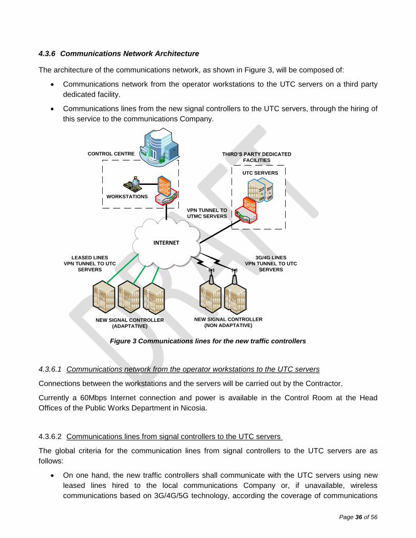
4.3.6 Communications Network Architecture .................................................................. 36
4.3.7 Public Transport Priority ........................................................................................ 38
4.4 Civil works ................................................................................................................. 40
4.4.1 General requirements ............................................................................................ 40
4.4.2 S2 type ducting trench and backfilling.................................................................... 40
4.4.3 S2A type narrow ducting trench and backfilling ..................................................... 41
4.4.4 FB type chambers ................................................................................................. 41
4.5 Testing ...................................................................................................................... 41
4.5.1 General requirements ............................................................................................ 41
4.5.2 Factory Acceptance Test (FAT) ............................................................................. 42
Page 4
Page 3 of 56
4.5.3 Software Factory Acceptance Test (SFAT) ............................................................ 43
4.5.4 Site Acceptance Test (SAT) .................................................................................. 43
4.5.5 Systems Integration Test (SIT) .............................................................................. 43
4.6 Training and initial operational support ...................................................................... 44
4.7 Maintenance .............................................................................................................. 45
4.8 Other Work requirements .......................................................................................... 46
4.8.1 Equipment installation ............................................................................................ 46
4.8.2 Health and safety measures .................................................................................. 47
4.8.3 Traffic safety measures ......................................................................................... 48
4.8.4 Delivery of removed equipment and waste management requirements ................. 50
4.8.5 Injury Insurance for Persons and Property............................................................. 51
4.9 Project Management ................................................................................................. 51
4.9.1 Competent Service and Recipient of Services ....................................................... 51
4.9.2 Organisational structure......................................................................................... 51
5. LOCATION AND DURATION OF CONTRACT SCOPE IMPLEMENTATION ................... 53
5.1 Location of Contract Scope implementation .............................................................. 53
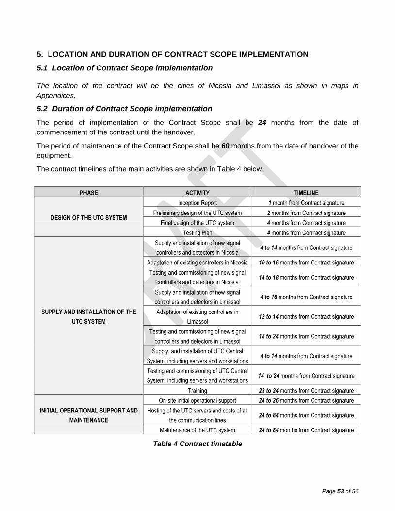
5.2 Duration of Contract Scope implementation .............................................................. 53
6. REQUIREMENTS ............................................................................................................. 54
6.1 Office accommodation ............................................................................................... 54
6.2 Facilities to be provided by the Contractor ................................................................. 54
6.3 Supporting resources provided by the Contracting Authority ..................................... 54
7. REPORTS ......................................................................................................................... 54
7.1 Reporting requirements ............................................................................................. 54
APPENDICES ........................................................................................................................ 56
APPENDIX A_NICOSIA UTMC SCOPE ........................................................................... 56
APPENDIX B_ NICOSIA SIGNAL CONTROLLERS ......................................................... 56
APPENDIX C_ NICOSIA BUS PRIORITY CORRIDORS .................................................. 56
APPENDIX D_ NICOSIA AVAILABLE COMMUNICATIONS ............................................ 56
APPENDIX E_LIMASSOL_UTMC SCOPE ....................................................................... 56
APPENDIX F_ LIMASSOL SIGNAL CONTROLLERS ..................................................... 56
Page 5
Page 4 of 56
APPENDIX G_ LIMASSOL BUS PRIORITY CORRIDORS .............................................. 56
APPENDIX H_ LIMASSOL_ SCOOT INFRASTRUCTURE .............................................. 56
List of figures
Figure 1 Junctions and corridor under the UTC scope of the project in Nicosia ................................. 10
Figure 2 Junctions and corridor under the UTC scope of the project in Limassol ............................... 14
Figure 3 Communications lines for the new traffic controllers ............................................................ 36
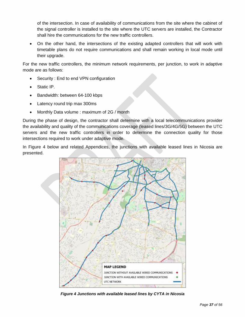
Figure 4 Junctions with available leased lines by CYTA in Nicosia .................................................... 37
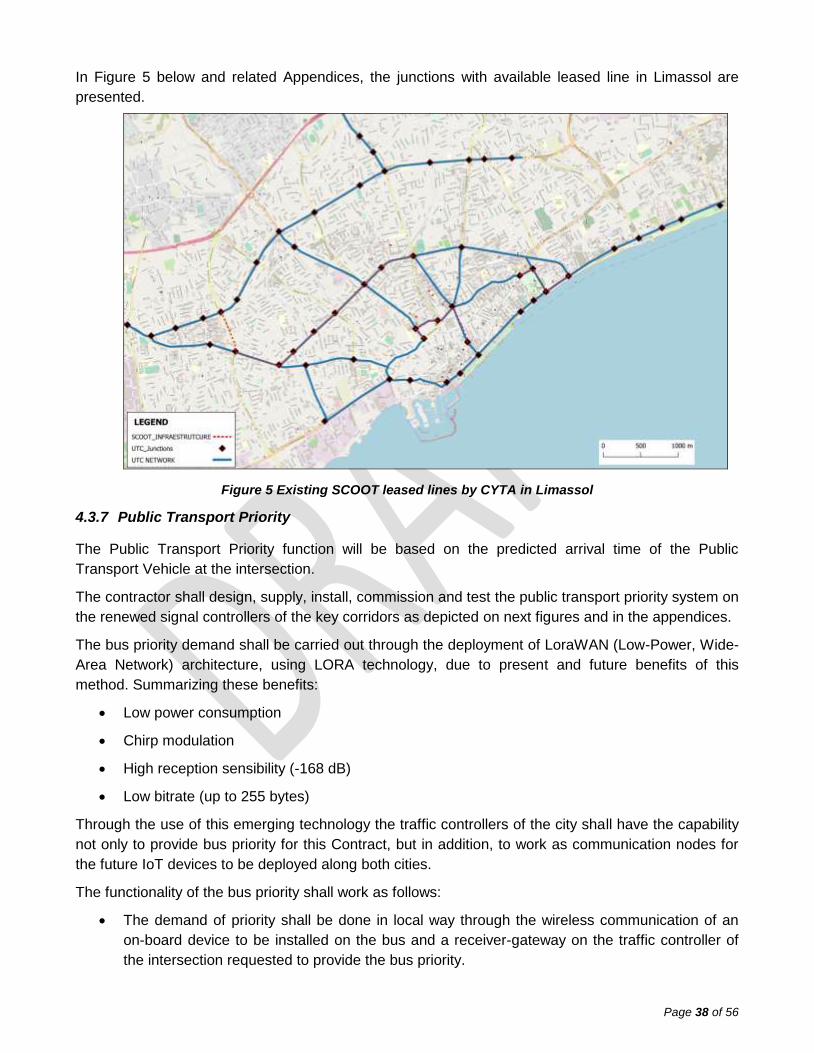
Figure 5 Existing SCOOT leased lines by CYTA in Limassol ............................................................. 38
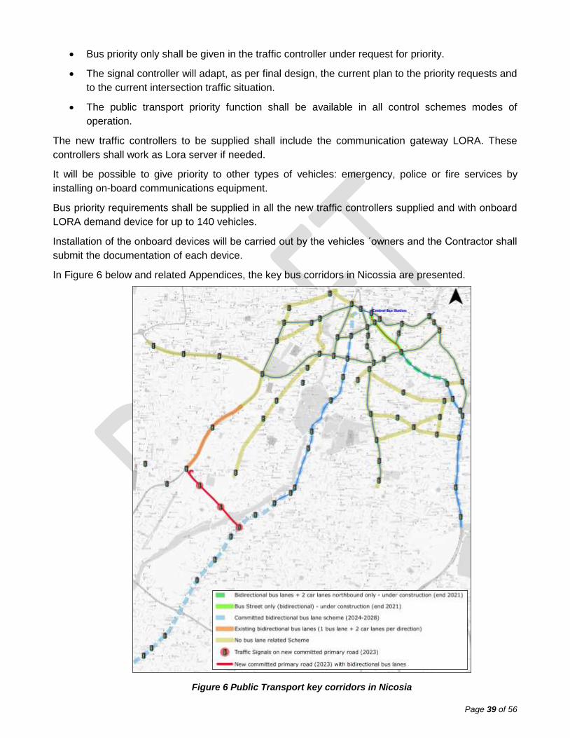
Figure 6 Public Transport key corridors in Nicosia ............................................................................. 39
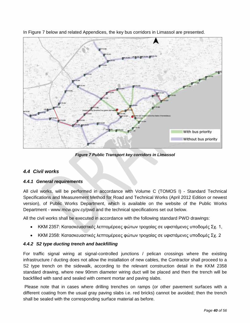
Figure 7 Public Transport key corridors in Limassol ........................................................................... 40
Figure 8 Work on sidewalks ............................................................................................................... 50
List of tables
Table 1 Existing controllers under the UTC scope of the project in Nicosia........................................ 10
Table 2 Existing controllers under the UTC scope of the project in Limassol ..................................... 13
Table 3 Classification according to EN 50556:2018 ........................................................................... 33
Table 4 Contract timetable ................................................................................................................. 53
Page 6
Page 5 of 56
1. BACKGROUND INFORMATION
1.1 Current state of affairs in the relevant sector
The Public Works Department (PWD) of the Ministry of Transport, Communications and Works of the
Republic of Cyprus currently has an outdated UTC SCOOT system, initially installed on 1992-1993,
with analogue communications, older software versions and in some junctions has obsolete
equipment or is out of service.
1.2 Relevant programmes and actions
The PWD, over the last years, has carried out initiatives, via EU funded projects, for the gradual
renewal of the signal hardware equipment, mainly in Nicosia, until February 2021.
Project KPS/42/2018/G(A) started in February 2019 and completed in March 2021 in Nicosia with the
replacement of signal equipment at 69 signalized junctions and 36 Pelican crossings. Similar projects
will follow for the cities of Limassol, Paphos, Larnaca and Famagusta from June 2021 until the end of
2023 in order to replace more outdated equipment with new ELV/LED equipment.
Other projects to upgrade the public transport system with new lines and vehicles are also under
development Cyprus wide.
2. OBJECTIVE, PURPOSE AND EXPECTED RESULTS
2.1 Overall objective
The scope of this contract is the supply, installation and 5-year maintenance of a new UTC/UMTC
(Urban Traffic Control / Urban Traffic Management & Control) for the cities of Nicosia and Limassol.
The specific objectives are:
Supply and installation of a new UTC System, based on open standard protocols, which will
operate in the cities of Nicosia and Limassol. The system shall have the capacity to operate in
adaptive mode and provide public transport vehicles priority.
Renewal of the existing traffic signal controllers of 70 junctions (23 in Nicosia and 47 in
Limassol), including vehicle detection systems if needed.
The servers of the UTC System will be hosted at a third’s party dedicated facilities.
Adaptation of 53 existing junctions (49 in Nicosia and 4 in Limassol) and preparation of the
new UTC System for their integration if it is possible in the future.
Training and initial operational support to PWD Staff.
5 year maintenance of the system.
2.2 Expected results
The implementation of the new UTC System will have the following results:
Improvement of traffic flow and road network efficiency.
Reduction of congestion and travel times.
Page 7
Page 6 of 56
Enhancement of public transport.
Improve road user safety.
Reduction of vehicle related emissions.
Open and State-of-the-art system which will allow growth both for the incorporation of new
equipment and new functionalities in the future.
3. ASSUMPTIONS AND RISKS
3.1 Assumptions underlying the implementation of the Contract
The main factor considered is that during the KPS/42/2018/G(A) Project, 49 controllers within the
scope of the contract have been renewed in Nicosia over the last 2 years.
These controllers currently do not have the all necessary elements for their communication over a
standard protocol. Even with the use of standards protocols, the integration of the advanced
functionalities, as the adaptive mode, is unlikely due to the lack of interoperability between different
manufacturers.
It should be assumed that because this investment is so recent, these controllers cannot be replaced.
This situation will limit the actions and scopes to be developed on this equipment during the project.
Other assumptions underlying the implementation of the Contract are:
Availability of communication lines to contract for the connection of the new equipment to the
central system.
Availability of power supply at junctions.
Availability of conduits for the new equipment connection.
Availability of complete information on existing equipment.
Availability of installing priority equipment on public transport vehicles.
3.2 Risks
The main risks associated with non-fulfilment with the above assumptions are:
Assumption of availability of communication.
o The non-existence of a communications network would imply the impossibility of
centralizing the junction equipment.
o If the minimum requirements defined on this document are not met, operation in
adaptive mode would not be possible.
Availability of power supply. In the event of not having sufficient electricity supply, it would be
necessary to increase the contracted power, which would imply an increase in the cost and
time of the implementation.
Availability of conduits. In case of not having the conduits, it would be necessary to build a new
one, which would mean an increase in the cost and in the implementation time.
Page 8
Page 7 of 56
Availability of complete information on existing equipment. In case of not having complete and
reliable information, it will condition the result of the preliminary and final designs.
Availability of installing priority equipment on public transport vehicles. If the implementation of
on-board equipment is not possible, it would make it impossible to implement the solution
presented in this document.
4. CONTRACT SCOPE
4.1 Current state of affairs
The Public Works Department (PWD) of the Ministry of Transport, Communications and Works of the
Republic of Cyprus currently has an outdated UTC SCOOT system with analogue communications,
older software versions and in some junctions has obsolete equipment or is out of service.
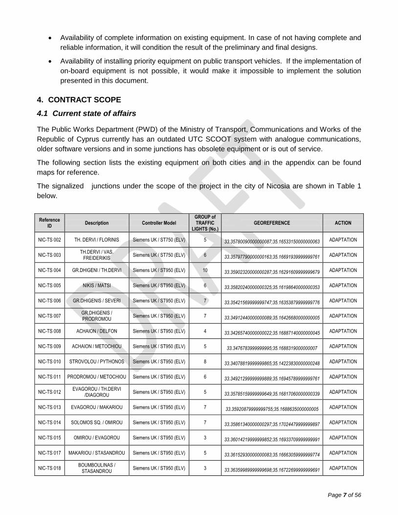
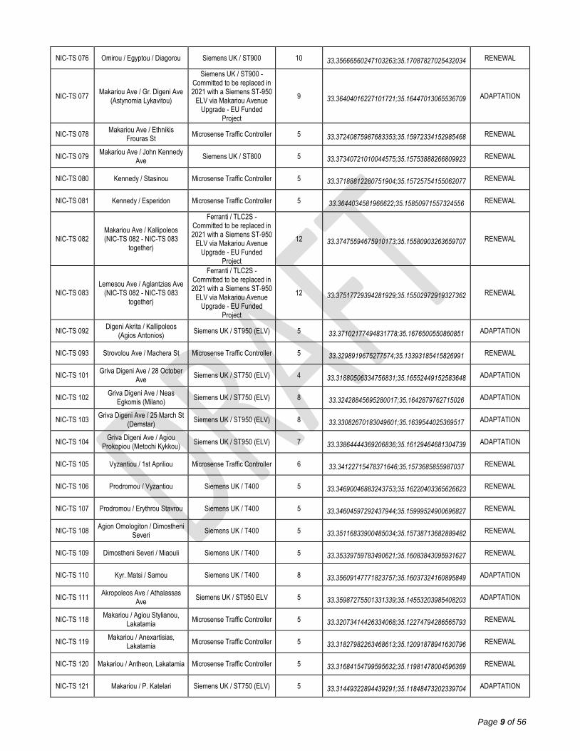
The following section lists the existing equipment on both cities and in the appendix can be found
maps for reference.
The signalized junctions under the scope of the project in the city of Nicosia are shown in Table 1
below.
Reference ID
Description Controller Model GROUP of TRAFFIC
LIGHTS (No.) GEOREFERENCE ACTION
NIC-TS 002 TH. DERVI / FLORINIS Siemens UK / ST750 (ELV) 5 33.35780090000000087;35.16533150000000063 ADAPTATION
NIC-TS 003 TH.DERVI / VAS.
FREIDERIKIS Siemens UK / ST750 (ELV) 6 33.35797790000000163;35.16691939999999761 ADAPTATION
NIC-TS 004 GR.DHIGENI / TH.DERVI Siemens UK / ST950 (ELV) 10 33.35902320000000287;35.16291609999999679 ADAPTATION
NIC-TS 005 NIKIS / MATSI Siemens UK / ST950 (ELV) 6 33.35820240000000325;35.16198640000000353 ADAPTATION
NIC-TS 006 GR.DHIGENIS / SEVERI Siemens UK / ST950 (ELV) 7 33.35421569999999747;35.16353879999999776 ADAPTATION
NIC-TS 007 GR.DHIGENIS / PRODROMOU
Siemens UK / ST950 (ELV) 7 33.34912440000000089;35.16426680000000005 ADAPTATION
NIC-TS 008 ACHAION / DELFON Siemens UK / ST950 (ELV) 4 33.34265740000000022;35.16887140000000045 ADAPTATION
NIC-TS 009 ACHAION / METOCHIOU Siemens UK / ST950 (ELV) 5 33.3476783999999995;35.1688319000000007 ADAPTATION
NIC-TS 010 STROVOLOU / PYTHONOS Siemens UK / ST950 (ELV) 8 33.34078819999999865;35.14223830000000248 ADAPTATION
NIC-TS 011 PRODROMOU / METOCHIOU Siemens UK / ST950 (ELV) 6 33.34921299999999889;35.16945789999999761 ADAPTATION
NIC-TS 012 EVAGOROU / TH.DERVI
/DIAGOROU Siemens UK / ST950 (ELV) 5 33.35785159999999649;35.16817060000000339 ADAPTATION
NIC-TS 013 EVAGOROU / MAKARIOU Siemens UK / ST950 (ELV) 7 33.35920879999999755;35.1688635000000005 ADAPTATION
NIC-TS 014 SOLOMOS SQ. / OMIROU Siemens UK / ST950 (ELV) 7 33.35861340000000297;35.17024479999999897 ADAPTATION
NIC-TS 015 OMIROU / EVAGOROU Siemens UK / ST950 (ELV) 3 33.36014219999999852;35.16933709999999991 ADAPTATION
NIC-TS 017 MAKARIOU / STASANDROU Siemens UK / ST950 (ELV) 5 33.36152930000000083;35.16663059999999774 ADAPTATION
NIC-TS 018 BOUMBOULINAS /
STASANDROU Siemens UK / ST950 (ELV) 3 33.36359989999999698;35.16722699999999691 ADAPTATION
Page 9
Page 8 of 56
NIC-TS 019 STASINOU /
BOUMBOULINAS Siemens UK / ST950 (ELV) 4 33.36417930000000354;35.16864350000000172 ADAPTATION
NIC-TS 020 STASINOU / E & A
THEODOTOU Siemens UK / ST900 0 33.3691578999999976;35.16974410000000262 RENEWAL
NIC-TS 024 GR. DHIGENI / VYRONOS Siemens UK / ST950 (ELV) 6 33.35169049999999658;35.16394749999999902 ADAPTATION
NIC-TS 025 ELEONON /
MAKAEDONITISSIS Siemens UK / ST750 (ELV) 8 33.3337444000000005;35.14676359999999988 ADAPTATION
NIC-TS 026 STROVOLOU / EVZONON Siemens UK / ST750 (ELV) 6 33.33281980000000289;35.13733580000000245 ADAPTATION
NIC-TS 028 SP.KYPRIANOU / MARKORA Siemens UK / ST950 (ELV) 6 33.36086790000000235;35.16342730000000216 ADAPTATION
NIC-TS 029 EVAGOROU / M.KARAOLI Siemens UK / ST950 (ELV) 5 33.35488289999999978;35.16689389999999804 ADAPTATION
NIC-TS 030 L.VYRONOS / M. KARAOLI Siemens UK / ST900 5 33.35240449999999868;35.1666706999999974 RENEWAL
NIC-TS 034 IFIGENIAS / SAN SOUSI Siemens UK / ST750 (ELV) 6 33.37106109999999859;35.15486580000000316 ADAPTATION
NIC-TS 035 LEMESOU / RIK Siemens UK / ST950 (ELV) 6 33.37389019999999817;35.14448050000000023 ADAPTATION
NIC-TS 036 STROVOLOU / ATHALASSA Siemens UK / ST950 (ELV) 6 33.34698809999999725;35.15032159999999806 ADAPTATION
NIC-TS 037 AKROPOLEOS / ARSINOIS Siemens UK / ST950 (ELV) 8 33.35842499999999688;35.15535679999999985 ADAPTATION
NIC-TS 038 IFIGENIAS / ARMENIAS Siemens UK / ST750 (ELV) 7 33.36627849999999995;35.15338309999999922 ADAPTATION
NIC-TS 040 STROVOLOS / PERIKLEOUS Siemens UK / ST950 (ELV) 6 33.34451339999999675;35.14455110000000104 ADAPTATION
NIC-TS 041 STROVOLOU / ATHINON Siemens UK / ST950 (ELV) 5 33.34375169999999855;35.14374829999999861 ADAPTATION
NIC-TS 042 ARCH. KYPRIANOU /
STROVOLOU Siemens UK / ST950 (ELV) 4 33.34762860000000018;35.15279579999999982 ADAPTATION
NIC-TS 043 AKROPOLEOS / KORITSAS Siemens UK / ST750 (ELV) 8 33.35946880000000192;35.15151060000000172 ADAPTATION
NIC-TS 045 LEMESOU / ARMENIAS Siemens UK / ST950 (ELV) 0 33.37454660000000217;35.15180999999999756 ADAPTATION
NIC-TS 046 ELEONON / STADIOU Siemens UK / ST750 (ELV) 10 33.33881170000000083;35.15473850000000056 ADAPTATION
NIC-TS 051 ARMENIAS - STASINOU Siemens UK / ST750 (ELV) 6 33.37048360000000002;35.15228489999999795 ADAPTATION
NIC-TS 053 ACROPOLEOS / 28
OCTOBER Siemens UK / ST750 (ELV) 9 33.35994780000000048;35.14842500000000314 ADAPTATION
NIC-TS 055 STROVOLOU / KANTARAS Siemens UK / ST750 (ELV) 8 33.33729749999999825;35.14052050000000094 ADAPTATION
NIC-TS 056 DELPHON/NAVARINOU/POU
LIOU Siemens UK / ST750 (ELV) 6 33.34358290000000125;35.17101770000000016 ADAPTATION
NIC-TS 059 ATHALASSAS / LEMESOU Siemens UK / ST950 (ELV) 6 33.37478260000000319;35.14009149999999693 ADAPTATION
NIC-TS 062 AG.PROKOPIOU /
METOCHIO Siemens UK / ST950 (ELV) 7 33.34133010000000041;35.16616650000000277 ADAPTATION
NIC-TS 070 Kallipoleos / Ethnikis Frouras Siemens UK / ST950 (ELV) 5 33.37515995064310914;35.16002647993777686 ADAPTATION
NIC-TS 071 Armenias / Esperidon Siemens UK / ST750 (LV) 5 33.36331149478515101;35.15480415381843216 RENEWAL
NIC-TS 074 Louki Akrita / Iroon / Metochiou Microsense Traffic Controller 6 33.35106583305492478;35.17314858147760503 RENEWAL
NIC-TS 075 Omirou / Vyronos / Mousiou Ferranti / TLC2S 7 33.35503619966364397;35.17157461057357892 RENEWAL
Page 10
Page 9 of 56
NIC-TS 076 Omirou / Egyptou / Diagorou Siemens UK / ST900 10 33.35666560247103263;35.17087827025432034 RENEWAL
NIC-TS 077 Makariou Ave / Gr. Digeni Ave
(Astynomia Lykavitou)
Siemens UK / ST900 - Committed to be replaced in 2021 with a Siemens ST-950
ELV via Makariou Avenue Upgrade - EU Funded
Project
9 33.36404016227101721;35.16447013065536709 ADAPTATION
NIC-TS 078 Makariou Ave / Ethnikis
Frouras St Microsense Traffic Controller 5 33.37240875987683353;35.15972334152985468 RENEWAL
NIC-TS 079 Makariou Ave / John Kennedy
Ave Siemens UK / ST800 5 33.37340721010044575;35.15753888266809923 RENEWAL
NIC-TS 080 Kennedy / Stasinou Microsense Traffic Controller 5 33.37188812280751904;35.15725754155062077 RENEWAL
NIC-TS 081 Kennedy / Esperidon Microsense Traffic Controller 5 33.3644034581966622;35.15850971557324556 RENEWAL
NIC-TS 082 Makariou Ave / Kallipoleos (NIC-TS 082 - NIC-TS 083
together)
Ferranti / TLC2S - Committed to be replaced in 2021 with a Siemens ST-950
ELV via Makariou Avenue Upgrade - EU Funded
Project
12 33.37475594675910173;35.15580903263659707 RENEWAL
NIC-TS 083 Lemesou Ave / Aglantzias Ave
(NIC-TS 082 - NIC-TS 083 together)
Ferranti / TLC2S - Committed to be replaced in 2021 with a Siemens ST-950
ELV via Makariou Avenue Upgrade - EU Funded
Project
12 33.37517729394281929;35.15502972919327362 RENEWAL
NIC-TS 092 Digeni Akrita / Kallipoleos
(Agios Antonios) Siemens UK / ST950 (ELV) 5 33.37102177494831778;35.1676500550860851 ADAPTATION
NIC-TS 093 Strovolou Ave / Machera St Microsense Traffic Controller 5 33.3298919675277574;35.13393185415826991 RENEWAL
NIC-TS 101 Griva Digeni Ave / 28 October
Ave Siemens UK / ST750 (ELV) 4 33.31880506334756831;35.16552449152583648 ADAPTATION
NIC-TS 102 Griva Digeni Ave / Neas
Egkomis (Milano) Siemens UK / ST750 (ELV) 8 33.32428845695280017;35.1642879762715026 ADAPTATION
NIC-TS 103 Griva Digeni Ave / 25 March St
(Demstar) Siemens UK / ST950 (ELV) 8 33.33082670183049601;35.1639544025369517 ADAPTATION
NIC-TS 104 Griva Digeni Ave / Agiou
Prokopiou (Metochi Kykkou) Siemens UK / ST950 (ELV) 7 33.33864444369206836;35.16129464681304739 ADAPTATION
NIC-TS 105 Vyzantiou / 1st Apriliou Microsense Traffic Controller 6 33.34122715478371646;35.1573685855987037 RENEWAL
NIC-TS 106 Prodromou / Vyzantiou Siemens UK / T400 5 33.34690046883243753;35.16220403365626623 RENEWAL
NIC-TS 107 Prodromou / Erythrou Stavrou Siemens UK / T400 5 33.34604597292437944;35.15999524900696827 RENEWAL
NIC-TS 108 Agion Omologiton / Dimostheni
Severi Siemens UK / T400 5 33.35116833900485034;35.15738713682889482 RENEWAL
NIC-TS 109 Dimostheni Severi / Miaouli Siemens UK / T400 5 33.35339759783490621;35.16083843095931627 RENEWAL
NIC-TS 110 Kyr. Matsi / Samou Siemens UK / T400 8 33.35609147771823757;35.16037324160895849 ADAPTATION
NIC-TS 111 Akropoleos Ave / Athalassas
Ave Siemens UK / ST950 ELV 5 33.35987275501331339;35.14553203985408203 ADAPTATION
NIC-TS 118 Makariou / Agiou Stylianou,
Lakatamia Microsense Traffic Controller 5 33.32073414426334068;35.12274794286565793 RENEWAL
NIC-TS 119 Makariou / Anexartisias,
Lakatamia Microsense Traffic Controller 5 33.31827982263468613;35.12091878941630796 RENEWAL
NIC-TS 120 Makariou / Antheon, Lakatamia Microsense Traffic Controller 5 33.31684154799595632;35.11981478004596369 RENEWAL
NIC-TS 121 Makariou / P. Katelari Siemens UK / ST750 (ELV) 5 33.31449322894439291;35.11848473202339704 ADAPTATION
Page 11
Page 10 of 56
NIC-TS 134 Pindarou/ E. & A. Theodotou Ferranti / TLC2S 5 33.37003462905452977;35.16884315738363398 RENEWAL
NIC-TS 141 Strovolou / P. Mela Microsense Traffic Controller 5 33.32661926678984798;35.13091901474133749 RENEWAL
Table 1 Existing controllers under the UTC scope of the project in Nicosia
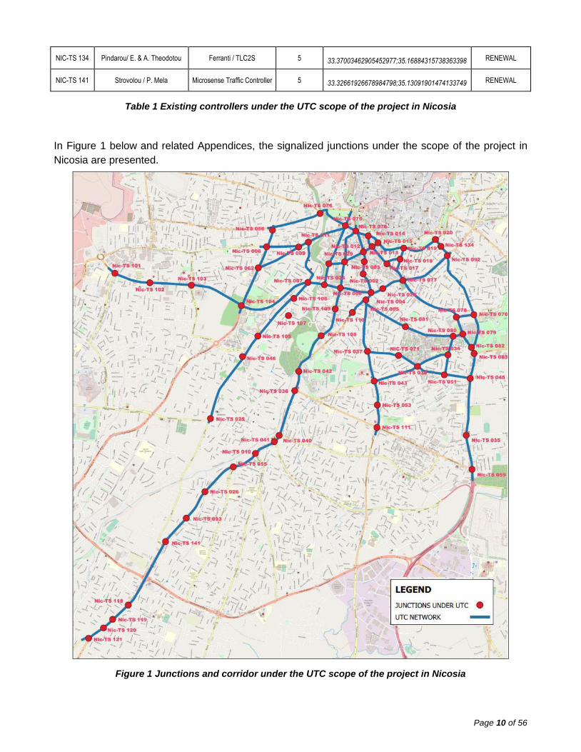
In Figure 1 below and related Appendices, the signalized junctions under the scope of the project in
Nicosia are presented.
Figure 1 Junctions and corridor under the UTC scope of the project in Nicosia
Page 12
Page 11 of 56
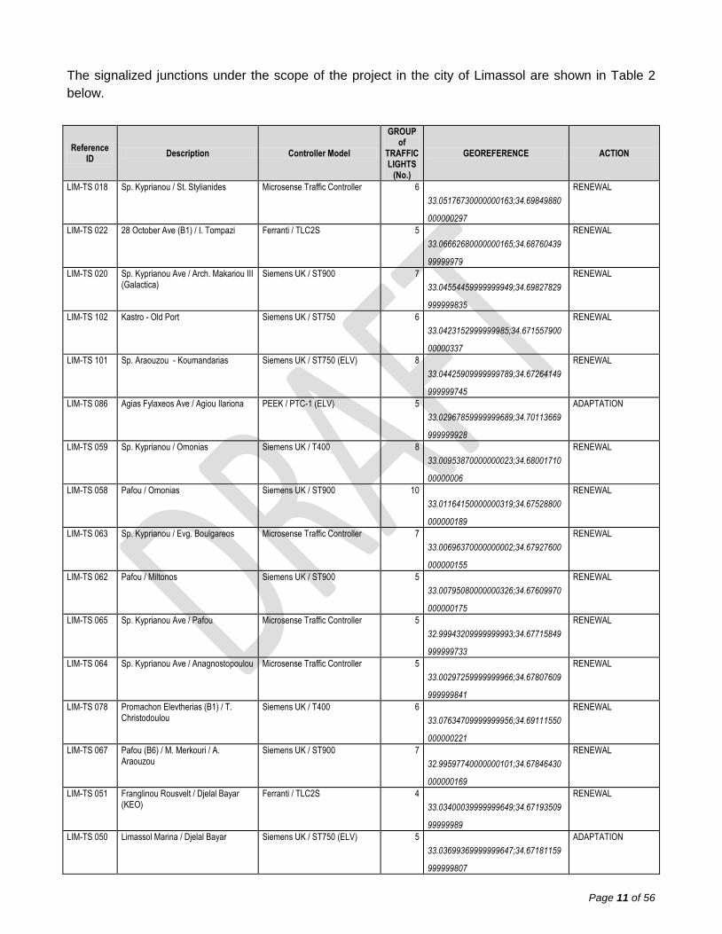
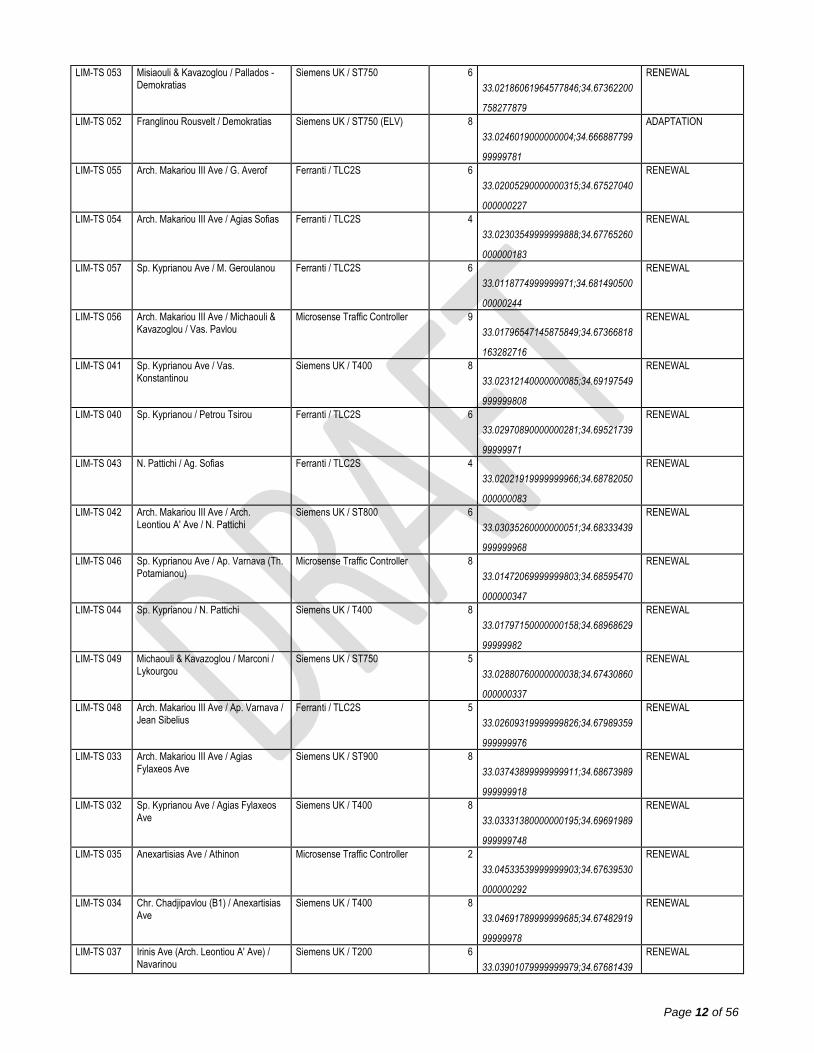
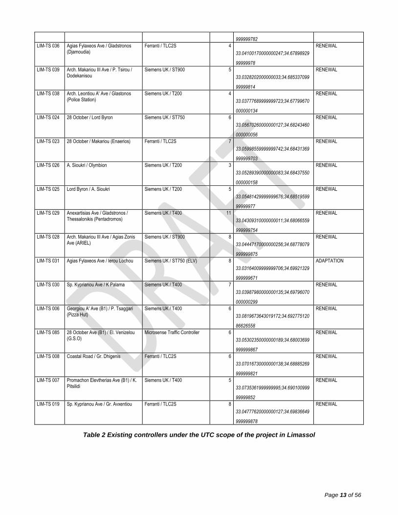
The signalized junctions under the scope of the project in the city of Limassol are shown in Table 2
below.
Reference ID
Description Controller Model
GROUP of
TRAFFIC LIGHTS
(No.)
GEOREFERENCE ACTION
LIM-TS 018 Sp. Kyprianou / St. Stylianides Microsense Traffic Controller 6
33.05176730000000163;34.69849880
000000297
RENEWAL
LIM-TS 022 28 October Ave (B1) / I. Tompazi Ferranti / TLC2S 5
33.06662680000000165;34.68760439
99999979
RENEWAL
LIM-TS 020 Sp. Kyprianou Ave / Arch. Makariou III (Galactica)
Siemens UK / ST900 7
33.04554459999999949;34.69827829
999999835
RENEWAL
LIM-TS 102 Kastro - Old Port Siemens UK / ST750 6
33.0423152999999985;34.671557900
00000337
RENEWAL
LIM-TS 101 Sp. Araouzou - Koumandarias Siemens UK / ST750 (ELV) 8
33.04425909999999789;34.67264149
999999745
RENEWAL
LIM-TS 086 Agias Fylaxeos Ave / Agiou Ilariona PEEK / PTC-1 (ELV) 5
33.02967859999999689;34.70113669
999999928
ADAPTATION
LIM-TS 059 Sp. Kyprianou / Omonias Siemens UK / T400 8
33.00953870000000023;34.68001710
00000006
RENEWAL
LIM-TS 058 Pafou / Omonias Siemens UK / ST900 10
33.01164150000000319;34.67528800
000000189
RENEWAL
LIM-TS 063 Sp. Kyprianou / Evg. Boulgareos Microsense Traffic Controller 7
33.00696370000000002;34.67927600
000000155
RENEWAL
LIM-TS 062 Pafou / Miltonos Siemens UK / ST900 5
33.00795080000000326;34.67609970
000000175
RENEWAL
LIM-TS 065 Sp. Kyprianou Ave / Pafou Microsense Traffic Controller 5
32.99943209999999993;34.67715849
999999733
RENEWAL
LIM-TS 064 Sp. Kyprianou Ave / Anagnostopoulou Microsense Traffic Controller 5
33.00297259999999966;34.67807609
999999841
RENEWAL
LIM-TS 078 Promachon Elevtherias (B1) / T. Christodoulou
Siemens UK / T400 6
33.07634709999999956;34.69111550
000000221
RENEWAL
LIM-TS 067 Pafou (B6) / M. Merkouri / A. Araouzou
Siemens UK / ST900 7
32.99597740000000101;34.67846430
000000169
RENEWAL
LIM-TS 051 Franglinou Rousvelt / Djelal Bayar (KEO)
Ferranti / TLC2S 4
33.03400039999999649;34.67193509
99999989
RENEWAL
LIM-TS 050 Limassol Marina / Djelal Bayar Siemens UK / ST750 (ELV) 5
33.03699369999999647;34.67181159
999999807
ADAPTATION
Page 13
Page 12 of 56
LIM-TS 053 Misiaouli & Kavazoglou / Pallados - Demokratias
Siemens UK / ST750 6
33.02186061964577846;34.67362200
758277879
RENEWAL
LIM-TS 052 Franglinou Rousvelt / Demokratias Siemens UK / ST750 (ELV) 8
33.0246019000000004;34.666887799
99999781
ADAPTATION
LIM-TS 055 Arch. Makariou III Ave / G. Averof Ferranti / TLC2S 6
33.02005290000000315;34.67527040
000000227
RENEWAL
LIM-TS 054 Arch. Makariou III Ave / Agias Sofias Ferranti / TLC2S 4
33.02303549999999888;34.67765260
000000183
RENEWAL
LIM-TS 057 Sp. Kyprianou Ave / M. Geroulanou Ferranti / TLC2S 6
33.0118774999999971;34.681490500
00000244
RENEWAL
LIM-TS 056 Arch. Makariou III Ave / Michaouli & Kavazoglou / Vas. Pavlou
Microsense Traffic Controller 9
33.01796547145875849;34.67366818
163282716
RENEWAL
LIM-TS 041 Sp. Kyprianou Ave / Vas. Konstantinou
Siemens UK / T400 8
33.02312140000000085;34.69197549
999999808
RENEWAL
LIM-TS 040 Sp. Kyprianou / Petrou Tsirou Ferranti / TLC2S 6
33.02970890000000281;34.69521739
99999971
RENEWAL
LIM-TS 043 N. Pattichi / Ag. Sofias Ferranti / TLC2S 4
33.02021919999999966;34.68782050
000000083
RENEWAL
LIM-TS 042 Arch. Makariou III Ave / Arch. Leontiou A' Ave / N. Pattichi
Siemens UK / ST800 6
33.03035260000000051;34.68333439
999999968
RENEWAL
LIM-TS 046 Sp. Kyprianou Ave / Ap. Varnava (Th. Potamianou)
Microsense Traffic Controller 8
33.01472069999999803;34.68595470
000000347
RENEWAL
LIM-TS 044 Sp. Kyprianou / N. Pattichi Siemens UK / T400 8
33.01797150000000158;34.68968629
99999982
RENEWAL
LIM-TS 049 Michaouli & Kavazoglou / Marconi / Lykourgou
Siemens UK / ST750 5
33.02880760000000038;34.67430860
000000337
RENEWAL
LIM-TS 048 Arch. Makariou III Ave / Ap. Varnava / Jean Sibelius
Ferranti / TLC2S 5
33.02609319999999826;34.67989359
999999976
RENEWAL
LIM-TS 033 Arch. Makariou III Ave / Agias Fylaxeos Ave
Siemens UK / ST900 8
33.03743899999999911;34.68673989
999999918
RENEWAL
LIM-TS 032 Sp. Kyprianou Ave / Agias Fylaxeos Ave
Siemens UK / T400 8
33.03331380000000195;34.69691989
999999748
RENEWAL
LIM-TS 035 Anexartisias Ave / Athinon Microsense Traffic Controller 2
33.04533539999999903;34.67639530
000000292
RENEWAL
LIM-TS 034 Chr. Chadjipavlou (B1) / Anexartisias Ave
Siemens UK / T400 8
33.04691789999999685;34.67482919
99999978
RENEWAL
LIM-TS 037 Irinis Ave (Arch. Leontiou A' Ave) / Navarinou
Siemens UK / T200 6
33.03901079999999979;34.67681439
RENEWAL
Page 14
Page 13 of 56
999999782
LIM-TS 036 Agias Fylaxeos Ave / Gladstronos (Djamoudia)
Ferranti / TLC2S 4
33.04100170000000247;34.67898929
99999978
RENEWAL
LIM-TS 039 Arch. Makariou III Ave / P. Tsirou / Dodekanisou
Siemens UK / ST900 5
33.0328202000000033;34.685337099
99999814
RENEWAL
LIM-TS 038 Arch. Leontiou A' Ave / Glastonos (Police Station)
Siemens UK / T200 4
33.03777689999999723;34.67799670
000000134
RENEWAL
LIM-TS 024 28 October / Lord Byron Siemens UK / ST750 6
33.05670260000000127;34.68243460
000000056
RENEWAL
LIM-TS 023 28 October / Makariou (Enaerios) Ferranti / TLC2S 7
33.05998559999999742;34.68431369
999999703
RENEWAL
LIM-TS 026 A. Sioukri / Olymbion Siemens UK / T200 3
33.05289390000000083;34.68437550
000000158
RENEWAL
LIM-TS 025 Lord Byron / A. Sioukri Siemens UK / T200 5
33.05481429999999676;34.68519599
99999977
RENEWAL
LIM-TS 029 Anexartisias Ave / Gladstronos / Thessalonikis (Pentadromos)
Siemens UK / T400 11
33.04309310000000011;34.68066559
999999754
RENEWAL
LIM-TS 028 Arch. Makariou III Ave / Agias Zonis Ave (ARIEL)
Siemens UK / ST900 8
33.04447170000000256;34.68778079
999999875
RENEWAL
LIM-TS 031 Agias Fylaxeos Ave / Ierou Lochou Siemens UK / ST750 (ELV) 8
33.03164009999999706;34.69921329
999999671
ADAPTATION
LIM-TS 030 Sp. Kyprianou Ave / K Palama Siemens UK / T400 7
33.03987980000000135;34.69796070
000000299
RENEWAL
LIM-TS 006 Georgiou A' Ave (B1) / P. Tsaggari (Pizza Hut)
Siemens UK / T400 6
33.0819673643019172;34.692775120
86626558
RENEWAL
LIM-TS 085 28 October Ave (B1) / El. Venizelou (G.S.O)
Microsense Traffic Controller 6
33.05302350000000189;34.68003699
999999867
RENEWAL
LIM-TS 008 Coastal Road / Gr. Dhigenis Ferranti / TLC2S 6
33.07016730000000138;34.68885269
999999821
RENEWAL
LIM-TS 007 Promachon Elevtherias Ave (B1) / K. Pitsilidi
Siemens UK / T400 5
33.0735361999999995;34.690100999
99999852
RENEWAL
LIM-TS 019 Sp. Kyprianou Ave / Gr. Avxentiou Ferranti / TLC2S 8
33.04777620000000127;34.69836649
999999878
RENEWAL
Table 2 Existing controllers under the UTC scope of the project in Limassol
Page 15
Page 14 of 56
In Figure 2 below and related Appendices, the signalized junctions under the scope of the project in
Limassol are presented.
Figure 2 Junctions and corridor under the UTC scope of the project in Limassol
Page 16
Page 15 of 56
4.2 Activity breakdown
The scope of this contract is the Supply, installation and 5-year maintenance of a new UTC/UMTC
(Urban Traffic Control / Urban Traffic Management & Control) for the cities of Nicosia and Limassol.
The project will have three main phases: Design of the UTC system, Supply and installation of the
UTC System and finally the Initial Operational support and maintenance.
The main activities which must be carried out in order for the objective of the contract to be achieved
will be (in addition to the reports/ deliverables stated in paragraph 7.1):
PHASE 1: DESIGN OF THE UTC SYSTEM (4 months)
a) Preliminary design of the UTC system under the scope of the project, without including the
traffic engineering, within 2 months from Contract signature, for the approval the Contract
Coordinator. In general, the preliminary design shall provide conceptual view of the proposed
solution sufficient to satisfy user needs but may not have the details of implementation and
integration fully developed. The preliminary design will include the requirements gathering, the
initial site survey results (not including the traffic engineering), risk analysis, proposed systems
and technical specifications.
b) Final design of the UTC system under the scope of the project, without including the traffic
engineering, within 4 months from Contract signature, for the approval the Contract
Coordinator. The final design will include the final systems and technical specifications,
hardware and software configuration, provide interface control details, users, interfacing
systems, states and modes of operation, capabilities, objectives, locations and
communications.
c) Testing Plan, within 4 months from Contract signature, for the approval the Contract
Coordinator, that shows the procedures to ensure all sub systems, hardware and software are
performing correctly and as per the requirements. The Plan shall include Factory Acceptance
Test, Software Factory Acceptance Test, Site Acceptance Test and Systems Integration Test
as defined in section 4.5.
PHASE 2: SUPPLY AND INSTALLATION OF THE UTC SYSTEM (20 months)
d) Supply, installation, commissioning and testing of a new UTC System which will manage the
cities of Nicosia and Limassol, within the period of implementation stated in paragraph 5.2.
o Shall have all the functionalities defined in section 4.3.1, including the ability to operate
in adaptive mode and provide public transport priority.
o Shall support at least 3 of the following 4 open and internationally recognized
standards for the communications between the traffic controllers and the new UTC
System:
(1) UTMC2 protocol
Page 17
Page 16 of 56
(2) NTCIP 1201 and NTCIP 1202 protocols
(3) AENOR/UNE 135401-4 protocol
(4) OCIT
o The servers of the UTC System shall be hosted at a third’s party dedicated facilities in
the cloud, through an internationally recognized service cloud supplier as AWS, Azure
or similar in a minimum TIER-III center as defined in section 4.3.1.
e) Supply, installation, commissioning and testing of the UTC operator workstations and console
furniture, as Control Center, at the Central Offices of the Public Works Department in Nicosia,
where the existing UTC/SCOOT system control centre is currently situated, within the period of
implementation stated in paragraph 5.2. Shall have all the functionalities define in section
4.3.2.
f) Renewal of the existing traffic signal controllers in 70 junctions (23 in Nicosia and 47 in
Limassol), within the period of implementation stated in paragraph 5.2. The works included are
as follows:
o Traffic engineering of the junction, including all site surveys and on-site works needed.
o Renewal of the existing signal controller, consisting of the supply, installation,
connection to the existing cabling of the traffic lights and to the existing cabling of
power supply and grounding, configuration, calibration, commissioning and testing of
the new controllers. The new controller shall have all the functionalities defined in
section 4.3.4.
o Supply, installation, connection to the signal controller, configuration, and calibration,
commissioning and testing of the new vehicle detector system in the junctions
determined according to the detailed design. The new detectors shall have all the
functionalities defined in section 4.3.5. and will be based on video detection.
o Integration, centralization of all the equipment into the new UTC system.
o Commissioning and testing of the public transport priority system on the renewed
signal controllers of the key corridors according to the detailed design and appendices.
o Disconnection and detachment, transport and delivery of the existing traffic controllers
to the place indicated by the contracting authority.
o Delivery of the final documentation: configuration files, junction drawings, wiring
drawings and charts.
g) Adaptation of 53 existing signal controllers (49 in Nicosia and 4 in Limassol), within period of
implementation stated in paragraph 5.2. The works included are as follows:
o Traffic engineering of the junction, with the following components:
Traffic site survey and flow vehicle analysis needed in order to determine the
optimal fixed time traffic plans.
Generation of the documentation with the optimal fixed time traffic plans
o Delivery of the above traffic engineering documentation to the authorities so that they
can update the controllers' plans.
Page 18
Page 17 of 56
h) Integration and centralization of the new controllers into the new UTC system and
configuration of the UTC for the future integration of the adapted controllers. The works
included are as follows:
o Configuration of the new UTC system for the new traffic controllers to allow their
communications and integration through the selected protocol as per final design.
o Configuration of the new UTC system for the adapted controllers to allow their
integration at any moment of the Contract once upgraded. For this purpose, non-
replaced traffic controllers, defined within this document as adapted controllers, will
work under local fixed times mode, with updated traffic plans generated and delivered
by the Contractor. But if at any moment during the duration of the Contract the
Authority upgrades these non-replaced controllers with all the needed hardware and
software pieces (licences, OTU, firmware, configuration tools,...) required to allow their
communications with the UTC via the above selected protocol, the contactor shall
integrate into the new UTC system, and as part of the Contract, the adapted signal
controller received in the UTC.
i) Contracting of the wired leased lines, if available, and/or 3G/4G/5G lines needed to implement
the new UTC Data Communication Network as defined in section 4.3.6, within the period of
implementation stated in paragraph 5.2, including all the equipment needed.
j) For the replacement of the new traffic controllers and installation of detectors, if needed, minor
civil works and small-scale substructures on road and sidewalk pavement such as cable
chambers, ducting civils, poles for detectors if required, or controller cabinet base. Prior to the
commencement of the above works in each junction, the Contractor shall submit to the
Contracting Authority construction drawings for approval, in which all the construction details
(chambers, trenches and ducting, poles for detectors, controller cabinets) are displayed. The
Civil works will be performed by a licensed Civil Works Sub-Contractor.
k) Collection, transport and disposal of waste generated by the works in a licensed facility, in
accordance with the Waste Laws of 2011 to 2016 and the current Regulations
l) Training, as defined in section 4.6, including:
o Training plan covering all subjects related to the configuration, commissioning,
installation, maintenance and operation of the systems included in this project.
o The Operational and maintenance training will be given to Officers of the Public Works
Department and to the Union of Municipalities of Cyprus.
m) Handover of the equipment and start of the operation by the Public Works Department.
Page 19
Page 18 of 56
PHASE 3: INITIAL OPERATIONAL SUPPORT AND MAINTENANCE (60 months)
n) 60 days of on-site initial operational support, after the handover, to the Officers of the Public
Works Department including the preparation of an Operations Manual as defined in section
4.6.
o) Providing during 5 years the communication for the new controllers needed to link with the new
UTC System.
p) 5 year maintenance of the UTC system after the handover as defined in section 4.7. The
equipment (hardware and software) under the scope of the maintenance are the new UTC
System, the UTC workstations, the UTC servers and the communications.
4.3 Technical Specifications / Requirements
4.3.1 Urban Traffic Management & Control System (UTC System)
4.3.1.1 System overview
The Urban Traffic Management & Control Platform will be the solution for the integrated management
of the mobility in both cities: Nicosia and Limassol.
The contractor shall include in the design the compliance with all the requirements included in this
document.
The new UTC platform shall be based on open communication protocols to facilitate integration to
other traffic management systems in the future and must include a UTC user-friendly interface with
interactive maps for monitoring and control.
The architecture of the platform can be divided in the following layers:
Data collection: the platform shall collect, integrate and store the traffic information. This
information shall be both static and dynamic, even in real-time when communications allow it.
Data processing: elaborated data are made available for the management modules.
Operation and management: the platform shall enable to manage the infrastructure and
services that are under their responsibility.
Presentation: it includes all the user and operator interfaces for the publication of the data and
the interaction with the system.
The system must integrate, at least, the following functionalities:
Management of the basic infrastructure
Event management
Plan Management
Traffic data
Traffic control
Page 20
Page 19 of 56
Bus Priority
Data acquisition system (traffic controllers and traffic detectors)
Decision Support System (DSS)
GIS Map with zoom, and movement controls
User and roles management
Traffic and operations reports.
Key Performance Indexes (KPI) and dashboards.
Communications management
Monitoring of standards-based IP-videos from the video-detectors.
Remote Demand Activation for Traffic Controllers
Origin/Destination Matrix
API for ANPR devices
In addition the system must be compatible with the following emerging technologies:
V2I, V2V, V2X
Big Data
Internet of Things (IoT)
Artificial Intelligence (AI)
Green Light Optimized Speed Advisory (GLOSA)
4.3.1.2 Global requirements
The platform must be web based on web technology, Multilanguage and user/role-based
access controlled.
The system must be developed by modular design with all applications and interfaces required
integrated in one platform using a Service Oriented Architecture.
The systems shall scale to support the sizing of the project and future extensions
The platform must be built on a core that provides the tools (APIs and processes) that allow
developing its functionalities on a common platform with other systems.
Access control to the information and the management capacities of the system shall be
based on the definition of profiles and rights for each system user.
All hardware and software necessary components for the operation of the system must include
all the needed licensing
Based on open technologies, open source components and proven standards such as:
o Java EE.
Page 21
Page 20 of 56
o RDBMS: relational databases.
o HTML 5
o ESB (Enterprise Service Bus): systems integration framework
o GeoServer
o Messaging broker: message oriented middleware (MOM)
o Web Services
o REST
o RSS
o XML
o KML
o JSON
Shall support at least 3 of the following 4 open and internationally recognized standards for
device interaction and systems interfacing with signal controllers:
o (1) UTMC2 protocol
o (2) NTCIP 1201 and NTCIP 1202 protocols
o (3) AENOR/UNE 135401-4 protocol
o (4) OCIT
Shall support integration with 3rd-party data sources using ETL (Extract/Transform/Load)
resources as part of the ESB module (Enterprise Service Bus).
Shall be built in virtual machines which can be introduced with Vmware virtualization
technology or similar.
Shall be supplied with high availability to boost the global performance of the system and to
provide backup components to recover automatically from a crash in a certain part of system.
4.3.1.3 Graphical User interface (GUI)
The graphic user interface must be HTML5 web based with different layouts configuration
possibilities.
Some of the key features shall include Browser-based GUI, GIS-based map, map-centric operations,
a drag &drop, user selectable site map editor and graphics based reporting tools.
The browser must show all the elements that the user can operate in the system, depending on
his/her profile. When the user clicks on any of these elements, the corresponding tabs will open in the
working area.
The options available will depend on the user profile.
The interface must have notification area including: Tasks, Messages, Events and Alarms
Page 22
Page 21 of 56
The interface shall allow the operator to use auxiliary screens that opens or closes new browser
windows that shall be able to be operated from other screens connected to the same equipment
opening all the windows required to operate.
It shall be possible to indicate which measurement system will be used: Metric system, US customary
system, Imperial system.
The traffic user interface shall allow to define a configuration per user, including language, layout,
startup settings,
The map display shall allow the user to navigate through the overview map and home settings, scale
view, zoom in and out with mouse clicks and wheel movements. Maps shall be used on internally
accessible GIS MapServer and/or internet / intranet records as long as Web Map Service interfaces.
Map display shall have capabilities to allow operation based on both internal GIS data shapefiles and
internet-accesible servers using common market files like OpenStreet Maps files, ESRI files,
OpenStreetMapps and public map servers.
Equipped with HTML5 technology, the System shall count on capabilities for maps edition with
conventional images standards (e.g.: PCX, JPEG, TIFF, aerial maps, photos, etc.).
From the map shall be possible to select and element (e.g. devices, events, alarms, etc.) and click the
option Map from the command area.
The map shall have at least the following functionalities:
Cards: By clicking on the icons shown in the different layers of the map, a sticker window shall
be shown containing information about the item represented by the icon.
Search in map
Favourites with active stickers
Layer control
Map filters
Map legend
Access to plans
Home and zoom
Map rotation
Icons: when layers of the elements available in the system (junctions, events…) are selected
on the map, the corresponding icons shall be shown at their location and the size of the icons
shall vary depending the zoom level.
Create event from the map.
4.3.1.4 User’s administration
Access control to the information and the management capacities of the system shall be based on the
definition of profiles and rights for each system user.
Rights shall be grouped into user profiles, so that each user shall have defined all profile rights. You
shall be able to assign more than one profile to the same user. In this case, the rights of all profiles
would be added up.
Page 23
Page 22 of 56
The system shall have pre-configured predefined profiles by default, in addition to the new profiles
that shall be configured and, at least, but not limited to: Read-only, Administrator (both organization
and system).
Authentication is based on three parameters: username, password and role.
The access level specifies the permissions needed to perform some actions within the system where
each operator has a specific role for an area.
An operator can be authorized to have different roles in different areas.
4.3.1.5 Reporting and analytics
The System shall be able to present both raw and processed data available including Event list, Event
detail, Dashboard of events with graphics, Historical data traffic, Equipment status
The System shall be able to process the traffic data received, once they have been stored, and shall
be able to generate traffic patterns that group the different days for which information is available.
The System shall be able to calculate Key Performance Indicators (KPI) calculated over a time period,
and the Contractor will configure up to 10 KPIs to be agreed with the PWD according to the detailed
design, to quickly assess the results.
The system shall be able to define configurable on real time dashboards in connection with active
data of the system to be agreed with the PWD according to the detailed design and the Contractor will
provide up to 5 Dashboards.
4.3.1.6 Management and Operation
4.3.1.6.1 Traffic control
The system shall be able to integrate the new traffic controllers and vehicle detectors, and the
adapted traffic controllers once upgraded.
The system shall be equipped with different traffic operation modes in terms of Traffic Command and
Control capabilities, so as a minimum, the system shall be able to run the following Traffic Operations
Modes:
Manual
Pre-Fixed traffic phases times
Actuated or specifically demanded traffic phases
Micro-regulation traffic stage/phase duration
Timetable traffic plan library selection
Dynamic traffic plan selection
Adaptive traffic mode
As well as specific traffic operations modes regarding to green waves in avenues and public
transit prioritization.
The adaptive control mode of the System shall be fed by vehicle detectors collecting traffic data
parameters including flow and occupancy from the urban traffic network for the optimization of the
cycle, split and offset. Traffic data collected from the vehicle detectors shall be managed on real time
to allow the online generation of traffic plans to be deployed by the new traffic controllers
Page 24
Page 23 of 56
The control modes of the System shall be deployed under the following basis:
As general criteria for the new traffic controllers considering its location and importance:
o The adaptive control mode shall be deployed in at least a 50% of the new traffic
controllers of the city of Nicosia.
o The adaptive control mode shall be deployed in at least a 80% of the new traffic
controllers of the city of Limassol
o The rest of the new traffic controllers shall work on Dynamic traffic plans selection
mode, where the online generation of traffic plans, as adaptive does, is not required.
As general criteria for the adapted traffic controllers:
o The fixed times with updated traffic plans shall be deployed
4.3.1.6.2 Traffic Sensor Stations
The system shall include a module to integrate Traffic Sensor Stations which collect traffic data and
detect incidents.
4.3.1.6.3 Events
The System shall include the following categories of events:
Transit events – Events affecting public transportation services.
Traffic events –Events affecting private transportation.
Generic events – Other events not categorized (e.g. sport events).
Alerts –Warnings to the operator (e.g.weather events).
And the following types of events:
Incident
Construction
Special
Lane closure
The System shall allow the minimum categories and subcategories at least with the following
classification:
Draft.
Open: Unconfirmed, Active, Inactive, Resolved
Closed: Finished, Cancelled, Cancelled by conflict.
On the map, layers shall be selected to show the different types of events which have been defined in
the system.
The aspect of event icons must be configured according on the zoom level.
It shall be possible to apply filters on the event layer, which as minimum will be the follows: status,
impact, property, date.
Page 25
Page 24 of 56
The events shall support at least the following commands: Event detail, Notes, Open report,
Acknowledge ownership, Require ownership, Release ownership, Transfer ownership,Blog, Status,
Actions/Plans to be executed, Resources
All the events of the system must be managed through the events view which shall show the following
information: event name, location, status, impact, owner,...
From the command area of the list of events the system shall be able to create event Manually or
automatically.
Once the event has been created, plans shall be associated to it from the list of events on an auxiliary
map.
4.3.1.6.4 Plans
The System shall provide an advanced module of automated response plans, which shall be used
either in an independent way or as a complement to the event management.
An operating procedure, also known as response plan, is a set of tasks, organized within an arbitrary
number of phases, that are executed in a coordinate and automatic way. Tasks can be automatically
executed or manually executed
Plans shall consist of several phases to be executed in a coordinated way. Each phase shall include a
set of tasks with an associated workflow to organize the execution. As an alternative to workflow, you
shall be able to use a simple list just to specify the order of execution of the tasks. As long as the plan
is in edition (Draft), the operator shall be able to modify, insert, delete and order the phases, and even
simulate the execution of the plan.
The execution plan shall be able to be launched in a manual or automatic way, generally as a
response to an event taking place.
The System shall provide information for identification of incidents and/or response plans, build a
detection engine to alert traffic operators to unusual conditions.
The circumstances of the incidents shall be the basis of the detection of incidents.
Any trigger shall be able to be linked to information available in the system defining the convenient
conditions for generating alerts for the traffic operator (duration, presence, thresholds, etc.). Alerts
shall extend the warning model to include more complex situations, not just a device-specific status,
but also more sophisticated detection motors based on sensors and even video-based incident
detection.
According to the reporting source, Event data and locations shall be automatically generated,
imported from subsystems or entered manually, beginning the life cycle of the event in draft mode or
already verified. Full trigger configuration will be crucial for the overtime development of the system as
newer devices will alter context and conditions for both planned and unplanned events.
The System shall consider two types of plans:
Single-Use (SU) plan: plans that shall be created to be used only once
Multiple-Use (MU) plan: plans that shall be executed on multiple occasions they are required to
be stored in a plan repository ready for their execution.
A plan shall be at least in one of the following status:
Page 26
Page 25 of 56
Draft
Pending approval
Available
Finalized: when a single-use plan execution is finished.
Obsolete: when the validity period has expired
Rejected: the plan has not been approved.
Active: A plan instance is waiting to be executed.
Under execution: A plan instance is under execution
The plan control module of the System must show at least three different views:
List of recent and running plans
List of recent and running executions
Detail of the plan execution
The actions that operators shall be able to do over a plan shall be:
Confirm plan execution
Confirm phase execution
Confirm the task execution
Confirm manual task
Confirm the user decision task (between the options shown)
4.3.1.6.5 Decision support System
The System shall manually and automatically associate plans with events together with conventional
manual launch capabilities.
As part of the System integrated tools set, the Decision Support System shall include the selection
rules for event location, form, severity, and other event attributes which may provide preliminary
filtering, assessment and system repository selection plans that may be linked to verified events and
started by a variety of methods, such as manually, scheduled, or automatically.
The reaction plans shall be able to be used only once, or, traffic operator shall be able to generate
multiple use plans in order to apply to similar incidents situation management at different time spaces.
The Decision Support System shall be crucial for filtering and selecting the corresponding response
plans by measuring an index of suitability according to the defined event attributes for each reaction
plan.
Despite of the Decision Support System and the adequacy index, Traffic Operators will always have
the chance for a final decision over the response plans to be set.
4.3.1.6.6 Alarms
An alarm is a signal that alerts operators about the existence of any event or condition that may
prevent the system from working properly.
Page 27
Page 26 of 56
The System shall include an alarms management module to generate an alarm when it detects any
abnormal status in the supported elements.
The alarms available in the system must be configurable.
During the System configuration, the types of alarms and operations available for each type of alarm
shall be defined. These operations shall be the following: Acknowledge, Confirm/Reject, Lock, Create
an event.
Also, a type of alarm can be associated with a type of event so that whenever an alarm of this type is
activated, a new event will be created.
The view of alarms shall show the complete information of all system alarms.
Alarms shall be able to be configured so that when they are activated automatically or manually.
When the System has to execute processes that require some action by the operator, it shall send a
notification to the operator.
4.3.1.6.7 Messages
The System shall allow the sending either manual or automatic messages to selected users or
organizations.
4.3.1.6.8 Traffic Status
The System shall include Traffic Status information that shall be displayed in the console qualitatively
through different layers that overlap on the map, and quantitatively in the card of the measurement
sites, links and routes.
Several layers shall be included to represent the traffic status on the map according to different
evaluation criteria.
For each layer, a color code shall be assigned to identify the traffic status based on the values of the
applied evaluation criteria. The color code used in each case shall be able to be consulted in the
Legend area of the map.
The system must allow configure layers that provide information on the traffic status based on the
comparison of actual service level data with those expected in the short term or with those expected in
the traffic patterns that apply to the current day.
Depending on the source and capacity of the measurement equipment that provides the data, the
measurement site shall be able to display values of different measurement types.
4.3.1.6.9 Travel Times
The System shall be able to provide travel times through the future deployment of data collection
systems, e.g: Bluetooth sensors, ANPR, ...
4.3.1.6.10 Transit
The transit network of the System shall include transport lines with different routes and stops. The
elements that make up the transit network are shown on the map and have a card like the rest of the
elements of the system.
In the layer selector of the map there will be an option to show the different transit layers
corresponding to the different types of services available.
Page 28
Page 27 of 56
These layers shall be configurable.
It shall be possible to apply filters on the transit layer to show only some elements. These filters shall
be able to be configured, activated, deactivated and saved from the map filter window.
4.3.1.6.11 Devices
Devices are the peripheral equipment able to receive or send information from and to the System.
The control and management of the devices shall be carried out through lists, detailed windows, icons
and cards.
The status of any device shall be monitored continuously and the System must show the status of the
devices with in different colours.
4.3.1.6.12 Points of Interest (POI)
The System shall include a module to view Points of Interest (POI) that are specific locations on the
map that may of interest to users.
In the layer selector of the map must be an option to show the layer of POI (Points of interest).
It shall be possible apply filters on the POI layer to show only those elements that are of interest to the
user.
4.3.1.6.13 GTFS Sources
The System shall be able to integrate General Transit Feed Specification (GTFS) data with the ability
to also integrate data from different external data sources into multiple formats. The System shall not
rely solely on GTFS data, but the ability to integrate such data shall facilitate the integration process
and also shall allow preserving the data in a standard format that can be shared between other
systems.
Bidirectional Integration of GTFS data into the System shall also be considered, receiving traffic
alerts, traffic jams data, unusual traffic information from GTFS source and sending from the System to
GTFS source traffic incidents and events information.
4.3.1.6.14 Environmental and meteorological Data Sources
The System shall be able to integrate environmental and meteorological information in order to:
Enable operators to complete the situational awareness view with environmental information.
Leverage such air quality information for decision making, abnormal situations detection,
response plans and/or public warning dissemination.
Using the Copert or Handbook Emission Factors for Road Transport (HBEFA) models, shall
be able to provide the following KPI by section: CO2 Emissions, NOx Emissions, CO
Emissions and Hydrocarbons emissions.
4.3.1.6.15 Artificial Intelligence based tools
As part of most modern traffic analysis and management frameworks, the System shall count on
video-based Artificial Intelligence techniques in order to perform, among others:
Traffic detection patterns detection and identification,
Vehicles counting and classification
Page 29
Page 28 of 56
Automatic Number Plate Recognition
Automatic incident detection
Forensics
The video-based AI recognition system shall be based on convolutional neural networks using deep
learning techniques adapted to the needs of traffic and security.
4.3.1.6.16 Multi-Agency co-operation
The System shall explicitly consider multi-agency management: access to knowledge integration
through Information Exchange and Collaboration Specific functionality shall already be available for
multi-agency support, focusing on multi-user project solutions that engage simultaneously in event
exchange and management, response plan collaboration.
4.3.1.6.17 Audit
The System shall keep a record with all the details of the actions carried out by the operators from the
application, as well as the actions executed automatically by the system itself.
Any operation shall be able to be registered, but the following at least shall be registered:
Security operations: all security operations shall be registered by default, login, logout,
password change, profile and user modifications.
Operations performed with events: all operations performed in the events module shall be
registered by default, creation, modification, change of status, deletion, property changes, etc.
Operations performed with plans: changes of plans, instances of plans, phases of plans, tasks
of plans, etc.
Manual actions: the creation and modification of manual actions shall be recorded by default
Device operations: execution of the order, device management (new device, update,
deactivations, etc.).
Alarm operations: changes in alarms, acknowledge, confirmations, rejections, inhibitions,
blockages, etc.
Notification operations: Notification changes and notification messages such as creations,
changes in status, breaks, etc.
Operations of organizations: management of organizations such as creation, updating,
deactivation, etc.
Contact operations: changes in the contacts, such as creation, updating, deactivation, etc.
POI operations: changes in the POIs, such as creation, updating, deactivation, etc.
Record: application core errors
Page 30
Page 29 of 56
4.3.2 UTC Operator Workstation
The Contractor shall supply and install at least two (2) Operator (1 for Nicosia and 1 for
Limassol) workstations and console furniture of a known branded model as per the final
design.
The workstation shall be of latest design and specifications and the contractor shall consider
the “ISO 11064-1:2000 Ergonomic design of control centres” for the layout if the UTC Control
Center.
The Contractor shall consider “EN 527 – Office Furniture and Desks” for console design and
shall ensure that the consoles can be easily cleaned and maintained.
Workstations shall be provided with all the required peripherals, software, licenses, and
accessories.
Each operator workstation shall be equipped with minimum two (2) LED Widescreen Monitors
(29” minimum).
The Contractor shall supply and commission the workstations fully configured.
The required minimum specifications are:
o CPU: Intel® Core™ I5-3550 or equivalent)
o RAM: 8GB
o Storage: 300 GB
o Port: Ethernet 1Gb
o Input devices 2-Button optical scroll mouse, standard keyboard
o 4 USB 3.0 ports.
o Optical: 8x DVD +/- RW
o Monitor: Two 29” widescreen
o Operative System: Windows 10 64bit (or Higher)
o Graphic card 2GB with Display port and HDMI ports.
o Browser: Internet Explorer, Mozilla, Firefox, Chrome
o Application SW: Microsoft Office® 2019(or Higher)
o CD’s and Manuals: All shall be included.
Laser multifunction colour printer: print, copy and scan.
4.3.3 UTC Servers
The servers of the UTC System shall be hosted at a third’s party dedicated facilities in the
cloud, through an internationally recognized service cloud supplier as AWS, Azure or similar in
a minimum TIER-III center.
Page 31
Page 30 of 56
The cloud configuration must have the adequate sizing to ensure the correct and efficient
operation of the systems to meet the requirements of this document and testing procedures.
Virtual environment and high availability will include all the following minimum requirements:
o Availability each zone: 99.982%.
o Required at least 2 zones
o VCPU: 80
o RAM: 320 GB
o STORAGE: 2,8 TB
o Estimated Outbound Traffic (TB/Month): 2,6 TB/Month
o VPC: 2 TB/Month
o VPN: 3 Connections 24x7 of 500 GB/month each one
o Direct Connect: 10 Gb/s
The Contractor will assume this service cost during the 5 years of Maintenance and during the
at least 1 year during the implementation of the Project.
4.3.4 Traffic Signal Controllers
4.3.4.1 Global requirements
The traffic signal controllers to be supplied shall meet with the following technical features and specifications:
All controllers shall include all hardware, firmware, software, licenses, cabinets, detection
equipment (as described in next section), programming tools, relevant manuals and all other
needed field equipment to accomplish the requirements specified in this document.
All controllers shall be supplied, installed, commissioned and tested in accordance with the
requirements of this document.
All traffic signal controllers have to conform with the following standards:
o EN 50556:2018 (Road Traffic Signal Systems), as per table 3.
o EN 12675:2017 (Traffic Signal Controllers – Functional safety requirements)
o EN 50293 (Electromagnetic Compatibility – Road Traffic Signal Systems). Evidence of
this conformity is to be provided with the submission.
All traffic signal controllers shall be able to communicate with the UTC System at least through
3 of the following 4 open and internationally recognized standardized protocols
o (1) UTMC2 protocol
o (2) NTCIP (1201 and 1202) protocol
o (3) AENOR/UNE 135401-4 protocol
o (4) OCIT protocol
Page 32
Page 31 of 56
The three communication protocols supplied with the traffic controllers must be the same that
the three communication protocols supplied with the UTC System proposed
It will not be required to replace or modify the traffic control firmware to change the
communication protocol from one to another, of the three communication protocols supplied
with the traffic controller
4.3.4.2 Functional requirements
Controller Architecture:
o Modular design.
o Dual 32-bits high-speed CPU security design, which will allow monitoring and
controlling tasks independently
o Shall include RAM, FLASH memories, for parameters and data.
o Controller shall include a Watch Dog Timer system to avoid blockages.
o Required separated design of control and supervision modules
Number of groups supplied per controller according to the current existing groups used for
each intersection, as per the tables 1 and 2, adding a 30% of extension
Up to 127 traffic scenarios including all red and 127 traffic plans.
Traffic controllers shall be able to operate under any of the following methods of traffic control
o Adaptive traffic mode
o Pre-Fixed traffic phases times
o Micro-regulation traffic stage/phase duration
o Timetable traffic plan library selection
o Dynamic traffic plan selection
o Actuated or specifically demanded traffic phases
o Bus Priority
In case of loss of communications with UTC System the controller shall operate with pre-
configured plans.
Depending on the communication protocol used, it must have the ability to integrate up to four
different intersections in a single traffic controller and manage them logically in an independent
way through the programming and parameterization by software. In these cases, each
intersection controlled with the same equipment must automatically indicate the states and / or
alarms to the UTC System, as well as allow the management of each one of them
independently.
It must be able to handle the signalling of pedestrian crossings using pushbuttons for
pedestrian demand, sound devices for the visually impaired, and detectors for traffic control
with dependence or semi-dependence on traffic.
Page 33
Page 32 of 56
Management of vehicles priority as well as for the detection in the controller will be carried out
through the reception of signals from detectors. Particularly, for the detection and
management of the vehicles priority, the traffic controllers shall include the LORA gateway. In
addition the traffic controller must allow the management of the traffic priority as a LORA
server.
Integrated tests for continuous validation process
Lamp switch:
o It must measure the current rate of the outputs for lamps
o It must have overvoltage and overcurrent protections in the outputs for lamps with
independent voltage control for green and red/yellow lamps.
o Outputs for lamps protected with fuses.
o Output for lamps controlled by triac
It must allow at least up to 48 opto isolated digital inputs
It must allow at least up to 8 digital outputs
Must have self-calibration capability in all the outputs for lamps
The same group card must work with all type of lamps (LED, halogen,etc) without changing
the card
The change of cards must be done though the front side of the traffic controller and must be
easy to operate
The traffic controller must show the operation on the electronic phase control card, using LED
lights, with each output with its respective color (red, yellow, green) and a red one to show, if
applicable, failure in the phase. It shall be required to monitor all colors in a safely
environment.
It shall support a minimum of 24 hours of Controller Message Logs. These Message Logs
shall be Date/Time stamped and give a brief description of the event driven log.
Timing sources
o Built-in clock able to maintain date and time information
o The controller shall support the entry and storage of a Local Time reference. The
programmable time values shall be: Year, Month, Day, Hour, Minute and Second.
o The controller shall support the entry and storage of a Time Zone Set reference. The
programmable values shall be: UTC Day, Month, Year, Hour, Minute, and Second,
Local Day, Month, Year, Hour, Minute, and Second and Controller Time Zone
Differential in number of whole seconds between Local Time and UTC.
o The controller shall support the entry and storage of an Advanced Daylight Savings
Time (DST) reference.
Communication ports
o RS-232 serial port, Ethernet port, USB
o Optional Bluetooth or Wi-Fi for local communications
Page 34
Page 33 of 56
Built-in temperature sensor
Electrical characteristics
o Input power supply 230 Vac (minimum range 98Vac – 250Vac)
o Supply frequency: 50/60Hz ±5%
Operation temperature range from -25 ° C to + 60 ° C, humidity up to 95%
Mechanical features of the cabinet: metallic or polyester resin cabinet, IK10, IP55, and C4H
corrosion resistance
One 13A maintenance twin socket shall be provided inside each controller cabinet for
maintenance services.
One general thermal-magnetic circuit breaker protection shall be included
All equipment must be provided with minimum 2 years warranty.
Where a choice in EN 50556:2018 exists, the classification specified in Table 3 below is
required:
EN 50556 ref. Description Classes options in EN 50556 Min.
requirement
5. Safety
5.1.1.4 Enclosure Class V1 Class V2
Class V2
5.1.1.7 Terminations Class H0 Class H1
Class H0 or H1
5.2.2 Requirements of signal intensity for safety
Class AF1 Class AF5
Class AF1
5.2.3.3 Requirements for signal states
Class AG1 - AG7 Class AG5
5.2.3.4 Requirements for signal states
Class X1 Class X2
Class X1
5.2.5.2 Location of monitoring elements for detection of unwanted displays
Class N0 Class N2
N0
8. Installation
Dry heat
Class AB0: no test Class AB1: 40 ˚C Class AB2: 55 ˚C Class AB3: 60 ˚C
Class AB3: 60 ˚C
Cold
Class AE1: - 10 ˚C Class AE2: - 15 ˚C Class AE3: - 25 ˚C Class AE4: - 40 ˚C
Class AE3: -25˚C
Damp heat, Cyclic Class AK1 Class AK2
Class AK2
Table 3 Classification according to EN 50556:2018
4.3.4.3 Programming and configuration
The controller shall be IP Addressable.
Page 35
Page 34 of 56
The controller shall support a System and a Local IP Address with limiting Subnet Addresses
for both System and Local.
Access to the controller's web interface must be though HTTPS
Integrated user WEB monitoring and supervision interface from where the following objects
can be checked or controlled:
o Mode of Traffic controller
o Current plan as well as the capability to change plan’s
o Reset errors in a fault situation
It shall be possible to set any setup and control parameter in the controller from:
o from a pc-based service terminal (required software shall be part of the delivery)
o remotely - e.g. from the central control centre - via a IP-network interface on the
controller (required software shall be part of the delivery)
o the controller shall store all set parameter values in a manner that assures they are
maintained even when the controller does not receive external electrical power via the
mains connection.
Up- and download of a parameter file shall be supported.
Programming through access password with a minimum of 2 levels of security to allow the
access to all the parameters using an external laptop through an RS232, USB or LAN terminal
or from the centralized mode that will allow the saving of the configuration; as well as sending
and / or extracting the information to and from the controller, which must have internal memory
with enough capacity for data storage and the ability to maintain the information in the event of
a power failure.
It shall be required that the operator enter the "name", which shall be at least 8 characters in
length and a password, before being allowed to make any changes to the controller
configuration or operating database. The controller shall log the date, time, and operator name
that is entered. Furthermore, the controller unit shall report all such login attempts to the
central system.
The controller shall generate a high resolution audit log to allow the analysis and traceability of
the different actions of the equipment, orders received, data sent or alarms raised.
It shall automatically log the operator out after a timeout period after the last key is activated.
The controller shall be able to be integrated with connected vehicle (V2X) solutions.
Specifically, shall be capable of communicating with RSU devices (Road Side Unit, or
antenna) of external providers used in connected vehicle solutions to implement different use
cases, such as applications related to GLOSA (Green Light Optimized Speed Advisory), or
others.
Remote demand activation and forced plans shall be available in the traffic controllers
The Contractor shall deliver, install and commission all programming tools required (software
and hardware) to develop the traffic engineering configuration and programming of the traffic
controllers.
Page 36
Page 35 of 56
o Two sets of programming tools shall be delivered including 2 laptops, complying with
the minimum software specifications, to run the tools.
o The software/s to be supplied must be able to run on an industry standard pc (laptop
type) with Windows 10 operating system. If the software requires licenses to run, the
Contractor shall deliver minimum two (2) such licenses. These licenses must not have
an associated expiration date.
o All necessary programming tools, detection modules, communication modules, or in
general any license, software, firmware and hardware module or piece required to
meet the full specifications and functionality shall be included into the supply of the
traffic controller standard equipment, for all supplied traffic controllers. All the new
traffic controllers shall be supplied ready and full equipped
(hardware/software/licenses/firmware) to be communicated and integrated within the
UTC System, despite of the control mode selected, and to be connected, configured
and programmed through the local traffic management software.
4.3.5 Vehicle detection system
According to the final design and mode of function of the junction, the all required detectors shall be
supplied, installed commissioned and tested.
The detection system must be non-intrusive (above ground) with a sensor based on video detection
technology and, if required, an interface to communicate with the signal controller.
Sensor:
o Functionalities of vehicle presence detection, data collection, queue detection, traffic
flow monitoring.
o The sensor will be able to stream video to the UTC System to allow the operators to
have real time visual control of the junction.
o The detector shall be able to cover up to 4 lanes.
o Counting the vehicle with at least 90% accuracy in standard traffic conditions.
o The colour camera shall have a minimum resolution of 640x480 pixels.
o The detection system supports video transmission in MJPEG, MPEG-4 and H.264
format at 25fps.
o In order to comply with network limitations, the bit rate and frame rate of the video
stream must be user-configurable.
o Temperature Range: -25ºC to +60ºC
o Protection grade IP67.
o Mounting Height: 3,5 – 12m
Interface, if requires:
o Functionalities of connecting zone outputs from up to 4 sensors to the signal controller
and power supply to the sensors.
Page 37
Page 36 of 56
4.3.6 Communications Network Architecture
The architecture of the communications network, as shown in Figure 3, will be composed of:
Communications network from the operator workstations to the UTC servers on a third party
dedicated facility.
Communications lines from the new signal controllers to the UTC servers, through the hiring of
this service to the communications Company.
INTERNET
LEASED LINES
VPN TUNNEL TO UTC
SERVERS
3G/4G LINES
VPN TUNNEL TO UTC
SERVERS
NEW SIGNAL CONTROLLER
(ADAPTATIVE)
NEW SIGNAL CONTROLLER
(NON ADAPTATIVE)
CONTROL CENTRE
VPN TUNNEL TO
UTMC SERVERS
WORKSTATIONS
UTC SERVERS
THIRD’S PARTY DEDICATED
FACILITIES
Figure 3 Communications lines for the new traffic controllers
4.3.6.1 Communications network from the operator workstations to the UTC servers
Connections between the workstations and the servers will be carried out by the Contractor.
Currently a 60Mbps Internet connection and power is available in the Control Room at the Head
Offices of the Public Works Department in Nicosia.
4.3.6.2 Communications lines from signal controllers to the UTC servers
The global criteria for the communication lines from signal controllers to the UTC servers are as
follows:
On one hand, the new traffic controllers shall communicate with the UTC servers using new
leased lines hired to the local communications Company or, if unavailable, wireless
communications based on 3G/4G/5G technology, according the coverage of communications
Page 38
Page 37 of 56
of the intersection. In case of availability of communications from the site where the cabinet of
the signal controller is installed to the site where the UTC servers are installed, the Contractor
shall hire the communications for the new traffic controllers.
On the other hand, the intersections of the existing adapted controllers that will work with
timetable plans do not require communications and shall remain working in local mode until
their upgrade.
For the new traffic controllers, the minimum network requirements, per junction, to work in adaptive
mode are as follows:
Security : End to end VPN configuration
Static IP.
Bandwidth: between 64-100 kbps
Latency round trip max 300ms
Monthly Data volume : maximum of 2G / month
During the phase of design, the contractor shall determine with a local telecommunications provider
the availability and quality of the communications coverage (leased lines/3G/4G/5G) between the UTC
servers and the new traffic controllers in order to determine the connection quality for those
intersections required to work under adaptive mode.
In Figure 4 below and related Appendices, the junctions with available leased lines in Nicosia are
presented.
Figure 4 Junctions with available leased lines by CYTA in Nicosia
Page 39
Page 38 of 56
In Figure 5 below and related Appendices, the junctions with available leased line in Limassol are
presented.
Figure 5 Existing SCOOT leased lines by CYTA in Limassol
4.3.7 Public Transport Priority
The Public Transport Priority function will be based on the predicted arrival time of the Public
Transport Vehicle at the intersection.
The contractor shall design, supply, install, commission and test the public transport priority system on
the renewed signal controllers of the key corridors as depicted on next figures and in the appendices.
The bus priority demand shall be carried out through the deployment of LoraWAN (Low-Power, Wide-
Area Network) architecture, using LORA technology, due to present and future benefits of this
method. Summarizing these benefits:
Low power consumption
Chirp modulation
High reception sensibility (-168 dB)
Low bitrate (up to 255 bytes)
Through the use of this emerging technology the traffic controllers of the city shall have the capability
not only to provide bus priority for this Contract, but in addition, to work as communication nodes for
the future IoT devices to be deployed along both cities.
The functionality of the bus priority shall work as follows:
The demand of priority shall be done in local way through the wireless communication of an
on-board device to be installed on the bus and a receiver-gateway on the traffic controller of
the intersection requested to provide the bus priority.
Page 40
Page 39 of 56
Bus priority only shall be given in the traffic controller under request for priority.
The signal controller will adapt, as per final design, the current plan to the priority requests and
to the current intersection traffic situation.
The public transport priority function shall be available in all control schemes modes of
operation.
The new traffic controllers to be supplied shall include the communication gateway LORA. These
controllers shall work as Lora server if needed.
It will be possible to give priority to other types of vehicles: emergency, police or fire services by
installing on-board communications equipment.
Bus priority requirements shall be supplied in all the new traffic controllers supplied and with onboard
LORA demand device for up to 140 vehicles.
Installation of the onboard devices will be carried out by the vehicles ´owners and the Contractor shall
submit the documentation of each device.
In Figure 6 below and related Appendices, the key bus corridors in Nicossia are presented.
Figure 6 Public Transport key corridors in Nicosia
Page 41
Page 40 of 56
In Figure 7 below and related Appendices, the key bus corridors in Limassol are presented.
Figure 7 Public Transport key corridors in Limassol
4.4 Civil works
4.4.1 General requirements
All civil works, will be performed in accordance with Volume C (TOMOS I) - Standard Technical
Specifications and Measurement Method for Road and Technical Works (April 2012 Edition or newest
version), of Public Works Department, which is available on the website of the Public Works
Department - www.mcw.gov.cy/pwd and the technical specifications set out below.
All the civil works shall be executed in accordance with the following standard PWD drawings:
ΚΚΜ 2357: Καηαζθεπαζηηθέο ιεπηνκέξεηεο θώηωλ ηξνραίαο ζε πθηζηάκελεο ππνδνκέο ρ. 1,
ΚΚΜ 2358: Καηαζθεπαζηηθέο ιεπηνκέξεηεο θώηωλ ηξνραίαο ζε πθηζηάκελεο ππνδνκέο ρ. 2
4.4.2 S2 type ducting trench and backfilling
For traffic signal wiring at signal-controlled junctions / pelican crossings where the existing
infrastructure / ducting does not allow the installation of new cables, the Contractor shall proceed to a
S2 type trench on the sidewalk, according to the relevant construction detail in the KKM 2358
standard drawing, where new 90mm diameter wiring duct will be placed and then the trench will be
backfilled with sand and sealed with cement mortar and paving slabs.
Please note that in cases where drilling trenches on ramps (or other pavement surfaces with a
different coating from the usual gray paving slabs i.e. red bricks) cannot be avoided; then the trench
shall be sealed with the corresponding surface material as before.
Page 42
Page 41 of 56
Trenches on existing tactile paving slabs on sidewalk ramps should be avoided, in cases where this is
not possible the trench should be covered with the corresponding pavement tactile slab.
4.4.3 S2A type narrow ducting trench and backfilling
For traffic signal wiring at signal-controlled junctions / pelican crossings where the existing
infrastructure / ducting does not allow the installation of new cables, the Contractor shall proceed to a
S2 type narrow trench (100mm wide and 500mm deep) on the existing road pavement, and install
new 90mm diameter duct which will be covered with fine sand. Then the trench shall be sealed with
minimum C16 / 20 concrete and asphalt tack coat, according to the construction detail in the KKM
2358 standard drawing. The S2 narrow trench shall be done in sections so that a lane in each
direction is always pen for traffic, always taking into account the appropriate traffic safety measures
and in accordance with the instructions of the Police. Each section of the trench will be completed in
the shortest possible time period in order to minimize local traffic diversion.
4.4.4 FB type chambers
For traffic signal wiring at signal-controlled junctions / pelican crossings where the existing
infrastructure requires the construction of new chambers, the Contractor will construct new chambers
(type FB/FB’) for ducting termination on the sidewalks where the walls and the base of the chamber
will be sealed with concrete (or pavement slabs or bricks) with a minimum thickness of 10 cm,
according to the relevant construction detail in the KKM 2358 standard drawing. Please note, as in the
case of Section above, the pavement surface to be placed around the chamber shall be consistent
with it prior to excavation of the chamber.
The construction of chambers on ramps and especially tactile paving slabs shall be avoided. In
extreme cases where this cannot be avoided, the chamber should be sealed with the corresponding
slabs, including the lid of the chamber.
4.5 Testing
4.5.1 General requirements
The inspection and final acceptance of the overall object of the contract will be made by the
Acceptance Committee, which preserve the right to carry out any inspection it deems necessary
(including quality) in order to ensure compliance of the products delivered with the specifications and
other provisions of this Document and the National Legislation.
The contractor shall develop a Testing Plan that shows the procedures to ensure all sub systems,
hardware and software are performing correctly and as per these requirements.
The contractor shall submit the Testing Plan to the Contract Coordinator for approval within 8 weeks
from Contract signature.
The testing procedures, as described in the following sections, will include Factory Acceptance Test,
Software Factory Acceptance Test, Site Acceptance Test and Systems Integration Test.
For each test the document shall include at least:
Framework necessary for testing;
Purpose of each test and/or inspection;
Page 43
Page 42 of 56
Necessary resources to performance them:
Process to be followed for its implementation;
Acceptance criteria to be applied, and;
How to record and evaluate the results.
In case of rejection of all or part of the supplies by the Acceptance Committee, a Certificate of
Rejection of the Supplies must be prepared outlining the reasons of rejection, fully justified, as well as
all the deviations of the rejected products from the specifications.
In all the above cases, the Contractor or his legal representative is invited by the Acceptance
Committee to express his views, before the preparation of the Certificate of Rejection of Products.
Any objections of the supplier for the rejection of the products or from the other consequences that
result from the rejection are recorded in the Certificate of Rejection of the Supplies, which is also
signed by the supplier. If within a regular period of five (5) days from the notification of the supplier, he
does not appear, or refuses to sign Part of Form 19 (Certificate of Rejection), this is signed by the
members of the Committee and submitted to the relevant body, for information and appropriate
action.
Products rejected by the Acceptance Committee shall be considered as not delivered.
In such a case one of the following procedures will be followed:
If the Contractor fails to replace the unsuitable products, the Head of the relevant Department
concerned, without prejudice to all his other rights deriving from the Contract, has the right to
procure the same products from another source and claim any additional expenses or
damages from the Contractor.
If the supplied equipment to be used do not comply with the requirements of the standards
and technical specifications, then they will be removed and replaced at the Contractor's
expense. Furthermore, the Contractor will be additionally charged with the legal
compensations for the defective construction and/or delay resulted by the unsuitable products
or equipment that he delivered.
4.5.2 Factory Acceptance Test (FAT)
The FAT shall be conducted by the Contractor in accordance with the Approved Testing Plan,
and Project schedule
The FAT shall be conducted by the Contractor to verify that all functional elements of the
System are in conformance with the Contract Requirements
The Factory Acceptance Test shall be performed by the subsystem component manufacturer,
and takes place at their facility and will manage all necessary resources to conduct the tests.
The contractor shall ensure that any equipment is made available for factory acceptance
testing (FAT) prior to installation.
A certificate shall be issued as evidence of test compliance.
For COTS equipment, production-line certificates will be provided. So, certification will be the
verification method for COTS equipment
Page 44
Page 43 of 56
4.5.3 Software Factory Acceptance Test (SFAT)
The SFAT shall be conducted by the Contractor in accordance with the Approved Testing
Plan, and Project schedule
SFAT shall simulate the operation of the systems that is to be implemented within the Project.
SFAT shall demonstrate, to the extent possible without field conditions, that the software
satisfy all the requirements.
SFAT will be performed by The Contractor who will manage all necessary resources to
conduct the tests.
It will be conducted at laboratory under simulation conditions
It will utilize at least one field device of every field equipment item, the equipment of the
Central System and the Communication System, and all additional necessary equipment.
Simulators having the same functionalities but a smaller more suitable size may be provided
by the Contractor in order to perform SFAT testing
A certificate shall be issued as evidence of test compliance.
4.5.4 Site Acceptance Test (SAT)
The SAT shall be conducted by the Contractor in accordance with the Approved Testing Plan,
and Project schedule
The SAT shall verify the full functionality of the System and its compliance with the Contract
Requirements in a controlled, onsite environment using procedures created during live.
A certificate shall be issued as evidence of test compliance.
4.5.5 Systems Integration Test (SIT)
The SIT shall be conducted by the Contractor in accordance with the Approved Testing Plan,
and Project schedule
The Systems Integration Testing (SIT) comprises a succession of tests to be performed in
order to demonstrate that the system equipment and software operate properly and are
integrated according to the Project requirements.
Testing shall be conducted under real full system operation conditions.
The SAT testing shall be performed on the Contractor’s own responsibility, which shall also
provide appropriate qualified personnel, as well as all components and technical means
required for the testing to be completed.
The SAT testing shall demonstrate (under real full system operation conditions) at least:
a. All system functionalities.
b. All user interface monitors and reporting.
c. All diagnostic procedures of the system.
Page 45
Page 44 of 56
d. The capability of controlling, monitoring and collecting information (data, fault
reporting, status reporting etc.) from any type of managed equipment, by means
of the designated software interface.
e. Operation of all equipment in accordance with project’s requirements.
f. System integration.
A certificate shall be issued as evidence of test compliance.
4.6 Training and initial operational support
The scope of the training shall include:
The contractor shall develop a Training Plan that shows the details of the proposed training
programs and submit to the Contract Coordinator for approval, including the proposed:
o Schedule of the workshop and on-site training.
o Training facilities.
o CV of Qualified trainers.
o Methodology.
o Index of topics.
o Training material.
The training will be given at least 1 month before the handover.
The training material in electric and printed forms.
Training covering all subjects related to the configuration, commissioning, installation,
maintenance and operation of the systems included in this project.
Training should include at least a 5-day training workshop / seminar for 6 Officers of the Public
Works Department and the Union of Municipalities of Cyprus (or other Service / Department to
be determined at a later stage) and shall be delivered by experienced qualified trainers.
The contractor shall conduct training at classroom facilities provided by the Contractor and
Approved by the Contract Coordinator.
The training will include on-site training about the maintenance of the new controllers, new
vehicle detection system and any other necessary equipment installed.
The Contractor shall to provide all participants in the training with all the necessary technical
leaflets, manuals, guides, training aids for the configuration, commissioning, installation,
maintenance and operation of the system in printed and electronic form.
The scope of the initial support shall include:
The contractor shall prepare, at least 2 months before the handover, an Operations Manual
including the Standard Operating Procedures for Use Cases and submit to the Contract
Coordinator for approval. Shall contain several Use Cases and scenarios describing a
sequence of possible events including triggers, actions by the system operators, lines of
Page 46
Page 45 of 56
communications and any other pertinent information. Provided scenarios shall demonstrate
system operations under all expected operating conditions.
60 days of on-site operational support to the PWD Officers of the Public Works Department.
The offered services shall cover assistance support on system operation and management in
case a problem or difficulty is encountered. The Contractor shall provide telephone support
and/or on-site support by qualified staff, depending on the nature of the problem. Such service
shall cover explanations on operational aspects of the hardware, how System Software and
layered products function, the effect of any new software releases and/or upgrades to the
system operation or management etc.
60 days of on-site maintenance support to the maintenance contractor of the Union of
Municipalities of Cyprus about the new controllers and new vehicle detection system.
4.7 Maintenance
The equipments and systems (hardware and software) under the scope of the maintenance are:
The UTC System as defined in section 4.3.1,
The UTC workstations as defined in section 4.3.2.
The UTC servers (and related equipment) as defined in section 4.3.3.
The communications between the controllers and the Control Center, and between servers
and workstations.
The maintenance service shall cover:
The draft and update of the Annual Maintenance Plan
The preventive maintenance.
Fault diagnosis and corrective maintenance with remedial action, including bugs fixing.
Repair or replacement of faulty items irrespective of the cause
The Contractor shall maintain adequate quantities of original and brand new spare parts in
Cyprus, of the equipment required to be maintained by the Contractor, to provide the level of
parts availability required to properly support and achieve the required availability of the
equipment covered by this specification.
The Contractor shall have available operational spare parts, consumable spare parts, as well
as all items that are prone to loss or damage, of the equipment required to be maintained by
the Contractor, in adequate number in order to ensure the normal operation of the system for
the duration of the contract.
The Contractor shall be available to execute the service defined in this specification during the
following hours, known as the Contract Hours: Monday-Friday 07.00 to 22.00 hours.
The maintenance will be managed with a software tool.
The Contractor shall have qualified staff residing in Cyprus on a full time basis that should be
capable to maintain the installed technology and resolve related problems regarding the level 1
Page 47
Page 46 of 56
assistance. The contactor’s maintenance staff shall be accessible via mobile phone during the
contract hours.
The level 2 maintenance assistance can be provided remotely.
The contactor shall guarantee all the needed personnel, facilities and vehicles to achieve the
required availability of the equipments.
Faults will be classified as urgent and non-urgent.
o Urgent issues: to be considered a full shutdown of the traffic control system.
o Non-urgent issues: the rest of issues.
According to this criteria, the time that the Contract shall provide the maintenance level of
service are as follows:
o Time to acknowledge the issues: It is the time from the issue is registered as issue
within the software tool up to the Contractor acknowledges reception. Maximum times
are as follows:
All issues: 1 Contract Hour (Monday-Friday 07.00 to 22.00 hours).
o Time to repair the issues: It is the time since the Contractor arrives to the place of the
issue until the reparation of the issue, even in a provisional way.
Urgent issues: 5 Contract Hours (Monday-Friday 07.00 to 22.00 hours).
Non-urgent issues: 24 Contract Hours (Monday-Friday 07.00 to 22.00 hours).
4.8 Other Work requirements
4.8.1 Equipment installation
The electrical connections of the equipment must be performed by electricians who are registered in
the Electromechanical Service Register and hold a valid license by the Electromechanical Service to
undertake the installation of electrical or electronic equipment in accordance with the Electricity
Regulations. In the case of qualified electricians that are established outside the Republic of Cyprus,
they have to be registered in a corresponding professional register of their country of origin.
The above certificate must be submitted prior the signing of the Contract.
For the power supply of the traffic signals, the Contractor is obliged to obtain the prior approval of the
competent authority (Electricity Authority of Cyprus-EAC) for the disconnection of the existing meter
and its reconnection, for the full operation of signal-controlled junctions.
After the completion of the installation works of each signal-controlled junction a, the Contractor is
obliged to leave wiring drawings in the controller cabinet, in accordance with the standard wiring
drawings.
The Contractor will bear any costs that are related to the replacement of the EAC meter boxes, RCD
or other works during the installation of the equipment.
In addition, and within one week of the completion of each signal-controlled junction, the Contractor
must submit the drawings electronically to the Contract Coordinator for approval. Wiring drawings
shall consist of a blueprint of the junction/crossing where all poles, cables and controller are
Page 48
Page 47 of 56
numbered and clearly visible and a poles and controller wiring chart, in accordance with the standard
drawing and wiring chart.
4.8.2 Health and safety measures
The Contractor shall take all necessary measures for health, safety and protection of all his/her
employees as well as all the employees of other subcontractors who perform works related to the
installation of supplies and third parties (e.g. passers-by), with a minimum measure the full
compliance with the following provisions:
ηωλ πεξί Αζθάιεηαο θαη Τγείαο ζηελ Δξγαζία Νόκωλ 1996-2003,
ύκθωλα κε ηνπο Πεξί Αζθάιεηαο θαη Τγείαο (Διάρηζηεο Πξνδηαγξαθέο γηα Πξνζωξηλά ή Κηλεηά
Δξγνηάμηα) Καλνληζκνύο ηνπ 2015 (Κ.Γ.Π. 410/2015)
ηωλ πεξί Οηθνδνκώλ θαη Έξγωλ Μεραληθώλ Καηαζθεπώλ (Αζθάιεηα, Τγεία θαη Δπεκεξία)
Καλνληζκώλ ηνπ 1973, (Κ.Γ.Π. 161/73),
ηωλ πεξί Δπηηξνπώλ Αζθαιείαο ζηελ Δξγαζία Καλνληζκώλ ηνπ 1997, (Κ.Γ.Π. 134/97),
Σωλ πεξί ειάρηζηωλ πξνδηαγξαθώλ Αζθάιεηαο θαη Τγείαο (Υξεζηκνπνίεζε θαηά ηελ Δξγαζία
Δμνπιηζκνύ Δξγαζίαο) Καλνληζκώλ ηνπ 2001 θαη 2004 (Κ.Γ.Π. 444/2001 θαη Κ.Γ.Π. 497/2004),
Σωλ πεξί ειάρηζηωλ πξνδηαγξαθώλ Αζθάιεηαο θαη Τγείαο (ρξεζηκνπνίεζε θαηά ηελ εξγαζία
εμνπιηζκνύ εξγαζίαο) (Σξνπνπνηεηηθώλ) Καλνληζκώλ ηνπ 2004 (Κ.Γ.Π. 497/2004) (ζθαιωζηέο),
Σωλ πεξί Διάρηζηωλ Πξνδηαγξαθώλ Αζθάιεηαο θαη Τγείαο (Υξεζηκνπνίεζε θαηά ηελ Δξγαζία
Δμνπιηζκνύ Αηνκηθήο Πξνζηαζίαο) Καλνληζκώλ ηνπ 2001, (Κ.Γ.Π. 470/2001),
Σωλ πεξί Διάρηζηωλ Πξνδηαγξαθώλ γηα ηε ήκαλζε Αζθάιεηαο θαη Τγείαο ζηελ Δξγαζία
Καλνληζκώλ ηνπ 2000, (Κ.Γ.Π. 212/2000),
Σωλ πεξί Γηαρείξηζεο ζεκάηωλ Αζθάιεηαο θαη Τγείαο ζηελ Δξγαζία Καλνληζκώλ ηνπ 2002 (Κ.Γ.Π.
173/2002),
Σωλ πεξί Αζθάιεηαο θαη Τγείαο ζηελ Δξγαζία (Υεηξωλαθηηθή Γηαθίλεζε Φνξηίωλ) Καλνληζκώλ
ηνπ 2001, (Κ.Γ.Π. 267/2001),
Tωλ πεξί Αζθάιεηαο θαη Τγείαο ζηελ Δξγαζία (Πξνζηαζία από ην Θόξπβν) Καλνληζκώλ ηνπ
2006, (Κ.Γ.Π. 317/2006),
Σωλ πεξί Ηιεθηξηζκνύ εηο Δξγνζηάζηα Δηδηθνύο Καλνληζκνύο ηνπ 1981 θαη 1983, (Κ.Γ.Π. 315/81
θαη Κ.Γ.Π. 84/83),
Σωλ πεξί Αζθάιεηαο θαη Τγείαο ζηελ Δξγαζία (Πξώηεο Βνήζεηεο) Καλνληζκώλ ηνπ 2009 (Κ.Γ.Π.
198/2009),
Σνπ πεξί Αζθάιεηαο θαη Τγείαο ζηελ Δξγαζία (Κώδηθα Πξαθηηθήο γηα ηε ζεξκηθή θαηαπόλεζε ηωλ
Δξγαδνκέλωλ) Γηάηαγκα ηνπ 2014 (Κ.Γ.Π. 291/2014).
Οπνηαζδήπνηε άιιεο ηζρύνπζαο Ννκνζεζίαο ή Καλνληζκώλ πνπ αθνξά ηελ Αζθάιεηα θαη Τγεία
ζηελ Δξγαζία.
Before commencing any installation and within 5 days from the submission of the Letter of
Acceptance, the Contractor must submit a Health and Safety and Health Plan (Execution Stage).
Page 49
Page 48 of 56
The Health and Safety Plan (Execution Stage) should be adjusted during the execution of the works,
under the conduct of them.
4.8.3 Traffic safety measures
During the execution of the works the Contractor must take all the necessary safety measures which
will include, among others, the use of a large flashing arrow. They should use the appropriate
signage at the areas where the work will be carried out, according to the plans contained in appendix
of the tender document, as well as the instructions of the Contract Coordinator, the Police and the
Labour Inspection Department and take all necessary measures to ensure the continuous, safe and
unhindered access of traffic and pedestrians, in two-way traffic on main roads, side and minor roads,
private properties and adjacent properties.
Depending on the case-by-case risk assessment of the Health and Safety Plan and / or according to
the instructions of the Coordinator of the Contract and the Police, the area where the work will be
performed should be protected with temporary, T2 safety waterfilled plastic barriers and suitable
railings with a minimum height of at least 1.50 m accompanied by reflective films / strips, cones,
lanterns, etc.
Safety barriers and any equipment for temporary work to separate the workplace from traffic must
comply with the provisions of Regulations 4 and 5 on Minimum Health and Safety Standards
(Occupational Work Equipment) of the 2001 Regulations (ΚΓΠ 444/2001). If these barriers are
consistent with the relevant standards CYS-EN1317-1, CYS-EN1317-2 and / or CYS-EN1317-4 and
are accompanied by the relevant documentation, they will be deemed to satisfy the relevant
provisions of the Law. Otherwise, the suitability of these barriers must be proven in other ways, such
as through tests.
The level of restraint of the parapets will be in accordance with the written risk assessment, which will
be included in the Contractor's Health and Safety Plan and will consider that the allowed traffic speed
will be up to 50 km/h. The elements of the safety railings as well as the construction fence will be
joined together to ensure their coherence. Flashing lamps will be placed on the safety railings at least
every 10 meters, as well as the signs in standard drawings ΠΡ/ΗΜ13Α and ΠΡ/ΗΜ14Α Public
Works Department, shown in APPENDIX III of the tender documents.
The temporary signs that will be used will be in accordance with the latest version of the standard
drawings / manuals of the Public Works Department and the Highway Code (2013 edition) of the
Ministry of Transport, Communications and Works and all traffic signs will be in Greek and English
and according to the instructions of the Police. Traffic signs will be on a yellow background with
reflective film type “Diamond Grade” - high reflectivity.
The supply, installation, maintenance of protective railings, signals, cones, lanterns and anything else
needed for proper signalling is the responsibility of the Contractor.
The Contractor should seriously consider the issue of complete and correct signalling and the issue of
road safety in general. During the execution phase of the works, the Contractor will not be allowed to
perform any work without complying with the requirements of proper work signalling.
Throughout the execution of the Contract, the Contractor shall ensure, where and when required, in
consultation with the Contract Coordinator and the Police, that adequate policing is provided during
Page 50
Page 49 of 56
the installation of supplies, in accordance with traffic safety measures, which will be proposed by the
Contractor and approved by the Contract Coordinator.
Where traffic management is required by the Police, the costs will be borne exclusively by the
Contractor. It is understood that the Contractor should calculate and include in its bid the cost of
policing, taking into account similar Contracts that have been performed in the past.
Where deemed necessary by the coordinator of the Contract, the Contractor will install portable
vehicular traffic signals, according to the terms / specifications described below, or the traffic will be
managed by the Police.
During the implementation of the Contract and traffic in main signal-controlled junctions (which will be
indicated to the Contractor by the Contract Coordinator)will be controlled and regulated by portable
vehicular traffic signal units (PVTS).The Contractor should supply and have at his disposal during the
installation phase of the contract, 1 full set of PVTSs which should be consisted by 4 individual PVTS
which include signal heads on mobile bases with individual power source (batteries) and which can all
be connected wireless and be able to operate together under the same operational plan and fully
control a four-arm junction, so they can control traffic during the permanent traffic signal replacement
work.
The Contractor is also responsible for the configuration of the PVTSs for temporary traffic control,
ensuring the minimum possible inconvenience and safety hazards for the users of the road network.
The PVTS set that the Contractor will use for the implementation of the Contract must be capable of
fully controlling an intersection of two main 4-lane roads. The PVTSs shall be adapted to mobile
bases, which can be moved as needed, to the various locations of work.
The Contractor is responsible for the transportation, installation, adjustment, operation and
maintenance of the PVTSs during the work stage of the Contract.
The Contractor is responsible for the installation of the necessary temporary signage, before the
beginning of the traffic signal replacement works and the collection and removal of the temporary
signage, after the completion of the works.
The work temporary signage that will be placed at junctions should be checked and approved by the
Contract Coordinator.
The configuration of the PVTSs should be adjusted according to each case, therefore phases, stages,
intergreens and maximum greens shall be agreed with the Coordinator of the Contract, for each case.
When working on sidewalks, an adequate and secured pedestrian crossing (minimum width 1 m)
must always be ensured. In addition, open chambers, dirt, rubble, broken slabs and any other
obstruction on the sidewalks (by the Contractor's work) should not remain after the end of the day's
work. In case this is not possible, appropriate safety measures should be taken on the sidewalks as
shown in Figure 6 and an adequate and secured pedestrian crossing with a minimum width of 1 m
should be ensured.
Page 51
Page 50 of 56
Figure 8 Work on sidewalks
4.8.4 Delivery of removed equipment and waste management requirements
4.8.4.1 Equipment removal and delivery
Careful disconnection, removal, transfer and delivery of the existing equipment to the warehouses of
the Local Authorities (Municipal and Community Councils) of which the respective equipment belongs
to.
The products that the Contractor is obliged to deliver to the Local Authorities (within the limits of which
the equipment will be replaced) include:
• all traffic controllers including all their components and cabins, and
• all vehicle detectors
Pursuant to the Contract, the Contractor is obliged to conclude an equipment delivery contract
between himself/herself and the respective Local Authorities (Municipal or Community Authorities),
where the replacement works will be carried out, before the start of the works within their municipal
limits.
The contract will include the detailed registration of the existing equipment that will be replaced within
the municipal limits of each Local Authority, which will have to be delivered to the warehouses of the
Local Authority after its removal. In case of another arrangement between the Local Authority and the
Contractor, such as the safekeeping of the equipment that is removed in an area that does not belong
to the Local Authority, the safe storage of the equipment in the name of the Local Authority should be
ensured and in each case a detailed recording of equipment stored.
Prior to the payment of the interim payment instalments of the Contract for the replacement of the
equipment by the Contracting Authority, the Contractor is obliged to attach (along with the other
required certificates) a signed list of delivery of equipment (that was removed) to the Local Authorities,
whatever the settlement between Local Authorities and Contractor.
Page 52
Page 51 of 56
4.8.4.2 1.7.2. Waste management
The Contractor is responsible for the collection, transport and disposal of waste that is expected to be
generated from the work in a licensed facility in accordance with the National Laws on Waste of 2011
to 2016 and the applicable Regulations.
The Contractor is obliged to prepare a comprehensive management plan for Waste from Excavations,
Constructions and Demolition (AEKK) based on paragraph 7 (1) (a) of the National Solid and
Hazardous Waste Regulations of 2011 (Κ.Γ.Π. 159/2011) and such modifications, of which he/she will
be fully responsible for the correctness, takes care of its safekeeping at the construction site and will
make it available to the Inspectors or other representatives of the Department of Environment,
whenever requested.
The Contractor is required to indicate how the waste generated by works will be managed under the
Waste Management Plan, including debris, soil, asphalt, cables and cable residues, and signal poles.
If the Contractor dispose waste or hazardous materials in unauthorized spaces and contrary to the
above legislation, he will be obliged to move them at his own expense to licensed facilities or to other
disposal sites licensed by the Republic of Cyprus.
4.8.5 Injury Insurance for Persons and Property
Prior to the commencement of the subject matter of the Contract, the Contractor shall insure jointly in
the names of the Contracting Authority and the Contractor against liability for the death or injury of
any person or the loss or damage to any property, including the property of the Contracting Authority
(other from the supply) arising from or due to the performance of the object of the Contract. Insurance
for damage to persons and property must be in the amount of € 850,000.00 (eight hundred and fifty
thousand euros) for each incident, for an unlimited number of incidents.
Insurance for damage to persons and property must include provision for both liabilities to cover the
Contracting Authority and the Contractor and as separate insured persons.
4.9 Project Management
4.9.1 Competent Service and Recipient of Services
The Contracting Authority will be Public Works Department (PWD) of the Ministry of Transport,
Communications and Works of the Republic of Cyprus.
4.9.2 Organisational structure
Organisational structure of the Contracting Authority
The Contracting Authority will appoint a Contract Coordinator, an Assistant Project Manager and a
Steering Committee (SC) for the supervision and coordination of the overall progress in the
implementation of the Contract Scope and of the relevant activities, sets priorities, provides guidance,
and evaluates and approves the results (deliverables and reports).
The Contracting Authority shall provide the personnel necessary to manage and resolve issues
related to the management of the Contract.
Page 53
Page 52 of 56
The Project Manager, shall be responsible for overall coordination of the implementation of the
Contract Scope and for submission of all official contract documents for approval. Project Manager
shall be the contact person for all communications with the Manager to be appointed by the
Contractor.
Organisational structure of the Contractor
The Contractor shall be responsible for the performance of all phases of the Contract Scope, until
final acceptance by the Contracting Authority. This includes management of the Project and ensuring
the coordination of all Contract Scope activities.
The Contractor shall appoint a Project Manager who shall be available throughout the implementation
of the Contract Scope. The Contractor’s Project Manager shall be supported by the Contractor’s team
of experts and the other members of the Contractor’s Project Team.
The duties of the Contractor’s Project Manager shall be as follows:
Definition of the work plan and of the critical points, so as to ensure the quality of the services
provided and the timely implementation of the individual Contract Scope activities.
Overall responsibility for delivery of the results (deliverables, services provided) of the
Contract.
Preparation of the inception, progress and completion Reports, with clear references to the
results achieved.
Coordination of the participation and responsibilities of the experts who will perform the
Contract Scope.
Maintaining close and ongoing cooperation with the Contracting Authority (and its competent
bodies: Project Manager and SC), and provision to it of information updates on the
implementation progress, the work carried out and the solutions or alternatives adopted.
The Contractor shall bear all costs in connection with the implementation of the Contract Scope. More
in particular, the Contractor shall bear the accommodation, subsistence and travel costs for the
Project Team members.
The Contractor shall ensure sufficient resources for translation, interpretation, printing etc., as
required by the Contract Scope activities in each case.
Page 54
Page 53 of 56
5. LOCATION AND DURATION OF CONTRACT SCOPE IMPLEMENTATION
5.1 Location of Contract Scope implementation
The location of the contract will be the cities of Nicosia and Limassol as shown in maps in
Appendices.
5.2 Duration of Contract Scope implementation
The period of implementation of the Contract Scope shall be 24 months from the date of
commencement of the contract until the handover.
The period of maintenance of the Contract Scope shall be 60 months from the date of handover of the
equipment.
The contract timelines of the main activities are shown in Table 4 below.
PHASE ACTIVITY TIMELINE
DESIGN OF THE UTC SYSTEM
Inception Report 1 month from Contract signature
Preliminary design of the UTC system 2 months from Contract signature
Final design of the UTC system 4 months from Contract signature
Testing Plan 4 months from Contract signature
SUPPLY AND INSTALLATION OF THE
UTC SYSTEM
Supply and installation of new signal
controllers and detectors in Nicosia 4 to 14 months from Contract signature
Adaptation of existing controllers in Nicosia 10 to 16 months from Contract signature
Testing and commissioning of new signal
controllers and detectors in Nicosia 14 to 18 months from Contract signature
Supply and installation of new signal
controllers and detectors in Limassol 4 to 18 months from Contract signature
Adaptation of existing controllers in
Limassol 12 to 14 months from Contract signature
Testing and commissioning of new signal
controllers and detectors in Limassol 18 to 24 months from Contract signature
Supply, and installation of UTC Central
System, including servers and workstations 4 to 14 months from Contract signature
Testing and commissioning of UTC Central
System, including servers and workstations 14 to 24 months from Contract signature
Training 23 to 24 months from Contract signature
INITIAL OPERATIONAL SUPPORT AND
MAINTENANCE
On-site initial operational support 24 to 26 months from Contract signature
Hosting of the UTC servers and costs of all
the communication lines 24 to 84 months from Contract signature
Maintenance of the UTC system 24 to 84 months from Contract signature
Table 4 Contract timetable
Page 55
Page 54 of 56
6. REQUIREMENTS
6.1 Office accommodation
The Contractor must have local offices and support preferably in Nicosia at least during the
implementation of the contract scope
6.2 Facilities to be provided by the Contractor
The Contractor should ensure that experts are adequately supported and equipped. In particular, it
should ensure that there is sufficient administrative, secretarial and interpreting (if required) provision
to enable the experts to concentrate on their primary responsibilities. The Contractor must also
transfer funds as necessary to support its activities under the Contract and to ensure that its
employees are paid regularly and in a timely fashion.
6.3 Supporting resources provided by the Contracting Authority
The Public Works Department will provide all the available data to the Contractor including: junction
drawings, current wiring drawing and traffic signal plans.
In addition, at the request of the Contractor, other necessary data held by Public Works Department
shall be given (in electronic or printed form) if available to the Contractor.
7. REPORTS
7.1 Reporting requirements
The Contractor should submit to the Contracting Authority the following Reports (in addition to the
reports/ deliverables stated in paragraph 4.2) on the implementation of Contract Scope activities and
the results achieved:
Inception Report – within 4 weeks from Contract signature.
Progress Reports – every 2 months throughout the Contract implementation period and for
each milestone of the Contract (as defined in the work plan).
Completion Report – at the end of the Contract implementation period.
The Inception Report should contain the following:
The conclusions of the initial discussions with the Contracting Authority and the first findings of
the Contractor regarding the state of affairs of the Contract Scope as this stands at the
Contract start-up.
The key issues identified.
The proposed immediate actions and the priorities set.
The updated Contract Scope implementation schedule, indicating the critical points.
Page 56
Page 55 of 56
The Contract Execution Plan for implementation of the Contract Scope.
The Contract Execution Plan, which may not deviate from the Contractor's offer, shall be
drawn up in accordance with the overall project execution schedule and shall contain at least
the following:
o Detailed list of activities.
o The order in which the Contractor intends to carry out all the relevant activities and the
individual implementation intervals.
o Temporal or general dependence between the individual activities of the project.
o The main milestones of the contract.
o Critical path.
No substantial change of the Contract Execution Plan is allowed without the approval of the
Contract Coordinator. If, however, the contract is not executed in accordance with the Contract
Execution Plan, the Contract Coordinator can instruct the Contractor to revise it and submit a
revised Plan for approval.
The Progress Reports should contain the following:
Presentation of the progress made in all activities and deliverables (with clear distinction
between activities in progress, activities completed and activities which have not yet started),
list of the meetings held with staff of the Contracting Authority and/or other involved entities.
Updated work plan for the period until the submission of the next Progress Report.
Presentation of the progress in the implementation of the actions decided to be carried out for
solving problems identified in previous periods.
Identification of problems and proposals for their solution.
The Completion Report should contain the following:
A list of all activities implemented and deliverables developed.
An assessment of the degree to which the expected results were achieved.
Proposals regarding future needs of the Contracting Authority in connection with the scope of
the implemented contract.
The Contractor shall submit Ad-hoc Reports whenever it deems that it should inform the Contracting
Authority of significant issues or when it is requested to submit an opinion on special issues related to
the Contract Scope.
The reports shall be submitted electronically and in hard copy (3 copies).
Page 57
Page 56 of 56
APPENDICES
APPENDIX A_NICOSIA UTMC SCOPE
APPENDIX B_ NICOSIA SIGNAL CONTROLLERS
APPENDIX C_ NICOSIA BUS PRIORITY CORRIDORS
APPENDIX D_ NICOSIA AVAILABLE COMMUNICATIONS
APPENDIX E_LIMASSOL_UTMC SCOPE
APPENDIX F_ LIMASSOL SIGNAL CONTROLLERS
APPENDIX G_ LIMASSOL BUS PRIORITY CORRIDORS
APPENDIX H_ LIMASSOL_ SCOOT INFRASTRUCTURE