catalysts Article Understanding the Performance and Stability of Supported Ni-Co-Based Catalysts in Phenol HDO Thuan M. Huynh 1, *, Udo Armbruster 2 , Carsten R. Kreyenschulte 2 , Luong H. Nguyen 1 , Binh M. Q. Phan 1 , Duc A. Nguyen 1 and Andreas Martin 2, * 1 Vietnam Petroleum Institute, 167 Trung Kinh, Cau Giay, 10000 Hanoi, Vietnam; [email protected] (L.H.N.); [email protected] (B.M.Q.P.); [email protected] (D.A.N.) 2 Leibniz-Institut für Katalyse e.V., Albert-Einstein-Str. 29a, 18059 Rostock, Germany; [email protected] (U.A.); [email protected] (C.R.K.) * Correspondence: [email protected] (T.M.H.); [email protected] (A.M.); Tel.: +84-983-99-0010 (T.M.H.); +49-381-1281-246 (A.M.) Academic Editor: Keith Hohn Received: 11 October 2016; Accepted: 8 November 2016; Published: 11 November 2016 Abstract: Performances of bimetallic catalysts (Ni-Co) supported on different acidic carriers (HZSM-5, HBeta, HY, ZrO 2 ) and corresponding monometallic Ni catalysts in aqueous phase hydrodeoxygenation of phenol were compared in batch and continuous flow modes. The results revealed that the support acidity plays an important role in deoxygenation as it mainly controls the oxygen-removing steps in the reaction network. At the same time, sufficient hydrothermal stability of a solid catalyst is essential. Batch experiments revealed 10Ni10Co/HZSM-5 to be the best-performing catalyst in terms of conversion and cyclohexane yield. Complementary continuous runs provided more insights into the relationship between catalyst structure, efficiency and stability. After 24 h on-stream, the catalyst still reveals 100% conversion and a slight loss (from 100% to 90%) in liquid hydrocarbon selectivity. The observed alloy of Co with Ni increased dispersion and stability of Ni-active sites, and combination with HZSM-5 resulted in a well-balanced ratio of metal and acid sites which promoted all necessary steps in preferred pathways. This was proved by studies of fresh and spent catalysts using various characterization techniques (N 2 physisorption, X-ray diffraction (XRD), X-ray photoelectron spectroscopy (XPS), transmission electron microscopy (TEM) and infrared spectroscopy of adsorbed pyridine (pyr-IR)). Keywords: Ni-Co alloy; bimetallic catalyst; phenol; aqueous phase hydrodeoxygenation; batch experiments; continuous flow reactor 1. Introduction The major part of the presently consumed global energy is dependent on fossil fuels including oil, coal and natural gas. According to a British Petroleum p.l.c. statistical review of world energy, 86% of the energy consumed worldwide in 2014 comes from these sources [1]. To reduce the dependence on fossil fuel, also considering environmental concerns, renewable and sustainable energy is needed [2,3]. With its availability, renewability and CO 2 neutrality, biomass appears to be an alternative and sustainable resource for transportation fuels. The use of first-generation biofuels such as bioethanol and biodiesel (FAME—Fatty Acid Methyl Ester) has been established around the world for blending of conventional gasoline or diesel fuel. However, the use of edible oils and arable land for biofuels competes with the food supply chain and affects availability and prices. Nevertheless, the governments of many countries set ambitious goals to promote the use of renewable sources, e.g., the U.S. Department of Energy has set a target to produce 20% of transportation fuel from biomass [4]. Several technologies for production of second-generation fuels (utilizing complete biomass) like gasification (and subsequent Fischer-Tropsch process), hydrothermal upgrading and pyrolysis Catalysts 2016, 6, 176; doi:10.3390/catal6110176 www.mdpi.com/journal/catalysts
Transcript
catalysts
Article
Understanding the Performance and Stability ofSupported Ni-Co-Based Catalysts in Phenol HDO
Thuan M. Huynh 1,*, Udo Armbruster 2, Carsten R. Kreyenschulte 2, Luong H. Nguyen 1,Binh M. Q. Phan 1, Duc A. Nguyen 1 and Andreas Martin 2,*
Academic Editor: Keith HohnReceived: 11 October 2016; Accepted: 8 November 2016; Published: 11 November 2016
Abstract: Performances of bimetallic catalysts (Ni-Co) supported on different acidic carriers(HZSM-5, HBeta, HY, ZrO2) and corresponding monometallic Ni catalysts in aqueous phasehydrodeoxygenation of phenol were compared in batch and continuous flow modes. The resultsrevealed that the support acidity plays an important role in deoxygenation as it mainly controls theoxygen-removing steps in the reaction network. At the same time, sufficient hydrothermal stability ofa solid catalyst is essential. Batch experiments revealed 10Ni10Co/HZSM-5 to be the best-performingcatalyst in terms of conversion and cyclohexane yield. Complementary continuous runs providedmore insights into the relationship between catalyst structure, efficiency and stability. After 24 hon-stream, the catalyst still reveals 100% conversion and a slight loss (from 100% to 90%) in liquidhydrocarbon selectivity. The observed alloy of Co with Ni increased dispersion and stability ofNi-active sites, and combination with HZSM-5 resulted in a well-balanced ratio of metal and acidsites which promoted all necessary steps in preferred pathways. This was proved by studies of freshand spent catalysts using various characterization techniques (N2 physisorption, X-ray diffraction(XRD), X-ray photoelectron spectroscopy (XPS), transmission electron microscopy (TEM) and infraredspectroscopy of adsorbed pyridine (pyr-IR)).
The major part of the presently consumed global energy is dependent on fossil fuels including oil,coal and natural gas. According to a British Petroleum p.l.c. statistical review of world energy,86% of the energy consumed worldwide in 2014 comes from these sources [1]. To reduce thedependence on fossil fuel, also considering environmental concerns, renewable and sustainableenergy is needed [2,3]. With its availability, renewability and CO2 neutrality, biomass appears to be analternative and sustainable resource for transportation fuels. The use of first-generation biofuels suchas bioethanol and biodiesel (FAME—Fatty Acid Methyl Ester) has been established around the worldfor blending of conventional gasoline or diesel fuel. However, the use of edible oils and arable landfor biofuels competes with the food supply chain and affects availability and prices. Nevertheless,the governments of many countries set ambitious goals to promote the use of renewable sources, e.g.,the U.S. Department of Energy has set a target to produce 20% of transportation fuel from biomass [4].
Several technologies for production of second-generation fuels (utilizing complete biomass)like gasification (and subsequent Fischer-Tropsch process), hydrothermal upgrading and pyrolysis
are developing. Bio-oil, e.g., obtained from fast pyrolysis of biomass, is considered a promisingfeedstock for liquid fuel production; however, its quality is far away from conventional fuels dueto its high water and oxygenates content. This necessitates additional treatment to remove oxygenin general. Among available technologies, hydrodeoxygenation (HDO), which is performed at highpressure of external hydrogen (50–300 bar) at moderate and high temperature (200–450 ◦C) in thepresence of a heterogeneous catalyst, has evolved quickly into a major technology for bio-oil upgrading.The commercial NExBTL (Neste Oil) leading to HVO (hydrogenated vegetable oil) and the similarEcofining (UOP/Eni) processes are two prime HDO examples.
Nonetheless, analysis of bio-oil and evaluation of conversion processes are still challenging dueto the complex mixture with a high number of functionalities. As a result, particularly at bench scale,more attention has been put on studies of individual model compounds to get more insight into thechemistry before switching to bio-oil. Therefore, the rather less reactive phenolic compounds (phenol,catechol, anisole, guaiacol) have attracted significantly more attention compared to other groups likefuranes, acids, aldehydes, ketones and alcohols [5,6].
To take advantage of available hydroprocessing technology of the conventional refinery,the same catalysts and conditions were applied for bio-oil HDO in the first known studies. However,the hydrodesulfurization (HDS) catalysts (sulfides of CoMo or NiMo/γ-Al2O3) deactivated quicklydue to loss of sulfur and coke deposition and the support is unstable against the abundant amount ofwater in bio-oil [7,8]. Meanwhile, commercial hydrotreatment catalysts (e.g., supported noble metalcatalysts with Pt, Pd, Ru, Rh) show much higher activity and stability than HDS catalysts [9–20].However, such precious metal catalysts are much more expensive than HDS catalysts, thus furtherprogress is needed to realize viable economic alternative formulations.
Various supported non-noble monometallic catalysts (such as Fe/SiO2, Co/SiO2, copper chromite,and Ni-based catalysts) have been already used in HDO studies [21–26]. Although Ni-based catalystsshowed the highest activity, coke deposition and deactivation due to Ni agglomeration and leachinginto aqueous phase are still a problem [21,23]. Few groups also reported on bimetallic catalysts for HDOof model compounds and bio-oil due to their properties being different compared to the correspondingmonometallic catalysts [27]. It was reported that bimetallic Ni-Cu/δ-Al2O3 catalysts improve productproperties of HDO oil [28]. Bimetallic Ni-Pt/γ-Al2O3 and Co-Pt/γ-Al2O3 catalysts show highconversion and change the product selectivity in HDO of m-cresol compared to monometallicPt/γ-Al2O3 catalysts [29]. Other groups reported on the HDO of model compounds (e.g., m-cresol,guaiacol) or bio-oil over bimetallic catalysts such as Pt-Fe/C, Ni-Fe/SiO2, Ni-Fe/Al2O3 [30–34].For instance, vapor phase HDO of guaiacol using Pd-Fe/C catalyst significantly improved HDO yieldfor toluene/benzene/trimethylbenzene (80%) compared to Fe/C and Pd/C monometallic catalysts [30].Besides the fact that the precious metal catalysts rule out the application, the hydrothermal stability ofsome supports (e.g., Al2O3) was limited. More insights into the HDO of model compounds and bio-oilhave been given in relevant reviews [35–38].
As stated above, phenols are refractory at the desired reaction conditions and therefore suited asprobe compounds to understand the fundamental chemistry of HDO reaction. Depending on typesof catalysts and reaction conditions (temperature, pressure, solvent properties, etc.), there are twomain reaction pathways to eliminate oxygen from phenol, either the direct deoxygenation to benzene(DDO route) or the hydrogenation of the aromatic ring followed by dehydration for oxygen removal(HYD route) [10,21,39]. This suggests that multiple chemical transformations are needed which requiredifferent sites to activate hydrogen and to cleave C–O bonds. Depending on the catalyst nature, severalpossible active sites for phenol HDO reaction have been proposed. In bifunctional catalysts, metal sitesand acid sites (e.g., oxides of oxophilic metals like MoO3, Al2O3, WO3, ZrO2 or zeolites) are present atthe same time and are involved in the steps along the reaction pathways [8,22,39,40]. In extension, fewkinetic studies on HDO of phenol on different catalysts, e.g., Co-MoS2/Al2O3 [39], Pd/C, Ru/C, Rh/Cor Ni catalysts combined with several aqueous acidic solutions (e.g., H3PO4, CH3COOH and Nafion®
solution), or solid acids (HZSM-5, Nafion®/SiO2, ZrO2) are known [19,22,23]. Rate-determining steps
Catalysts 2016, 6, 176 3 of 20
in the reaction sequence for phenol HDO strongly depend on the nature of catalyst (metal and acidsites) and reaction conditions.
Most of the mentioned model studies were carried out either in batch autoclaves with shortrun times [16,19–23,41] or under gas phase reaction conditions [30–33,42]. Recent HDO studiesreported application of continuous flow reactors using organic solvents (e.g., 1-octanol, 1-octane,1-hexane) [43–45] or supercritical water [46]. Those studies often have not put the focus on the spentcatalysts after long-term reaction. However, understanding of catalyst structure and stability is crucialfor development of an effective catalyst. Compared to a batch reactor, the use of a continuous reactoris favorable because it allows long-term studies to not be limited by chemical equilibrium. In addition,it provides better kinetic control of reaction steps which helps to elucidate complex reaction networks.The mechanisms are different in gas phase and aqueous phase reactions due to solvent effects, differentconcentration profiles on the catalyst surface and mass transfer limitations [47]. From a technologicalpoint of view, continuous and heterogeneously catalyzed operation is often preferred, e.g., as catalystseparation from products is no issue.
In recent batch studies, we have developed supported bimetallic Ni-Co catalysts (homogeneousNi-Co alloy), which were successfully tested in aqueous phase HDO of phenol, to replace noble metalcatalysts and to overcome known drawbacks (deactivation, coke formation, costs) [48,49]. Batch runs(250 ◦C, 2 h) revealed that bimetallic catalysts with an equimolar Ni:Co ratio (10 wt % each on HZSM-5)outperformed monometallic Co, Cu and Ni, bimetallic Ni-Cu and Ni-Co catalysts with other metalratio in terms of conversion and yield toward saturated hydrocarbons. Moreover, the bimetallic Ni-Cocatalysts formed significantly less coke deposits. However, similar to previous studies, these short-timebatch tests did not give satisfactory information about catalyst stability.
Thus, various bimetallic Ni-Co catalysts with different acidic supports and a correspondingmonometallic catalyst as a benchmark were tested in both a batch autoclave and a continuous fixedbed reactor setup. Long-term experiments together with characterization of fresh and spent catalystsusing various techniques (N2 physisorption, XRD, XPS, TEM, IR) indicated crucial features and gavemore insight into reaction network and catalyst stability.
2. Results and Discussion
2.1. Characterization of Fresh and Pre-Reduced Catalysts
Table 1 summarizes selected properties of fresh and pre-reduced monometallic Ni and bimetallicNi-Co catalysts supported on HZSM-5, which stem from our previous studies on their performance inHDO of phenol in batch mode [48,50]. The catalysts are denoted as xNiyCo/Z, where x and y are therounded content (wt %) of nickel and cobalt, respectively, and Z is the support.
Table 1. Textural and acidic properties of fresh and pre-reduced catalysts.
21Ni/HZSM-5 65.4 281 184 0.25 0.08 29.7 243 345 0.701 STP: Standard temperature and pressure (1 bar, 0 ◦C); 2 Smicro = micropore area; 3 Vt = total pore volume;4 Vmicro = micropore volume; 5 calculated from X-ray diffraction (XRD) data; 6 BS = Brønsted acid sites;7 LS = Lewis acid sites.
The surface areas (SBET) determined using fresh catalyst samples, as calculated from the adsorbedN2 volume, follow the support order: HY > HBeta > HZSM-5 > ZrO2. Fresh and pre-reduced samplesshow very similar SBET as the comparison of SBET data from one such couple showed. The sample
Catalysts 2016, 6, 176 4 of 20
10Ni10Co/ZrO2 (with a non-acidic support) had a mesoporous structure and its SBET was significantlylower compared to the other catalysts. The average metal particles’ crystallite size (calculated fromXRD results by Scherrer’s equation) revealed that 10Ni10Co/HZSM-5 presents the smallest crystalliteswith 15 nm, whereas in the other catalysts they varied from 19–30 nm. It is remarkable that thecrystallites in 10Ni10Co/ZrO2 at the same metal loading are of similar size, even though the surfacearea is the lowest and a lower dispersion is expected. The XRD patterns of the pre-reduced catalystsare displayed and discussed below together with the results for the spent samples.
The amounts of Brønsted (BS) and Lewis (LS) acid sites of pre-reduced catalysts were calculatedfrom integral intensities of the peaks at 1543 and 1450 cm−1 in the infrared spectra of adsorbed pyridine(pyr-IR) [51] shown below and the molar extinction coefficient [52]. The BS concentrations follow thesupport order: HY > HZSM-5 > HBeta > ZrO2 (see Table 1). After normalizing to the specific surfacearea, the respective BS portions show another trend: HZSM-5 > HY > HBeta > ZrO2, pointing to thehigh acidity of HZSM-5 support. As the density of Lewis acid sites in 10Ni10Co/HBeta is much higherthan for other samples, 10Ni10Co/HBeta has the highest total acidity within this series.
2.2. Effect of Support Nature on Bimetallic Ni-Co Catalyst Performance
Batch runs in aqueous phase HDO of phenol using catalyst in powder form were conducted tostudy the support impact (5.3 mmol of phenol, 10 g of H2O, 25 mg of catalyst, 250 ◦C, 50 bar H2 atroom temperature (RT)) in our preceding study [48] revealing that supported Ni and Ni-Co catalystslead to deoxygenated products (cyclohexane, benzene, cyclohexene, methylcyclopentane (MCP)) andoxygenated products (cyclohexanol, cyclohexanone) under given conditions. The bimetallic catalyst10Ni10Co/ZrO2 allowed complete conversion within only 60 min but hydrocarbon selectivity was lessthan 12%. It appears that the latter was limited by the poor acidity of ZrO2 compared to the zeolitesand rather big metal particles (see Table 1). It is well known that metal particle size reveals a significantinfluence on catalytic performance. Mortensen et al. very recently showed the impact of Ni particlesize of rather non-acidic Ni/SiO2 catalysts on HDO of a phenol model compound [53]. Deoxygenationrate increases with decreasing particle size, while phenol conversion simultaneously drops. Regardless,HY- and HBeta-supported catalysts showed much higher selectivity toward deoxygenated products.However, HZSM-5-based solids were clearly the most active, and conversion reached nearly 100%after 60 min. The selectivity to hydrocarbons on 10Ni10Co/HZSM-5 was 90% and slightly highercompared to a monometallic catalyst, thus making it the best-performing catalyst. This was attributedto the metal particle dispersion, support acidity and hydrothermal stability [48]. However, the valueof these runs was somehow limited as intermediate sampling was not possible, and thus the truedeactivation behavior was not disclosed.
In the present study, the same catalysts, albeit shaped as pellets (180–250 µm), were testedin a continuous flow reactor at similar conditions (250 ◦C, 60 bar, weight hourly space velocity(WHSV) = 1.8 h−1, 3 wt % phenol in H2O, H2:phenol molar ratio = 28). The blank test without catalystshowed that already 8% conversion was obtained due to the impact of hot compressed water and walleffects. It is known that hot compressed water is different compared to ambient water (e.g., lowerpH, lower dielectric constant, fewer and weaker hydrogen bonds) and might act as a reactant [54,55].The conversion and product distribution of the catalyst test runs as a function of time-on-stream (TOS)are presented in Figure 1.
All catalysts show complete conversion over entire TOS except 10Ni10Co/HY, which reached amaximum conversion of 90% after 2 h, but deactivated at progressive TOS. This might be due to its lowhydrothermal stability and acidity loss (see Table 2 and XRD pattern below in Figure 2 in Section 2.3).Significant differences in selectivity to products were observed for the named catalysts. With theleast acidic 10Ni10Co/ZrO2, mainly cyclohexanol formed with more than 95% selectivity, whereashighly acidic 10Ni10Co/HZSM-5 and 10Ni10Co/HBeta led to nearly 100% selectivity to hydrocarbonproducts during the first 6 h on-stream. However, with progressive TOS, a slight rise of cyclohexeneand benzene fraction with 10Ni10Co/HZSM-5 and of cyclohexanol in case of 10Ni10Co/HBeta at the
Catalysts 2016, 6, 176 5 of 20
expense of cyclohexane selectivity was obtained. These observations point to a slight deactivation ofthe metal sites for H2 activation as well as of acidic sites. With the monometallic catalyst 21Ni/HZSM-5,the selectivity to benzene and cyclohexene was always higher than with 10Ni10Co/HZSM-5. This is inline with the results from the previous batch tests and confirms the outstanding capability of Ni-Coalloy in individual hydrogenation steps.Catalysts 2016, 6, 176 5 of 19
Figure 1. Phenol hydrodeoxygenation (HDO) over various catalysts in the continuous reactor (T =
250 °C, 60 bar H2, weight hourly space velocity (WHSV) = 1.8 h−1, 3 wt % phenol in H2O, H2: phenol
molar ratio = 28).
The continuous runs clearly proved the impact of supports on the reaction network, the
individual reaction steps and finally on the selectivity, thereby providing better insight into
consecutive reactions. The better control of residence time compared to batch runs affected the
reaction rates, and deoxygenation was more effective. In particular, cyclohexanol formation
decreased and selectivity to cyclohexane increased (e.g., using 10Ni10Co/HBeta).
As discussed above, the observed catalytic activity does not match consistently with individual
factors like acid strength as listed above in Table 1. Compared to 10Ni10Co/ZrO2, the zeolite‐
supported samples have higher acidity and thus show higher selectivity to deoxygenated products
for both batch and continuous reactors. Additionally, the hydrothermal stability is an important
feature when discussing the catalytic results. The 10Ni10Co/HZSM‐5 showed higher activity and
deoxygenation selectivity compared to 10Ni10Co/HY and 10Ni10Co/HBeta, as the crystalline
framework character of HY and HBeta deteriorated during the reaction (see Section 2.3).
On the other hand, Ni‐Co alloy again proved to reach superior hydrogenation impact as
compared to monometallic Ni reference [48,49]. This confirms nicely the results from the batch HDO
Figure 1. Phenol hydrodeoxygenation (HDO) over various catalysts in the continuous reactor(T = 250 ◦C, 60 bar H2, weight hourly space velocity (WHSV) = 1.8 h−1, 3 wt % phenol in H2O,H2: phenol molar ratio = 28).
Catalysts 2016, 6, 176 6 of 20
Table 2. Textural and acidic properties of the spent catalysts.
1 STP: Standard temperature and pressure (1 bar, 0 ◦C); 2 Smicro = micropore area; 3 Vt = total pore volume;4 Vmicro = micropore volume; 5 calculated from XRD data; 6 BS = Brønsted acid sites; 7 LS = Lewis acid sites;8 8 h on-stream, T = 250 ◦C, p = 60 bar, WHSV = 1.8 h−1, H2:phenol molar ratio = 28; 9 24 h on-stream, T = 250 ◦C,p = 60 bar, WHSV = 1.8 h−1, H2:phenol molar ratio = 28.
Catalysts 2016, 6, 176 6 of 19
studies. Consequently, 10Ni10Co/HZSM‐5 was further evaluated in continuous mode at different
temperatures, pressures and contact times and in a prolonged test to understand the catalyst stability
(Section 2.4).
Figure 2. X‐ray powder diffraction (XRD) patterns of pre‐reduced (a) and spent catalysts (b) from
HDO runs in the continuous reactor (T = 250 °C, p = 60 bar H2, WHSV = 1.8 h−1, 3 wt % phenol in H2O,
H2:phenol molar ratio = 28, 8 h on‐stream; * 2θ = 44.4° and 51.7° (powder diffraction file (PDF) for Ni‐
Co [01‐074‐5694]).
Table 2. Textural and acidic properties of the spent catalysts.
1 STP: Standard temperature and pressure (1 bar, 0 °C); 2 Smicro = micropore area; 3 Vt = total pore volume; 4 Vmicro = micropore volume; 5 calculated from XRD data; 6 BS = Brønsted acid sites; 7 LS = Lewis acid sites; 8 8 h on‐stream, T = 250 °C, p = 60 bar, WHSV = 1.8 h−1, H2:phenol molar ratio = 28; 9 24 h on‐stream, T =
250 °C, p = 60 bar, WHSV = 1.8 h−1, H2:phenol molar ratio = 28.
2.3. Spent Catalyst Characterization Results
The spent supported 10Ni10Co catalysts were recovered from the continuous flow reactor after
8 h TOS, characterized and compared with the pre‐reduced ones. The XRD patterns of the two groups
of catalysts are shown in Figure 2. The main reflections of the Ni‐Co catalysts appear at 2θ = 44.4°
and 51.7° (powder diffraction file (PDF) for Ni‐Co [01‐074‐5694]) pointing to the existence of Ni‐Co
alloy metal particles because these positions are in between those of the pure metals (cf. PDF for Ni
[01‐077‐8341] and PDF for Co [01‐077‐7456]). The existence of Ni‐Co alloys is also proven by TEM as
shown below. The patterns of spent catalysts represent the same structural features as observed for
the spent samples from batch runs [48]. The sharp support reflections in 10Ni10Co/HY in the range
of 6°–32° almost disappeared after 8 h on‐stream, indicating the transformation of the crystalline
framework structure of zeolite Y into an amorphous phase [56]. Similarly, XRD patterns indicated a
significant decrease in intensity of the zeolite Beta reflections (2θ = 4.5°, 23°). In contrast, ZrO2 and
HZSM‐5‐supported catalysts showed no appreciable change in support reflections.
Besides an alteration of the crystallinity of some supports, the crystallite size of Ni particles in
pure Ni‐containing catalysts and Ni‐Co alloy particles in Ni‐Co solids seems to be increased for all
zeolite‐supported catalysts as listed in Table 2. The data point to particle growth which may decrease
the hydrogenation activity due to lower dispersion. Therefore, the hydrogenation depth might
Inte
nsity
(a.
u)
202θ (degree)
10 30 40 50 60 70 80
Inte
nsity
(a.
u)
(b)
202θ (degree)
10 30 40 50 60 70 80
21Ni/HZSM-5
10Ni10Co/HZSM-5
10Ni10Co/HBeta
10Ni10Co/HY
10Ni10Co/ZrO2
21Ni/HZSM-5
10Ni10Co/HZSM-5
10Ni10Co/HBeta
10Ni10Co/HY
10Ni10Co/ZrO2
(a)
** **
Figure 2. X-ray powder diffraction (XRD) patterns of pre-reduced (a) and spent catalysts (b) from HDOruns in the continuous reactor (T = 250 ◦C, p = 60 bar H2, WHSV = 1.8 h−1, 3 wt % phenol in H2O,H2:phenol molar ratio = 28, 8 h on-stream; * 2θ = 44.4◦ and 51.7◦ (powder diffraction file (PDF) forNi-Co [01-074-5694]).
The continuous runs clearly proved the impact of supports on the reaction network, the individualreaction steps and finally on the selectivity, thereby providing better insight into consecutivereactions. The better control of residence time compared to batch runs affected the reaction rates,and deoxygenation was more effective. In particular, cyclohexanol formation decreased and selectivityto cyclohexane increased (e.g., using 10Ni10Co/HBeta).
As discussed above, the observed catalytic activity does not match consistently with individualfactors like acid strength as listed above in Table 1. Compared to 10Ni10Co/ZrO2, the zeolite-supportedsamples have higher acidity and thus show higher selectivity to deoxygenated products for both batchand continuous reactors. Additionally, the hydrothermal stability is an important feature whendiscussing the catalytic results. The 10Ni10Co/HZSM-5 showed higher activity and deoxygenationselectivity compared to 10Ni10Co/HY and 10Ni10Co/HBeta, as the crystalline framework characterof HY and HBeta deteriorated during the reaction (see Section 2.3).
On the other hand, Ni-Co alloy again proved to reach superior hydrogenation impact as comparedto monometallic Ni reference [48,49]. This confirms nicely the results from the batch HDO studies.Consequently, 10Ni10Co/HZSM-5 was further evaluated in continuous mode at different temperatures,pressures and contact times and in a prolonged test to understand the catalyst stability (Section 2.4).
Catalysts 2016, 6, 176 7 of 20
2.3. Spent Catalyst Characterization Results
The spent supported 10Ni10Co catalysts were recovered from the continuous flow reactor after8 h TOS, characterized and compared with the pre-reduced ones. The XRD patterns of the two groupsof catalysts are shown in Figure 2. The main reflections of the Ni-Co catalysts appear at 2θ = 44.4◦
and 51.7◦ (powder diffraction file (PDF) for Ni-Co [01-074-5694]) pointing to the existence of Ni-Coalloy metal particles because these positions are in between those of the pure metals (cf. PDF forNi [01-077-8341] and PDF for Co [01-077-7456]). The existence of Ni-Co alloys is also proven by TEMas shown below. The patterns of spent catalysts represent the same structural features as observedfor the spent samples from batch runs [48]. The sharp support reflections in 10Ni10Co/HY in therange of 6◦–32◦ almost disappeared after 8 h on-stream, indicating the transformation of the crystallineframework structure of zeolite Y into an amorphous phase [56]. Similarly, XRD patterns indicated asignificant decrease in intensity of the zeolite Beta reflections (2θ = 4.5◦, 23◦). In contrast, ZrO2 andHZSM-5-supported catalysts showed no appreciable change in support reflections.
Besides an alteration of the crystallinity of some supports, the crystallite size of Ni particlesin pure Ni-containing catalysts and Ni-Co alloy particles in Ni-Co solids seems to be increased forall zeolite-supported catalysts as listed in Table 2. The data point to particle growth which maydecrease the hydrogenation activity due to lower dispersion. Therefore, the hydrogenation depthmight deteriorate with TOS. Table 2 also lists the textural and acid properties of the spent catalysts.The SBET of spent 10Ni10Co/HY and 10Ni10Co/HBeta dropped significantly compared to thoseof fresh catalysts (compare entries 2 and 3 in Tables 1 and 2), providing further proof of the vastdestruction of these support structures, in accordance with XRD data. Interestingly, the decays inthe SBET of spent ZrO2 and HZSM-5-supported catalysts (entries 1 and 4) were negligible (6%, 4%).Nonetheless, after 24 h on-stream (entries 6 and 7), the SBET of spent 10Ni10Co/HZSM-5 droppedby 37%, whereas 21Ni/HZSM-5 lost 49%. These losses may also have slightly contributed to catalystdeactivation as discussed below. The stronger decline in SBET of spent 21Ni/HZSM-5 was possiblyalso related to the higher amount of coke deposits as shown in Table 2, being 3 times higher than for10Ni10Co/HZSM-5.
Weakly acidic 10Ni10Co/ZrO2 showed a slight increase in the number of BS, probably byhydration of the surface due to hydrothermal reaction conditions, whereas the total acidities of10Ni10Co/HY and 10Ni10Co/HBeta decreased drastically by 80 and 79%, respectively (compareentries 1–3 in Tables 1 and 2). Figure 3 depicts 10Ni10Co/HZSM-5 pyr-IR spectra; the total aciditydecreased moderately after 8 h on-stream by 18% (entry 4 in Table 2). Spectra for 21Ni/HZSM-5(entry 5 in Tables 1 and 2) reveal a loss of acid sites (37%), and simultaneously strong Lewis sites(1450, 1622 cm−1) were transformed into weaker ones (1444, 1597 cm−1). This might be attributedto the loss of protonated oxide bridges during reaction in aqueous environment [57]. When runningthe HZSM-5-supported catalysts in separate runs over 24 h, deactivation proceeded, but slower thanwithin the first 8 h (entries 6 and 7 in Table 2).
Table 3 presents the changes in elemental composition of the near-surface region of theHZSM-5-supported catalysts as measured by XPS. The Ni:Si ratio in 21Ni/HZSM-5 for all threesamples was nearly constant, whereas for 10Ni10Co/HZMS-5 an increase of Ni and Co near-surfaceconcentrations was observed comparing the fresh pre-reduced and the spent catalysts.
These spent samples of 10Ni10Co/HZSM-5 and 21Ni/HZSM-5 were also studied by TEM. Similarto fresh 10Ni10Co/HZSM-5 (Figure 4a), the sample obtained after 8 h on-stream presents a broadsize distribution of particles with different shapes (Figure 4b). Besides compact particles, someband-like metallic species (indicated by arrows) appeared. According to additional energy dispersiveX-ray spectroscopy (EDXS) analyses, they consist of Ni-Co alloy located on the external surface ofsupport HZSM-5. These observations are not fully understood, but may be due to agglomeration andre-structuring of metal sites during reaction. It should be noted that metal particles might recrystallizeunder TEM measurement conditions due to collapse of support HZSM-5 structure by harsh electron
Catalysts 2016, 6, 176 8 of 20
bombardment [48]. However, the Ni:Co atom ratio was in the same range as for the pre-reducedcatalyst (41:59–59:41).
Catalysts 2016, 6, 176 7 of 19
deteriorate with TOS. Table 2 also lists the textural and acid properties of the spent catalysts. The SBET
of spent 10Ni10Co/HY and 10Ni10Co/HBeta dropped significantly compared to those of fresh
catalysts (compare entries 2 and 3 in Tables 1 and 2), providing further proof of the vast destruction
of these support structures, in accordance with XRD data. Interestingly, the decays in the SBET of spent
ZrO2 and HZSM‐5‐supported catalysts (entries 1 and 4) were negligible (6%, 4%). Nonetheless, after
24 h on‐stream (entries 6 and 7), the SBET of spent 10Ni10Co/HZSM‐5 dropped by 37%, whereas
21Ni/HZSM‐5 lost 49%. These losses may also have slightly contributed to catalyst deactivation as
discussed below. The stronger decline in SBET of spent 21Ni/HZSM‐5 was possibly also related to the
higher amount of coke deposits as shown in Table 2, being 3 times higher than for 10Ni10Co/HZSM‐5.
Weakly acidic 10Ni10Co/ZrO2 showed a slight increase in the number of BS, probably by
hydration of the surface due to hydrothermal reaction conditions, whereas the total acidities of
10Ni10Co/HY and 10Ni10Co/HBeta decreased drastically by 80 and 79%, respectively (compare
entries 1–3 in Tables 1 and 2). Figure 3 depicts 10Ni10Co/HZSM‐5 pyr‐IR spectra; the total acidity
decreased moderately after 8 h on‐stream by 18% (entry 4 in Table 2). Spectra for 21Ni/HZSM‐5 (entry 5
in Tables 1 and 2) reveal a loss of acid sites (37%), and simultaneously strong Lewis sites (1450, 1622 cm−1)
were transformed into weaker ones (1444, 1597 cm−1). This might be attributed to the loss of
protonated oxide bridges during reaction in aqueous environment [57]. When running the HZSM‐5‐
supported catalysts in separate runs over 24 h, deactivation proceeded, but slower than within the
first 8 h (entries 6 and 7 in Table 2).
Figure 3. Infrared spectra of adsorbed pyridine (pyr‐IR spectra) of pre‐reduced and spent HZSM‐5‐
supported catalysts (after 8 h on‐stream).
Table 3 presents the changes in elemental composition of the near‐surface region of the HZSM‐5‐
supported catalysts as measured by XPS. The Ni:Si ratio in 21Ni/HZSM‐5 for all three samples was
nearly constant, whereas for 10Ni10Co/HZMS‐5 an increase of Ni and Co near‐surface concentrations
was observed comparing the fresh pre‐reduced and the spent catalysts.
Table 3. Elemental composition of the near‐surface region of fresh pre‐reduced and spent catalysts.
Samples 21Ni/HZSM‐5 10Ni10Co/HZSM‐5
Ni:Si Ratio Ni:Si Ratio Co:Si Ratio
Pre‐reduced 0.11 0.04 0.06
8 h used 0.10 0.09 0.13
24 h used 0.12 0.09 0.14
These spent samples of 10Ni10Co/HZSM‐5 and 21Ni/HZSM‐5 were also studied by TEM.
Similar to fresh 10Ni10Co/HZSM‐5 (Figure 4a), the sample obtained after 8 h on‐stream presents a
1444
1451
1597
16101450
1622
1450
1610
0.2
1700 1600 1500
Wavenumbers (cm-1)
Abs
orba
nce
10Ni10Co/HZSM-5
21Ni/HZSM-5
8 h used
8 h used
pre-reduced
pre-reduced
Figure 3. Infrared spectra of adsorbed pyridine (pyr-IR spectra) of pre-reduced and spentHZSM-5-supported catalysts (after 8 h on-stream).
Table 3. Elemental composition of the near-surface region of fresh pre-reduced and spent catalysts.
Samples 21Ni/HZSM-5 10Ni10Co/HZSM-5
Ni:Si Ratio Ni:Si Ratio Co:Si Ratio
Pre-reduced 0.11 0.04 0.068 h used 0.10 0.09 0.1324 h used 0.12 0.09 0.14
Catalysts 2016, 6, 176 8 of 19
broad size distribution of particles with different shapes (Figure 4b). Besides compact particles, some
band‐like metallic species (indicated by arrows) appeared. According to additional energy dispersive
X‐ray spectroscopy (EDXS) analyses, they consist of Ni‐Co alloy located on the external surface of
support HZSM‐5. These observations are not fully understood, but may be due to agglomeration and
re‐structuring of metal sites during reaction. It should be noted that metal particles might recrystallize
under TEM measurement conditions due to collapse of support HZSM‐5 structure by harsh electron
bombardment [48]. However, the Ni:Co atom ratio was in the same range as for the pre‐reduced
catalyst (41:59–59:41).
Figure 4. Transmission electron microscopy (TEM) images of 10Ni10Co/HZSM‐5: (a) pre‐reduced; (b)
after 8 h on‐stream and (c) after 24 h on‐stream (arrows indicate the band‐like particles).
After 24 h on‐stream, 10Ni10Co/HZSM‐5 showed a broad size distribution of particles and the
band‐like particles were still observed (Figure 4c). The latter seem to get more pronounced with TOS.
However, only a minor change in Ni:Co atom ratio, as found in a few particles (65:35), was noticed
besides residual particles with the same composition as a fresh pre‐reduced catalyst (41:59–59:41)
after 24 h on‐stream. Conversely, different types of crystallites were present in 21Ni/HZSM‐5 after 8
h on‐stream; especially the band‐like structures were much more pronounced (Figure 5a,b). In
addition, very large Ni particles appeared. After 24 h on‐stream, the 21Ni/HZSM‐5 catalyst clearly
showed strong Ni agglomeration resulting in large metal particles up to 110 nm (Figure 5c).
Figure 5. TEM images of 21Ni/HZSM‐5. (a) Pre‐reduced; (b) after 8 h on‐stream and (c) after 24 h on‐
stream (arrows indicate the band particles).
Although both catalysts showed a change in metal particle sizes and the formation of band‐like
particles, the effect was much more pronounced in the case of 21Ni/HZSM‐5 compared to
10Ni10Co/HZSM‐5. This is also in line with the crystallite size derived from XRD (see Table 2). It can
be concluded that the presence of Co slows down the crystal growth and stabilizes the Ni active sites
during the long‐term reaction owing to the formation of Ni‐Co alloy.
Figure 4. Transmission electron microscopy (TEM) images of 10Ni10Co/HZSM-5: (a) pre-reduced; (b)after 8 h on-stream and (c) after 24 h on-stream (arrows indicate the band-like particles).
After 24 h on-stream, 10Ni10Co/HZSM-5 showed a broad size distribution of particles and theband-like particles were still observed (Figure 4c). The latter seem to get more pronounced with TOS.However, only a minor change in Ni:Co atom ratio, as found in a few particles (65:35), was noticedbesides residual particles with the same composition as a fresh pre-reduced catalyst (41:59–59:41) after24 h on-stream. Conversely, different types of crystallites were present in 21Ni/HZSM-5 after 8 h
Catalysts 2016, 6, 176 9 of 20
on-stream; especially the band-like structures were much more pronounced (Figure 5a,b). In addition,very large Ni particles appeared. After 24 h on-stream, the 21Ni/HZSM-5 catalyst clearly showedstrong Ni agglomeration resulting in large metal particles up to 110 nm (Figure 5c).
Catalysts 2016, 6, 176 8 of 19
broad size distribution of particles with different shapes (Figure 4b). Besides compact particles, some
band‐like metallic species (indicated by arrows) appeared. According to additional energy dispersive
X‐ray spectroscopy (EDXS) analyses, they consist of Ni‐Co alloy located on the external surface of
support HZSM‐5. These observations are not fully understood, but may be due to agglomeration and
re‐structuring of metal sites during reaction. It should be noted that metal particles might recrystallize
under TEM measurement conditions due to collapse of support HZSM‐5 structure by harsh electron
bombardment [48]. However, the Ni:Co atom ratio was in the same range as for the pre‐reduced
catalyst (41:59–59:41).
Figure 4. Transmission electron microscopy (TEM) images of 10Ni10Co/HZSM‐5: (a) pre‐reduced; (b)
after 8 h on‐stream and (c) after 24 h on‐stream (arrows indicate the band‐like particles).
After 24 h on‐stream, 10Ni10Co/HZSM‐5 showed a broad size distribution of particles and the
band‐like particles were still observed (Figure 4c). The latter seem to get more pronounced with TOS.
However, only a minor change in Ni:Co atom ratio, as found in a few particles (65:35), was noticed
besides residual particles with the same composition as a fresh pre‐reduced catalyst (41:59–59:41)
after 24 h on‐stream. Conversely, different types of crystallites were present in 21Ni/HZSM‐5 after 8
h on‐stream; especially the band‐like structures were much more pronounced (Figure 5a,b). In
addition, very large Ni particles appeared. After 24 h on‐stream, the 21Ni/HZSM‐5 catalyst clearly
showed strong Ni agglomeration resulting in large metal particles up to 110 nm (Figure 5c).
Figure 5. TEM images of 21Ni/HZSM‐5. (a) Pre‐reduced; (b) after 8 h on‐stream and (c) after 24 h on‐
stream (arrows indicate the band particles).
Although both catalysts showed a change in metal particle sizes and the formation of band‐like
particles, the effect was much more pronounced in the case of 21Ni/HZSM‐5 compared to
10Ni10Co/HZSM‐5. This is also in line with the crystallite size derived from XRD (see Table 2). It can
be concluded that the presence of Co slows down the crystal growth and stabilizes the Ni active sites
during the long‐term reaction owing to the formation of Ni‐Co alloy.
Figure 5. TEM images of 21Ni/HZSM-5. (a) Pre-reduced; (b) after 8 h on-stream and (c) after 24 hon-stream (arrows indicate the band particles).
Although both catalysts showed a change in metal particle sizes and the formation of band-likeparticles, the effect was much more pronounced in the case of 21Ni/HZSM-5 compared to10Ni10Co/HZSM-5. This is also in line with the crystallite size derived from XRD (see Table 2).It can be concluded that the presence of Co slows down the crystal growth and stabilizes the Ni activesites during the long-term reaction owing to the formation of Ni-Co alloy.
All these observations (loss in SBET, deactivation of acid and metal sites) explain why themonometallic catalyst deactivated much faster than the bimetallic catalyst.
2.4. Effect of Reaction Conditions
2.4.1. Effect of Pressure and Temperature
The impact of pressure and temperature on the performance of 10Ni10Co/HZSM-5 in thebatch reactor is depicted in Figure 6a. At 200 ◦C and without limitation by H2 shortage, onlyhydrogenation of phenol toward cyclohexanol proceeded at a remarkable rate, leading to nearlycomplete conversion. Raising the temperature to 225 ◦C caused an extreme drop in cyclohexanolselectivity and a complementary boost in cyclohexane formation. Obviously, this small temperaturestep was sufficient to provide the necessary activation energy for the dehydration of cyclohexanol,which is essential in HYD reaction route. With a further temperature increase, cyclohexane selectivitypassed a maximum of 92% at around 250 ◦C; however, above this temperature, more and more benzenewas formed instead. This is no surprise because the higher temperature promotes dehydrationand dehydrogenation which are endothermic reactions [58]. The temperature dependence wascross-checked by additional batch experiments with cyclohexanol as starting material at an initial H2
pressure of 50 bar. At 200 ◦C, conversion was less than 70%. At 250 ◦C, conversion and cyclohexaneselectivity reached 99% and 97%, respectively. This result is also in line with the work of Zhao etal. who showed that cyclohexanol conversion in presence of aqueous H3PO4 significantly rose from8.6% to 95% with increasing temperature from 180 to 200 ◦C [19]. In addition, the same group alsoshowed that raising the temperature in HDO of 4-n-propylphenol over Pd/C combined with varioussolid acids (e.g., HZSM-5, Amberlyst 15, sulfated zirconia) leads to more oxygen-free products [41].When repeating this test with bare support HZSM-5, cyclohexanol conversion was almost as high, butcyclohexene was formed instead of cyclohexane with 95% selectivity.
Consequently, another series of runs with 10Ni10Co/HZSM-5 was carried out at a temperature of250 ◦C and various initial H2 pressures (Figure 6b). Obviously, raising the pressure led to an increaseof the selectivity to saturated hydrocarbons, i.e., cyclohexane. The increased H2 solubility in the bulk
Catalysts 2016, 6, 176 10 of 20
phase increases its concentration near the metal sites, finally boosting the H2-consuming reactions(e.g., hydrogenation of phenol, benzene and cyclohexene). With a H2 pressure of 20 bar at RT, theselectivity for oxygenated products (cyclohexanol, cyclohexanone) reached approximately 20% at 82%conversion within 1 h, whereas the cyclohexane selectivity did not exceed 40%. With a H2-fillingpressure of 60 bar, cyclohexane selectivity amounts to 94% at complete conversion.
Catalysts 2016, 6, 176 9 of 19
All these observations (loss in SBET, deactivation of acid and metal sites) explain why the
monometallic catalyst deactivated much faster than the bimetallic catalyst.
2.4. Effect of Reaction Conditions
2.4.1. Effect of Pressure and Temperature
The impact of pressure and temperature on the performance of 10Ni10Co/HZSM‐5 in the batch
reactor is depicted in Figure 6a. At 200 °C and without limitation by H2 shortage, only hydrogenation
of phenol toward cyclohexanol proceeded at a remarkable rate, leading to nearly complete
conversion. Raising the temperature to 225 °C caused an extreme drop in cyclohexanol selectivity
and a complementary boost in cyclohexane formation. Obviously, this small temperature step was
sufficient to provide the necessary activation energy for the dehydration of cyclohexanol, which is
essential in HYD reaction route. With a further temperature increase, cyclohexane selectivity passed
a maximum of 92% at around 250 °C; however, above this temperature, more and more benzene was
formed instead. This is no surprise because the higher temperature promotes dehydration and
dehydrogenation which are endothermic reactions [58]. The temperature dependence was cross‐
checked by additional batch experiments with cyclohexanol as starting material at an initial H2
pressure of 50 bar. At 200 °C, conversion was less than 70%. At 250 °C, conversion and cyclohexane
selectivity reached 99% and 97%, respectively. This result is also in line with the work of Zhao et al.
who showed that cyclohexanol conversion in presence of aqueous H3PO4 significantly rose from 8.6%
to 95% with increasing temperature from 180 to 200 °C [19]. In addition, the same group also showed
that raising the temperature in HDO of 4‐n‐propylphenol over Pd/C combined with various solid acids
(e.g., HZSM‐5, Amberlyst 15, sulfated zirconia) leads to more oxygen‐free products [41]. When
repeating this test with bare support HZSM‐5, cyclohexanol conversion was almost as high, but
cyclohexene was formed instead of cyclohexane with 95% selectivity.
Figure 6. Effect of (a) temperature and (b) pressure on phenol HDO with 10Ni10Co/HZSM‐5 in the
batch reactor (5.3 mmol of phenol, 10 g of H2O, 25 mg of catalyst, t = 1 h).
Consequently, another series of runs with 10Ni10Co/HZSM‐5 was carried out at a temperature
of 250 °C and various initial H2 pressures (Figure 6b). Obviously, raising the pressure led to an
increase of the selectivity to saturated hydrocarbons, i.e., cyclohexane. The increased H2 solubility in
the bulk phase increases its concentration near the metal sites, finally boosting the H2‐consuming
reactions (e.g., hydrogenation of phenol, benzene and cyclohexene). With a H2 pressure of 20 bar at
RT, the selectivity for oxygenated products (cyclohexanol, cyclohexanone) reached approximately 20%
at 82% conversion within 1 h, whereas the cyclohexane selectivity did not exceed 40%. With a H2‐
filling pressure of 60 bar, cyclohexane selectivity amounts to 94% at complete conversion.
Figure 6. Effect of (a) temperature and (b) pressure on phenol HDO with 10Ni10Co/HZSM-5 in thebatch reactor (5.3 mmol of phenol, 10 g of H2O, 25 mg of catalyst, t = 1 h).
Complementary runs on phenol HDO in continuous mode were carried out at favored conditions(60 bar, WHSV = 1.8 h−1). It is noteworthy that the hydrogen partial pressure was lower than inthe batch runs (60 bar at RT) but constant, whereas in the batch runs the partial pressure decreasedwith ongoing reaction. Almost complete phenol conversion over 10Ni10Co/HZSM-5 was reachedin the temperature range of 200–300 ◦C, whereas a slight drop in conversion was observed in thefinal set point at 350 ◦C (Figure 7). This might be due to some catalyst deactivation via structuralchanges or deposition of high-boiling components. At the same time, benzene, cyclohexene and MCPselectivities increased to 34%, 2% and 6%, respectively, at the expense of cyclohexane. This points toaccelerated reaction rate of cyclohexane dehydrogenation to cyclohexene and benzene and control bychemical equilibrium. These unsaturated products could act as precursors for coke formation, whichin turn limits catalyst lifetime. Simultaneously, MCP might form via isomerization of cyclohexanein the presence of BS. It is well known that isomerization and dehydrogenation are favored at hightemperature and/or the presence of strong acid catalysts [59]. Similarly, Echeandia et al. reported thatin phenol HDO the MCP selectivity rose from 0 to 17% when the temperature increased from 250 to300 ◦C on Pd/HY catalyst [44]. Furthermore, cyclohexanone was detected at 350 ◦C (see Figure 7),indicating slower hydrogenation on metal sites, probably due to equilibrium control, because otherwisethis intermediate was rapidly hydrogenated to cyclohexanol on metal sites [48]. As a result, 250 ◦C wasselected as optimum temperature for further investigation on the HDO of phenol in continuous regime.
The effect of pressure on 10Ni10Co/HZSM-5 performance in continuous HDO of phenol wasstudied at given conditions (250 ◦C, 3 wt % phenol in H2O, WHSV = 1.8 h−1, H2:phenol molarratio = 28) from 40 to 100 bar (Table 4). For each test, a fresh sample was loaded into the reactor.The test at 40 bar exhibited high yields of oxygenates and unsaturated hydrocarbons in accordancewith the batch tests. Raising the pressure to 100 bar significantly increased the cyclohexane selectivityfrom 78% to 99% after 1 h on-stream. A gradual drop in cyclohexane selectivity occurred withlonger TOS (e.g., at 60 bar: from 96% to 95% after 4 h and to 86% after 8 h), together witha slight increase of cyclohexene, benzene and cyclohexanol selectivities. This points first to adeteriorated performance of the acid sites at high pressure. Second, the competitive adsorption
Catalysts 2016, 6, 176 11 of 20
of phenol and intermediates onto metal and acid sites should be considered. Phenol and polarintermediates (cyclohexanol, cyclohexanone) might prefer acidic BS, whereas non-polar products(benzene, cyclohexene, cyclohexane, MCP) prefer metal sites. The degree of surface coverage iscontrolled in each case by adsorption/desorption equilibria which depend also on total pressure. H2
is mostly adsorbed on metal sites, too, and therefore high H2 pressure might hamper adsorption ofintermediates. As a result, the pressure of 60 bar was selected for further investigation.
Catalysts 2016, 6, 176 10 of 19
Complementary runs on phenol HDO in continuous mode were carried out at favored
conditions (60 bar, WHSV = 1.8 h−1). It is noteworthy that the hydrogen partial pressure was lower
than in the batch runs (60 bar at RT) but constant, whereas in the batch runs the partial pressure
decreased with ongoing reaction. Almost complete phenol conversion over 10Ni10Co/HZSM‐5 was
reached in the temperature range of 200–300 °C, whereas a slight drop in conversion was observed
in the final set point at 350 °C (Figure 7). This might be due to some catalyst deactivation via structural
changes or deposition of high‐boiling components. At the same time, benzene, cyclohexene and MCP
selectivities increased to 34%, 2% and 6%, respectively, at the expense of cyclohexane. This points to
accelerated reaction rate of cyclohexane dehydrogenation to cyclohexene and benzene and control
by chemical equilibrium. These unsaturated products could act as precursors for coke formation,
which in turn limits catalyst lifetime. Simultaneously, MCP might form via isomerization of cyclohexane
in the presence of BS. It is well known that isomerization and dehydrogenation are favored at high
temperature and/or the presence of strong acid catalysts [59]. Similarly, Echeandia et al. reported that
in phenol HDO the MCP selectivity rose from 0 to 17% when the temperature increased from 250 to
300 °C on Pd/HY catalyst [44]. Furthermore, cyclohexanone was detected at 350 °C (see Figure 7),
indicating slower hydrogenation on metal sites, probably due to equilibrium control, because
otherwise this intermediate was rapidly hydrogenated to cyclohexanol on metal sites [48]. As a result,
250 °C was selected as optimum temperature for further investigation on the HDO of phenol in
continuous regime.
Figure 7. Temperature effect on phenol HDO over 10Ni10Co/HZSM‐5 in continuous mode (250 °C,
60 bar, WHSV = 1.8 h−1, H2:phenol molar ratio = 28).
The effect of pressure on 10Ni10Co/HZSM‐5 performance in continuous HDO of phenol was
studied at given conditions (250 °C, 3 wt % phenol in H2O, WHSV = 1.8 h−1, H2:phenol molar ratio = 28)
from 40 to 100 bar (Table 4). For each test, a fresh sample was loaded into the reactor. The test at 40
bar exhibited high yields of oxygenates and unsaturated hydrocarbons in accordance with the batch
tests. Raising the pressure to 100 bar significantly increased the cyclohexane selectivity from 78% to
99% after 1 h on‐stream. A gradual drop in cyclohexane selectivity occurred with longer TOS (e.g., at
60 bar: from 96% to 95% after 4 h and to 86% after 8 h), together with a slight increase of cyclohexene,
benzene and cyclohexanol selectivities. This points first to a deteriorated performance of the acid sites
at high pressure. Second, the competitive adsorption of phenol and intermediates onto metal and
acid sites should be considered. Phenol and polar intermediates (cyclohexanol, cyclohexanone) might
Reaction conditions: T = 250 ◦C, WHSV = 1.8 h−1, H2:phenol molar ratio = 28.
2.4.2. Effect of Space Velocity (WHSV)
Table 5 compares the performance of 10Ni10Co/HZSM-5 at different WHSV from 1.8 to 3.0 h−1
at favored conditions (250 ◦C, 60 bar). Phenol conversion is complete after 8 h on-stream at anygiven WHSV; however, a clear change in selectivity is evident. After 1 h on-stream, the accumulatedselectivity toward deoxygenated products reaches nearly 99% at any flow rate, with the cyclohexaneselectivity slightly descending from 98% to 93% with rising WHSV. After 8 h on-stream, the reactionbecomes even more sensitive to changes in WHSV. The cyclohexanol selectivity rises from 2% to 36%and the cyclohexane selectivity drops from 86% to 42% between 1.8 and 3.0 h−1. This indicates somekind of saturation or depletion effect which affects the ratio of feed and active sites and thereforeregulates the reaction kinetically. Thus, low WHSV respective long contact time promotes consecutive
Catalysts 2016, 6, 176 12 of 20
reactions of intermediates (e.g., cyclohexanol, cyclohexene) toward cyclohexane or MCP. To obtain thehighest possible hydrogenation depth, a WHSV of 1.8 h−1 is favored.
Table 5. Effect of WHSV on phenol HDO over 10Ni10Co/HZSM-5 in the flow reactor.
Reaction conditions: T = 250 ◦C, p = 60 bar, H2: phenol molar ratio = 28, catalyst weight = 0.3, 0.4 and0.5 g, respectively.
2.5. Evaluation of 24-Hour Hydrodeoxygenation (HDO) Runs Using 10Ni10Co/HZSM-5 or 21Ni/HZSM-5
To better understand the catalyst stability, prolonged runs over 24 h on-stream were carried outwith 10Ni10Co/HZSM-5 and 21Ni/HZSM-5 at the favored conditions (T = 250 ◦C, p = 60 bar H2,WHSV = 1.8 h−1, 3 wt % phenol in H2O, H2: phenol molar ratio = 28) (Figure 8).
With 10Ni10Co/HZSM-5, phenol conversion stayed complete over 24 h on-stream, but decreasedfor 21Ni/HZSM-5 from 100% to 83%. Possible reasons for activity loss are the augmented depositionof carbonaceous material on the surface and the stronger losses of specific surface area, acidity(see Tables 1 and 2) and active metal by leaching (Table 6) from the monometallic catalyst. Regardingthe measured extent of these changes, mostly the loss of surface area, formation of deposits and lossof active metal seem to cause the faster deactivation of 21Ni/HZSM-5. According to inductivelycoupled plasma-optical emission spectroscopy (ICP-OES) and atomic adsorption spectroscopy (AAS)results, the Ni content in 21Ni/HZSM-5 decreased by 6.5 wt %, whereas the Ni and Co contents in10Ni10Co/HZSM-5 were only lowered by 1.9 wt % and 1.8 wt %, respectively. This indicates theimproved hydrothermal stability of the Ni-Co alloy compared to neat Ni as active metal.
Some other changes, particularly related to the support, are very similar for both the catalysts:the Si and Al contents of the support in 21Ni/HZSM-5 were slightly reduced by 5.0 and 0.7 wt %,respectively, whereas the losses in the 10Ni10Co/HZSM-5 amounted to 4.7 and 0.9 wt %. These resultsare attributed to the dissolution of Si and Al in the aqueous phase [60–62]. In addition, aciditiesof BS and LS of both catalysts declined at nearly the same rate (see Tables 1 and 2). These effectsmay not contribute to the observed deactivation of the monometallic catalyst at least during the TOSstudied; however, they might play a role at prolonged operation times. Significantly, some selectivitychanges can be clearly seen, obviously due to some loss in acidity-suppressing deoxygenation. Figure 8illustrates that selectivity to cyclohexanone and cyclohexanol raised from zero to 10% and 14%,respectively, within 24 h.
In addition, the nature of the metal species definitely determines the stability with regard to deephydrogenation. The enhanced Ni particle growth in 21Ni/HZSM-5 might be one reason for decliningactivity. The observed changes of metal particle size and shape in the spent catalysts might influencethe adsorption modes of reactants on various sites (e.g., steps and corners). In line with this, it wassuggested that the metal particle sizes could be related to different pathways in phenol HDO overRu/TiO2 catalyst, leading to different product distribution [40]. Various active sites in Ni/SiO2 catalystshowed different rates in hydrogenation and dehydration during phenol HDO [53,63] and this wasexplained by metal particle size, as dehydration was hindered on small particles due to competitiveadsorption of alcohols.
Catalysts 2016, 6, 176 13 of 20Catalysts 2016, 6, 176 12 of 19
Figure 8. Phenol HDO in the continuous reactor over (a) 21Ni/HZSM‐5 and (b) 10Ni10Co/HZSM‐5
(T = 250 °C, p = 60 bar, WHSV = 1.8 h−1, H2:phenol molar ratio = 28).
With 10Ni10Co/HZSM‐5, phenol conversion stayed complete over 24 h on‐stream, but decreased
for 21Ni/HZSM‐5 from 100% to 83%. Possible reasons for activity loss are the augmented deposition
of carbonaceous material on the surface and the stronger losses of specific surface area, acidity (see
Tables 1 and 2) and active metal by leaching (Table 6) from the monometallic catalyst. Regarding the
measured extent of these changes, mostly the loss of surface area, formation of deposits and loss of
active metal seem to cause the faster deactivation of 21Ni/HZSM‐5. According to inductively coupled
plasma‐optical emission spectroscopy (ICP‐OES) and atomic adsorption spectroscopy (AAS) results,
the Ni content in 21Ni/HZSM‐5 decreased by 6.5 wt %, whereas the Ni and Co contents in
10Ni10Co/HZSM‐5 were only lowered by 1.9 wt % and 1.8 wt %, respectively. This indicates the
improved hydrothermal stability of the Ni‐Co alloy compared to neat Ni as active metal.
Table 6. Loss of metal atoms in supported HZSM‐5 catalysts after 24 h on‐stream based on inductively
coupled plasma‐optical emission spectroscopy (ICP‐OES) and atomic adsorption spectroscopy (AAS)
results.
Catalyst Relative Loss (wt %)
Ni Co Si Al
10Ni10Co/HZSM‐5 1.9 1.8 4.7 0.7
21Ni/HZSM‐5 6.5 ‐ 5.0 0.9
Some other changes, particularly related to the support, are very similar for both the catalysts:
the Si and Al contents of the support in 21Ni/HZSM‐5 were slightly reduced by 5.0 and 0.7 wt %,
respectively, whereas the losses in the 10Ni10Co/HZSM‐5 amounted to 4.7 and 0.9 wt %. These results
are attributed to the dissolution of Si and Al in the aqueous phase [60–62]. In addition, acidities of BS
Conversion
Deoxygenated products
Oxygenated products
Conversion
Deoxygenated products
Oxygenated products
Time-on-stream (h)
Con
vers
ion/
Sel
ectiv
ity (
%)
242387654321
20
40
60
80
100
0
Conversion
Selectivity for deoxygenated products
Selectivity for oxygenated products
Time-on-stream (h)
Con
vers
ion/
Sel
ectiv
ity (
%)
242387654321
20
40
60
80
100
0
Conversion
Selectivity for deoxygenated products
Selectivity for oxygenated products
(b) 10Ni10Co/HZSM-5
(a) 21Ni/HZSM-5
Figure 8. Phenol HDO in the continuous reactor over (a) 21Ni/HZSM-5 and (b) 10Ni10Co/HZSM-5(T = 250 ◦C, p = 60 bar, WHSV = 1.8 h−1, H2:phenol molar ratio = 28).
Table 6. Loss of metal atoms in supported HZSM-5 catalysts after 24 h on-stream based on inductivelycoupled plasma-optical emission spectroscopy (ICP-OES) and atomic adsorption spectroscopy(AAS) results.
On the other side, the bimetallic catalyst forms Ni-Co alloy which stabilizes small Ni particlesand is more resistant to leaching. Table 7 provides data on the product distribution with TOS.A slight decrease in selectivity toward oxygen-free hydrocarbons from 100% to 90% was noticeablewith 10Ni10Co/HZSM-5 after 24 h, and 21Ni/HZSM-5 showed a decline in selectivity from 100%to 86%. However, after 24 h, the selectivity shifted from cyclohexane to unsaturated intermediatescyclohexene and benzene to a larger extent with the monometallic (28%) than with the bimetalliccatalyst (22%). This increase of benzene and cyclohexene formation at the expense of cyclohexanewas not properly seen in batch-wise experiments. Consequently, the highest amount of carbonaceousmaterial was observed on 21Ni/HZSM-5, partly filling the pores and blocking some active sites,thus influencing the rates of individual reaction steps and finally the selectivity. The change in the
Catalysts 2016, 6, 176 14 of 20
selectivities observed in the long-term runs in the present study is therefore attributed to the slightdrop of acid sites, a loss of metal sites, and also the changes in particle sizes and shapes.
Table 7. Product distribution over HZSM-5-supported catalysts.
Reaction conditions: T = 250 ◦C, p = 60 bar, WHSV = 1.8 h−1, H2:phenol molar ratio = 28.
3. Materials and Methods
3.1. Catalyst Preparation
All monometallic and bimetallic catalysts were prepared by the wet (co-)impregnation method.Ni(NO3)2·6H2O (Merck) and Co(NO3)2·6H2O (Fluka) were used as precursors for Ni and Co,respectively. Common zeolites HZSM-5 (PZ-2/25H, SiO2/Al2O3 = 34, Zeochem AG), HBeta (PB/H,SiO2/Al2O3 = 25, Zeochem AG) and NH4Y (CBV712, SiO2/Al2O3 = 12, Zeolyst) together with ZrO2
(Saint Gobain) were used as supports. Prior to impregnation, NH4Y was calcined (550 ◦C, 4 h) to getthe HY form. The other supports were calcined at 450 ◦C for 2 h to remove physisorbed water. Thecalculated amount of precursor was dissolved in a known amount of deionized water and the solutionwas then impregnated onto supports under stirring at room temperature (RT) for 16 h. Water wasremoved by a rotary evaporator and the samples were ground, dried overnight and calcined (550 ◦C,4 h). These samples are denoted as “fresh”. The calcined catalyst was reduced in a tubular quartzreactor in pure H2 flow (100 mL/min) with a heating rate of 10 K/min to 650 ◦C and kept for 4 h.These samples are denoted as “pre-reduced”.
3.2. Catalyst Characterization
The metal (Ni, Co, Al) and Si contents of the samples were determined by inductively coupledplasma-optical emission spectroscopy (ICP-OES) using a 715-ES device (Varian, Inc., Palo Alto, CA,USA) and atomic adsorption spectroscopy (AAS) using an Analyst 300 apparatus (PerkinElmer, Inc.,Waltham, MA, USA), respectively. The coke deposition on spent catalyst was analyzed using aTruespace CHNS analyzer (LECO Corporation, Saint Joseph, MI, USA).
Nitrogen physisorption method served for calculating the specific surface area according tothe BET theory. The measurements were performed on a Micromeritics ASAP 2010 apparatus(Micromeritics GmbH, Aachen, Germany) at −196 ◦C. Prior to analysis, the calcined catalysts weredegassed at 200 ◦C in vacuum for 4 h.
X-ray powder diffraction (XRD) measurements were carried out by a X’Pert Pro theta/thetadiffractometer (Panalytical B.V., Almelo, Netherlands) with CuKα radiation (λ = 1.5418 Å, 40 kV,40 mA) and an X’Celerator RTMS Detector (Panalytical B.V., Almelo, Netherlands). The samples werescanned in the 2θ range of 5◦–80◦ and the Scherrer equation was used for crystallite size calculation.
X-ray photoelectron spectroscopy (XPS) measurements were carried out with a VG ESCALAB220iXL instrument (Thermo Fisher Scientific, Inc., Waltham, MA, USA) with monochromatic AlKα
radiation (E = 1486.6 eV). The peak areas were determined after background subtraction and fittingwith Gaussian-Lorentzian curves. The amount of each component in the near-surface region can be
Catalysts 2016, 6, 176 15 of 20
calculated based on these peak areas with division by the element-specific Scofield factor and thetransmission function of the spectrometer.
Infrared spectroscopic measurements of adsorbed pyridine (pyr-IR) were used for aciditycharacterization and were carried out on a Tensor 27 spectrometer (Bruker Optik GmbH, Ettlingen,Germany) equipped with a homemade reaction cell with CaF2 windows. The pre-reduced catalystswere pretreated in 5% H2/He at 400 ◦C for 10 min. After cooling to room temperature (RT) andevacuation, the pyridine adsorption was performed until saturation. Then, the reaction cell wasevacuated to remove physisorbed pyridine and finally the desorption of pyridine was followed byheating the sample in vacuum to 300 ◦C and recording spectra every 50 K.
Transmission electron microscopy (TEM) was employed to gain more information on metal sites,their dispersion and particle size on the catalysts. The measurements were performed at 200 kV ona JEM-ARM200F (JEOL (Germany) GmbH, Freising, Germany) which is aberration-corrected by aCESCOR (CEOS) for the scanning transmission (STEM) applications. The microscope is equipped witha JED-2300 (JEOL) energy dispersive X-ray spectrometer (EDXS) for chemical analysis. High-angleannular dark field (HAADF) combined with EDXS imaging was operated with a spot size of 0.16 nmand a 40 µm condenser aperture. For the bright field STEM images, annular bright field (BF) withbeam stopper and a 3 mm BF aperture was used. The sample was ground and deposited on a holeycarbon-supported Cu grid and transferred to the microscope.
3.3. HDO of Phenol in Batch Reactor
In a typical test, 0.5 g (5.3 mmol) phenol (Merck), 10 g H2O, and 0.025 g of pre-reduced catalyst(in powder form) were loaded into an autoclave (25 mL volume; Parr Instruments, Moline, IL, USA).The reactor was flushed with Ar and then with H2 to remove air, pressurized with H2 to 50 bar atRT and heated to 250 ◦C. The start time was recorded when the reaction temperature was reachedand then stirring speed was set to 650 rpm. After reaction, the autoclave was cooled to RT and thegas was analyzed by gas chromatography using a HP 5890 device (Hewlett-Packard, Inc., Palo Alto,CA, USA) online from autoclave via a transfer line. This gas chromatograph (GC) was equipped withboth flame ionization detector (FID) (Poraplot Q column, 25 m × 0.53 mm × 0.20 µm) and thermalconductivity detector (TCD) (HP PLOT Molesieve column, 25 m × 0.53 mm) both using Ar as carriergas. Liquid products (organic and aqueous phase) were analyzed by a Shimadzu GC 17A apparatus(Shimadzu Deutschland GmbH, Duisburg, Germany) with autosampler and FID (CP-FFAP column,25 m × 0.32 mm) using He as carrier gas. Mesitylene and 1,4-dioxane were used as the internalstandards for quantification of organic and aqueous phase, respectively. Pure components were usedfor peak identification and calibration.
Conversion and selectivity (product distribution) were calculated basing on the number of carbonmoles defined as follows:
Conversion =moles of phenol consumedmoles of initial phenol fed
× 100% (1)
Selectivity =moles of C atoms in each product
total moles of C atoms in the products× 100% (2)
Carbon balances were calculated from detected products in gas and liquid phase and reachedmore than 90% in this work. Missing carbon was due to deposits on the surface of catalysts, someunknown minor peaks in chromatograms and losses during work-up.
3.4. HDO of Phenol in a Continuous Fixed Bed Reactor
The setup consisted of a stainless steel tubular reactor (i.d. = 5 mm, l = 310 mm, V = 7 mL, material:SS316) that was heated by an electric heating jacket. Reactor temperature was controlled by using athermocouple placed inside the heating jacket. In addition, a movable thermocouple was placed in a
Catalysts 2016, 6, 176 16 of 20
guiding tube (1/16”) inside the reactor to measure the temperature of the catalyst bed. The reactorwas placed in a heating box (set to 150 ◦C) to avoid undesired downstream condensation.
Liquid feed (3 wt % phenol in water was kept constant in this study) was dosed with a flowrateof 0.5 mL/min by an HPLC pump (Gilson, Middleton, WI, USA). The declared space velocity (WHSV)refers to x g catalyst (x = 0.3, 0.4 and 0.5 g, respectively) and 0.9 g phenol/h metered as aqueoussolution per hour. N2 (as auxiliary gas) and H2 were fed from commercial cylinders (Air Liquide,99.999%) downward into the reactor. The outlet of the reactor was connected to a countercurrentwater cooler. Backpressure regulation (Swagelok, Solon, OH, USA) was used to release the reactionpressure to ambient and then the gas and liquid were separated in a system of two parallel separators(switchable with a three-way valve) that was placed in iced water to avoid any vaporization andescape of products. The scheme of the continuous setup is given in Figure 9.
Catalysts 2016, 6, 176 15 of 19
(Shimadzu Deutschland GmbH, Duisburg, Germany) with autosampler and FID (CP‐FFAP column,
25 m × 0.32 mm) using He as carrier gas. Mesitylene and 1,4‐dioxane were used as the internal standards
for quantification of organic and aqueous phase, respectively. Pure components were used for peak
identification and calibration.
Conversion and selectivity (product distribution) were calculated basing on the number of
carbon moles defined as follows:
Conversion = moles of phenol consumed
moles of initial phenol fed 100% (1)
Selectivity = moles of C atoms in each product
total moles of C atoms in the products 100% (2)
Carbon balances were calculated from detected products in gas and liquid phase and reached
more than 90% in this work. Missing carbon was due to deposits on the surface of catalysts, some
unknown minor peaks in chromatograms and losses during work‐up.
3.4. HDO of Phenol in a Continuous Fixed Bed Reactor
The setup consisted of a stainless steel tubular reactor (i.d. = 5 mm, l = 310 mm, V = 7 mL, material:
SS316) that was heated by an electric heating jacket. Reactor temperature was controlled by using a
thermocouple placed inside the heating jacket. In addition, a movable thermocouple was placed in a
guiding tube (1/16”) inside the reactor to measure the temperature of the catalyst bed. The reactor
was placed in a heating box (set to 150 °C) to avoid undesired downstream condensation.
Liquid feed (3 wt % phenol in water was kept constant in this study) was dosed with a flowrate
of 0.5 mL/min by an HPLC pump (Gilson, Middleton, WI, USA). The declared space velocity (WHSV)
refers to x g catalyst (x = 0.3, 0.4 and 0.5 g, respectively) and 0.9 g phenol/h metered as aqueous
solution per hour. N2 (as auxiliary gas) and H2 were fed from commercial cylinders (Air Liquide,
99.999%) downward into the reactor. The outlet of the reactor was connected to a countercurrent
water cooler. Backpressure regulation (Swagelok, Solon, OH, USA) was used to release the reaction
pressure to ambient and then the gas and liquid were separated in a system of two parallel separators
(switchable with a three‐way valve) that was placed in iced water to avoid any vaporization and
escape of products. The scheme of the continuous setup is given in Figure 9.
Figure 9. Schematic setup of the continuous fixed bed reactor.
The catalyst for continuous runs was shaped into pellets, then crushed to a particle size of 180–250
μm (0.3–0.5 g). The catalyst was diluted with silica (100–160 μm, Supelco) to get a volume of reaction
zone of 2 mL that was placed between two silica layers and quartz wool plugs at each reactor end.
Prior to each run, the externally pre‐reduced catalyst was treated again at 450 °C in H2 flow of 100
Figure 9. Schematic setup of the continuous fixed bed reactor.
The catalyst for continuous runs was shaped into pellets, then crushed to a particle sizeof 180–250 µm (0.3–0.5 g). The catalyst was diluted with silica (100–160 µm, Supelco) to get a volume ofreaction zone of 2 mL that was placed between two silica layers and quartz wool plugs at each reactorend. Prior to each run, the externally pre-reduced catalyst was treated again at 450 ◦C in H2 flowof 100 mL/min for 30 min and then cooled to RT in N2 at 50 mL/min. Then, the feed solution waspumped to the reactor up to the desired pressure, then H2 was fed into the reactor and finally thecatalyst bed was heated to reaction temperature. The system was run at least for 2 h to achievesteady-state operation. Thus, the standard test program for each catalyst consisted of 3 h forstabilization and subsequently 8 h or more on-stream at the desired temperature. The liquid effluentwas collected over 15 min in the separator in which toluene was preloaded as absorbent. The aqueousand toluene phases were analyzed by the above described GCs. Only small traces of toluene andcyclohexane (together with non-converted H2) were found in the gas phase, thus only the liquid phasewas taken into account for calculation of conversion and selectivity.
Conversion and selectivity (product distribution) were calculated from the number of carbonmoles in inlet and outlet stream with the following equations:
Conversion =moles on − stream of phenol consumed
moles on − stream of phenol fed× 100% (3)
Selectivity =moles on − stream of C atoms in each product
total moles on − stream of C atoms in the products× 100% (4)
The carbon balances of all these experiments were >93%.
Catalysts 2016, 6, 176 17 of 20
4. Conclusions
Aqueous phase hydrodeoxygenation (HDO) of phenol with Ni-Co-based catalysts in both batchand continuous flow mode reveals the best performance using HZSM-5 as support compared to HBeta,HY and ZrO2. This is connected first to its high acid site density and strength, because such sitespromote oxygen-removing steps like dehydration. The second crucial feature is the high hydrothermalstability. Therefore, the 10Ni10Co/HZSM-5 catalyst sample is the most stable catalyst and revealed thebest catalytic performance. However, some deactivation with respect to particle growth, surface areadecrease and acidity drop may be seen.
Ni-Co alloyed particles, as evidenced by TEM, seem to be better suited than the correspondingmonometallic nickel catalysts, because Co stabilizes small Ni species, even in grown particles.The strong temperature dependence of conversion and particularly selectivity is based on two majoreffects: First, hydrogenation on Ni-Co metal sites starts at quite low temperatures around 200 ◦C,whereas the activation energy for C-O cleavage is higher and thus dehydration steps need temperaturesabove 225 ◦C. Second, at temperatures above 250 ◦C, undesired dehydrogenation towards benzeneand isomerization come to the foreground, and chemical equilibrium rules the product distribution.
The initial catalyst screening with a batch autoclave was useful for catalyst discriminationand evaluating the effect of some reaction parameters (e.g., H2 pressure, temperature).However, after transferring the reaction to continuous mode, some crucial features of thecatalyst performance—specifically related to deactivation such as surface blocking, metal particleagglomeration, and loss of active metal and acidity—could be observed. Interestingly, some of theseeffects seem to affect the deoxygenation selectivity rather than the phenol conversion.
Acknowledgments: The authors gratefully acknowledge financial support by Petrovietnam and LIKAT. We wantto thank U. Bentrup, M. Schneider, J. Radnik, R. Eckelt, A. Lehmann and A. Simmula (all at LIKAT) for theiranalytical support.
Author Contributions: T.M.H, A.M. and U.A. conceived and designed the experiments; T.M.H. performed theexperiments; T.M.H., U.A., L.H.N., B.M.Q.P., D.A.N. analyzed the data; C.R.K. performed the TEM measurement;T.M.H. and U.A. wrote the paper.
Conflicts of Interest: The authors declare no conflict of interest.
References
1. BP Statistical Review of World Energy. June 2015. Available online: http://www.bp.com/en/global/corporate/about-bp/energy-economics/statistical-review-of-world-energy.html (accessed on 24 May 2015).
2. Dincer, I. Renewable energy and sustainable development: A crucial review. Renew. Sustain. Energy Rev.2000, 4, 157–175. [CrossRef]
3. Carpenter, D.; Westover, T.L.; Czernik, S.; Jablonski, W. Biomass feedstocks for renewable fuel production: Areview of the impacts of feedstock and pretreatment on the yield and product distribution of fast pyrolysisbio-oils and vapors. Green Chem. 2014, 16, 384–406. [CrossRef]
4. Melero, J.A.; Iglesias, J.; Garcia, A. Biomass as renewable feedstock in standard refinery units. Feasibility,opportunities and challenges. Energy Environ. Sci. 2012, 5, 7393–7420. [CrossRef]
5. Furimsky, E. Catalytic hydrodeoxygenation. Appl. Catal. A 2000, 199, 147–190. [CrossRef]6. Elliott, D.C. Historical Developments in Hydroprocessing Bio-oils. Energy Fuels 2007, 21, 1792–1815.
[CrossRef]7. Laurent, E.; Delmon, B. Influence of water in the deactivation of a sulfided catalyst during
hydrodeoxygenation. J. Catal. 1994, 146, 281–291. [CrossRef]8. Romero, Y.; Richard, F.; Brunet, S. Hydrodeoxygenation of 2-ethylphenol as a model compound of bio-crude
over sulfided Mo-based catalysts: Promoting effect and reaction mechanism. Appl. Catal. B 2010, 98, 213–223.[CrossRef]
10. Hong, D.-Y.; Miller, S.J.; Agrawal, P.K.; Jones, C.W. Hydrodeoxygenation and coupling of aqueous phenolicsover bifunctional zeolite-supported metal catalysts. Chem. Commun. 2010, 46, 1038–1040. [CrossRef][PubMed]
11. Runnebaum, R.; Nimmanwudipong, T.; Block, D.; Gates, B. Catalytic Conversion of Anisole: Evidence ofOxygen Removalin Reactions with Hydrogen. Catal. Lett. 2011, 141, 817–820. [CrossRef]
12. Sitthisa, S.; Pham, T.; Prasomsri, T.; Sooknoi, T.; Mallinson, R.G.; Resasco, D.E. Conversion of furfural and2-methylpentanal on Pd/SiO2 and Pd–Cu/SiO2 catalysts. J. Catal. 2011, 280, 17–27. [CrossRef]
13. Sitthisa, S.; Resasco, D. Hydrodeoxygenation of Furfural over Supported Metal Catalysts: A ComparativeStudy of Cu, Pd and Ni. Catal. Lett. 2011, 141, 784–791. [CrossRef]
14. Zhu, X.; Lobban, L.L.; Mallinson, R.G.; Resasco, D.E. Bifunctional transalkylation and hydrodeoxygenationof anisole over a Pt/HBeta catalyst. J. Catal. 2011, 281, 21–29. [CrossRef]
15. Ausavasukhi, A.; Huang, Y.; To, A.T.; Sooknoi, T.; Resasco, D.E. Hydrodeoxygenation of m-cresol overgallium-modified beta zeolite catalysts. J. Catal. 2012, 290, 90–100. [CrossRef]
16. Ohta, H.; Kobayashi, H.; Hara, K.; Fukuoka, A. Hydrodeoxygenation of phenols as lignin models underacid-free conditions with carbon-supported platinum catalysts. Chem. Commun. 2011, 47, 12209–12211.[CrossRef] [PubMed]
17. Li, N.; Huber, G.W. Aqueous-phase hydrodeoxygenation of sorbitol: Identification of the reaction pathway.J. Catal. 2010, 270, 48–59. [CrossRef]
18. Lee, C.R.; Yoon, J.S.; Suh, Y.-W.; Choi, J.-W.; Ha, J.-M.; Suh, D.J.; Park, Y.-K. Catalytic roles of metals andsupports on hydrodeoxygenation of lignin monomer guaiacol. Catal. Commun. 2012, 17, 54–58. [CrossRef]
19. Zhao, C.; He, J.; Lemonidou, A.A.; Li, X.; Lercher, J.A. Aqueous-phase hydrodeoxygenation of bio-derivedphenols to cycloalkanes. J. Catal. 2011, 280, 8–16. [CrossRef]
20. Zhao, C.; Kou, Y.; Lemonidou, A.A.; Li, X.; Lercher, J.A. Highly Selective Catalytic Conversion of PhenolicBio-Oil to Alkanes. Angew. Chem. Int. Ed. 2009, 48, 3987–3990. [CrossRef] [PubMed]
21. Zhang, X.; Wang, T.; Ma, L.; Zhang, Q.; Jiang, T. Hydrotreatment of bio-oil over Ni-based catalyst.Bioresour. Technol. 2013, 127, 306–311. [CrossRef] [PubMed]
22. Mortensen, P.M.; Grunwaldt, J.-D.; Jensen, P.A.; Jensen, A.D. Screening of Catalysts for Hydrodeoxygenationof Phenol as a Model Compound for Bio-oil. ACS Catal. 2013, 3, 1774–1785. [CrossRef]
23. Zhao, C.; Kasakov, S.; He, J.; Lercher, J.A. Comparison of kinetics, activity and stability of Ni/HZSM-5 andNi/Al2O3-HZSM-5 for phenol hydrodeoxygenation. J. Catal. 2012, 296, 12–23. [CrossRef]
24. Sitthisa, S.; Sooknoi, T.; Ma, Y.; Balbuena, P.B.; Resasco, D.E. Kinetics and mechanism of hydrogenation offurfural on Cu/SiO2 catalysts. J. Catal. 2011, 277, 1–13. [CrossRef]
25. Olcese, R.N.; Bettahar, M.; Petitjean, D.; Malaman, B.; Giovanella, F.; Dufour, A. Gas-phasehydrodeoxygenation of guaiacol over Fe/SiO2 catalyst. Appl. Catal. B 2012, 115–116, 63–73. [CrossRef]
26. Deutsch, K.L.; Shanks, B.H. Hydrodeoxygenation of lignin model compounds over a copper chromitecatalyst. Appl. Catal. A 2012, 447–448, 144–150. [CrossRef]
27. Alonso, D.M.; Wettstein, S.G.; Dumesic, J.A. Catalytic conversion of biomass to biofuels. Green Chem. 2010,12, 1493–1513. [CrossRef]
28. Ardiyanti, A.R.; Khromova, S.A.; Venderbosch, R.H.; Yakovlev, V.A.; Heeres, H.J. Catalytic hydrotreatmentof fast-pyrolysis oil using non-sulfided bimetallic Ni-Cu catalysts on a -Al2O3 support. Appl. Catal. B 2012,117–118, 105–117. [CrossRef]
29. Do, P.T.M.; Foster, A.J.; Chen, J.; Lobo, R.F. Bimetallic effects in the hydrodeoxygenation of meta-cresol onγ-Al2O3 supported Pt–Ni and Pt–Co catalysts. Green Chem. 2012, 14, 1388–1397. [CrossRef]
30. Sun, J.; Karim, A.M.; Zhang, H.; Kovarik, L.; Li, X.S.; Hensley, A.J.; McEwen, J.-S.; Wang, Y. Carbon-supportedbimetallic Pd–Fe catalysts for vapor-phase hydrodeoxygenation of guaiacol. J. Catal. 2013, 306, 47–57.[CrossRef]
31. Hong, Y.; Zhang, H.; Sun, J.; Ayman, K.M.; Hensley, A.J.R.; Gu, M.; Engelhard, M.H.; McEwen, J.-S.; Wang, Y.Synergistic Catalysis between Pd and Fe in Gas Phase Hydrodeoxygenation of m-Cresol. ACS Catal. 2014, 4,3335–3345. [CrossRef]
32. Leng, S.; Wang, X.; He, X.; Liu, L.; Liu, Y.; Zhong, X.; Zhuang, G.; Wang, J.G. NiFe/γ-Al2O3: A universalcatalyst for the hydrodeoxygenation of bio-oil and its model compounds. Catal. Commun. 2013, 41, 34–37.[CrossRef]
33. Nie, L.; de Souza, P.M.; Noronha, F.B.; An, W.; Sooknoi, T.; Resasco, D.E. Selective conversion of m-cresol totoluene over bimetallic Ni–Fe catalysts. J. Mol. Catal. A: Chem. 2014, 388–389, 47–55. [CrossRef]
34. Bykova, M.V.; Ermakov, D.Y.; Kaichev, V.V.; Bulavchenko, O.A.; Saraev, A.A.; Lebedev, M.Y.; Yakovlev, V.A.Ni-based sol–gel catalysts as promising systems for crude bio-oil upgrading: Guaiacol hydrodeoxygenationstudy. Appl. Catal. B 2012, 113–114, 296–307. [CrossRef]
35. Choudhary, T.V.; Phillips, C.B. Renewable fuels via catalytic hydrodeoxygenation. Appl. Catal. A 2011, 397,1–12. [CrossRef]
36. Bu, Q.; Lei, H.; Zacher, A.H.; Wang, L.; Ren, S.; Liang, J.; Wei, Y.; Liu, Y.; Tang, J.; Zhang, Q.; et al. A review ofcatalytic hydrodeoxygenation of lignin-derived phenols from biomass pyrolysis. Bioresour. Technol. 2012,124, 470–477. [CrossRef] [PubMed]
37. Wang, H.; Male, J.; Wang, Y. Recent Advances in Hydrotreating of Pyrolysis Bio-Oil and ItsOxygen-Containing Model Compounds. ACS Catal. 2013, 3, 1047–1070. [CrossRef]
38. Saidi, M.; Samimi, F.; Karimipourfard, D.; Nimmanwudipong, T.; Gates, B.C.; Rahimpour, M.R. Upgradingof lignin-derived bio-oils by catalytic hydrodeoxygenation. Energy Environ. Sci. 2014, 7, 103–129. [CrossRef]
39. Massoth, F.E.; Politzer, P.; Concha, M.C.; Murray, J.S.; Jakowski, J.; Simons, J. Catalytic Hydrodeoxygenationof Methyl-Substituted Phenols: Correlations of Kinetic Parameters with Molecular Properties. J. Phys.Chem. B 2006, 110, 14283–14291. [CrossRef] [PubMed]
40. Newman, C.; Zhou, X.; Goundie, B.; Ghampson, I.T.; Pollock, R.A.; Ross, Z.; Wheeler, M.C.; Meulenberg, R.W.;Austin, R.N.; Frederick, B.G. Effects of support identity and metal dispersion in supported rutheniumhydrodeoxygenation catalysts. Appl. Catal. A 2014, 477, 64–74. [CrossRef]
41. Zhao, C.; Lercher, J.A. Selective Hydrodeoxygenation of Lignin-Derived Phenolic Monomers and Dimers toCycloalkanes on Pd/C and HZSM-5 Catalysts. ChemCatChem 2012, 4, 64–68. [CrossRef]
42. De Souza, P.M.; Rabelo-Neto, R.C.; Borges, L.E.P.; Jacobs, G.; Davis, B.H.; Sooknoi, T.; Resasco, D.E.;Noronha, F.B. Role of Keto Intermediates in the Hydrodeoxygenation of Phenol over Pd on OxophilicSupports. ACS Catal. 2015, 5, 1318–1329. [CrossRef]
43. Mortensen, P.M.; Gardini, D.; de Carvalho, H.W.P.; Damsgaard, C.D.; Grunwaldt, J.-D.; Jensen, P.A.;Wagner, J.B.; Jensen, A.D. Stability and resistance of nickel catalysts for hydrodeoxygenation: Carbondeposition and effects of sulfur, potassium, and chlorine in the feed. Catal. Sci. Technol. 2014, 4, 3672–3686.[CrossRef]
44. Echeandia, S.; Pawelec, B.; Barrio, V.L.; Arias, P.L.; Cambra, J.F.; Loricera, C.V.; Fierro, J.L.G. Enhancement ofphenol hydrodeoxygenation over Pd catalysts supported on mixed HY zeolite and Al2O3. An approach toO-removal from bio-oils. Fuel 2014, 117, 1061–1073. [CrossRef]
45. Le, T.A.; Ly, H.V.; Kim, J.; Kim, S.-S.; Choi, J.H.; Woo, H.-C.; Othman, M.R. Hydrodeoxygenation of 2-furylmethyl ketone as a model compound in bio-oil from pyrolysis of Saccharina Japonica Alga in fixed-bedreactor. Chem. Eng. J. 2014, 250, 157–163. [CrossRef]
46. Dickinson, J.G.; Savage, P.E. Development of NiCu Catalysts for Aqueous-Phase Hydrodeoxygenation.ACS Catal. 2014, 4, 2605–2615. [CrossRef]
47. Yoon, Y.; Rousseau, R.; Weber, R.S.; Mei, D.; Lercher, J.A. First-Principles Study of Phenol Hydrogenation onPt and Ni Catalysts in Aqueous Phase. J. Am. Chem. Soc. 2014, 136, 10287–10298. [CrossRef] [PubMed]
48. Huynh, T.M.; Armbruster, U.; Pohl, M.-M.; Schneider, M.; Radnik, J.; Hoang, D.-L.; Phan, B.M. Q.;Nguyen, D.A.; Martin, A. Hydrodeoxygenation of Phenol as a Model Compound for Bio-oil on Non-nobleBimetallic Nickel-based Catalysts. ChemCatChem 2014, 6, 1940–1951. [CrossRef]
49. Huynh, T.M.; Armbruster, U.; Phan, B.M.Q.; Nguyen, D.A.; Martin, A. The influence of cobalt in bimetallicNi-Co catalyst supported on H-Beta for phenol hydrodeoxygenation. Chim. Oggi 2014, 32, 40–44.
50. Huynh, T.M.; Armbruster, U.; Nguyen, L.H.; Nguyen, D.A.; Martin, A. Hydrodeoxygenation of Bio-Oil onBimetallic Catalysts: From Model Compound to Real Feed. JSBS 2015, 5, 151–160. [CrossRef]
51. Huynh, T.M.; Armbruster, U.; Atia, H.; Bentrup, U.; Phan, B.M.Q.; Eckel, R.; Nguyen, L.H.; Nguyen, D.A.;Martin, A. Upgrading of bio-oil and subsequent co-processing under FCC conditions for fuel production.React. Chem. Eng. 2016, 1, 239–251. [CrossRef]
52. Emeis, C.A. Determination of Integrated Molar Extinction Coefficients for Infrared Absorption Bands ofPyridine Adsorbed on Solid Acid Catalysts. J. Catal. 1993, 141, 347–354. [CrossRef]
53. Mortensen, P.M.; Grunwaldt, J.-D.; Jensen, P.A.; Jensen, A.D. Influence on nickel particle size on thehydrodeoxygenation of phenol over Ni/SiO2. Catal. Today 2016, 259, 277–284. [CrossRef]
54. Kruse, A.; Dinjus, E. Hot compressed water as reaction medium and reactant. Properties and synthesisreactions. J. Supercrit. Fluids 2007, 39, 362–380. [CrossRef]
55. Kruse, A.; Dinjus, E. Hot compressed water as reaction medium and reactant: 2. Degradation reactions.J. Supercrit. Fluids 2007, 41, 361–379. [CrossRef]
56. Ravenelle, R.M.; Schüβler, F.; D’Amico, A.; Danilina, N.; van Bokhoven, J.A.; Lercher, J.A.; Jones, C.W.;Sievers, C. Stability of Zeolites in Hot Liquid Water. J. Phys. Chem. C 2010, 114, 19582–19595. [CrossRef]
57. Jentys, A.; Lercher, J.A. Techniques of zeolite characterization. In Studies in Surface Science and Catalysis;van Bekkum, H., Flanigen, E.M., Jacobs, P.A., Jansen, J.C., Eds.; Elsevier B.V.: Amsterdam, The Netherlands,2001; Volume 137, pp. 345–386.
58. Gandarias, I.; Barrio, V.L.; Requies, J.; Arias, P.L.; Cambra, J.F.; Güemez, M.B. From biomass to fuels:Hydrotreating ofoxygenated compounds. Int. J. Hydrog. Energy 2008, 33, 3485–3488. [CrossRef]
59. Germain, J.E. Catalytic Conversion of Hydrocarbons; Academic Press: London, UK, 1969.60. Van Donk, S.; Janssen, A.H.; Bitter, J.H.; de Jong, K.P. Generation, Characterization, and Impact of Mesopores
in Zeolite Catalysts. Catal. Rev. 2003, 45, 297–319. [CrossRef]61. Groen, J.C.; Peffer, L.A.A.; Moulijn, J.A.; Pérez-Ramírez, J. Mechanism of Hierarchical Porosity Development
in MFI Zeolites by Desilication: The Role of Aluminium as a Pore-Directing Agent. Chem. Eur. J. 2005, 11,4983–4994. [CrossRef] [PubMed]
62. Abelló, S.; Bonilla, A.; Pérez-Ramírez, J. Mesoporous ZSM-5 zeolite catalysts prepared by desilication withorganic hydroxides and comparison with NaOH leaching. Appl. Catal. A 2009, 364, 191–198. [CrossRef]
63. Mortensen, P.M. Catalytic Conversion of Bio-oil to Fuel for Transportation. Ph.D. Thesis, Technical Universityof Denmark, Lyngby, Denmark, 2013.
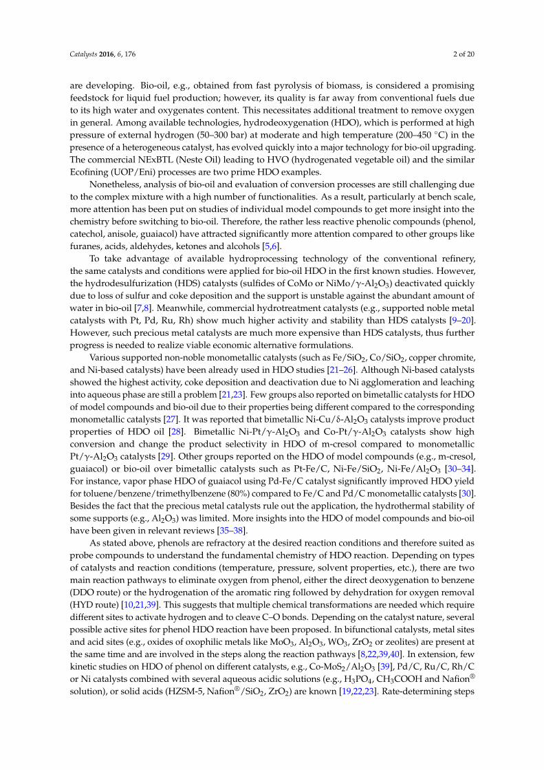
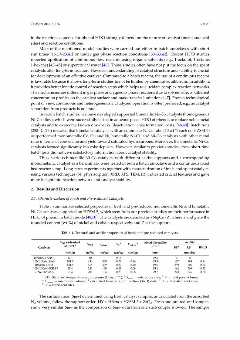
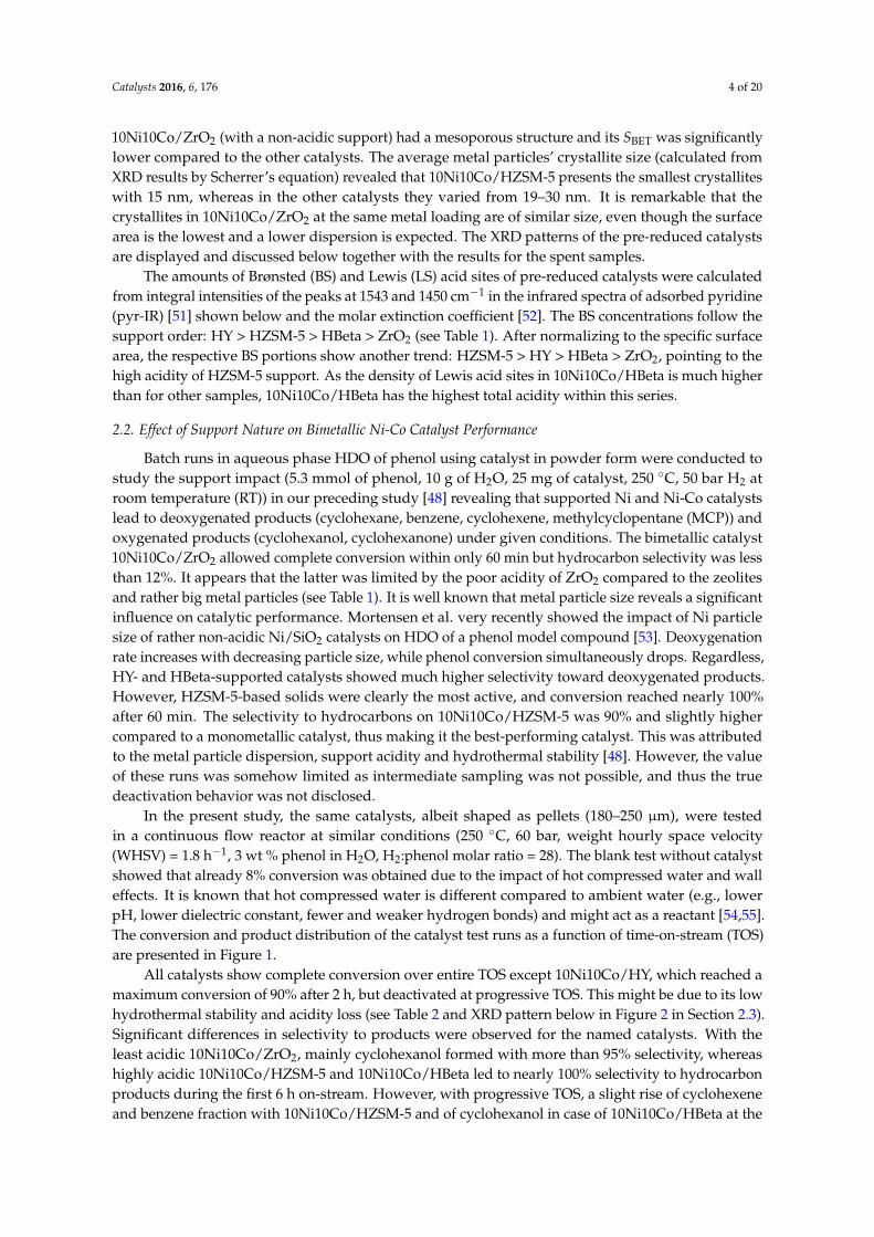
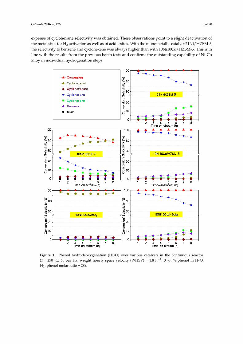
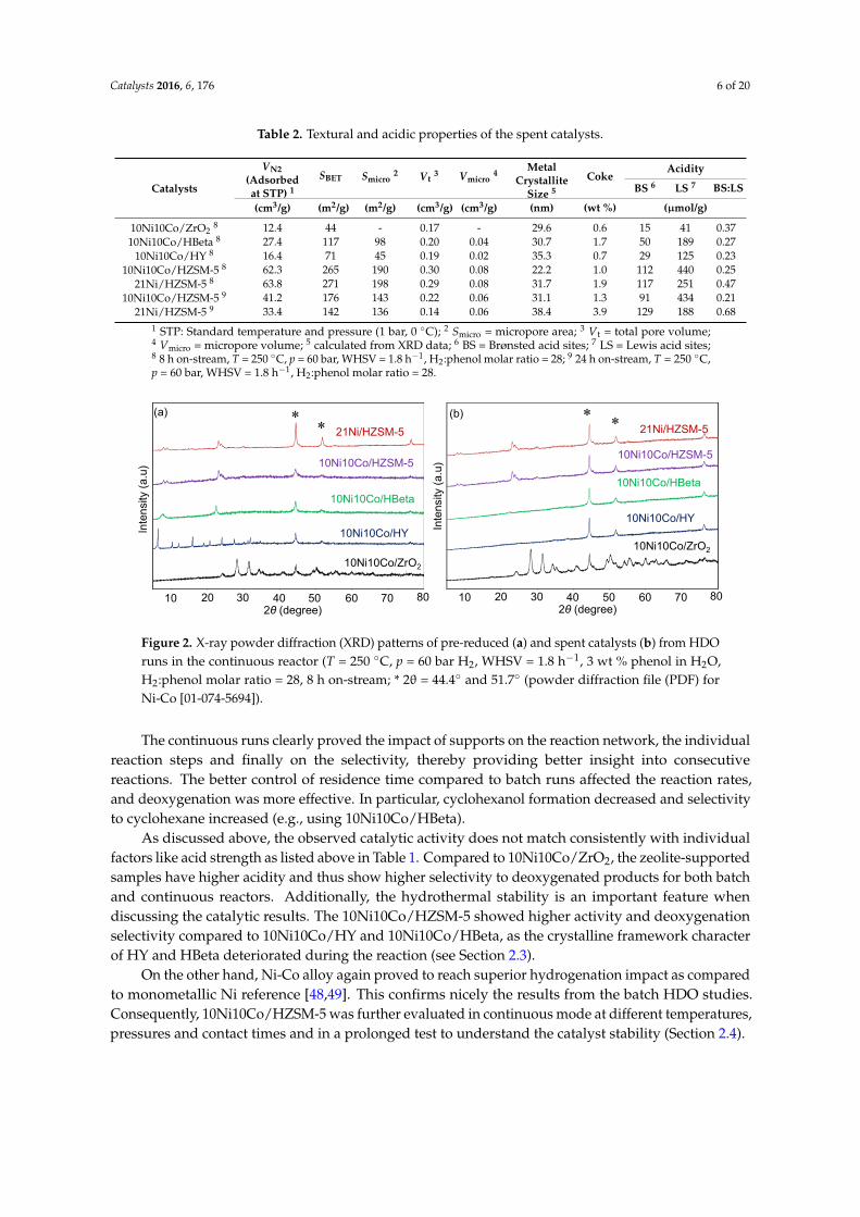
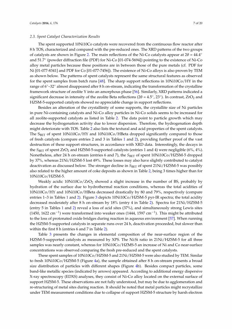
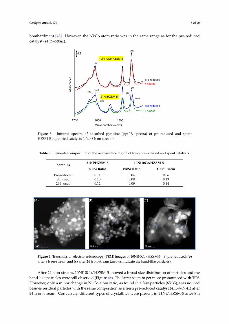
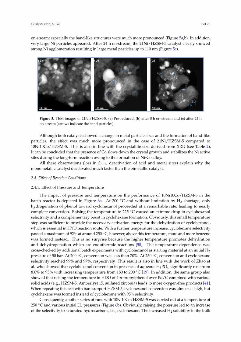
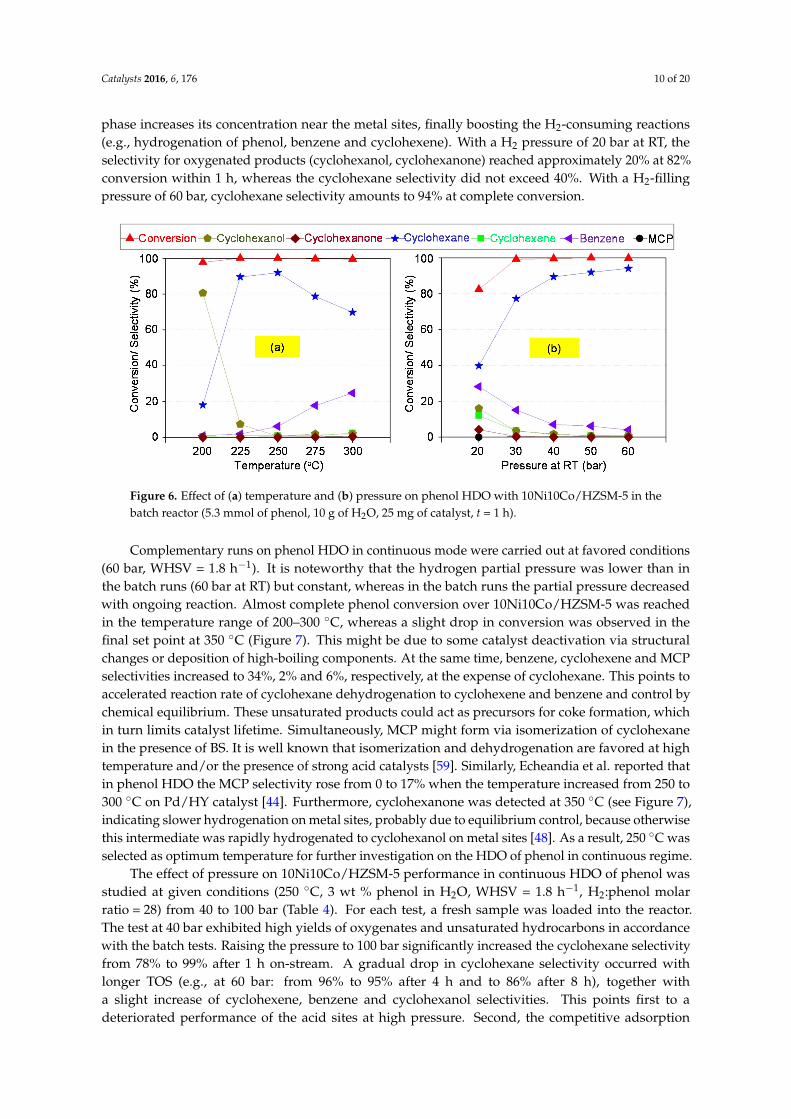
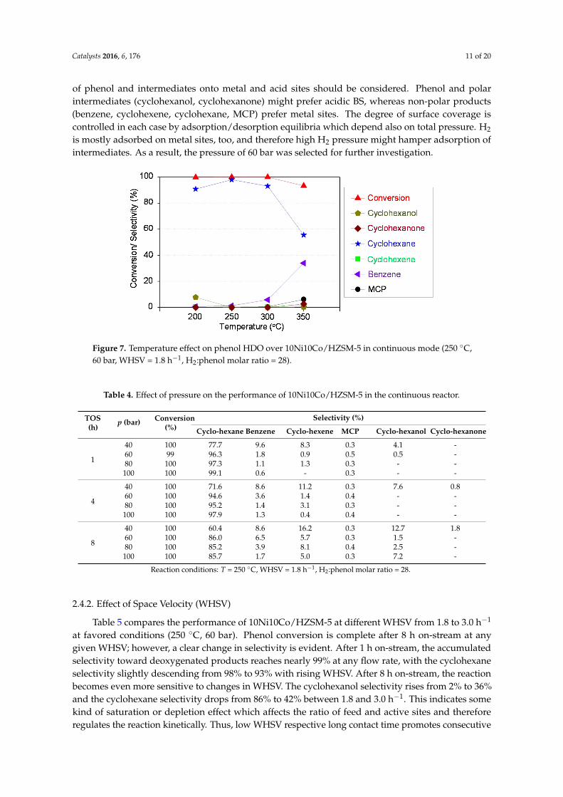
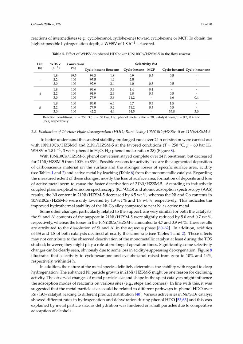
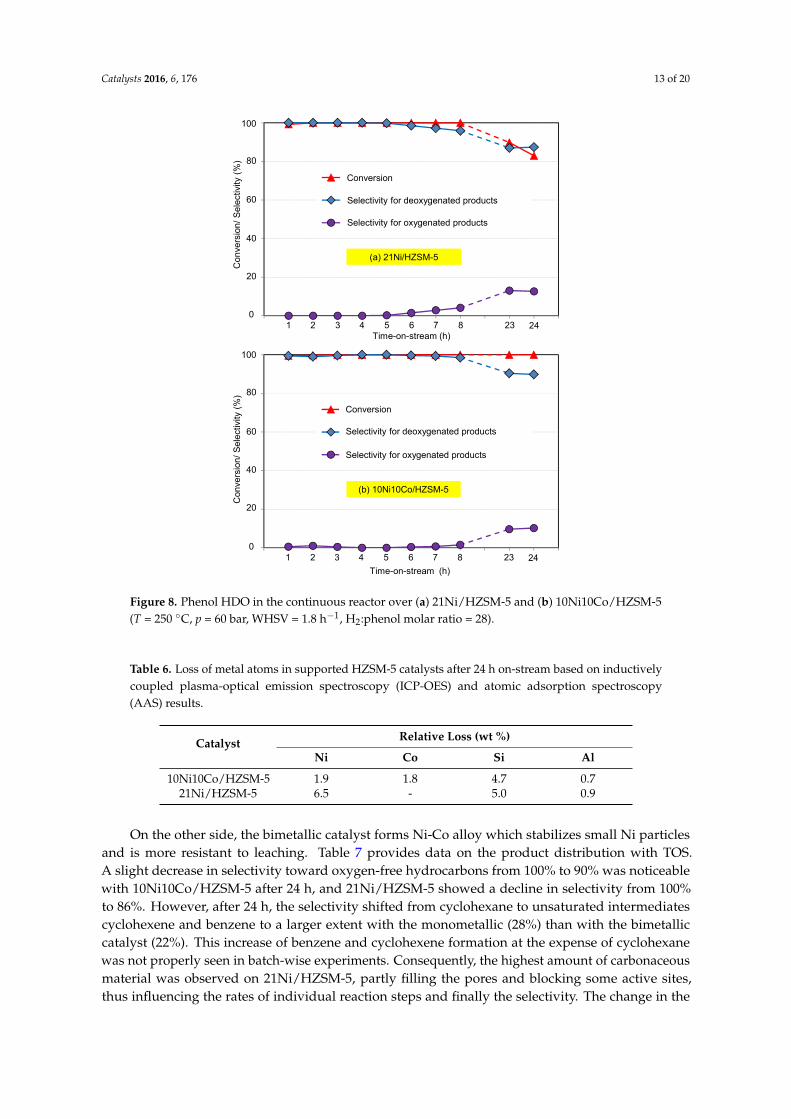
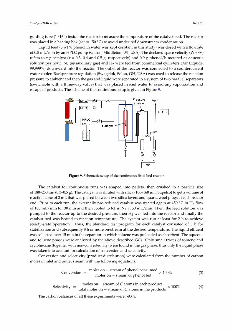


![Zeolite-Supported Ni Catalysts for CO2 Methanation: ect of ... · Common supports for CO2 methanation catalysts are oxides such as Al2O3, CeO2, ZrO2, TiO2 or SiO2, among others [9–12].](https://static.documents.pub/doc/80x56/613147fd1ecc51586944a30f/zeolite-supported-ni-catalysts-for-co2-methanation-ect-of-common-supports-for.jpg)


