Page 1
Supporting information
Effect of pore size distribution on iron oxide coated
granular activated carbons for phosphate adsorption –
Importance of mesoporesPrashanth Suresh Kumara,b, Thomas Prota, Leon Korvinga*, Karel J Keesman,a,c, Iulian Duguland, Mark C.M.
van Loosdrechtb, Geert-Jan Witkampb
aWetsus, European Centre Of Excellence for Sustainable Water Technology, Oostergoweg 9, 8911 MA,
Leeuwarden, The Netherlands
bDept. Biotechnology, Applied Sciences, Delft University of Technology, Building 58, Van der Maasweg 9,
2629 HZ Delft, The Netherlands
cBiobased chemistry and technology, Wageningen University, Bornse Weilanden 9,
6708 WG, Wageningen, The Netherlands
dFundamental Aspects of Materials and Energy Group, Delft University of Technology, Mekelweg 15 JB,
Delft, The Netherlands
*Corresponding author: [email protected] ; +31-58-2843160; Wetsus, European Centre Of
Excellence for Sustainable Water Technology, Oostergoweg 7, 8911 MA, Leeuwarden, The Netherlands
Page 2
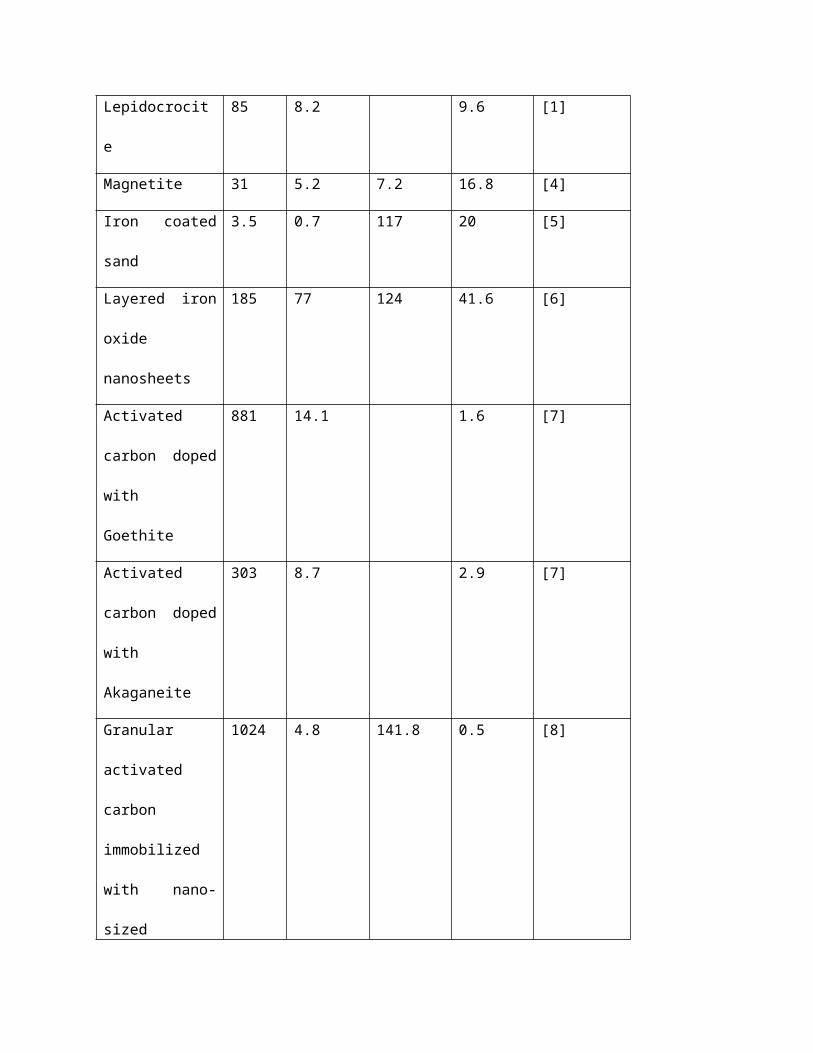
Table S1: Maximum phosphate adsorption capacity of different iron oxide based adsorbents (Although
conditions like pH, temperature, phosphate concentration and adsorbent concentration differ in these
studies, we expect the adsorbent constituent to be the significant factor for the variation in adsorption)
Adsorbent BET
surface
area
(m2/g)
Adsorption
capacity
(mg P/g
adsorbent)
Adsorption
capacity
(mg P/g
Fe)
Adsorption
capacity
(mg P/100
m2
adsorbent)
Ref
Akaganeite 94 13.9 [1]
Ferrihydrite 264 42.7 85.4 16.2 [2]
Goethite 76 6.4 10.6 8.4 [2]
Goethite 63 8.2 13 [1]
Granular ferric
hydroxide
(Akaganeite)
280 23.3 48.5 8.3 [3]
Lepidocrocite 85 8.2 9.6 [1]
Magnetite 31 5.2 7.2 16.8 [4]
Iron coated sand 3.5 0.7 117 20 [5]
Layered iron oxide
nanosheets
185 77 124 41.6 [6]
Activated carbon
doped with
Goethite
881 14.1 1.6 [7]
Page 3
Activated carbon
doped with
Akaganeite
303 8.7 2.9 [7]
Granular activated
carbon
immobilized with
nano-sized
magnetite
1024 4.8 141.8 0.5 [8]
Table S2: Effect of different oxidizing agents
Oxidizing agent Oxygen (wt %) Iron (wt %) Iron/Oxygen
added (molar
ratio)
None 4.23 0 -
HNO3 8.38 0.76 0.05
KMnO4 17.01 5.28 0.12
HClO4 7.17 0.38 0.04
H2O2 5.35 0.17 0.04
The oxygen content is shown for the GAC-2 and oxidized GAC-2 before the treatment with iron. The
iron content is shown for the corresponding Fe-GAC after treatment with iron solution.
Page 4
Table S3: General characteristics of the different GAC’s evaluated
Supplier
BET Surface area
(m2/g)
Average size
(mm) Shape Denoted as
Norit 1616 4 x 2 Cylindrical GAC-1
Desotec 927 2 Granular GAC-2
Mast carbon 1307 4 Granular GAC-3
Mast carbon 982 5 x 2 Cylindrical GAC-4
Mast carbon 908 5 Granular GAC-5
Table S4: Surface area of different samples as calculated using NLDFT model
Sample Total pore area (m2/g)
Microporous area(m2/g)
Mesoporous area(m2/g)
GAC-1 1338 1284 54GAC-2 843 764 79 GAC-3 1365 1329 36 GAC-4 1278 1278 0GAC-5 1094 1094 0Fe-GAC-1 770 729 41, 12*Fe-GAC-2 381 327 54, 30*Fe-GAC-3 832 765 67, 55*
*Indicates the mesoporous area above pore cut-off of 3nm
Page 5
Table S5: Surface area of different samples as calculated by BJH model
Sample Total pore area
(m2/g)*
Macroporous area
(m2/g)†
GAC-1 51.8 0.6
GAC-2 109.6 1.3
GAC-3 79.9 8.4
Fe-GAC-1 59 0.3
Fe-GAC-2 87.2 0.4
Fe-GAC-3 118.8 11.2
*Total pore area – It must be noted that the BJH model is not able to describe the microporous area and
hence the total pore area is much lower than that estimated by NLDFT model.
†Macroporous area (Since cutoff values from exactly 50 nm were not available, the closest available
average pore diameters were considered. For GAC-3 and Fe-GAC-3 this was around 40 nm. For all other
samples this was around 44 nm).
Table S6: Rate constants from pseudo-second order kinetic model
Sample qe (mg P/g) -
experimental
qe (mg P/g) - fitted k (g/mg min)
Fe-GAC-1 4.5 ± 0.1 4.6 ± 0.3 4 x 10⁻⁴ ± 1 x 10⁻⁴
Fe-GAC-2 6.2 ± 0.1 6.5 ± 0.4 2.8 x 10⁻⁴ ± 7 x 10⁻⁵
Page 6
Fe-GAC-3 7.2 ± 0.1 7.1 ± 8.8 x 10⁻⁴ ± 9 x 10⁻⁵
The pseudo second order kinetic model is described by the following equation:
q t=(k qe
2t)(1+(k qe t))
where,
qt is the adsorption capacity at time t,
k is the rate constant of adsorption (g/mg min),
qe is the adsorption capacity at equilibrium.
The pseudo-second order kinetic model predicts the adsorption capacity when equilibrium is reached as
indicated by the fitted adsorption capacities in table S3. The difference between the fitted and
experimental adsorption capacities after 4 days were less than 5 %.This shows that the experimental
conditions had reached close to equilibrium by 4 days.
Page 7
Fig S1: Incremental PSD of different GACs in terms of the pore area using (a) BJH model, (c) NLDFT
model. Cumulative PSDs of different GACs in term of the pore area using (b) BJH model, (d) NLDFT
model.
Page 8
Fig S2: Adsorption kinetics of the Fe-GACs . Dashed lines represent the pseudo second order kinetic
model fit. (Initial phosphate concentration = 20 mg P/L, Adsorbent concentration = 2 g/L, pH ≈6.5)
Fig S3: XRD spectra of (a) GAC-3 oxidized with KMnO4 (b) Fe-GAC (GAC-3 with highest iron loading)
Page 9
Text S1: Surface area covered by monolayer coating
The monolayer coverage on the GAC surface has been estimated for 3 different scenarios as depicted in
the following schematic:
The surface coverage was estimated by the following formula
AFe=
AunitV unit
∗CFe
ρunit XFe /Fe xO y
Where:
AFe = Area coated by Fe per gram of adsorbent (m2/g)
Aunit = Surface area covered by a unit particle (m2/particle)
Vunit = Volume of a unit particle
ρunit = density of a unit particle (g/m3, 5,18 g/m3 for Fe3O4 [9])
Page 10
CFe = Iron content of the Fe coated adsorbent (g Fe/g adsorbent)
XFe/FexOy = mass fraction of Fe in a certain iron oxide (0.72 g/g for Fe3O4)
(a) For spherical magnetite (Fe3O4) particle of diameter 4 nm,
Cross sectional area (m2) = 1.25 x 10⁻¹⁷,
Volume (cm3) = 3.35 x 10⁻²⁰,
Thereby, area coated by 34 mg Fe / g adsorbent = 3.40 m2/ g adsorbent
(b) If the 4 nm magnetite particle were cuboid shaped (assuming length 4 nm, width 1 nm and
height 1 nm), the area coated by 34 mg Fe is estimated in a similar way to be 9.07 m2/g
(c) If we consider coverage by unit cells of magnetite (cubic structure),
Length of unit cell (nm) = 0.84 (as mentioned in [9])
Cross sectional area (m2) = 7.05 x 10⁻¹⁹,
Volume (cm3) = 5.92 x 10⁻²²,
Using the above formula, area coated by 34 mg of Fe (m2) = 10.80 m2/g
Text S2: Sensitivity matrix
Let us consider the Langmuir model that was fitted to the adsorption data. The Langmuir equation is
given by:
Page 11
qe=qmK L/ (1+KLC e)
Where, qm and KL are the model parameters that will be estimated from the data and qe is the model
output. The predicted model output (q̂e) is determined by substituting the Ce values from the
experiment and replacing the parameters by the parameter estimates (θ̂).
In this case, the sensitivity matrix (X) is an n x 2 matrix with rows:
X i :=[(∂qe ,i /∂qm)(∂qe ,i/∂ KL)], for i = 1, 2,…n
Where,
(∂qe, i /∂qm)=1−1/(C e, iK L+1) ,
(∂qe, i /∂K L)=(C e, iqm)/(Ce, iK L+1)2 ,
After substituting the parameter estimates (q̂m and K̂ L) and the measured Ce values (n in total), the
sensitivity matrix X(θ̂) is obtained which is used in the calculation of the covariance matrix. In this case,
the covariance matrix is a 2 x2 matrix where the square root of the diagonal elements give the standard
deviations of the estimated parameters (q̂m and K̂ L), respectively.
1. References[1] J. Kim, W. Li, B.L. Philips, C.P. Grey, Phosphate adsorption on the iron oxyhydroxides goethite ([small
alpha]-FeOOH), akaganeite ([small beta]-FeOOH), and lepidocrocite ([gamma]-FeOOH): a 31P NMR
Study, Energy & Environmental Science 4 (2011) 4298-4305.
[2] O.K. Borggaard, B. Raben-Lange, A.L. Gimsing, B.W. Strobel, Influence of humic substances on
phosphate adsorption by aluminium and iron oxides, Geoderma 127 (2005) 270-279.
Page 12
[3] A. Genz, A. Kornmüller, M. Jekel, Advanced phosphorus removal from membrane filtrates by
adsorption on activated aluminium oxide and granulated ferric hydroxide, Water Research 38 (2004)
3523-3530.
[4] T.J. Daou, S. Begin-Colin, J.M. Grenèche, F. Thomas, A. Derory, P. Bernhardt, P. Legaré, G. Pourroy,
Phosphate Adsorption Properties of Magnetite-Based Nanoparticles, Chemistry of Materials 19 (2007)
4494-4505.
[5] Y. Huang, J.-K. Yang, A.A. Keller, Removal of Arsenic and Phosphate from Aqueous Solution by Metal
(Hydr-)oxide Coated Sand, ACS Sustainable Chemistry & Engineering 2 (2014) 1128-1138.
[6] L. Fang, L. Huang, P.E. Holm, X. Yang, H.C.B. Hansen, D. Wang, Facile upscaled synthesis of layered
iron oxide nanosheets and their application in phosphate removal, Journal of Materials Chemistry A 3
(2015) 7505-7512.
[7] Z. Wang, E. Nie, J. Li, M. Yang, Y. Zhao, X. Luo, Z. Zheng, Equilibrium and kinetics of adsorption of
phosphate onto iron-doped activated carbon, Environmental Science and Pollution Research 19 (2012)
2908-2917.
[8] A. Zach-Maor, R. Semiat, H. Shemer, Synthesis, performance, and modeling of immobilized nano-
sized magnetite layer for phosphate removal, Journal of Colloid and Interface Science 357 (2011) 440-
446.
[9] R.M. Cornell, U. Schwertmann, Introduction to the Iron Oxides, The Iron Oxides, Wiley-VCH Verlag
GmbH & Co. KGaA2004, pp. 1-7.