61
SUREFLOW™ FACE VELOCITY CONTROLLER MODEL 8650 OPERATION AND SERVICE MANUAL P/N 1980117, REVISION P FEBRUARY 2013
SUREFLOW™ FACE VELOCITY CONTROLLER
MODEL 8650
OPERATION AND SERVICE MANUAL
P/N 1980117, REVISION P FEBRUARY 2013

ii
SUREFLOW™ FACE VELOCITY CONTROLLER
MODEL 8650
OPERATION AND SERVICE MANUAL
P/N 1980117, REVISION P FEBRUARY 2013
U.S. AND CANADA OTHER COUNTRIES Sales & Customer Service: Sales & Customer Service: (800) 874-2811/(651) 490-2811 (001 651) 490-2811 Fax: Fax: (651) 490-3824 (001 651) 490-3824
SHIP/MAIL TO: E-MAIL TSI Incorporated [email protected] ATTN: Customer Service
500 Cardigan Road WEB SITE Shoreview, MN 55126 www.tsi.com USA
ii
Copyright TSI Incorporated / 1995–2013 / All rights reserved.
Part number 1980117 / Revision P / February 2013
LIMITATION OF WARRANTY AND LIABILITY (effective June 2011)
(For country-specific terms and conditions outside of the USA, please visit www.tsi.com.)
Seller warrants the goods sold hereunder, under normal use and service as described in the operator's manual, shall be free from defects in workmanship and material for twenty-four (24) months, or if less, the length of time specified in the operator's manual, from the date of shipment to the customer. This warranty period is inclusive of any statutory warranty. This limited warranty is subject to the following exclusions and exceptions:
a. Hot-wire or hot-film sensors used with research anemometers, and certain other components when indicated in specifications, are warranted for 90 days from the date of shipment;
b. Pumps are warranted for one year or 3000 hours; whichever comes first;
c. Parts repaired or replaced as a result of repair services are warranted to be free from defects in workmanship and material, under normal use, for 90 days from the date of shipment;
d. Seller does not provide any warranty on finished goods manufactured by others or on any fuses, batteries or other consumable materials. Only the original manufacturer's warranty applies;
e. Unless specifically authorized in a separate writing by Seller, Seller makes no warranty with respect to, and shall have no liability in connection with, goods which are incorporated into other products or equipment, or which are modified by any person other than Seller.
The foregoing is IN LIEU OF all other warranties and is subject to the LIMITATIONS stated herein. NO OTHER
EXPRESS OR IMPLIED WARRANTY OF FITNESS FOR PARTICULAR PURPOSE OR MERCHANTABILITY
IS MADE. WITH RESPECT TO SELLER’S BREACH OF THE IMPLIED WARRANTY AGAINST
INFRINGEMENT, SAID WARRANTY IS LIMITED TO CLAIMS OF DIRECT INFRINGEMENT AND
EXCLUDES CLAIMS OF CONTRIBUTORY OR INDUCED INFRINGEMENTS. BUYER’S EXCLUSIVE
REMEDY SHALL BE THE RETURN OF THE PURCHASE PRICE DISCOUNTED FOR REASONABLE WEAR
AND TEAR OR AT SELLER’S OPTION REPLACEMENT OF THE GOODS WITH NON-INFRINGING
GOODS.
TO THE EXTENT PERMITTED BY LAW, THE EXCLUSIVE REMEDY OF THE USER OR BUYER, AND THE LIMIT OF SELLER'S LIABILITY FOR ANY AND ALL LOSSES, INJURIES, OR DAMAGES CONCERNING THE GOODS (INCLUDING CLAIMS BASED ON CONTRACT, NEGLIGENCE, TORT, STRICT LIABILITY OR OTHERWISE) SHALL BE THE RETURN OF GOODS TO SELLER AND THE REFUND OF THE PURCHASE PRICE, OR, AT THE OPTION OF SELLER, THE REPAIR OR REPLACEMENT OF THE GOODS. IN THE CASE OF SOFTWARE, SELLER WILL REPAIR OR REPLACE DEFECTIVE SOFTWARE OR IF UNABLE TO DO SO, WILL REFUND THE PURCHASE PRICE OF THE SOFTWARE. IN NO EVENT SHALL SELLER BE LIABLE FOR LOST PROFITS OR ANY SPECIAL, CONSEQUENTIAL OR INCIDENTAL DAMAGES. SELLER SHALL NOT BE RESPONSIBLE FOR INSTALLATION, DISMANTLING OR REINSTALLATION COSTS OR CHARGES. No Action, regardless of form, may be brought against Seller more than 12 months after a cause of action has accrued. The goods returned under warranty to Seller's factory shall be at Buyer's risk of loss, and will be returned, if at all, at Seller's risk of loss.
Buyer and all users are deemed to have accepted this LIMITATION OF WARRANTY AND LIABILITY, which contains the complete and exclusive limited warranty of Seller. This LIMITATION OF WARRANTY AND LIABILITY may not be amended, modified or its terms waived, except by writing signed by an Officer of Seller.
SERVICE POLICY Knowing that inoperative or defective instruments are as detrimental to TSI as they are to our customers, our service policy is designed to give prompt attention to any problems. If any malfunction is discovered, please contact your nearest sales office or representative, or call TSI's Customer Service department at (800) 874-2811 or (651) 490-2811.
TRADEMARKS SureFlow is a trademark of TSI Incorporated.
iii
CONTENTS
HOW TO USE THIS MANUAL ..................................................................................................... IV
PART ONE ..................................................................................................................................... 1
User Basics .......................................................................................................... 1 The Instrument ..................................................................................................... 1 Operator Panel ..................................................................................................... 2 Alarms................................................................................................................... 4 Before Calling TSI ................................................................................................ 5
PART TWO ..................................................................................................................................... 7
Technical Section ................................................................................................. 7 Software Programming ......................................................................................... 8 Menu and Menu Items ........................................................................................ 12 Calibration .......................................................................................................... 22 Optimizing Controller Performance .................................................................... 23 Maintenance and Repair Parts ........................................................................... 24 Troubleshooting Section ..................................................................................... 25
APPENDIX A ................................................................................................................................ 37
Specifications ..................................................................................................... 37
APPENDIX B ................................................................................................................................ 39
Network Communications .................................................................................. 39 Modbus Communications ................................................................................... 39 N2 Communications Description of Variables ................................................... 42 LonWorks Node Object ...................................................................................... 44 LonWorks Object ................................................................................................ 45 8650 BACnet MS/TP Protocol Implementation Conformance Statement .......... 46 BACnet MS/TP Object Set ................................................................................. 48
APPENDIX C ................................................................................................................................ 49
Wiring Information .............................................................................................. 49
APPENDIX D ................................................................................................................................ 53
Access Codes ..................................................................................................... 53
iv
How to Use This Manual The SureFlow™ Operation and Service Manual describes how to operate, configure, calibrate, maintain and troubleshoot the Model 8650 SureFlow Face Velocity Controller. The manual is divided into two parts. Part one describes the SureFlow unit and how to interface with the device. This section should be read by users, facilities staff, and anyone who requires a basic understanding of how the device operates. Part two describes the technical aspects of the product which include operation, configuration, calibration, maintenance and troubleshooting. Part two should be read by personnel programming or maintaining the unit. TSI recommends thoroughly reading this manual before changing any software items.
NOTE: This operation and service manual assumes that the SureFlow controller has been properly installed. Refer to the Installation Instructions if there is any question as to whether the SureFlow controller has been installed properly.
User Basics 1
Part One
User Basics This section is designed to provide a brief but thorough overview of the SureFlow product installed. These few pages explain the purpose (The Instrument) and the operation (Useful user information, Operator panel, Alarms) of the product. Technical product information is available in Part Two of the manual.
The Instrument
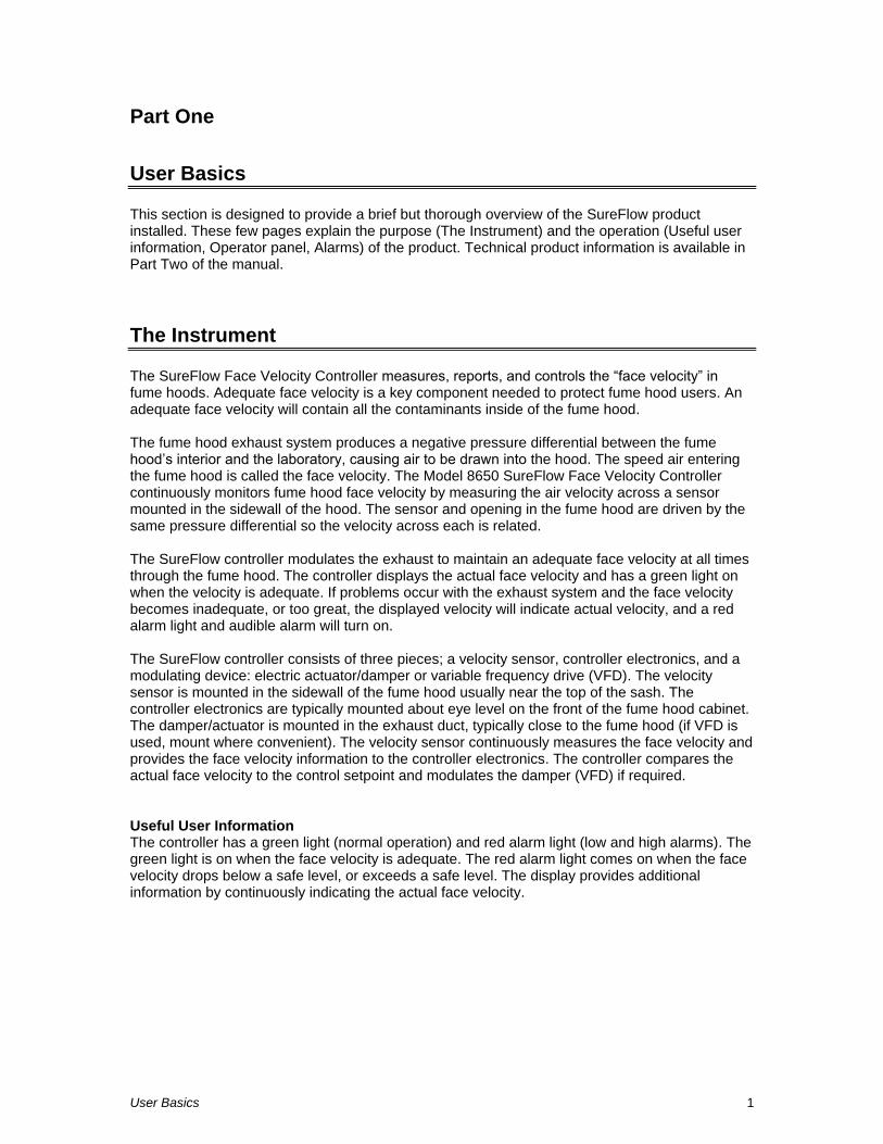
The SureFlow Face Velocity Controller measures, reports, and controls the ―face velocity‖ in fume hoods. Adequate face velocity is a key component needed to protect fume hood users. An adequate face velocity will contain all the contaminants inside of the fume hood. The fume hood exhaust system produces a negative pressure differential between the fume hood’s interior and the laboratory, causing air to be drawn into the hood. The speed air entering the fume hood is called the face velocity. The Model 8650 SureFlow Face Velocity Controller continuously monitors fume hood face velocity by measuring the air velocity across a sensor mounted in the sidewall of the hood. The sensor and opening in the fume hood are driven by the same pressure differential so the velocity across each is related. The SureFlow controller modulates the exhaust to maintain an adequate face velocity at all times through the fume hood. The controller displays the actual face velocity and has a green light on when the velocity is adequate. If problems occur with the exhaust system and the face velocity becomes inadequate, or too great, the displayed velocity will indicate actual velocity, and a red alarm light and audible alarm will turn on. The SureFlow controller consists of three pieces; a velocity sensor, controller electronics, and a modulating device: electric actuator/damper or variable frequency drive (VFD). The velocity sensor is mounted in the sidewall of the fume hood usually near the top of the sash. The controller electronics are typically mounted about eye level on the front of the fume hood cabinet. The damper/actuator is mounted in the exhaust duct, typically close to the fume hood (if VFD is used, mount where convenient). The velocity sensor continuously measures the face velocity and provides the face velocity information to the controller electronics. The controller compares the actual face velocity to the control setpoint and modulates the damper (VFD) if required.
Useful User Information The controller has a green light (normal operation) and red alarm light (low and high alarms). The green light is on when the face velocity is adequate. The red alarm light comes on when the face velocity drops below a safe level, or exceeds a safe level. The display provides additional information by continuously indicating the actual face velocity.
Part One 2
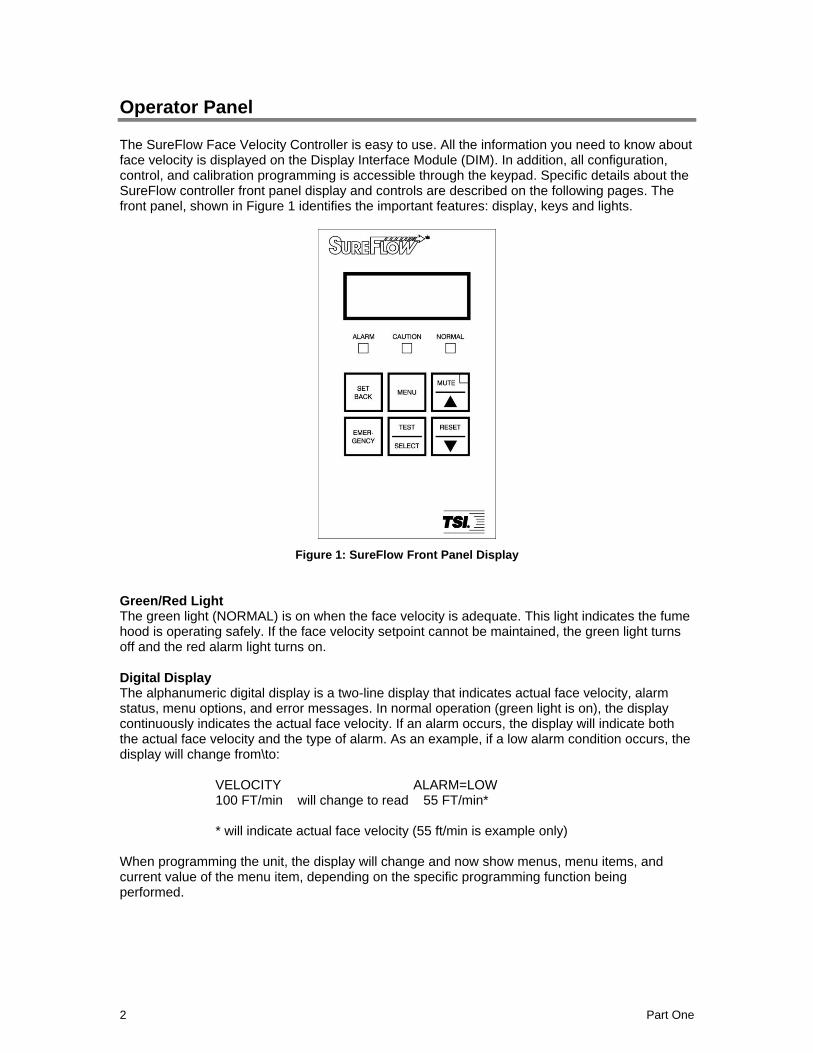
Operator Panel The SureFlow Face Velocity Controller is easy to use. All the information you need to know about face velocity is displayed on the Display Interface Module (DIM). In addition, all configuration, control, and calibration programming is accessible through the keypad. Specific details about the SureFlow controller front panel display and controls are described on the following pages. The front panel, shown in Figure 1 identifies the important features: display, keys and lights.
Figure 1: SureFlow Front Panel Display
Green/Red Light The green light (NORMAL) is on when the face velocity is adequate. This light indicates the fume hood is operating safely. If the face velocity setpoint cannot be maintained, the green light turns off and the red alarm light turns on.
Digital Display The alphanumeric digital display is a two-line display that indicates actual face velocity, alarm status, menu options, and error messages. In normal operation (green light is on), the display continuously indicates the actual face velocity. If an alarm occurs, the display will indicate both the actual face velocity and the type of alarm. As an example, if a low alarm condition occurs, the display will change from\to: VELOCITY ALARM=LOW 100 FT/min will change to read 55 FT/min* * will indicate actual face velocity (55 ft/min is example only) When programming the unit, the display will change and now show menus, menu items, and current value of the menu item, depending on the specific programming function being performed.
User Basics 3
Keypad The keypad has six keys. The gray keys with black letters (4 keys) are user information keys. In normal operation these keys are active. Additionally, the red emergency key is active. The gray keys with blue characters (4 keys) are used to program the unit. A thorough description of each key is given below.
User Keys - Gray with Black Letters The four keys with black letters provide information without changing the operation or the function of the unit.
TEST key
The TEST key initiates an instrument self-test. Pressing the TEST key activates a scrolling sequence on the display that shows the product model number, software version, and all setpoint and alarm values. The unit then performs a self-test that tests the display, indicator lights, audible alarm, and internal electronics to ensure they are operating properly. If a problem with the unit exists, DATA ERROR will be displayed. You should have qualified personnel determine the problem with the unit.
RESET key
The RESET key performs three functions. 1) Resets the alarm light, alarm contacts, and audible alarm when in a latched or non-automatic reset mode. The face velocity must be
in the safe or normal range before the RESET key will operate. 2) Resets the emergency function after the emergency key has been pressed (see EMERGENCY key). 3) Clears any displayed error messages.
MUTE key
The MUTE key temporarily silences an audible alarm. Pressing the MUTE key once temporarily silences the audible alarm. The alarm remains silent until the unit returns to
control setpoint. Pressing the MUTE key twice, when controller is in alarm, will turn the yellow mute light on and permanently silence the audible alarm.
NOTE: You can program the unit so that the audible alarm cannot be permanently turned off (see menu item AUD DISABLE).
SETBACK key
The SETBACK key activates the setback or second setpoint face velocity. In setback mode, the controller controls at the setback setpoint, the display indicates SETBACK,
and the yellow light (CAUTION) turns on. If the SETBACK key is pressed when the unit is in setback mode, the controller returns to normal control setpoint.
Programming Keys - Gray with Blue Characters The four keys with blue print are used to program or configure the unit to fit a particular application.
WARNING: Pressing these keys will change how the unit functions, so please thoroughly review the manual before changing menu items.
MENU key
The MENU key performs three functions. 1) Provides access to the menus when in the
normal operating mode. 2) When the unit is being programmed, the MENU key acts as an escape key to remove you from an item or menu, without saving data. 3) Returns the
unit to the normal operating mode. The MENU key is further described in the Software Programming section of this manual.
Part One 4
SELECT key
The SELECT key performs three functions. 1) Provides access to specific menus.
2) Provides access to menu items. 3) Saves data. Pressing the SELECT key when finished with a menu item will save the data, and exit you out of the menu item.
/ keys
The / keys are used to scroll through the menus, menu items, and through the range of item values that can be selected. Depending on the item type the values may be numerical, specific properties (on/off), or a bar graph.
Emergency Key - Red with Black Letters
EMERGENCY key
The red EMERGENCY key puts the controller into emergency mode. The controller maximizes the face velocity by modulating the damper full open (VFD to maximum).
Pressing the EMERGENCY key will cause the display to flash ‖EMERGENCY‖, the red alarm light to flash on and off, and the audible alarm to beep intermittently. To return to
control mode press the EMERGENCY key or the RESET key.
Alarms SureFlow controller has visual (red light) and audible alarms to inform you of changing fume hood conditions. The alarm levels (setpoints) are determined by facilities staff, which could be Engineering, Industrial Hygiene, or a facilities group depending on how the safety staff is organized. The alarms, audible and visual, will activate whenever the preset alarm level is reached. The alarms will activate if the face velocity is low or inadequate, high or too great, or when the exhaust airflow is insufficient (need optional flow station installed). When the fume hood is operating safely, no alarms will sound. Example: The low alarm is preset to activate when the face velocity falls below 60 ft/min. When
the face velocity drops below 60 ft/min, the audible and visual alarms activate. The alarms turn off (when set to unlatched) when the unit returns to the safe range, which is defined as 20 ft/min greater than alarm setpoint (80 ft/min).
Visual Alarm The red light on the front of the unit indicates an alarm condition. The red light is on for all alarm conditions, low alarms, high alarms, and emergency. The light is on continuously in a low or high alarm condition, and flashes in an emergency condition.
Audible Alarm - EMERGENCY key When the EMERGENCY key is pressed, the audible alarm beeps intermittently until the
EMERGENCY or RESET key is pressed terminating the emergency alarm. The emergency alarm
cannot be silenced by pressing the MUTE key.
Audible Alarms - All Except Emergency The audible alarm is continuously on in all low and high alarm conditions. The audible alarm can
be temporarily silenced by pressing the MUTE key once and permanently muted by pressing the
MUTE key twice (yellow mute light turns on).
User Basics 5
If the audible alarm has been temporarily muted (yellow mute light is off), the alarm is silent until the face velocity returns to the safe velocity range. The safe range is 20 ft/min above the low alarm setpoint and 20 ft/min below the high alarm setpoint. The controller automatically resets the alarm to sound again if another alarm occurs (see menu item ALARM RESET for options to turn alarms off). If the audible alarm is permanently muted (yellow mute light is on), the audible alarm
will remain off until the MUTE key is pressed (once). You can program the audible alarm so it cannot be permanently turned off (see menu item AUD DISABLE). The audible and visual alarms can be programmed to either automatically turn off when the unit
returns to the safe range or to stay in alarm until the RESET key is pressed (See menu item ALARM RESET).
Before Calling TSI
This manual should answer most questions and resolve most problems you may encounter. If you need assistance or further explanation, contact your local TSI representative or TSI. TSI is committed to providing high quality products backed by outstanding service. Please have the following information available prior to contacting your authorized TSI Manufacturer’s Representative or TSI: - Model number of unit* 8650-____ - Software revision level* - Facility where unit is installed
* First two items that scroll when TEST key is pressed. Due to the different SureFlow models available, the above information is needed to accurately answer your questions. For the name of your local TSI representative or to talk to TSI service personnel, please call TSI at:
U.S. AND CANADA OTHER COUNTRIES Sales & Customer Service: Sales & Customer Service: (800) 874-2811/(651) 490-2811 (001 651) 490-2811 Fax: Fax: (651) 490-3824 (001 651) 490-3824
E-MAIL TSI Incorporated [email protected] Attn: Customer Service
500 Cardigan Road WEB SITE Shoreview, MN 55126 www.tsi.com USA

Part One 6
(This page intentionally left blank)
Technical Section 7
Part Two
Technical Section
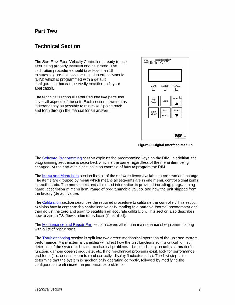
The SureFlow Face Velocity Controller is ready to use after being properly installed and calibrated. The calibration procedure should take less than 15 minutes. Figure 2 shows the Digital Interface Module (DIM) which is programmed with a default configuration that can be easily modified to fit your application. The technical section is separated into five parts that cover all aspects of the unit. Each section is written as independently as possible to minimize flipping back and forth through the manual for an answer.
Figure 2: Digital Interface Module
The Software Programming section explains the programming keys on the DIM. In addition, the programming sequence is described, which is the same regardless of the menu item being changed. At the end of this section is an example of how to program the DIM. The Menu and Menu Item section lists all of the software items available to program and change. The items are grouped by menu which means all setpoints are in one menu, control signal items in another, etc. The menu items and all related information is provided including; programming name, description of menu item, range of programmable values, and how the unit shipped from the factory (default value). The Calibration section describes the required procedure to calibrate the controller. This section explains how to compare the controller’s velocity reading to a portable thermal anemometer and then adjust the zero and span to establish an accurate calibration. This section also describes how to zero a TSI flow station transducer (if installed). The Maintenance and Repair Part section covers all routine maintenance of equipment, along with a list of repair parts. The Troubleshooting section is split into two areas: mechanical operation of the unit and system performance. Many external variables will affect how the unit functions so it is critical to first determine if the system is having mechanical problems—i.e., no display on unit, alarms don’t function, damper doesn’t modulate, etc. If no mechanical problems exist, look for performance problems (i.e., doesn’t seem to read correctly, display fluctuates, etc.). The first step is to determine that the system is mechanically operating correctly, followed by modifying the configuration to eliminate the performance problems.
Part Two 8
Software Programming Programming the SureFlow controller is quick and easy if the programming keys are understood, and the proper keystroke procedure is followed. The programming keys are defined first, followed by the required keystroke procedure. At the end of this section is a programming example.
NOTE: It is important to note that the unit is always operating (except when checking the CONTROL OUTPUT) when programming. When a menu item value is changed, the new
value takes effect immediately after saving the change, not when the unit returns to normal operating mode.
This section covers programming the instrument through the keypad and display. If programming through RS-485 communications, use the host computer’s procedure. The changes take place immediately upon saving data in the instrument.
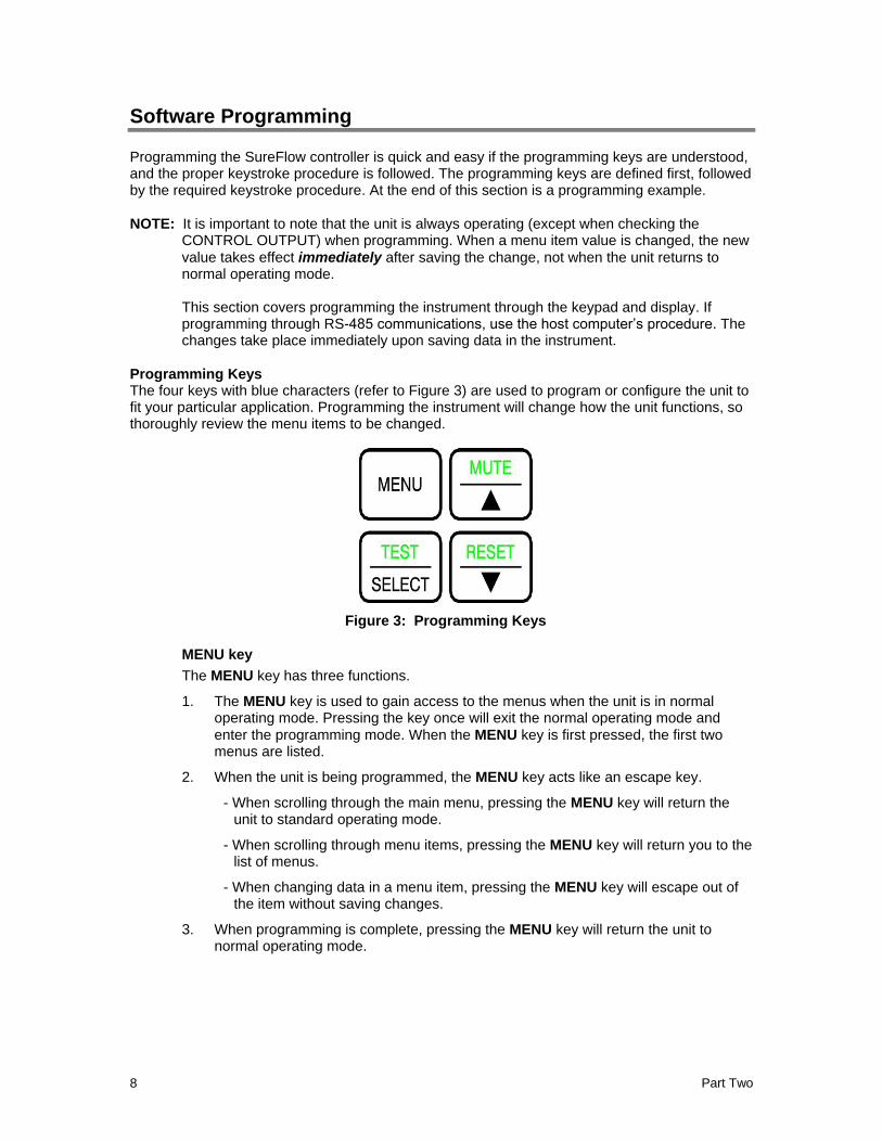
Programming Keys The four keys with blue characters (refer to Figure 3) are used to program or configure the unit to fit your particular application. Programming the instrument will change how the unit functions, so thoroughly review the menu items to be changed.
Figure 3: Programming Keys
MENU key
The MENU key has three functions.
1. The MENU key is used to gain access to the menus when the unit is in normal operating mode. Pressing the key once will exit the normal operating mode and
enter the programming mode. When the MENU key is first pressed, the first two menus are listed.
2. When the unit is being programmed, the MENU key acts like an escape key.
- When scrolling through the main menu, pressing the MENU key will return the unit to standard operating mode.
- When scrolling through menu items, pressing the MENU key will return you to the list of menus.
- When changing data in a menu item, pressing the MENU key will escape out of the item without saving changes.
3. When programming is complete, pressing the MENU key will return the unit to normal operating mode.
Technical Section 9
SELECT key
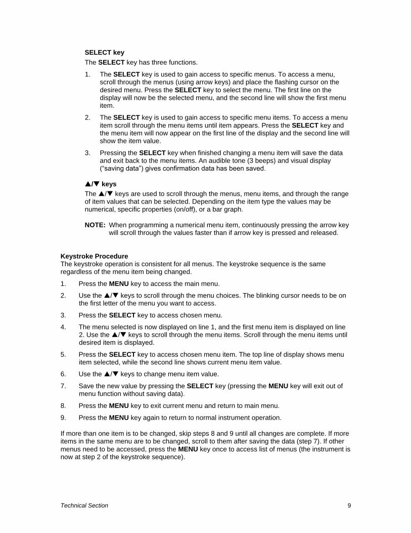
The SELECT key has three functions.
1. The SELECT key is used to gain access to specific menus. To access a menu, scroll through the menus (using arrow keys) and place the flashing cursor on the
desired menu. Press the SELECT key to select the menu. The first line on the display will now be the selected menu, and the second line will show the first menu item.
2. The SELECT key is used to gain access to specific menu items. To access a menu
item scroll through the menu items until item appears. Press the SELECT key and the menu item will now appear on the first line of the display and the second line will show the item value.
3. Pressing the SELECT key when finished changing a menu item will save the data and exit back to the menu items. An audible tone (3 beeps) and visual display (―saving data‖) gives confirmation data has been saved.
/ keys
The / keys are used to scroll through the menus, menu items, and through the range of item values that can be selected. Depending on the item type the values may be numerical, specific properties (on/off), or a bar graph.
NOTE: When programming a numerical menu item, continuously pressing the arrow key will scroll through the values faster than if arrow key is pressed and released.
Keystroke Procedure The keystroke operation is consistent for all menus. The keystroke sequence is the same regardless of the menu item being changed.
1. Press the MENU key to access the main menu.
2. Use the / keys to scroll through the menu choices. The blinking cursor needs to be on the first letter of the menu you want to access.
3. Press the SELECT key to access chosen menu.
4. The menu selected is now displayed on line 1, and the first menu item is displayed on line 2. Use the / keys to scroll through the menu items. Scroll through the menu items until desired item is displayed.
5. Press the SELECT key to access chosen menu item. The top line of display shows menu item selected, while the second line shows current menu item value.
6. Use the / keys to change menu item value.
7. Save the new value by pressing the SELECT key (pressing the MENU key will exit out of menu function without saving data).
8. Press the MENU key to exit current menu and return to main menu.
9. Press the MENU key again to return to normal instrument operation.
If more than one item is to be changed, skip steps 8 and 9 until all changes are complete. If more items in the same menu are to be changed, scroll to them after saving the data (step 7). If other
menus need to be accessed, press the MENU key once to access list of menus (the instrument is now at step 2 of the keystroke sequence).
Part Two 10
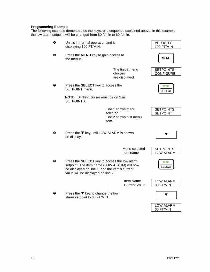
Programming Example The following example demonstrates the keystroke sequence explained above. In this example the low alarm setpoint will be changed from 80 ft/min to 60 ft/min.
Unit is in normal operation and is
displaying 100 FT/MIN. VELOCITY 100 FT/MIN
Press the MENU key to gain access to the menus.
The first 2 menu choices are displayed.
SETPOINTS CONFIGURE
Press the SELECT key to access the SETPOINT menu.
NOTE: Blinking cursor must be on S in SETPOINTS.
Line 1 shows menu selected. Line 2 shows first menu item.
SETPOINTS SETPOINT
Press the key until LOW ALARM is shown on display.
Menu selected Item name
SETPOINTS LOW ALARM
Press the SELECT key to access the low alarm setpoint. The item name (LOW ALARM) will now be displayed on line 1, and the item's current value will be displayed on line 2.
Item Name Current Value
LOW ALARM 80 FT/MIN
Press the key to change the low
alarm setpoint to 60 FT/MIN.
LOW ALARM
60 FT/MIN
Technical Section 11
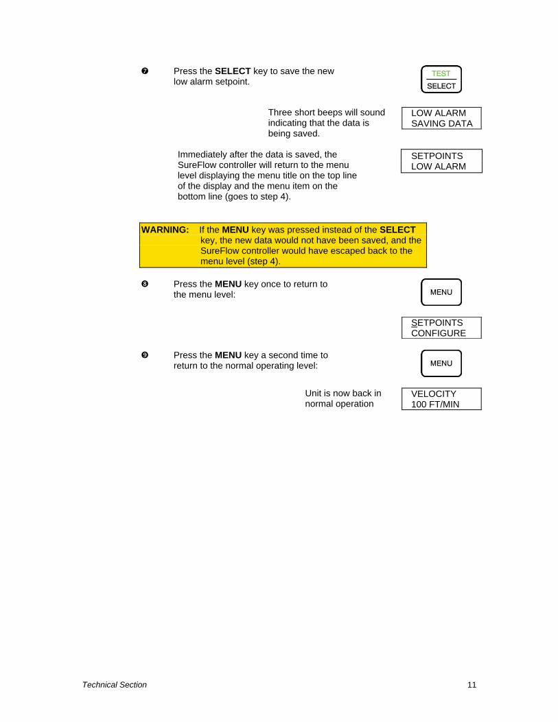
Press the SELECT key to save the new low alarm setpoint.
Three short beeps will sound indicating that the data is being saved.
LOW ALARM SAVING DATA
Immediately after the data is saved, the SureFlow controller will return to the menu level displaying the menu title on the top line of the display and the menu item on the bottom line (goes to step 4).
SETPOINTS LOW ALARM
WARNING: If the MENU key was pressed instead of the SELECT key, the new data would not have been saved, and the SureFlow controller would have escaped back to the menu level (step 4).
Press the MENU key once to return to the menu level:
SETPOINTS CONFIGURE
Press the MENU key a second time to return to the normal operating level:
Unit is now back in normal operation
VELOCITY 100 FT/MIN
Part Two 12
Menu and Menu Items The SureFlow controller is a very versatile device which can be configured to meet your specific application. This section lists all of the menu items available to program and change (except diagnostics menu). Changing any item is accomplished by using the keypad, or if communications are installed through the RS-485 Communications port. If you are unfamiliar with the keystroke procedure please see Software Programming section for a detailed explanation. This section provides the following information:
Complete list of menus and all menu items.
Gives the menu or programming name.
Defines each menu item’s function; what it does, how it does it, etc.
Gives the range of values that can be programmed.
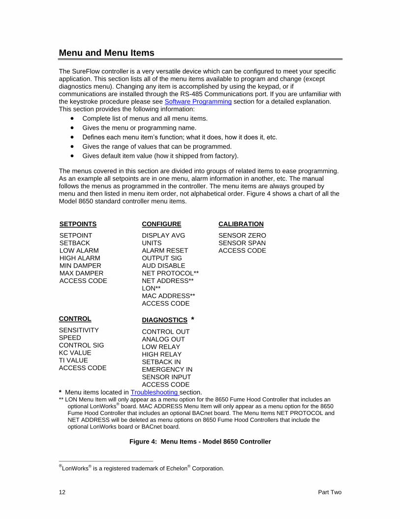
Gives default item value (how it shipped from factory). The menus covered in this section are divided into groups of related items to ease programming. As an example all setpoints are in one menu, alarm information in another, etc. The manual follows the menus as programmed in the controller. The menu items are always grouped by menu and then listed in menu item order, not alphabetical order. Figure 4 shows a chart of all the Model 8650 standard controller menu items.
SETPOINTS
SETPOINT SETBACK LOW ALARM HIGH ALARM MIN DAMPER MAX DAMPER ACCESS CODE
CONFIGURE
DISPLAY AVG UNITS ALARM RESET OUTPUT SIG AUD DISABLE NET PROTOCOL** NET ADDRESS** LON** MAC ADDRESS** ACCESS CODE
CALIBRATION
SENSOR ZERO SENSOR SPAN ACCESS CODE
CONTROL
SENSITIVITY SPEED CONTROL SIG KC VALUE TI VALUE ACCESS CODE
DIAGNOSTICS *
CONTROL OUT ANALOG OUT LOW RELAY HIGH RELAY SETBACK IN EMERGENCY IN SENSOR INPUT ACCESS CODE
* Menu items located in Troubleshooting section. ** LON Menu Item will only appear as a menu option for the 8650 Fume Hood Controller that includes an
optional LonWorks® board. MAC ADDRESS Menu Item will only appear as a menu option for the 8650
Fume Hood Controller that includes an optional BACnet board. The Menu Items NET PROTOCOL and NET ADDRESS will be deleted as menu options on 8650 Fume Hood Controllers that include the optional LonWorks board or BACnet board.
Figure 4: Menu Items - Model 8650 Controller
®LonWorks
® is a registered trademark of Echelon
® Corporation.
Te
chn
ical S
ectio
n
13
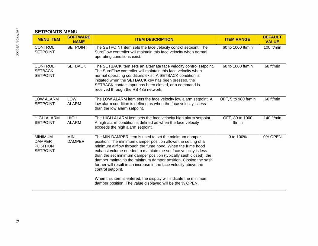
SETPOINTS MENU
MENU ITEMSOFTWARE
NAMEITEM DESCRIPTION ITEM RANGE
DEFAULT VALUE
CONTROL SETPOINT
SETPOINT The SETPOINT item sets the face velocity control setpoint. The SureFlow controller will maintain this face velocity when normal operating conditions exist.
60 to 1000 ft/min
100 ft/min
CONTROL SETBACK SETPOINT
SETBACK The SETBACK item sets an alternate face velocity control setpoint. The SureFlow controller will maintain this face velocity when normal operating conditions exist. A SETBACK condition is
initiated when the SETBACK key has been pressed, the SETBACK contact input has been closed, or a command is received through the RS 485 network.
60 to 1000 ft/min
60 ft/min
LOW ALARM SETPOINT
LOW ALARM
The LOW ALARM item sets the face velocity low alarm setpoint. A low alarm condition is defined as when the face velocity is less than the low alarm setpoint.
OFF, 5 to 980 ft/min
60 ft/min
HIGH ALARM SETPOINT
HIGH ALARM
The HIGH ALARM item sets the face velocity high alarm setpoint. A high alarm condition is defined as when the face velocity exceeds the high alarm setpoint.
OFF, 80 to 1000 ft/min
140 ft/min
MINIMUM DAMPER POSITION SETPOINT
MIN DAMPER
The MIN DAMPER item is used to set the minimum damper position. The minimum damper position allows the setting of a minimum airflow through the fume hood. When the fume hood exhaust volume needed to maintain the set face velocity is less than the set minimum damper position (typically sash closed), the damper maintains the minimum damper position. Closing the sash further will result in an increase in the face velocity above the control setpoint. When this item is entered, the display will indicate the minimum damper position. The value displayed will be the % OPEN.
0 to 100% 0% OPEN
14
Part T
wo
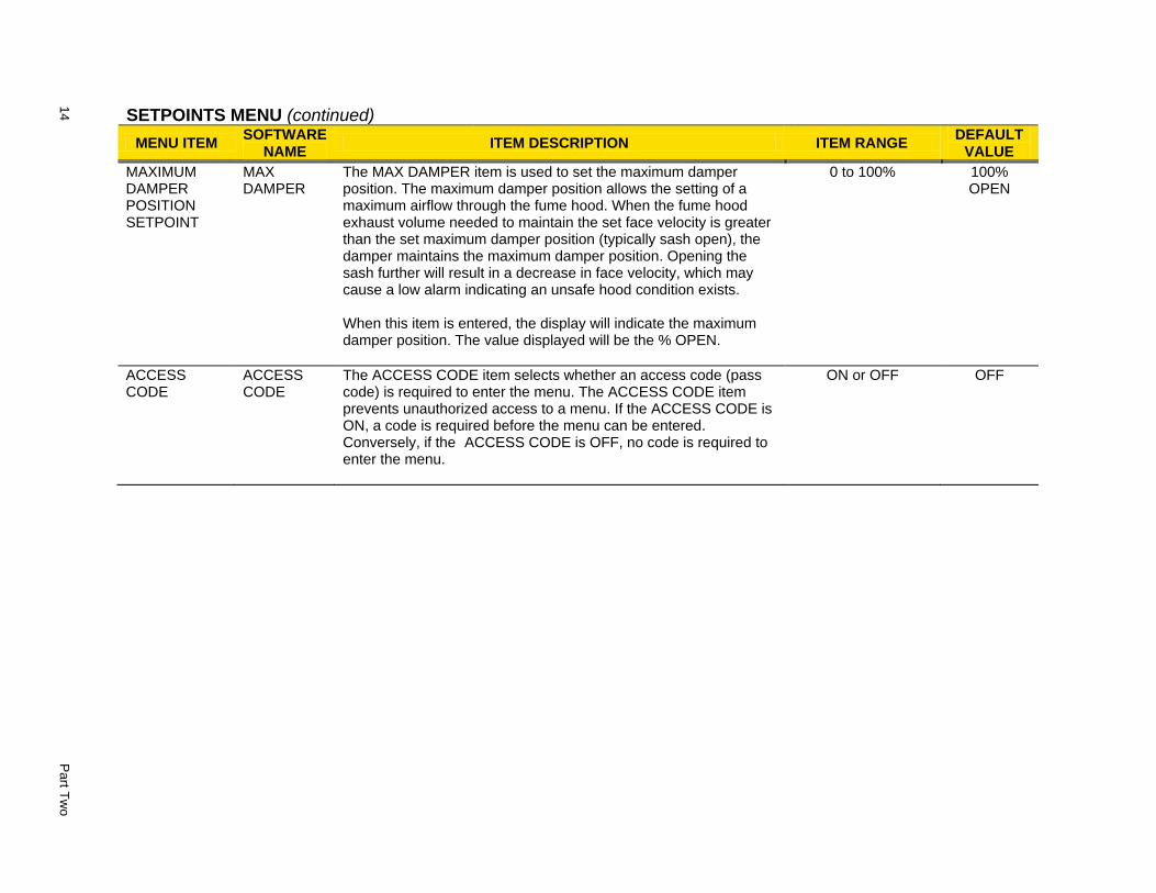
SETPOINTS MENU (continued)
MENU ITEMSOFTWARE
NAMEITEM DESCRIPTION ITEM RANGE
DEFAULT VALUE
MAXIMUM DAMPER POSITION SETPOINT
MAX DAMPER
The MAX DAMPER item is used to set the maximum damper position. The maximum damper position allows the setting of a maximum airflow through the fume hood. When the fume hood exhaust volume needed to maintain the set face velocity is greater than the set maximum damper position (typically sash open), the damper maintains the maximum damper position. Opening the sash further will result in a decrease in face velocity, which may cause a low alarm indicating an unsafe hood condition exists. When this item is entered, the display will indicate the maximum damper position. The value displayed will be the % OPEN.
0 to 100% 100% OPEN
ACCESS CODE
ACCESS CODE
The ACCESS CODE item selects whether an access code (pass code) is required to enter the menu. The ACCESS CODE item prevents unauthorized access to a menu. If the ACCESS CODE is ON, a code is required before the menu can be entered. Conversely, if the ACCESS CODE is OFF, no code is required to enter the menu.
ON or OFF OFF
Te
chn
ical S
ectio
n
15
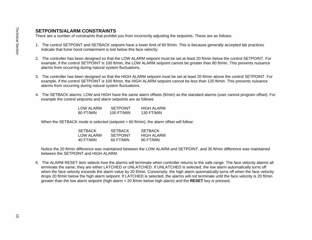
SETPOINTS/ALARM CONSTRAINTS There are a number of constraints that prohibit you from incorrectly adjusting the setpoints. These are as follows: 1. The control SETPOINT and SETBACK setpoint have a lower limit of 60 ft/min. This is because generally accepted lab practices
indicate that fume hood containment is lost below this face velocity. 2. The controller has been designed so that the LOW ALARM setpoint must be set at least 20 ft/min below the control SETPOINT. For
example, if the control SETPOINT is 100 ft/min, the LOW ALARM setpoint cannot be greater than 80 ft/min. This prevents nuisance alarms from occurring during natural system fluctuations.
3. The controller has been designed so that the HIGH ALARM setpoint must be set at least 20 ft/min above the control SETPOINT. For
example, if the control SETPOINT is 100 ft/min, the HIGH ALARM setpoint cannot be less than 120 ft/min. This prevents nuisance alarms from occurring during natural system fluctuations.
4. The SETBACK alarms; LOW and HIGH have the same alarm offsets (ft/min) as the standard alarms (user cannot program offset). For
example the control setpoints and alarm setpoints are as follows: LOW ALARM SETPOINT HIGH ALARM 80 FT/MIN 100 FT/MIN 130 FT/MIN
When the SETBACK mode is selected (setpoint = 60 ft/min), the alarm offset will follow: SETBACK SETBACK SETBACK LOW ALARM SETPOINT HIGH ALARM 40 FT/MIN 60 FT/MIN 90 FT/MIN
Notice the 20 ft/min difference was maintained between the LOW ALARM and SETPOINT, and 30 ft/min difference was maintained between the SETPOINT and HIGH ALARM.
5. The ALARM RESET item selects how the alarms will terminate when controller returns to the safe range. The face velocity alarms all
terminate the same; they are either LATCHED or UNLATCHED. If UNLATCHED is selected, the low alarm automatically turns off when the face velocity exceeds the alarm value by 20 ft/min. Conversely, the high alarm automatically turns off when the face velocity drops 20 ft/min below the high alarm setpoint. If LATCHED is selected, the alarms will not terminate until the face velocity is 20 ft/min
greater than the low alarm setpoint (high alarm = 20 ft/min below high alarm) and the RESET key is pressed.

16
Part T
wo
CONFIGURE MENU
MENU ITEMSOFTWARE
NAMEITEM DESCRIPTION ITEM RANGE
DEFAULT VALUE
DISPLAY AVERAGE
DISPLAY AVG
The DISPLAY AVG item selects the display’s averaging period. The display-averaging period is the length of time the face velocity has been averaged before being displayed. The DISPLAY AVG item value may be set between 0.3 and 40 seconds. The higher the averaging value, the more stable the display.
0.5, 1, 2, 3, 5, 10, 20 or 40 seconds
5 seconds
UNITS UNITS The UNITS item selects the unit of measure that the controller displays all velocity related menu items: setpoints, alarms, calibration, etc.
FT/MIN, m/s, FT/MIN
ALARM RESET
ALARM RESET
The ALARM RESET item selects how the alarms terminate after the unit returns to control setpoint. UNLATCHED (alarm follow) automatically resets the alarm when the face velocity is 20 ft/min greater than the low alarm setpoint, or 20 ft/min below the high alarm setpoint. LATCHED requires the staff to press
the RESET key after the face velocity exceeds the low alarm setpoint by 20 ft/min, or is 20 ft/min below the high alarm setpoint control setpoint. The ALARM RESET affects the audible alarm, visual alarm, and relay output, which means all are latched or unlatched.
LATCHED OR
UNLATCHED
UNLATCHED
OUTPUT
SIGNAL
OUTPUT SIG The OUTPUT SIG item selects the type of analog velocity signal output (not control output signal). The analog output signal can either be 0 to 10 VDC or 4 to 20 mA.
0 to 10 VDC or 4 to 20 mA
0 to 10 VDC
AUDIBLE DISABLE
AUD DISABLE
The AUD DISABLE item selects if the audible alarm can be permanently muted by pressing the mute key once when not in alarm, and twice if in alarm (yellow light turns on). ON means the alarm can be permanently muted from the keypad. OFF means the alarm can only be temporarily muted from the keypad.
ON or OFF ON
NETWORK PROTOCOL**
NET PROTOCOL
The NET PROTOCOL item selects the communications protocol used to interface with the building management system.
MODBUS or N2
MODBUS
Te
chn
ical S
ectio
n
17
CONFIGURE MENU (continued)
MENU ITEMSOFTWARE
NAMEITEM DESCRIPTION ITEM RANGE
DEFAULT VALUE
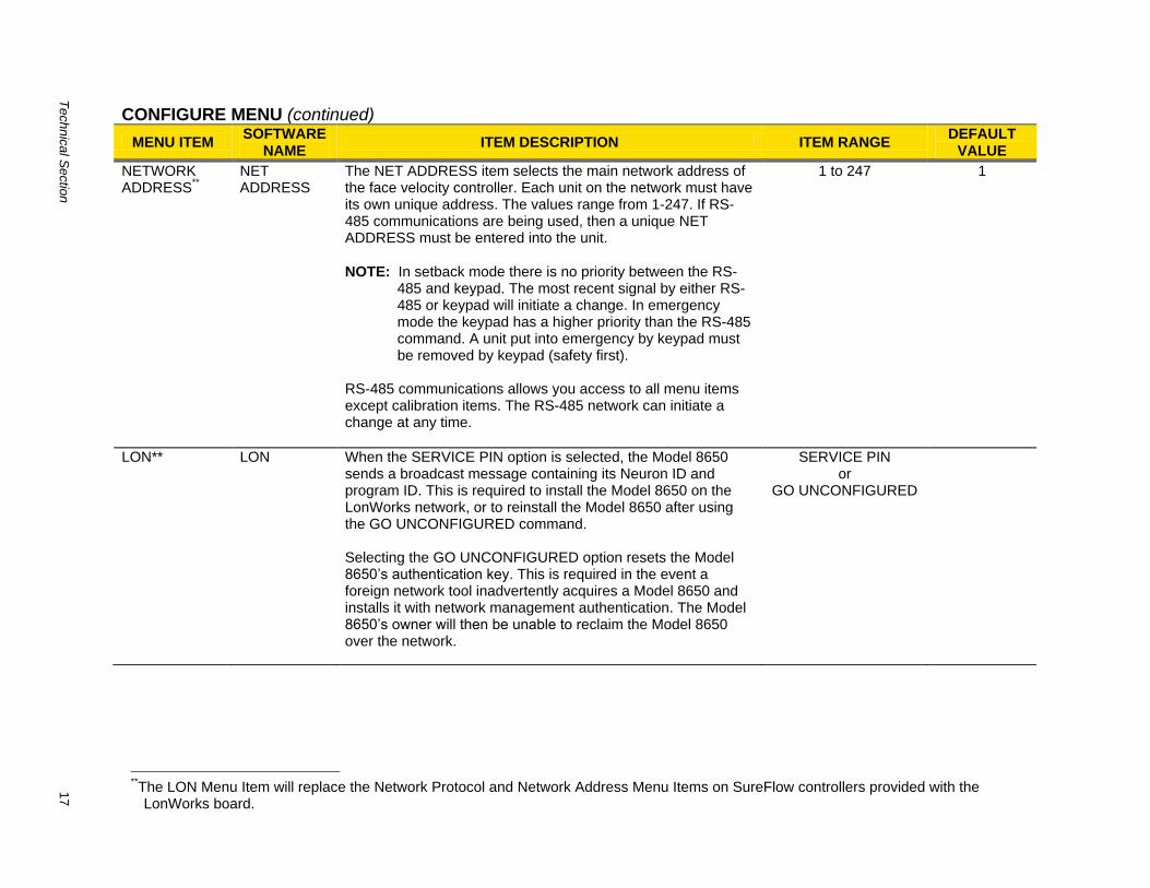
NETWORK ADDRESS
**
NET ADDRESS
The NET ADDRESS item selects the main network address of the face velocity controller. Each unit on the network must have its own unique address. The values range from 1-247. If RS-485 communications are being used, then a unique NET ADDRESS must be entered into the unit.
NOTE: In setback mode there is no priority between the RS-485 and keypad. The most recent signal by either RS-485 or keypad will initiate a change. In emergency mode the keypad has a higher priority than the RS-485 command. A unit put into emergency by keypad must be removed by keypad (safety first).
RS-485 communications allows you access to all menu items except calibration items. The RS-485 network can initiate a change at any time.
1 to 247 1
LON** LON When the SERVICE PIN option is selected, the Model 8650 sends a broadcast message containing its Neuron ID and program ID. This is required to install the Model 8650 on the LonWorks network, or to reinstall the Model 8650 after using the GO UNCONFIGURED command. Selecting the GO UNCONFIGURED option resets the Model 8650’s authentication key. This is required in the event a foreign network tool inadvertently acquires a Model 8650 and installs it with network management authentication. The Model 8650’s owner will then be unable to reclaim the Model 8650 over the network.
SERVICE PIN or
GO UNCONFIGURED
**The LON Menu Item will replace the Network Protocol and Network Address Menu Items on SureFlow controllers provided with the LonWorks board.
18
Part T
wo
CONFIGURE MENU (continued)
MENU ITEMSOFTWARE
NAMEITEM DESCRIPTION ITEM RANGE
DEFAULT VALUE
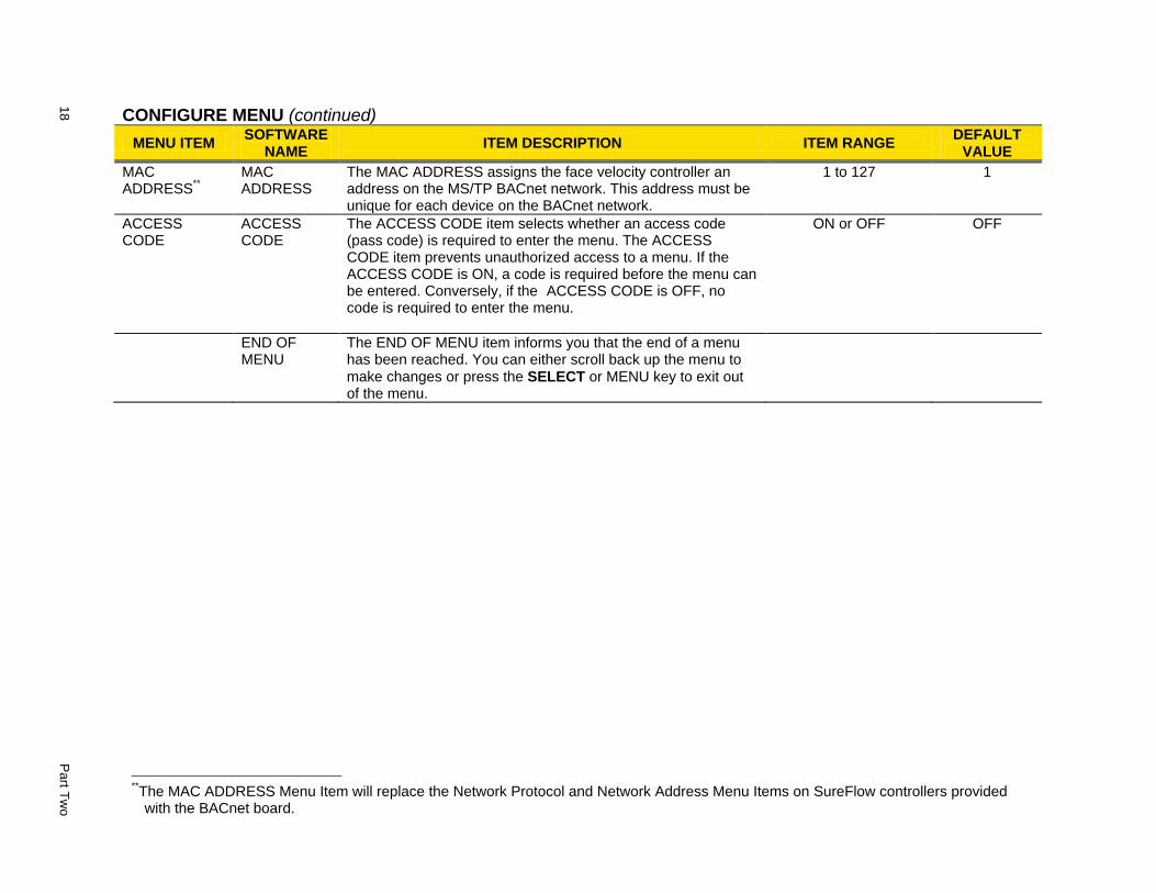
MAC ADDRESS
**
MAC ADDRESS
The MAC ADDRESS assigns the face velocity controller an address on the MS/TP BACnet network. This address must be unique for each device on the BACnet network.
1 to 127 1
ACCESS CODE
ACCESS CODE
The ACCESS CODE item selects whether an access code (pass code) is required to enter the menu. The ACCESS CODE item prevents unauthorized access to a menu. If the ACCESS CODE is ON, a code is required before the menu can be entered. Conversely, if the ACCESS CODE is OFF, no code is required to enter the menu.
ON or OFF OFF
END OF MENU
The END OF MENU item informs you that the end of a menu has been reached. You can either scroll back up the menu to
make changes or press the SELECT or MENU key to exit out of the menu.
**The MAC ADDRESS Menu Item will replace the Network Protocol and Network Address Menu Items on SureFlow controllers provided with the BACnet board.
Te
chn
ical S
ectio
n
19
CALIBRATION MENU
MENU ITEMSOFTWARE
NAMEITEM DESCRIPTION ITEM RANGE
DEFAULT VALUE
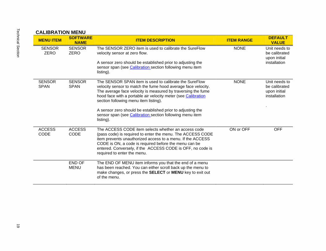
SENSOR ZERO
SENSOR ZERO
The SENSOR ZERO item is used to calibrate the SureFlow velocity sensor at zero flow. A sensor zero should be established prior to adjusting the sensor span (see Calibration section following menu item listing).
NONE Unit needs to be calibrated upon initial installation
SENSOR SPAN
SENSOR SPAN
The SENSOR SPAN item is used to calibrate the SureFlow velocity sensor to match the fume hood average face velocity. The average face velocity is measured by traversing the fume hood face with a portable air velocity meter (see Calibration section following menu item listing). A sensor zero should be established prior to adjusting the sensor span (see Calibration section following menu item listing).
NONE Unit needs to be calibrated upon initial installation .
ACCESS CODE
ACCESS CODE
The ACCESS CODE item selects whether an access code (pass code) is required to enter the menu. The ACCESS CODE item prevents unauthorized access to a menu. If the ACCESS CODE is ON, a code is required before the menu can be entered. Conversely, if the ACCESS CODE is OFF, no code is required to enter the menu.
ON or OFF OFF
END OF MENU
The END OF MENU item informs you that the end of a menu has been reached. You can either scroll back up the menu to
make changes, or press the SELECT or MENU key to exit out of the menu.
20
Part T
wo
CONTROL MENU
MENU ITEMSOFTWARE
NAMEITEM DESCRIPTION ITEM RANGE
DEFAULT VALUE
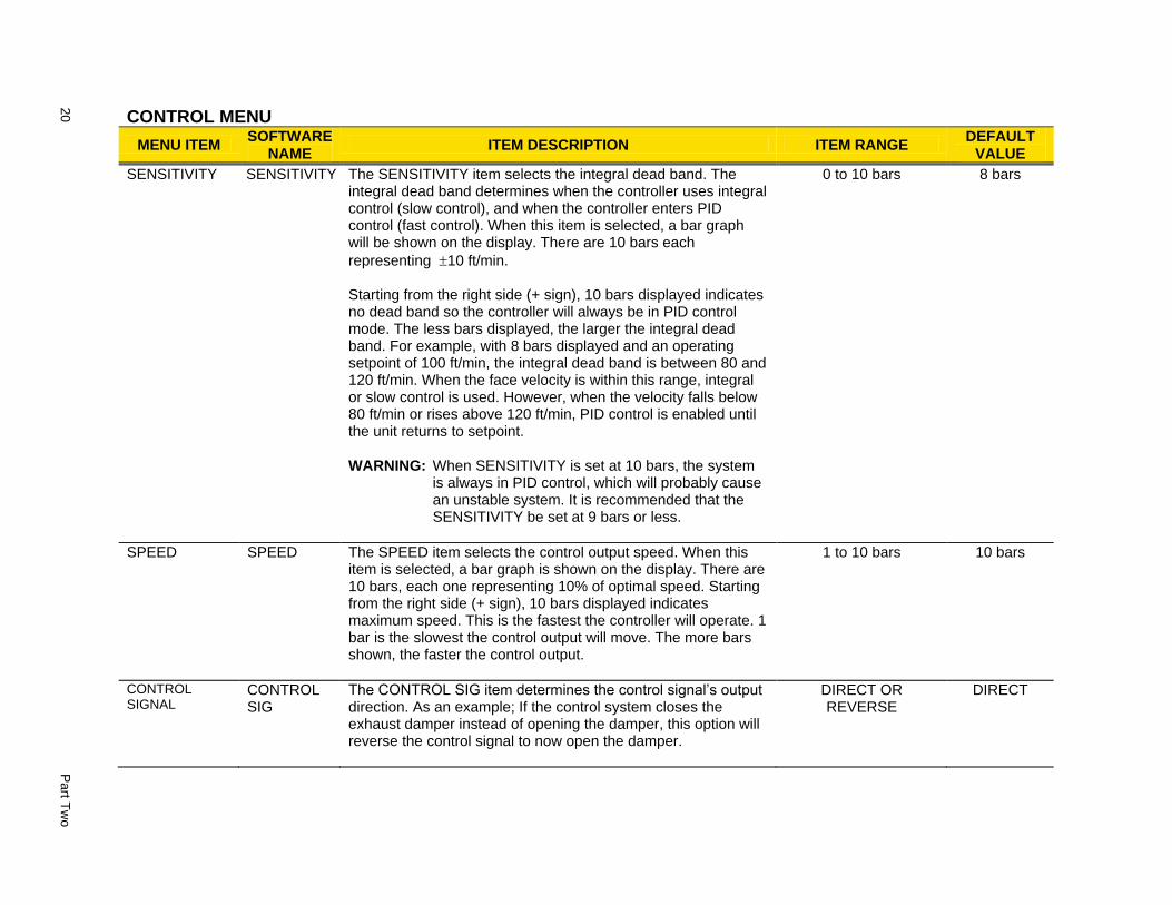
SENSITIVITY SENSITIVITY The SENSITIVITY item selects the integral dead band. The integral dead band determines when the controller uses integral control (slow control), and when the controller enters PID control (fast control). When this item is selected, a bar graph will be shown on the display. There are 10 bars each
representing 10 ft/min. Starting from the right side (+ sign), 10 bars displayed indicates no dead band so the controller will always be in PID control mode. The less bars displayed, the larger the integral dead band. For example, with 8 bars displayed and an operating setpoint of 100 ft/min, the integral dead band is between 80 and 120 ft/min. When the face velocity is within this range, integral or slow control is used. However, when the velocity falls below 80 ft/min or rises above 120 ft/min, PID control is enabled until the unit returns to setpoint.
WARNING: When SENSITIVITY is set at 10 bars, the system is always in PID control, which will probably cause an unstable system. It is recommended that the SENSITIVITY be set at 9 bars or less.
0 to 10 bars 8 bars
SPEED SPEED The SPEED item selects the control output speed. When this item is selected, a bar graph is shown on the display. There are 10 bars, each one representing 10% of optimal speed. Starting from the right side (+ sign), 10 bars displayed indicates maximum speed. This is the fastest the controller will operate. 1 bar is the slowest the control output will move. The more bars shown, the faster the control output.
1 to 10 bars 10 bars
CONTROL SIGNAL
CONTROL SIG
The CONTROL SIG item determines the control signal’s output direction. As an example; If the control system closes the exhaust damper instead of opening the damper, this option will reverse the control signal to now open the damper.
DIRECT OR REVERSE
DIRECT
Te
chn
ical S
ectio
n
21
CONTROL MENU (continued)
MENU ITEMSOFTWARE
NAMEITEM DESCRIPTION ITEM RANGE
DEFAULT VALUE
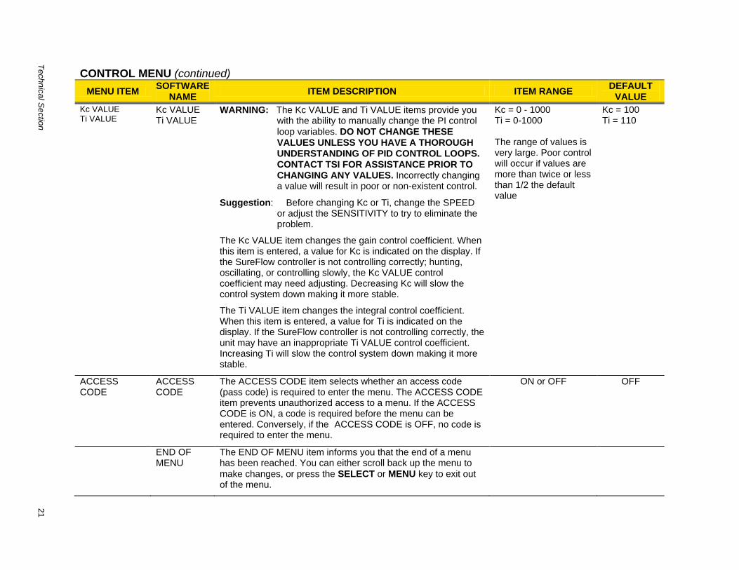
Kc VALUE Ti VALUE
Kc VALUE Ti VALUE
WARNING: The Kc VALUE and Ti VALUE items provide you with the ability to manually change the PI control
loop variables. DO NOT CHANGE THESE
VALUES UNLESS YOU HAVE A THOROUGH UNDERSTANDING OF PID CONTROL LOOPS. CONTACT TSI FOR ASSISTANCE PRIOR TO CHANGING ANY VALUES. Incorrectly changing a value will result in poor or non-existent control.
Suggestion: Before changing Kc or Ti, change the SPEED or adjust the SENSITIVITY to try to eliminate the problem.
The Kc VALUE item changes the gain control coefficient. When this item is entered, a value for Kc is indicated on the display. If the SureFlow controller is not controlling correctly; hunting, oscillating, or controlling slowly, the Kc VALUE control coefficient may need adjusting. Decreasing Kc will slow the control system down making it more stable.
The Ti VALUE item changes the integral control coefficient. When this item is entered, a value for Ti is indicated on the display. If the SureFlow controller is not controlling correctly, the unit may have an inappropriate Ti VALUE control coefficient. Increasing Ti will slow the control system down making it more stable.
Kc = 0 - 1000 Ti = 0-1000 The range of values is very large. Poor control will occur if values are more than twice or less than 1/2 the default value
Kc = 100 Ti = 110
ACCESS CODE
ACCESS CODE
The ACCESS CODE item selects whether an access code (pass code) is required to enter the menu. The ACCESS CODE item prevents unauthorized access to a menu. If the ACCESS CODE is ON, a code is required before the menu can be entered. Conversely, if the ACCESS CODE is OFF, no code is required to enter the menu.
ON or OFF OFF
END OF MENU
The END OF MENU item informs you that the end of a menu has been reached. You can either scroll back up the menu to
make changes, or press the SELECT or MENU key to exit out of the menu.
22 Part Two
Calibration The calibration section explains how to calibrate the SureFlow velocity controller and how to zero a TSI flow station pressure transducer (CFM option). The SureFlow Face Velocity Controller must be calibrated, after being installed on the fume hood, to provide accurate indication of fume hood face velocity. An orange WARNING label is attached to every SureFlow controller indicating this as follows:
WARNING
Unit is not calibrated! Remove label only after field
calibration is complete.
The label is to be removed when calibration is complete.
NOTE: This section assumes that the velocity sensor has been correctly installed. Inaccurate readings may be detected if velocity sensor is not installed correctly. Review the Installation Instructions and verify that the sensor is installed correctly (usually only a problem on initial set up).
The following items are needed to calibrate the SureFlow controller:
Masking tape
Portable Air Velocity Meter such as TSI VELOCICALC® Model 8384 or VELOCICHECK
®
Model 8330.
Calibrating Velocity Sensor
WARNING: The controller is disabled during sensor zero procedure and when adjusting the sensor span.
Enter CALIBRATION menu (see Software Programming if not familiar with keystroke procedure).
Sensor zero
1. Place a piece of tape over the velocity sensor opening to seal off air flowing past the sensor.
2. Select SENSOR ZERO item.
3. Press SELECT key. Sensor zero procedure, which takes 120 seconds, is automatic.
4. Press SELECT key to save the data.
5. Remove tape from velocity sensor.
Sensor span
NOTE: Always zero sensor prior to adjusting the sensor span. A comparison thermal anemometer is required to calibrate the velocity span. Confirm a good average face velocity is present in the fume face before adjusting the span.
1. Open the fume hood sash 60% and let the controller reach setpoint.
2. Select SENSOR SPAN item (30 second countdown).
3. Use a thermal anemometer to traverse the open sash area and obtain the average face velocity of the air passing into the hood.
4. Compare the thermal anemometer to the Model 8650 controller.
5. Press the / keys until the controller velocity matches the thermal anemometer velocity.
Technical Section 23
6. Press SELECT key to save sensor span.
7. Exit menu, calibration is complete.
WARNING: Calibrating the span on the SureFlow controller may be an iterative process that takes 1 to 3 trials to get an accurate calibration. Checking the calibration must be done after each trial until an accurate calibration is verified.
Flow Station Pressure Transducer Zero
NOTE: Flow stations are optional and may not be installed in your system.
1. Disconnect tubing between pressure transducer and flow station.
2. Enter calibration menu.
3. Select EXH FLO ZERO menu item.
4. Press SELECT key. Flow zero procedure, which takes 10 seconds, is automatic.
5. Press SELECT key to save data.
6. Connect tubing between pressure transducer and flow station.
Optimizing Controller Performance The SureFlow controller uses both integral and PID control methods. Integral control (slower control signal) is used when the controller is near setpoint. Integral control provides stability when natural system fluctuations occur such as operators working at hoods and lab doors opening. PID control (fast control) is used when responding to large disturbances to face velocity such as sash movements. PID control rapidly returns the face velocity to setpoint, thus assuring containment. Once the SureFlow controller is in PID control, it continues to control in this mode until the operating setpoint is met.
There are four menu items that change the characteristics of the control output signal; 1) SENSITIVITY 2) SPEED
3) Kc VALUE 4) Ti VALUE
TSI recommends only adjusting the SENSITIVITY and SPEED to fine tune the control signal. Only when the SPEED and SENSITIVITY items cannot provide a stable system should Kc VALUE and Ti VALUE be adjusted. The role of each menu item is covered in the Menu and Menu Items section of the manual. This section provides some guidance of when a menu item should be changed.
The controller is shipped with PID values that are appropriate for 95+ % of the fume hoods installed. In fume hoods where some adjustment is needed, minor changes to the SENSITIVITY and SPEED menu items will yield excellent control. The SENSITIVITY item selects when the unit goes into PID control. Each bar missing on the display indicates that the controller must be 10 ft/min away from control setpoint prior to activating PID control. If 4 bars are missing, the face velocity must be 40 ft/min off setpoint before PID control is activated. Conversely, if 2 bars are missing, the face velocity must only be 20 ft/min off setpoint before PID control is activated. The default of 2 bars missing is usually a good compromise between PID and integral control.
The SPEED menu item slows down the control output. The controller is shipped with a control signal capable of rotating the damper 90 degrees in 5 seconds. This may be too fast if the damper is in an unstable flow area (very near the exhaust fan), or there are competing air flows in
Part Two 24
the laboratory. SureFlow controllers modulating a VFD system will probably need to be slowed down, since the control signal is substantially faster than the VFD/fan can respond.
The remaining menu items, Kc VALUE and Ti VALUE should not be adjusted unless severe stability problems exist. Adjusting these variables may improve the response and stability, but the exact opposite may happen causing the controller to become unstable, hunt substantially, or have very slow response. If controller performance cannot be improved by adjusting the SPEED and SENSITIVITY, the two menu items can be manually set to their default values.
Maintenance and Repair Parts
The Model 8650 SureFlow Face Velocity Controller requires minimal maintenance. Periodic inspection of system components as well as an occasional velocity sensor cleaning are all that are needed to ensure that the Model 8650 is operating properly. The Model 8650 should be calibrated annually. Refer to the Calibration section for further information.
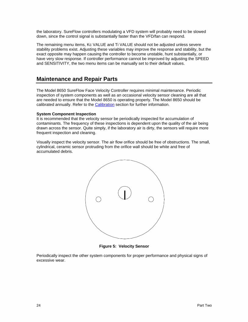
System Component Inspection It is recommended that the velocity sensor be periodically inspected for accumulation of contaminants. The frequency of these inspections is dependent upon the quality of the air being drawn across the sensor. Quite simply, if the laboratory air is dirty, the sensors will require more frequent inspection and cleaning. Visually inspect the velocity sensor. The air flow orifice should be free of obstructions. The small, cylindrical, ceramic sensor protruding from the orifice wall should be white and free of accumulated debris.
Figure 5: Velocity Sensor Periodically inspect the other system components for proper performance and physical signs of excessive wear.
Technical Section 25
Velocity Sensor Cleaning Accumulations of dust or dirt can be removed with a dry soft-bristled brush (such as an artist's brush). If necessary, water, alcohol, acetone, or trichlorethane may be used as a solvent to remove other contaminants. Use extreme care when cleaning the velocity sensors. The ceramic sensor may break if excessive pressure is applied, if sensor is scraped to remove contaminants, or if the cleaning apparatus abruptly impacts the sensor.
WARNING: If you are using a liquid to clean the sensor, turn off power to the Model 8650. Do
NOT apply power before velocity sensor completely dries.
Do NOT use compressed air to clean the velocity sensors.
Do NOT attempt to scrape contaminants from the velocity sensors. The velocity sensors are quite durable; however, scraping may cause mechanical damage and possibly break the sensor. Mechanical damage due to scraping voids the sensor warranty.
Replacement Parts All components of the Face Velocity Control system are field replaceable. Contact TSI or your nearest TSI Manufacturer's Representative for replacement part pricing and delivery.
Part Number Description
Found on back of unit
Model 8650 Face Velocity Controller
800320 Velocity sensor
800325 Velocity/Controller Sensor Cable
800414 Transformer Cable
800420 Transformer
800199 Controller Output Cable
800360 Electric Actuator
Troubleshooting Section The SureFlow Face Velocity Controller is designed to be trouble free. However, installation problems or interaction with other HVAC components may cause system problems. The SureFlow system is easy to troubleshoot if an organized approach to evaluate the system is taken. Troubleshooting is broken down into hardware (mechanical) and software problems. Hardware problems deal with the physical installation of the device. Hardware problems include wiring problems, incorrectly installed equipment, and add-ons or non-TSI equipment. Software problems include control problems, configuration problems, or interaction problems with the HVAC system. The hardware test described in this section determines that all TSI mechanical components are functioning correctly. The hardware test requires the diagnostics menu items to be accessed. If you are unfamiliar with the SureFlow controller menus, see Software Programming for keystroke procedure. Troubleshooting the majority of problems is usually quick if the hardware test is followed.
Part Two 26
Software and hardware problems are covered in the troubleshooting chart. Pick the problem that most closely resembles your problem and review the possible symptoms and corrective action. Software or system performance problems can and are affected by the supply air system, exhaust air system, or physical configuration of the room. Separating TSI system problems from the laboratory HVAC system can sometimes be difficult. TSI recommends confirming all hardware is operating correctly before troubleshooting software problems.
Hardware Test Three tests need to be performed in order to determine all hardware is functioning correctly. The tests are broken down into:
Confirming wiring is correct.
Confirming physical installation is correct.
Verifying mechanical components.
Confirming wiring is correct
The most common problem with installed hardware equipment is incorrect wiring. This problem usually exists on initial installation, or when modifications to the system take place. The wiring should be very closely checked to verify it exactly matches the wiring diagram. A wiring diagram is located in Appendix B of this manual. The TSI cables are all color coded to ensure proper wiring. Wiring associated with non-TSI components should be closely checked for correct installation. If non-TSI components are installed, consider disconnecting them for testing purposes.
Confirming physical installation is correct
All of the hardware components need to be installed properly. Review the installation instructions and verify components are installed properly at the correct location. This is easily done when the wiring is checked.
Verifying mechanical components
Verifying all TSI components are operating correctly requires following a simple procedure. The fastest procedure to confirm all equipment is operating is to first test the Digital Interface Module (DIM), and then go into the diagnostic menu to test each component.
NOTE: These tests require power to the units, so if unit has no power, refer to hardware
troubleshooting chart to eliminate power problem.
TEST - DIM
Press TEST key to verify DIM electronics are functioning correctly. At the end of the self test, the display will show SELF TEST - PASSED if all DIM electronics are good. If unit displays DATA ERROR at the end of the test, the software may be corrupted. Check all menu items to determine cause of DATA ERROR. If SELF TEST - PASSED is displayed, proceed to test individual components. Enter Diagnostics Menu and check the following:
Control output
Sensor input
Analog output
NOTE: These diagnostic menu items are explained in the Diagnostics Menu, which is at the end of this section of the manual, so their function is not reviewed here. If the SureFlow system passes each of the tests, the mechanical piece parts are all functioning correctly.
Technical Section 27
TEST - Control output/damper rotation
Enter CONTROL OUT menu item in diagnostics menu. A number between 0% OPEN and 100% OPEN will be displayed. Press the / keys until either 0% OPEN or 100% OPEN shows on the display. Note the position of the control damper. If display reads 0% OPEN, press the key until 100% OPEN is shown on display. If display reads 100% OPEN, press key until 0% OPEN is shown on display. Note the position of the damper. The damper should have rotated 90 degrees. If the damper rotated less than 85
degrees, see Troubleshooting chart; Control system is not controlling.
Return controller to normal operation, and allow unit to modulate damper. Press the
EMERGENCY key and verify damper opened completely. If damper opens completely, it passes test. If damper closes, go into CONTROL menu CONTROL SIG and change damper direction.
TEST - Sensor input
Enter SENSOR INPUT menu item in diagnostics menu. A number will be displayed. It is not important what the exact number is to pass this test. Tape over the velocity sensor. SENSOR INPUT should read a steady number. Remove tape and blow on sensor. Displayed value should change. If value changes, the unit passes. If display doesn’t change, go to Troubleshooting Chart; “SENSOR ERROR” flashing on display.
TEST - Analog output
NOTE: This test is only performed if analog output feature is being used. Enter ANALOG OUT menu item in diagnostics menu. A value between 0 and 255 will be displayed. Hook up a DC voltmeter to pins 9 and 10. Press the / keys to change output from 0 to 255. The value 255 corresponds to 0 volts (0 mA*) and 0 corresponds to 10 volts (20 mA). The value 150 corresponds to approximately 5 volts (12 mA). *The Analog Out menu item spans 0 to 20 mA in this function only. At all other times the analog output is 4 to 20 mA.
If unit passed all tests, the mechanical components are physically working. If problems still exist, go to troubleshooting chart for additional information, on both hardware and software symptoms.
Diagnostics Menu The items in the diagnostic menu aid in identifying problems the staff may encounter. The items in this menu temporarily change the function by pressing the / keys. No permanent change
occurs with these menu items (except ACCESS CODE). Items are exited by pressing the MENU key. When an item is exited, the SureFlow controller returns to its normal state.
NOTE: An access code is used to prohibit unauthorized access to the DIAGNOSTICS menu. If you attempt to enter the DIAGNOSTICS menu when the access code is enabled, "Enter Code" flashes on and off on the display. To enter the menu, enter the DIAGNOSTICS menu access code found in Appendix C.
Part Two 28
Control Output
Menu item - CONTROL OUT
The CONTROL OUT item changes the control output signal to the actuator/damper (or motor speed drive). When this item is entered, a number will be shown on the display indicating the last control output value. The range of values displayed is 0% OPEN – 100% OPEN. Pressing the / keys change the count on the display. Pressing the key should increase the displayed value, while pressing the key will decrease the displayed value. The control device should change as the number changes. On units controlling variable frequency drives, fan speed should increase or decrease as numbers change.
WARNING: The CONTROL OUT function overrides the face velocity control
signal. Adequate face velocity will NOT be maintained while in this menu item.
Analog Output
Menu Item - ANALOG OUT
The ANALOG OUT item varies the analog output from the SureFlow unit. When this item is entered, a number will be shown on the display indicating the last analog output value. The value displayed ranges from 0 to 255. The value 255 corresponds to 0 volts (4 mA) output and 0 corresponds to 10 Volts (20 mA) output. Pressing the key will increase the value displayed, and decrease the analog output. Pressing the key will decrease the value displayed and increase the analog output. The ANALOG OUT function can be used in conjunction with a volt meter to verify the analog output is correct.
Low Alarm Relay
Menu Item - LOW ALM REL
The LOW ALM REL item changes the state of the low alarm relay. When this item is entered, the display will indicate either OPEN or CLOSED. The / keys are used to toggle the state of the relay. The key is used to OPEN the alarm contact. The used to CLOSE the alarm contact. When the contact is closed, the LOW ALM REL should be in an alarm condition.
High Alarm Relay
Menu Item - HIGH ALM REL
The HIGH ALM REL item changes the state of the high alarm relay. When this item is entered, the display will indicate either OPEN or CLOSED. The / keys are used to toggle the state of the relay. The key is used to OPEN the alarm contact. The key is used to CLOSE the alarm contact. When the contact is closed, the HIGH ALM REL should be in an alarm condition.
Technical Section 29
Setback Input
Menu Item - SETBACK IN
The SETBACK IN item reads the current state of the setback contact input. When this item is entered, the display will indicate either OPEN or CLOSED. If the display indicates CLOSED, the SureFlow controller has been put into setback mode through the contact input. If the display indicates OPEN, the SureFlow controller has not been put into setback mode through the contact input.
NOTE: The SureFlow controller may be in setback mode if it has been initiated through the keypad or the RS-485 network.
Emergency Input
Menu item - EMERGENCY IN
The EMERGENCY IN item reads the current state of the emergency contact input. When this item is entered, the display will indicate either OPEN or CLOSED. If the display indicates CLOSED, the SureFlow controller has been put into emergency mode through the contact input. If the display indicates OPEN, the SureFlow controller has not been put into emergency mode through the contact input. However, the SureFlow controller may be in emergency mode if it has been initiated through the keypad or the RS-485 network.
Sensor Input
Menu item - SENSOR INPUT
The SENSOR INPUT item verifies that the DIM or controller electronics is receiving a signal from the sensor. When this item is entered, a number will be indicated on the display. The exact number displayed is relatively unimportant. It is more important that the displayed number changes when the velocity changes (blow on sensor, move sash, etc.). If display does not change, see Troubleshooting chart; “SENSOR ERROR” flashing on display.
Access Code
Menu Item - ACCESS CODE
The ACCESS CODE item selects whether an access code (pass code) is required to enter the menu. The ACCESS CODE item prevents unauthorized access to a menu. If the ACCESS CODE is ON, a code is required before the menu can be entered. Conversely, if the ACCESS CODE is OFF, no code is required to enter the menu.
Part Two 30
Troubleshooting Chart
Symptom Possible Cause Corrective Action
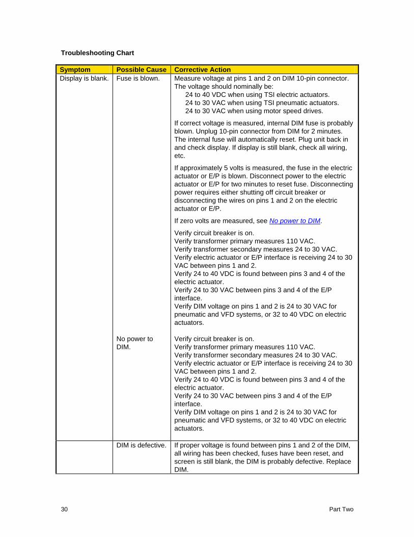
Display is blank. Fuse is blown. Measure voltage at pins 1 and 2 on DIM 10-pin connector.
The voltage should nominally be:
24 to 40 VDC when using TSI electric actuators.
24 to 30 VAC when using TSI pneumatic actuators.
24 to 30 VAC when using motor speed drives.
If correct voltage is measured, internal DIM fuse is probably
blown. Unplug 10-pin connector from DIM for 2 minutes.
The internal fuse will automatically reset. Plug unit back in
and check display. If display is still blank, check all wiring,
etc.
If approximately 5 volts is measured, the fuse in the electric
actuator or E/P is blown. Disconnect power to the electric
actuator or E/P for two minutes to reset fuse. Disconnecting
power requires either shutting off circuit breaker or
disconnecting the wires on pins 1 and 2 on the electric
actuator or E/P.
If zero volts are measured, see No power to DIM.
Verify circuit breaker is on.
Verify transformer primary measures 110 VAC.
Verify transformer secondary measures 24 to 30 VAC.
Verify electric actuator or E/P interface is receiving 24 to 30
VAC between pins 1 and 2.
Verify 24 to 40 VDC is found between pins 3 and 4 of the
electric actuator.
Verify 24 to 30 VAC between pins 3 and 4 of the E/P
interface.
Verify DIM voltage on pins 1 and 2 is 24 to 30 VAC for
pneumatic and VFD systems, or 32 to 40 VDC on electric
actuators.
No power to
DIM.
Verify circuit breaker is on.
Verify transformer primary measures 110 VAC.
Verify transformer secondary measures 24 to 30 VAC.
Verify electric actuator or E/P interface is receiving 24 to 30
VAC between pins 1 and 2.
Verify 24 to 40 VDC is found between pins 3 and 4 of the
electric actuator.
Verify 24 to 30 VAC between pins 3 and 4 of the E/P
interface.
Verify DIM voltage on pins 1 and 2 is 24 to 30 VAC for
pneumatic and VFD systems, or 32 to 40 VDC on electric
actuators.
DIM is defective. If proper voltage is found between pins 1 and 2 of the DIM,
all wiring has been checked, fuses have been reset, and
screen is still blank, the DIM is probably defective. Replace
DIM.
Technical Section 31
Symptom Possible Cause Corrective Action
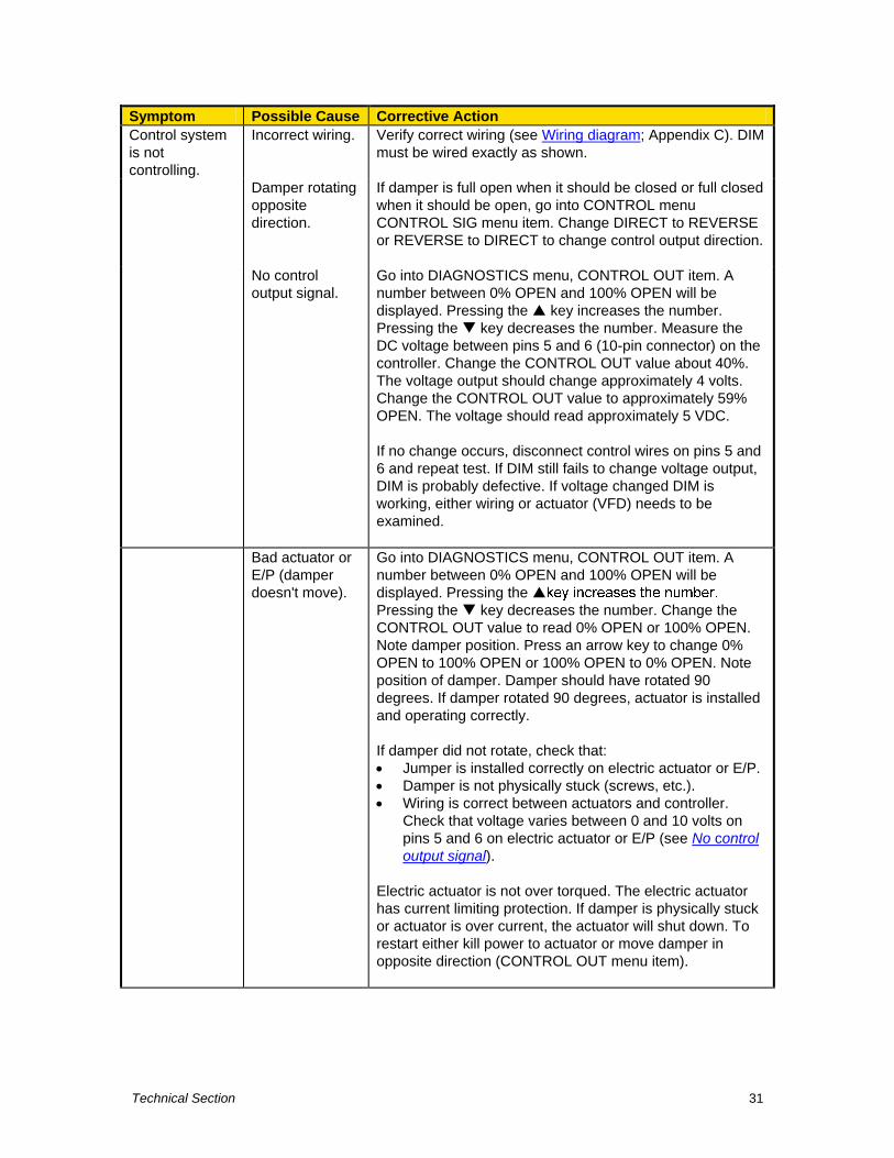
Control system
is not
controlling.
Incorrect wiring.
Verify correct wiring (see Wiring diagram; Appendix C). DIM
must be wired exactly as shown.
Damper rotating
opposite
direction.
If damper is full open when it should be closed or full closed
when it should be open, go into CONTROL menu
CONTROL SIG menu item. Change DIRECT to REVERSE
or REVERSE to DIRECT to change control output direction.
No control
output signal.
Go into DIAGNOSTICS menu, CONTROL OUT item. A
number between 0% OPEN and 100% OPEN will be
displayed. Pressing the key increases the number.
Pressing the key decreases the number. Measure the
DC voltage between pins 5 and 6 (10-pin connector) on the
controller. Change the CONTROL OUT value about 40%.
The voltage output should change approximately 4 volts.
Change the CONTROL OUT value to approximately 59%
OPEN. The voltage should read approximately 5 VDC.
If no change occurs, disconnect control wires on pins 5 and
6 and repeat test. If DIM still fails to change voltage output,
DIM is probably defective. If voltage changed DIM is
working, either wiring or actuator (VFD) needs to be
examined.
Bad actuator or
E/P (damper
doesn't move).
Go into DIAGNOSTICS menu, CONTROL OUT item. A
number between 0% OPEN and 100% OPEN will be
displayed. Pressing the
Pressing the key decreases the number. Change the
CONTROL OUT value to read 0% OPEN or 100% OPEN.
Note damper position. Press an arrow key to change 0%
OPEN to 100% OPEN or 100% OPEN to 0% OPEN. Note
position of damper. Damper should have rotated 90
degrees. If damper rotated 90 degrees, actuator is installed
and operating correctly.
If damper did not rotate, check that:
Jumper is installed correctly on electric actuator or E/P.
Damper is not physically stuck (screws, etc.).
Wiring is correct between actuators and controller.
Check that voltage varies between 0 and 10 volts on
pins 5 and 6 on electric actuator or E/P (see No control
output signal).
Electric actuator is not over torqued. The electric actuator
has current limiting protection. If damper is physically stuck
or actuator is over current, the actuator will shut down. To
restart either kill power to actuator or move damper in
opposite direction (CONTROL OUT menu item).
Part Two 32
Symptom Possible Cause Corrective Action
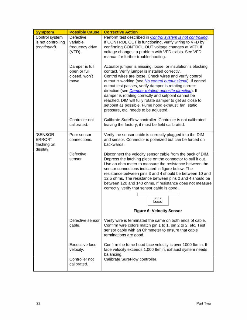
Control system
is not controlling
(continued).
Defective
variable
frequency drive
(VFD).
Perform test described in Control system is not controlling.
If CONTROL OUT is functioning, verify wiring to VFD by
confirming CONTROL OUT voltage changes at VFD. If
voltage changes, a problem with VFD exists. See VFD
manual for further troubleshooting.
Damper is full
open or full
closed, won’t
move.
Actuator jumper is missing, loose, or insulation is blocking
contact. Verify jumper is installed correctly.
Control wires are loose. Check wires and verify control
output is working (see No control output signal). If control
output test passes, verify damper is rotating correct
direction (see Damper rotating opposite direction). If
damper is rotating correctly and setpoint cannot be
reached, DIM will fully rotate damper to get as close to
setpoint as possible. Fume hood exhaust; fan, static
pressure, etc. needs to be adjusted.
.
Controller not
calibrated.
Calibrate SureFlow controller. Controller is not calibrated
leaving the factory, it must be field calibrated.
―SENSOR
ERROR‖
flashing on
display.
Poor sensor
connections.
Verify the sensor cable is correctly plugged into the DIM
and sensor. Connector is polarized but can be forced on
backwards.
Defective
sensor.
Disconnect the velocity sensor cable from the back of DIM.
Depress the latching piece on the connector to pull it out.
Use an ohm meter to measure the resistance between the
sensor connections indicated in figure below. The
resistance between pins 3 and 4 should be between 10 and
12.5 ohms. The resistance between pins 2 and 4 should be
between 120 and 140 ohms. If resistance does not measure
correctly, verify that sensor cable is good.
Figure 6: Velocity Sensor
Defective sensor
cable.
Verify wire is terminated the same on both ends of cable.
Confirm wire colors match pin 1 to 1, pin 2 to 2, etc. Test
sensor cable with an Ohmmeter to ensure that cable
terminations are good.
Excessive face
velocity.
Confirm the fume hood face velocity is over 1000 ft/min. If
face velocity exceeds 1,000 ft/min, exhaust system needs
balancing.
Controller not
calibrated.
Calibrate SureFlow controller.
Technical Section 33
Symptom Possible Cause Corrective Action
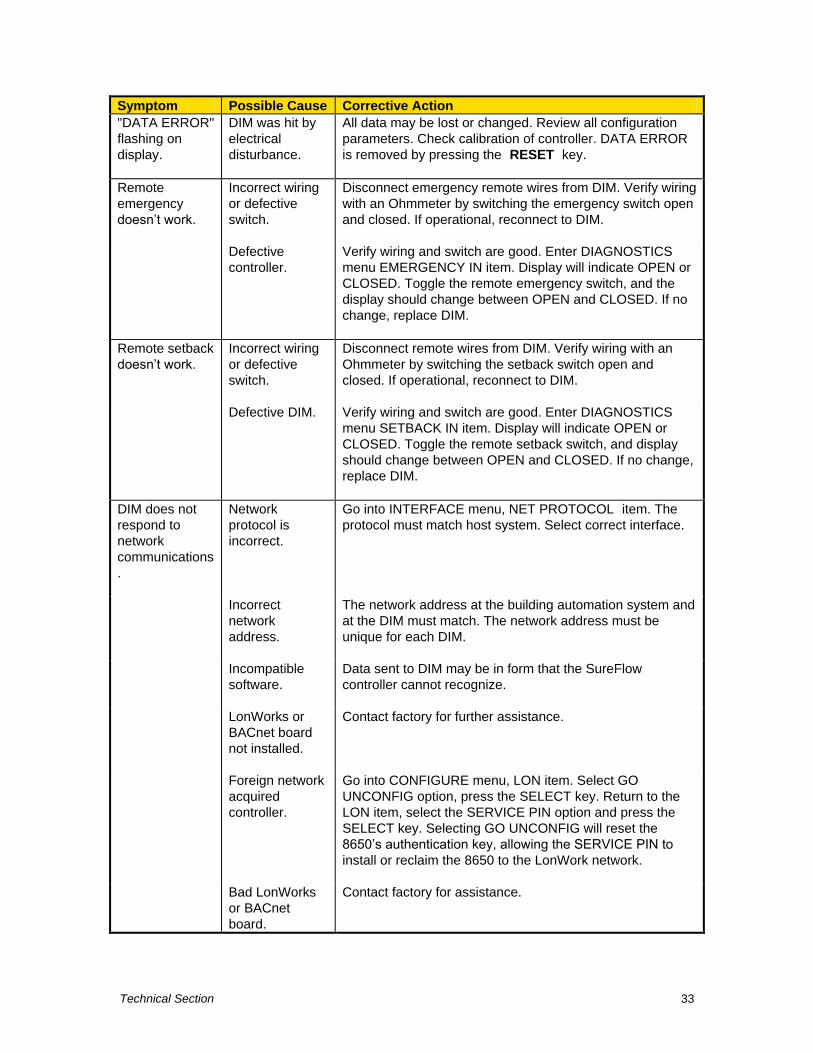
"DATA ERROR"
flashing on
display.
DIM was hit by
electrical
disturbance.
All data may be lost or changed. Review all configuration
parameters. Check calibration of controller. DATA ERROR
is removed by pressing the RESET key.
Remote
emergency
doesn’t work.
Incorrect wiring
or defective
switch.
Disconnect emergency remote wires from DIM. Verify wiring
with an Ohmmeter by switching the emergency switch open
and closed. If operational, reconnect to DIM.
Defective
controller.
Verify wiring and switch are good. Enter DIAGNOSTICS
menu EMERGENCY IN item. Display will indicate OPEN or
CLOSED. Toggle the remote emergency switch, and the
display should change between OPEN and CLOSED. If no
change, replace DIM.
Remote setback
doesn’t work.
Incorrect wiring
or defective
switch.
Disconnect remote wires from DIM. Verify wiring with an
Ohmmeter by switching the setback switch open and
closed. If operational, reconnect to DIM.
Defective DIM. Verify wiring and switch are good. Enter DIAGNOSTICS
menu SETBACK IN item. Display will indicate OPEN or
CLOSED. Toggle the remote setback switch, and display
should change between OPEN and CLOSED. If no change,
replace DIM.
DIM does not
respond to
network
communications
.
Network
protocol is
incorrect.
Go into INTERFACE menu, NET PROTOCOL item. The
protocol must match host system. Select correct interface.
Incorrect
network
address.
The network address at the building automation system and
at the DIM must match. The network address must be
unique for each DIM.
Incompatible
software.
Data sent to DIM may be in form that the SureFlow
controller cannot recognize.
LonWorks or
BACnet board
not installed.
Contact factory for further assistance.
Foreign network
acquired
controller.
Go into CONFIGURE menu, LON item. Select GO
UNCONFIG option, press the SELECT key. Return to the
LON item, select the SERVICE PIN option and press the
SELECT key. Selecting GO UNCONFIG will reset the
8650’s authentication key, allowing the SERVICE PIN to
install or reclaim the 8650 to the LonWork network.
Bad LonWorks
or BACnet
board.
Contact factory for assistance.
Part Two 34
Symptom Possible Cause Corrective Action
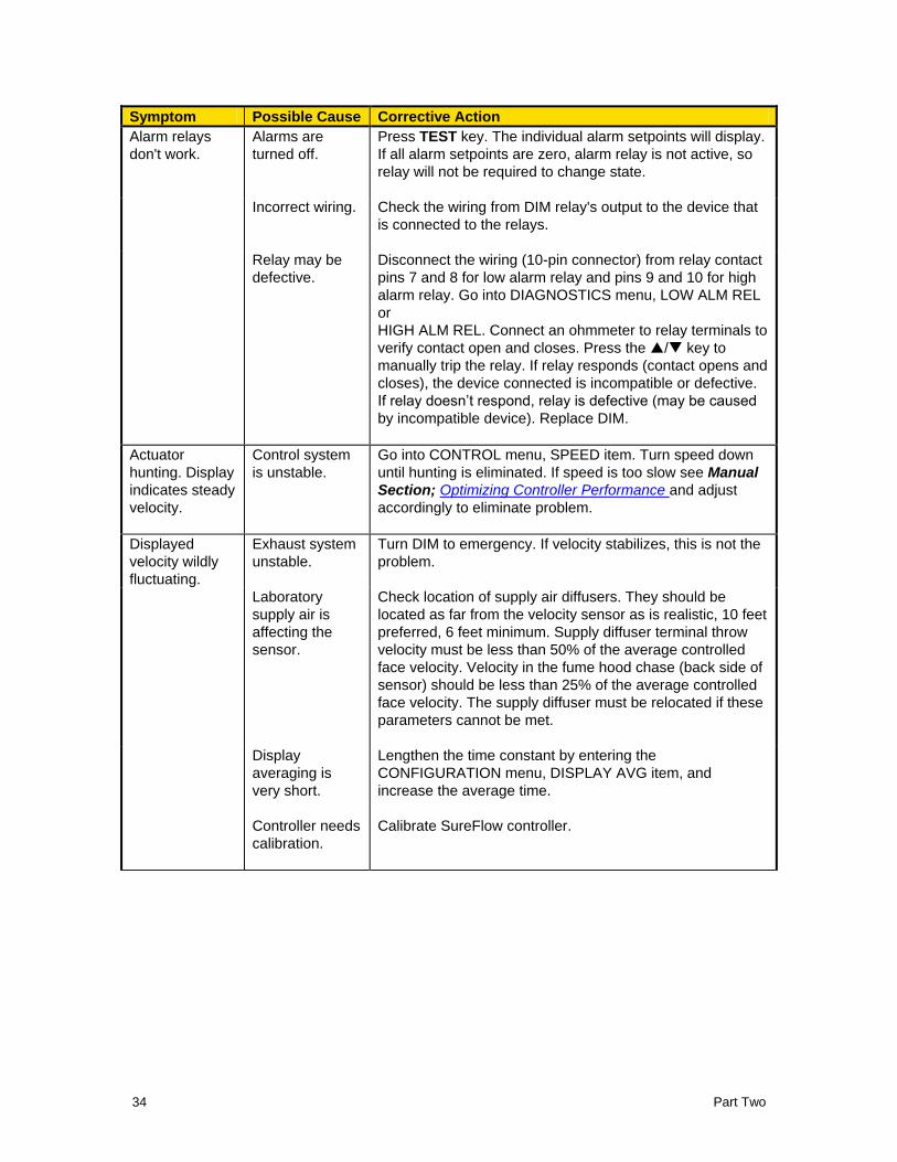
Alarm relays
don't work.
Alarms are
turned off.
Press TEST key. The individual alarm setpoints will display.
If all alarm setpoints are zero, alarm relay is not active, so
relay will not be required to change state.
Incorrect wiring. Check the wiring from DIM relay's output to the device that
is connected to the relays.
Relay may be
defective.
Disconnect the wiring (10-pin connector) from relay contact
pins 7 and 8 for low alarm relay and pins 9 and 10 for high
alarm relay. Go into DIAGNOSTICS menu, LOW ALM REL
or
HIGH ALM REL. Connect an ohmmeter to relay terminals to
verify contact open and closes. Press the / key to
manually trip the relay. If relay responds (contact opens and
closes), the device connected is incompatible or defective.
If relay doesn’t respond, relay is defective (may be caused
by incompatible device). Replace DIM.
Actuator
hunting. Display
indicates steady
velocity.
Control system
is unstable.
Go into CONTROL menu, SPEED item. Turn speed down
until hunting is eliminated. If speed is too slow see Manual
Section; Optimizing Controller Performance and adjust
accordingly to eliminate problem.
Displayed
velocity wildly
fluctuating.
Exhaust system
unstable.
Turn DIM to emergency. If velocity stabilizes, this is not the
problem.
Laboratory
supply air is
affecting the
sensor.
Check location of supply air diffusers. They should be
located as far from the velocity sensor as is realistic, 10 feet
preferred, 6 feet minimum. Supply diffuser terminal throw
velocity must be less than 50% of the average controlled
face velocity. Velocity in the fume hood chase (back side of
sensor) should be less than 25% of the average controlled
face velocity. The supply diffuser must be relocated if these
parameters cannot be met.
Display
averaging is
very short.
Lengthen the time constant by entering the
CONFIGURATION menu, DISPLAY AVG item, and
increase the average time.
Controller needs
calibration.
Calibrate SureFlow controller.
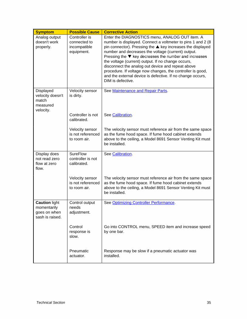
Technical Section 35
Symptom Possible Cause Corrective Action
Analog output
doesn't work
properly.
Controller is
connected to
incompatible
equipment.
Enter the DIAGNOSTICS menu, ANALOG OUT item. A
number is displayed. Connect a voltmeter to pins 1 and 2 (8
pin connector). Pressing the key increases the displayed
number and decreases the voltage (current) output.
Pressing the
the voltage (current) output. If no change occurs,
disconnect the analog out device and repeat above
procedure. If voltage now changes, the controller is good,
and the external device is defective. If no change occurs,
DIM is defective.
Displayed
velocity doesn't
match
measured
velocity.
Velocity sensor
is dirty.
See Maintenance and Repair Parts.
Controller is not
calibrated.
See Calibration.
Velocity sensor
is not referenced
to room air.
The velocity sensor must reference air from the same space
as the fume hood space. If fume hood cabinet extends
above to the ceiling, a Model 8691 Sensor Venting Kit must
be installed.
Display does
not read zero
flow at zero
flow.
SureFlow
controller is not
calibrated.
See Calibration.
Velocity sensor
is not referenced
to room air.
The velocity sensor must reference air from the same space
as the fume hood space. If fume hood cabinet extends
above to the ceiling, a Model 8691 Sensor Venting Kit must
be installed.
Caution light
momentarily
goes on when
sash is raised.
Control output
needs
adjustment.
See Optimizing Controller Performance.
Control
response is
slow.
Go into CONTROL menu, SPEED item and increase speed
by one bar.
Pneumatic
actuator.
Response may be slow if a pneumatic actuator was
installed.
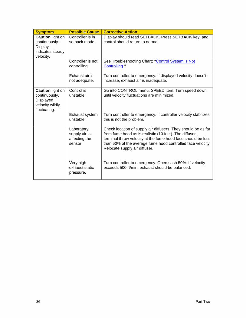
Part Two 36
Symptom Possible Cause Corrective Action
Caution light on
continuously.
Display
indicates steady
velocity.
Controller is in
setback mode.
Display should read SETBACK. Press SETBACK key, and
control should return to normal.
Controller is not
controlling.
See Troubleshooting Chart; "Control System is Not
Controlling."
Exhaust air is
not adequate.
Turn controller to emergency. If displayed velocity doesn't
increase, exhaust air is inadequate.
Caution light on
continuously.
Displayed
velocity wildly
fluctuating.
Control is
unstable.
Go into CONTROL menu, SPEED item. Turn speed down
until velocity fluctuations are minimized.
Exhaust system
unstable.
Turn controller to emergency. If controller velocity stabilizes,
this is not the problem.
Laboratory
supply air is
affecting the
sensor.
Check location of supply air diffusers. They should be as far
from fume hood as is realistic (10 feet). The diffuser
terminal throw velocity at the fume hood face should be less
than 50% of the average fume hood controlled face velocity.
Relocate supply air diffuser.
Very high
exhaust static
pressure.
Turn controller to emergency. Open sash 50%. If velocity
exceeds 500 ft/min, exhaust should be balanced.
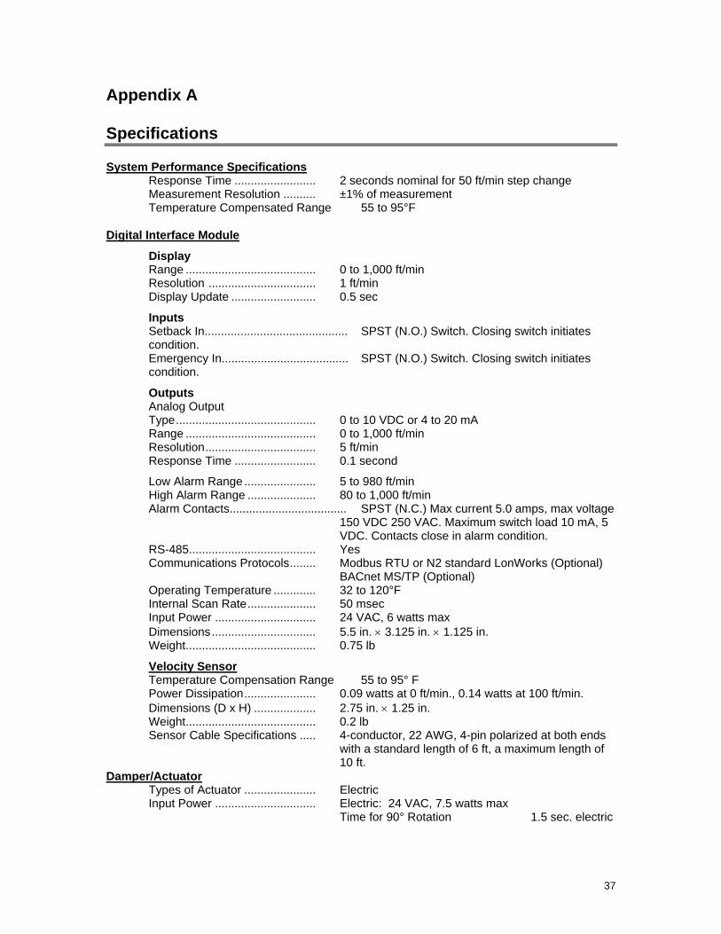
37
Appendix A
Specifications
System Performance Specifications Response Time ......................... 2 seconds nominal for 50 ft/min step change Measurement Resolution .......... ±1% of measurement Temperature Compensated Range 55 to 95°F
Digital Interface Module
Display Range ........................................ 0 to 1,000 ft/min Resolution ................................. 1 ft/min Display Update .......................... 0.5 sec
Inputs Setback In............................................ SPST (N.O.) Switch. Closing switch initiates condition. Emergency In....................................... SPST (N.O.) Switch. Closing switch initiates condition.
Outputs Analog Output Type ........................................... 0 to 10 VDC or 4 to 20 mA Range ........................................ 0 to 1,000 ft/min Resolution .................................. 5 ft/min Response Time ......................... 0.1 second
Low Alarm Range ...................... 5 to 980 ft/min High Alarm Range ..................... 80 to 1,000 ft/min Alarm Contacts.................................... SPST (N.C.) Max current 5.0 amps, max voltage
150 VDC 250 VAC. Maximum switch load 10 mA, 5 VDC. Contacts close in alarm condition.
RS-485 ....................................... Yes Communications Protocols ........ Modbus RTU or N2 standard LonWorks (Optional)
BACnet MS/TP (Optional) Operating Temperature ............. 32 to 120°F Internal Scan Rate ..................... 50 msec Input Power ............................... 24 VAC, 6 watts max
Dimensions ................................ 5.5 in. 3.125 in. 1.125 in. Weight ........................................ 0.75 lb
Velocity Sensor Temperature Compensation Range 55 to 95° F Power Dissipation ...................... 0.09 watts at 0 ft/min., 0.14 watts at 100 ft/min.
Dimensions (D x H) ................... 2.75 in. 1.25 in. Weight ........................................ 0.2 lb Sensor Cable Specifications ..... 4-conductor, 22 AWG, 4-pin polarized at both ends
with a standard length of 6 ft, a maximum length of 10 ft.
Damper/Actuator Types of Actuator ...................... Electric Input Power ............................... Electric: 24 VAC, 7.5 watts max
Time for 90° Rotation 1.5 sec. electric

Part Two 38
(This page intentionally left blank)
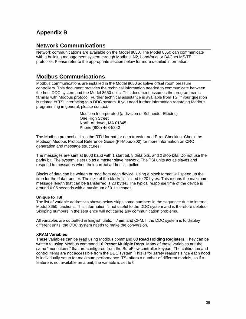
39
Appendix B
Network Communications Network communications are available on the Model 8650. The Model 8650 can communicate with a building management system through Modbus, N2, LonWorks or BACnet MS/TP protocols. Please refer to the appropriate section below for more detailed information.
Modbus Communications Modbus communications are installed in the Model 8650 adaptive offset room pressure controllers. This document provides the technical information needed to communicate between the host DDC system and the Model 8650 units. This document assumes the programmer is familiar with Modbus protocol. Further technical assistance is available from TSI if your question is related to TSI interfacing to a DDC system. If you need further information regarding Modbus programming in general, please contact:
Modicon Incorporated (a division of Schneider-Electric) One High Street North Andover, MA 01845 Phone (800) 468-5342
The Modbus protocol utilizes the RTU format for data transfer and Error Checking. Check the Modicon Modbus Protocol Reference Guide (PI-Mbus-300) for more information on CRC generation and message structures. The messages are sent at 9600 baud with 1 start bit, 8 data bits, and 2 stop bits. Do not use the parity bit. The system is set up as a master slave network. The TSI units act as slaves and respond to messages when their correct address is polled. Blocks of data can be written or read from each device. Using a block format will speed up the time for the data transfer. The size of the blocks is limited to 20 bytes. This means the maximum message length that can be transferred is 20 bytes. The typical response time of the device is around 0.05 seconds with a maximum of 0.1 seconds.
Unique to TSI The list of variable addresses shown below skips some numbers in the sequence due to internal Model 8650 functions. This information is not useful to the DDC system and is therefore deleted. Skipping numbers in the sequence will not cause any communication problems. All variables are outputted in English units: ft/min, and CFM. If the DDC system is to display different units, the DDC system needs to make the conversion.
XRAM Variables These variables can be read using Modbus command 03 Read Holding Registers. They can be
written to using Modbus command 16 Preset Multiple Regs. Many of these variables are the same ―menu items‖ that are configured from the SureFlow controller keypad. The calibration and control items are not accessible from the DDC system. This is for safety reasons since each hood is individually setup for maximum performance. TSI offers a number of different models, so if a feature is not available on a unit, the variable is set to 0.
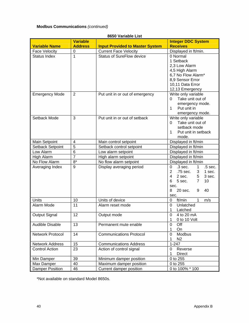
Modbus Communications (continued)
40 Appendix B
8650 Variable List
Variable Name Variable Address Input Provided to Master System
Integer DDC System Receives
Face Velocity 0 Current Face Velocity Displayed in ft/min.
Status Index 1 Status of SureFlow device 0 Normal 1 Setback 2,3 Low Alarm 4,5 High Alarm 6,7 No Flow Alarm* 8,9 Sensor Error 10,11 Data Error 12,13 Emergency
Emergency Mode 2 Put unit in or out of emergency Write only variable 0 Take unit out of
emergency mode. 1 Put unit in
emergency mode.
Setback Mode 3 Put unit in or out of setback Write only variable 0 Take unit out of
setback mode 1 Put unit in setback
mode.
Main Setpoint 4 Main control setpoint Displayed in ft/min
Setback Setpoint 5 Setback control setpoint Displayed in ft/min
Low Alarm 6 Low alarm setpoint Displayed in ft/min
High Alarm 7 High alarm setpoint Displayed in ft/min
No Flow Alarm 8* No flow alarm setpoint Displayed in ft/min
Averaging Index 9 Display averaging period 0 .3 sec. 1 .5 sec. 2 .75 sec. 3 1 sec. 4 2 sec. 5 3 sec. 6 5 sec. 7 10 sec. 8 20 sec. 9 40 sec.
Units 10 Units of device 0 ft/min 1 m/s
Alarm Mode 11 Alarm reset mode 0 Unlatched 1 Latched
Output Signal 12 Output mode 0 4 to 20 mA 1 0 to 10 Volt
Audible Disable 13 Permanent mute enable 0 Off 1 On
Network Protocol 14 Communications Protocol 0 Modbus 1 N2
Network Address 15 Communications Address 1-247
Control Action 23 Action of control signal 0 Reverse 1 Direct
Min Damper 39 Minimum damper position 0 to 255
Max Damper 40 Maximum damper position 0 to 255
Damper Position 46 Current damper position 0 to 100% * 100
*Not available on standard Model 8650s.
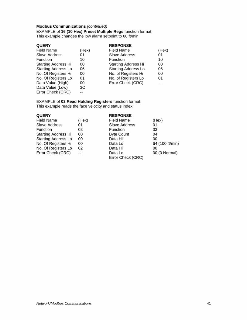
Modbus Communications (continued)
Network/Modbus Communications 41
EXAMPLE of 16 (10 Hex) Preset Multiple Regs function format: This example changes the low alarm setpoint to 60 ft/min
QUERY RESPONSE Field Name (Hex) Field Name (Hex) Slave Address 01 Slave Address 01 Function 10 Function 10 Starting Address Hi 00 Starting Address Hi 00 Starting Address Lo 06 Starting Address Lo 06 No. Of Registers Hi 00 No. of Registers Hi 00 No. Of Registers Lo 01 No. of Registers Lo 01 Data Value (High) 00 Error Check (CRC) -- Data Value (Low) 3C Error Check (CRC) --
EXAMPLE of 03 Read Holding Registers function format: This example reads the face velocity and status index
QUERY RESPONSE Field Name (Hex) Field Name (Hex) Slave Address 01 Slave Address 01 Function 03 Function 03 Starting Address Hi 00 Byte Count 04 Starting Address Lo 00 Data Hi 00 No. Of Registers Hi 00 Data Lo 64 (100 ft/min) No. Of Registers Lo 02 Data Hi 00 Error Check (CRC) -- Data Lo 00 (0 Normal) Error Check (CRC)
42 Appendix B
N2 Communications
Description of Variables
Description of Variables
NPT - Network Point Type Variables are defined as analog inputs, binary inputs, and analog outputs. Analog inputs are current control parameters and items that the controller is measuring. Binary inputs represent controller states. Analog outputs are the programmable setpoints for the face velocity controller. These setpoints can be changed through the keypad or by over-writing the current setpoint.
NPA - Network Point Address Address of the desired point.
Change of Status (COS) - Face Velocity Analog Input The 8650 has the ability to change control setpoints locally. The alarm setpoints need to be based on the controllers control setpoint (AI #2). The unit can be changed from Normal Mode to Setback Mode. For example the setpoint could go from 100 ft/min to 60 ft/min when the Setback key is pressed. If the COS alarm setpoints are not changed to accommodate you could get low alarm or low warning messages when the unit is working correctly. If these alarm points are set outside of the setback and main velocity setpoint values, incorrect alarm messages can be prevented.
Override Analog Input Command Analog Input values can be set using the override command. These values will be reset to the correct items when the Override is released. There is not a time-out on the override command.
Override Binary Input Command Overriding a 1 to the Setback or Emergency binary inputs enables the respective mode. To return the controller to normal mode from setback mode, press the Setback key on the controller, toggle the setback contact input, or release the override. To release controller from emergency state, override a 0 to the Emergency input, toggle the emergency contact input, or press either the emergency or reset key. Releasing the override will return the controller to the state it was in previous to the emergency, either Normal or Setback. The alarm, data error, and sensor error variables can be overridden, but this will not affect the controller. Overriding the low alarm variable will result in a change of status, but will not put the controller into low alarm mode. The local alarm modes can only be controlled locally. Only override these variables for diagnostic purposes, and release them for normal operation.
Binary Inputs, Sensor Error and Data Error Sensor Error and Data Error binary inputs are used to indicate if something has gone wrong with the controller. The Sensor Error is set when the sensor on the controller has a malfunction. This indicates that service should be done on the controller. Data Error indicates when some of the data stored on the device has been corrupted. The calibration and setpoint values should be checked on the controller.
Override Analog Output Command The analog output variables can be overridden to change their values. The overridden value will be checked for validity. If invalid, the override command will be ignored, and the value will not change. The override flag will not be set when the value is ignored. The override command will be cleared when the variable is reset in the menus. The variable will not reset with the release command.
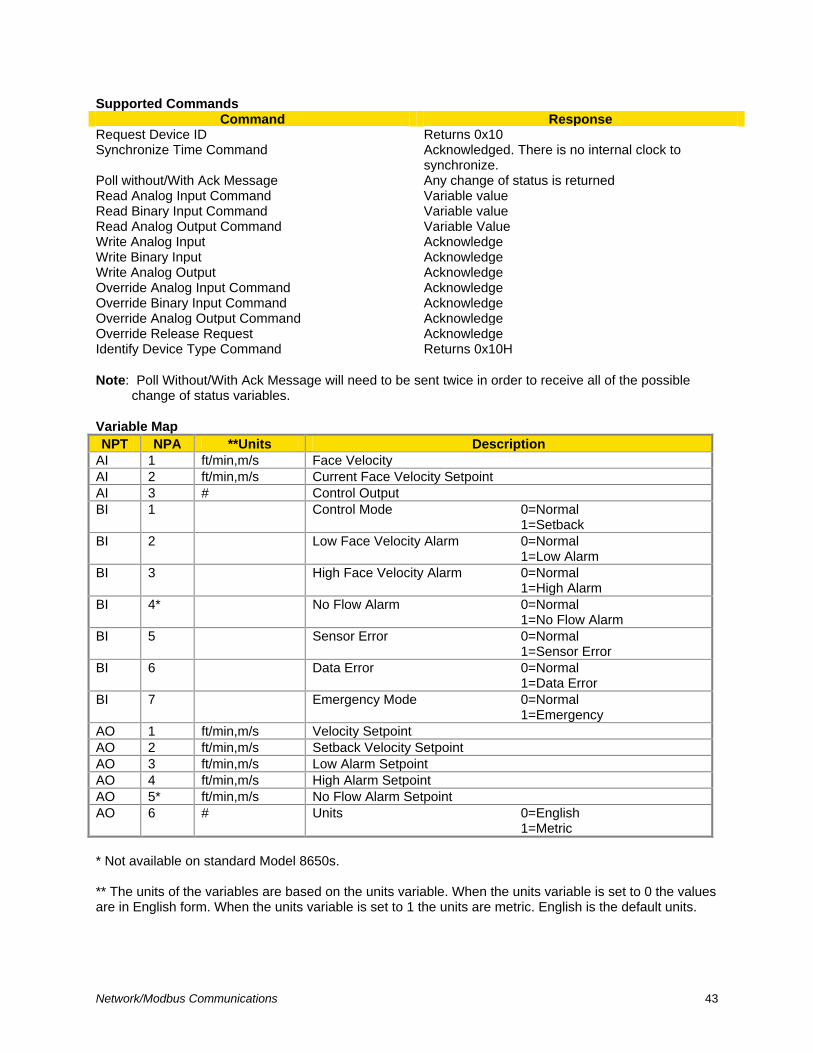
Network/Modbus Communications 43
Supported Commands Command Response
Request Device ID Returns 0x10 Synchronize Time Command Acknowledged. There is no internal clock to
synchronize. Poll without/With Ack Message Any change of status is returned Read Analog Input Command Variable value Read Binary Input Command Variable value Read Analog Output Command Variable Value Write Analog Input Acknowledge Write Binary Input Acknowledge Write Analog Output Acknowledge Override Analog Input Command Acknowledge Override Binary Input Command Acknowledge Override Analog Output Command Acknowledge Override Release Request Acknowledge Identify Device Type Command Returns 0x10H
Note: Poll Without/With Ack Message will need to be sent twice in order to receive all of the possible
change of status variables.
Variable Map
NPT NPA **Units Description
AI 1 ft/min,m/s Face Velocity
AI 2 ft/min,m/s Current Face Velocity Setpoint
AI 3 # Control Output
BI 1 Control Mode 0=Normal 1=Setback
BI 2 Low Face Velocity Alarm 0=Normal 1=Low Alarm
BI 3 High Face Velocity Alarm 0=Normal 1=High Alarm
BI 4* No Flow Alarm 0=Normal 1=No Flow Alarm
BI 5 Sensor Error 0=Normal 1=Sensor Error
BI 6 Data Error 0=Normal 1=Data Error
BI 7 Emergency Mode 0=Normal 1=Emergency
AO 1 ft/min,m/s Velocity Setpoint
AO 2 ft/min,m/s Setback Velocity Setpoint
AO 3 ft/min,m/s Low Alarm Setpoint
AO 4 ft/min,m/s High Alarm Setpoint
AO 5* ft/min,m/s No Flow Alarm Setpoint
AO 6 # Units 0=English 1=Metric
* Not available on standard Model 8650s. ** The units of the variables are based on the units variable. When the units variable is set to 0 the values are in English form. When the units variable is set to 1 the units are metric. English is the default units.
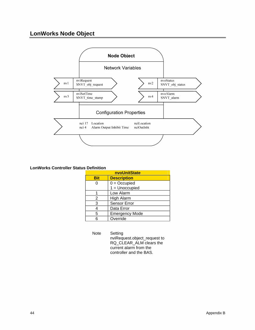
Appendix B 44
LonWorks Node Object
LonWorks Controller Status Definition nvoUnitState
Bit Description
0 0 = Occupied 1 = Unoccupied
1 Low Alarm
2 High Alarm
3 Sensor Error
4 Data Error
5 Emergency Mode
6 Override
Note Setting nviRequest.object_request to RQ_CLEAR_ALM clears the current alarm from the controller and the BAS.
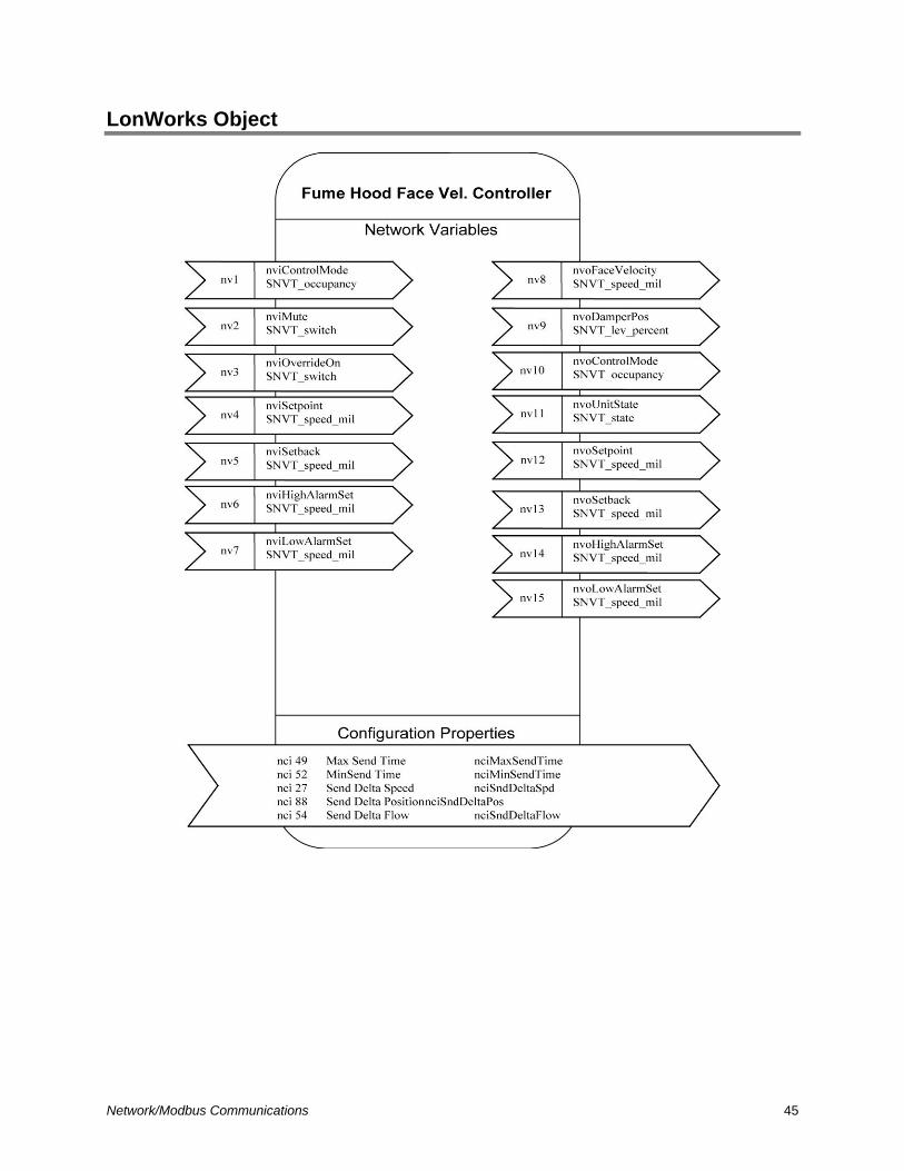
Network/Modbus Communications 45
LonWorks Object
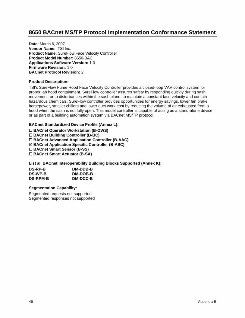
Appendix B 46
8650 BACnet MS/TP Protocol Implementation Conformance Statement Date: March 6, 2007
Vendor Name: TSI Inc.
Product Name: SureFlow Face Velocity Controller
Product Model Number: 8650-BAC
Applications Software Version: 1.0
Firmware Revision: 1.0
BACnet Protocol Revision: 2
Product Description:
TSI's SureFlow Fume Hood Face Velocity Controller provides a closed-loop VAV control system for proper lab hood containment. SureFlow controller assures safety by responding quickly during sash movement, or to disturbances within the sash plane, to maintain a constant face velocity and contain hazardous chemicals. SureFlow controller provides opportunities for energy savings, lower fan brake horsepower, smaller chillers and lower duct work cost by reducing the volume of air exhausted from a hood when the sash is not fully open. This model controller is capable of acting as a stand-alone device or as part of a building automation system via BACnet MS/TP protocol.
BACnet Standardized Device Profile (Annex L):
BACnet Operator Workstation (B-OWS) BACnet Building Controller (B-BC) BACnet Advanced Application Controller (B-AAC) BACnet Application Specific Controller (B-ASC) BACnet Smart Sensor (B-SS) BACnet Smart Actuator (B-SA)
List all BACnet Interoperability Building Blocks Supported (Annex K):
DS-RP-B DM-DDB-B DS-WP-B DM-DOB-B DS-RPM-B DM-DCC-B
Segmentation Capability:
Segmented requests not supported Segmented responses not supported
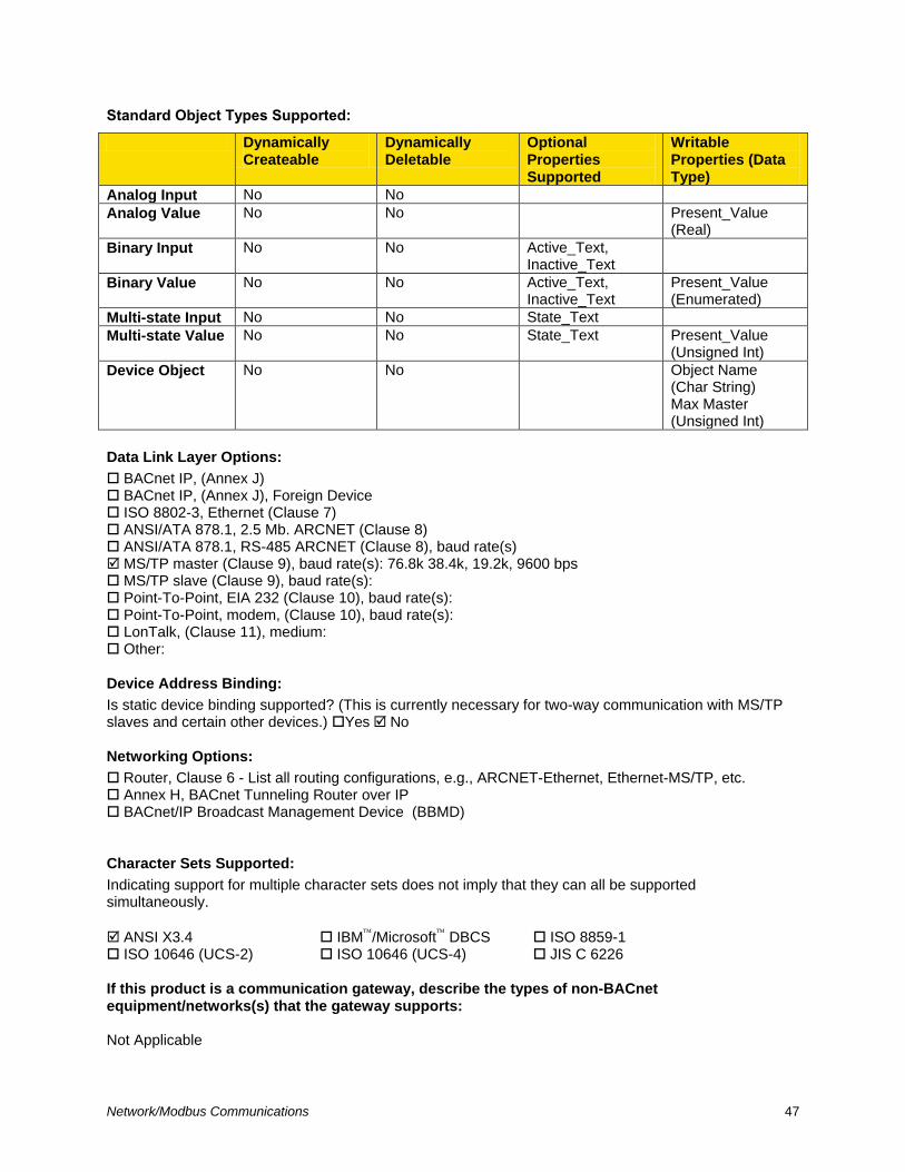
Network/Modbus Communications 47
Standard Object Types Supported:
Dynamically Createable
Dynamically Deletable
Optional Properties Supported
Writable Properties (Data Type)
Analog Input No No
Analog Value No No Present_Value (Real)
Binary Input No No Active_Text, Inactive_Text
Binary Value No No Active_Text, Inactive_Text
Present_Value (Enumerated)
Multi-state Input No No State_Text
Multi-state Value No No State_Text Present_Value (Unsigned Int)
Device Object No No Object Name (Char String) Max Master (Unsigned Int)
Data Link Layer Options:
BACnet IP, (Annex J) BACnet IP, (Annex J), Foreign Device ISO 8802-3, Ethernet (Clause 7) ANSI/ATA 878.1, 2.5 Mb. ARCNET (Clause 8) ANSI/ATA 878.1, RS-485 ARCNET (Clause 8), baud rate(s) MS/TP master (Clause 9), baud rate(s): 76.8k 38.4k, 19.2k, 9600 bps MS/TP slave (Clause 9), baud rate(s): Point-To-Point, EIA 232 (Clause 10), baud rate(s): Point-To-Point, modem, (Clause 10), baud rate(s): LonTalk, (Clause 11), medium: Other:
Device Address Binding:
Is static device binding supported? (This is currently necessary for two-way communication with MS/TP slaves and certain other devices.) Yes No
Networking Options:
Router, Clause 6 - List all routing configurations, e.g., ARCNET-Ethernet, Ethernet-MS/TP, etc. Annex H, BACnet Tunneling Router over IP BACnet/IP Broadcast Management Device (BBMD)
Character Sets Supported:
Indicating support for multiple character sets does not imply that they can all be supported simultaneously.
ANSI X3.4 IBM/Microsoft DBCS ISO 8859-1 ISO 10646 (UCS-2) ISO 10646 (UCS-4) JIS C 6226
If this product is a communication gateway, describe the types of non-BACnet equipment/networks(s) that the gateway supports: Not Applicable
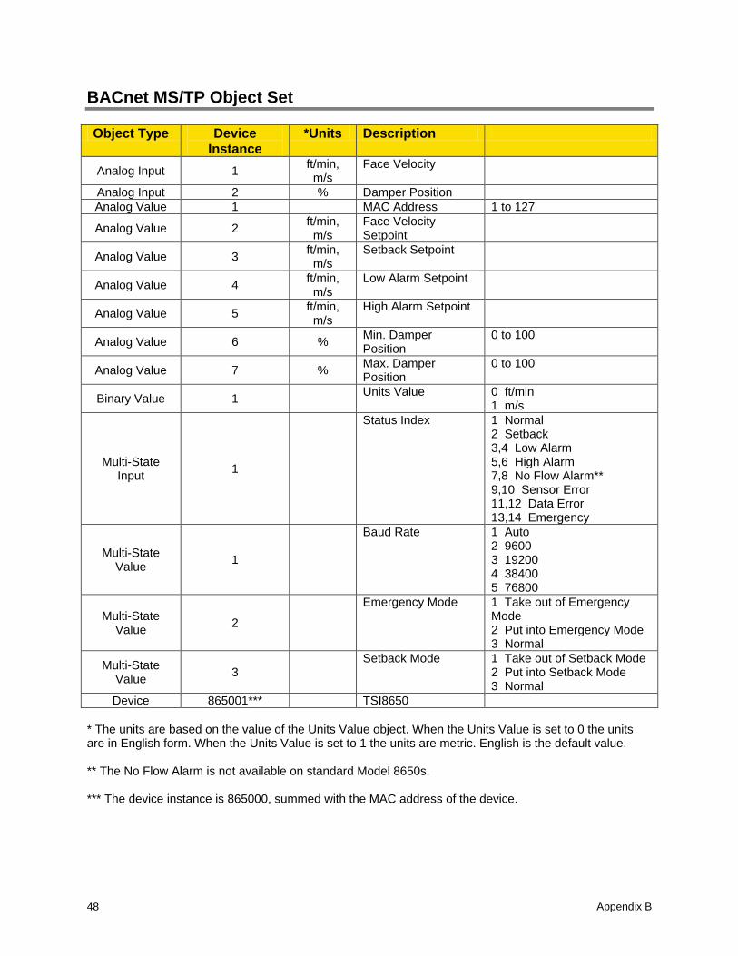
Appendix B 48
BACnet MS/TP Object Set
Object Type Device
Instance
*Units Description
Analog Input 1 ft/min, m/s
Face Velocity
Analog Input 2 % Damper Position
Analog Value 1 MAC Address 1 to 127
Analog Value 2 ft/min, m/s
Face Velocity Setpoint
Analog Value 3 ft/min, m/s
Setback Setpoint
Analog Value 4 ft/min, m/s
Low Alarm Setpoint
Analog Value 5 ft/min, m/s
High Alarm Setpoint
Analog Value 6 % Min. Damper Position
0 to 100
Analog Value 7 % Max. Damper Position
0 to 100
Binary Value 1 Units Value 0 ft/min
1 m/s
Multi-State Input
1
Status Index 1 Normal 2 Setback 3,4 Low Alarm 5,6 High Alarm 7,8 No Flow Alarm** 9,10 Sensor Error 11,12 Data Error 13,14 Emergency
Multi-State Value
1
Baud Rate 1 Auto 2 9600 3 19200 4 38400 5 76800
Multi-State Value
2
Emergency Mode 1 Take out of Emergency Mode 2 Put into Emergency Mode 3 Normal
Multi-State Value
3 Setback Mode 1 Take out of Setback Mode
2 Put into Setback Mode 3 Normal
Device 865001*** TSI8650
* The units are based on the value of the Units Value object. When the Units Value is set to 0 the units are in English form. When the Units Value is set to 1 the units are metric. English is the default value. ** The No Flow Alarm is not available on standard Model 8650s. *** The device instance is 865000, summed with the MAC address of the device.
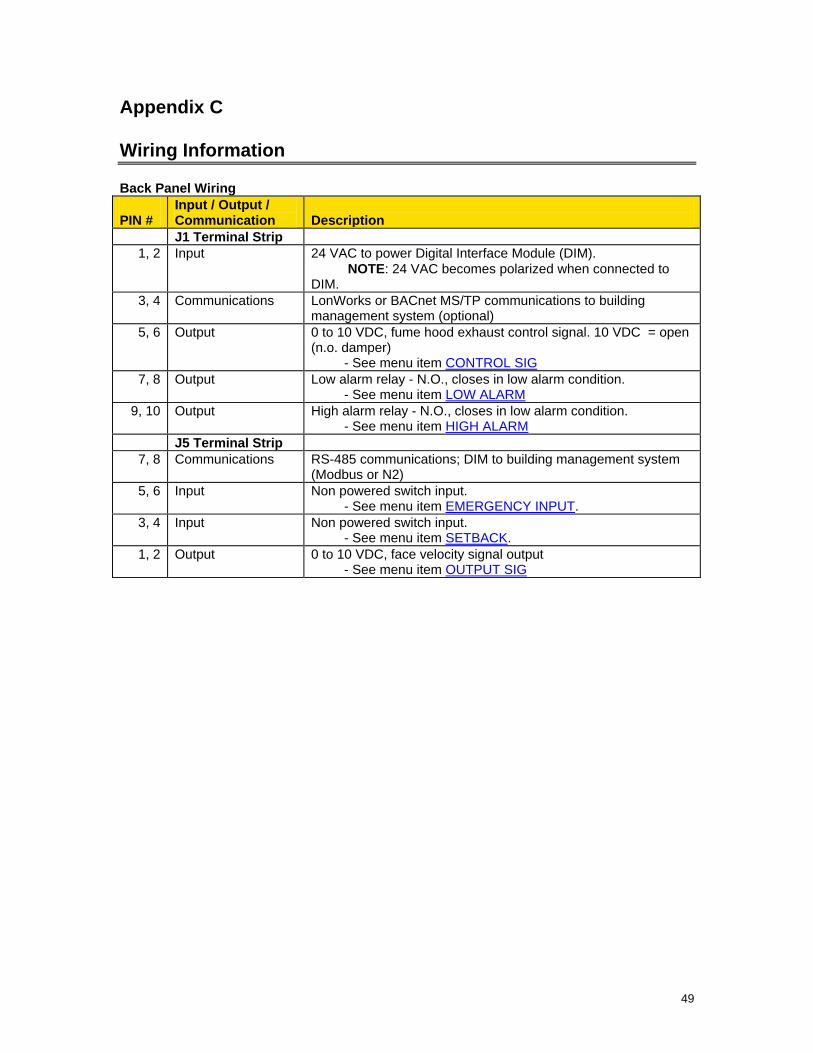
49
Appendix C
Wiring Information
Back Panel Wiring
PIN #
Input / Output / Communication
Description
J1 Terminal Strip
1, 2 Input 24 VAC to power Digital Interface Module (DIM).
NOTE: 24 VAC becomes polarized when connected to DIM.
3, 4 Communications LonWorks or BACnet MS/TP communications to building management system (optional)
5, 6 Output 0 to 10 VDC, fume hood exhaust control signal. 10 VDC = open (n.o. damper) - See menu item CONTROL SIG
7, 8 Output Low alarm relay - N.O., closes in low alarm condition. - See menu item LOW ALARM
9, 10 Output High alarm relay - N.O., closes in low alarm condition. - See menu item HIGH ALARM
J5 Terminal Strip
7, 8 Communications RS-485 communications; DIM to building management system (Modbus or N2)
5, 6 Input Non powered switch input. - See menu item EMERGENCY INPUT.
3, 4 Input Non powered switch input. - See menu item SETBACK.
1, 2 Output 0 to 10 VDC, face velocity signal output - See menu item OUTPUT SIG
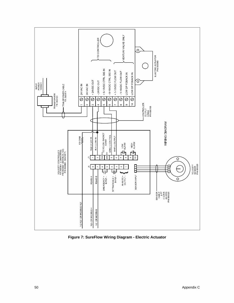
Appendix C 50
Figure 7: SureFlow Wiring Diagram - Electric Actuator
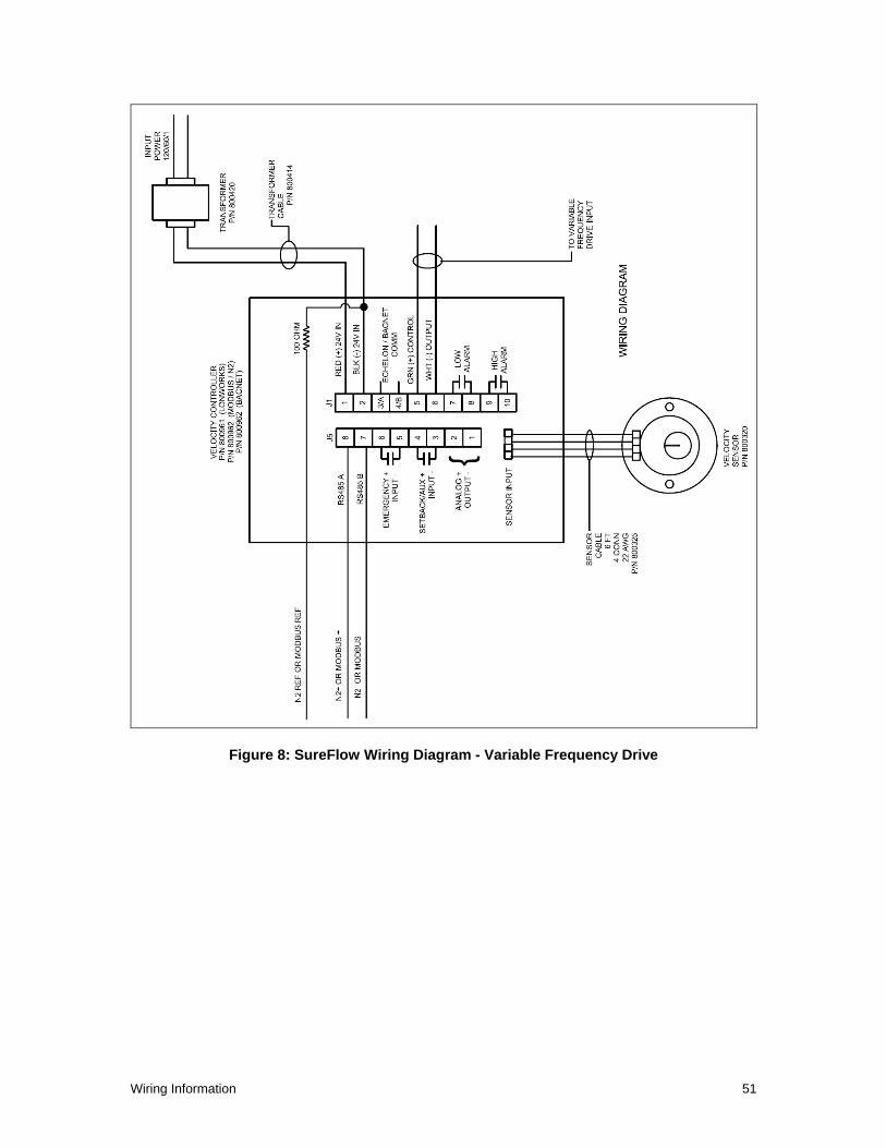
Wiring Information 51
Figure 8: SureFlow Wiring Diagram - Variable Frequency Drive

Appendix C 52
(This page intentionally left blank)
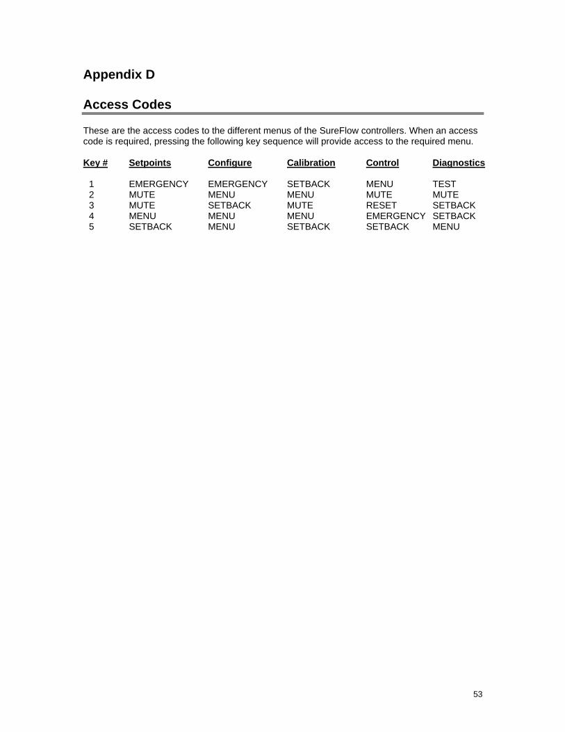
53
Appendix D
Access Codes These are the access codes to the different menus of the SureFlow controllers. When an access code is required, pressing the following key sequence will provide access to the required menu.
Key # Setpoints Configure Calibration Control Diagnostics 1 EMERGENCY EMERGENCY SETBACK MENU TEST 2 MUTE MENU MENU MUTE MUTE 3 MUTE SETBACK MUTE RESET SETBACK 4 MENU MENU MENU EMERGENCY SETBACK 5 SETBACK MENU SETBACK SETBACK MENU

Appendix C 54
(This page intentionally left blank)

TSI Incorporated – Visit our website www.tsi.com for more information. USA Tel: +1 800 874 2811 UK Tel: +44 149 4 459200 France Tel: +33 4 91 11 87 64 Germany Tel: +49 241 523030
India Tel: +91 80 67877200 China Tel: +86 10 8251 6588 Singapore Tel: +65 6595 6388
P/N 1980117 Rev. P ©2013 TSI Incorporated Printed in U.S.A.


