Surface Based Wireless Power Transmission and Bidirectional Communication for Autonomous Robot Swarms Travis Deyle Department of Electrical and Computer Engineering Georgia Institute of Technology Atlanta, Georgia 30332 e-mail: [email protected]Matt Reynolds Department of Electrical and Computer Engineering Duke University Durham, North Carolina 27708 e-mail: [email protected]Abstract—We introduce an inexpensive, low complexity power surface system capable of simultaneously providing wireless power and bidirectional communication from a surface to mul- tiple mobile robots. This system enables continuous operation of a swarm-sized population of battery-less robots. Our first prototype consists of a 60cm x 60cm power surface that provides power and bidirectional communication to an initial evaluation group of five test robots, each one consuming 200mW. Unlike typical non-resonant inductive (transformer) coupling, power transmission in this system is achieved through magnetic flux coupling between a high Q L-C resonator placed beneath the operating surface and a non-resonant pickup coil on each robot. We explore the design of the pickup coil and conditioning circuitry, and we characterize the position-dependent power density of a static load representative of a small autonomous robot operating on the surface. We demonstrate a continuous power density averaging 4.1mW/cm 2 for a static load, and develop much greater peak power for dynamic loads via capacitor storage and power conditioning circuitry. We also demonstrate simultaneous broadcast communication between the surface and all robots via amplitude modulation of the magnetic field, and communication between individual robots and the surface via load modulation. I. I NTRODUCTION Limited onboard power supplies significantly hamper long- term autonomous mobile robot operation, particularly when working with swarm-sized populations. In these situations, battery life usually varies depending on the activity level of each robot. This adversely affects researchers’ ability to test new algorithms and sensor systems both by creating troublesome logistical barriers and preventing the evaluation of large numbers of robots or algorithms with long running times. With swarm robotics, as in mobile robotics in general, robot power budget strongly influences mechanical and electrical design, operational duration, and even behavior. We have been developing methods to enable continuous robot operation by eliminating recharging, battery swapping, and cumbersome tethers altogether. Previous solutions in the literature have relied on tethers, battery exchange, docking or recharging Fig. 1. Swarm Operating Battery-Free on the Power Surface schemes, or specialty power sources such as fuel cells or hy- drocarbon engines. In contrast to these approaches, we propose a low-complexity, inexpensive wireless power system capable of simultaneously providing wireless power and bidirectional communication to a swarm of mobile robots in continuous operation on a bounded surface. We have built and tested a demonstration system consisting of five mobile robots, each drawing 200mW of power from a 60cm x 60cm power surface. We characterize the position dependence of power density on the surface, and demonstrate an average received power density of 4.1mW/cm 2 . In comparison, bright sunlight has a power density of approximately 20mW/cm 2 after typical 20% solar cell conversion efficiency, while indoor light levels are typically 1-2 orders of magnitude less. We also demonstrate simultaneous multicast communication
Transcript
Surface Based Wireless Power Transmission andBidirectional Communication for Autonomous
Robot SwarmsTravis Deyle
Department of Electricaland Computer Engineering
Georgia Institute of TechnologyAtlanta, Georgia 30332
Abstract—We introduce an inexpensive, low complexity powersurface system capable of simultaneously providing wirelesspower and bidirectional communication from a surface to mul-tiple mobile robots. This system enables continuous operation ofa swarm-sized population of battery-less robots.
Our first prototype consists of a 60cm x 60cm power surfacethat provides power and bidirectional communication to an initialevaluation group of five test robots, each one consuming 200mW.
Unlike typical non-resonant inductive (transformer) coupling,power transmission in this system is achieved through magneticflux coupling between a high Q L-C resonator placed beneaththe operating surface and a non-resonant pickup coil on eachrobot. We explore the design of the pickup coil and conditioningcircuitry, and we characterize the position-dependent powerdensity of a static load representative of a small autonomousrobot operating on the surface. We demonstrate a continuouspower density averaging 4.1mW/cm2 for a static load, anddevelop much greater peak power for dynamic loads via capacitorstorage and power conditioning circuitry. We also demonstratesimultaneous broadcast communication between the surface andall robots via amplitude modulation of the magnetic field, andcommunication between individual robots and the surface viaload modulation.
I. INTRODUCTION
Limited onboard power supplies significantly hamper long-term autonomous mobile robot operation, particularly whenworking with swarm-sized populations. In these situations,battery life usually varies depending on the activity levelof each robot. This adversely affects researchers’ ability totest new algorithms and sensor systems both by creatingtroublesome logistical barriers and preventing the evaluationof large numbers of robots or algorithms with long runningtimes.
With swarm robotics, as in mobile robotics in general, robotpower budget strongly influences mechanical and electricaldesign, operational duration, and even behavior. We have beendeveloping methods to enable continuous robot operation byeliminating recharging, battery swapping, and cumbersometethers altogether. Previous solutions in the literature haverelied on tethers, battery exchange, docking or recharging
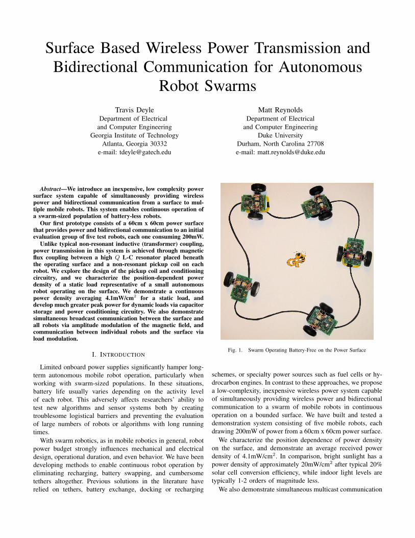
Fig. 1. Swarm Operating Battery-Free on the Power Surface
schemes, or specialty power sources such as fuel cells or hy-drocarbon engines. In contrast to these approaches, we proposea low-complexity, inexpensive wireless power system capableof simultaneously providing wireless power and bidirectionalcommunication to a swarm of mobile robots in continuousoperation on a bounded surface. We have built and tested ademonstration system consisting of five mobile robots, eachdrawing 200mW of power from a 60cm x 60cm power surface.
We characterize the position dependence of power densityon the surface, and demonstrate an average received powerdensity of 4.1mW/cm2. In comparison, bright sunlight has apower density of approximately 20mW/cm2 after typical 20%solar cell conversion efficiency, while indoor light levels aretypically 1-2 orders of magnitude less.
We also demonstrate simultaneous multicast communication
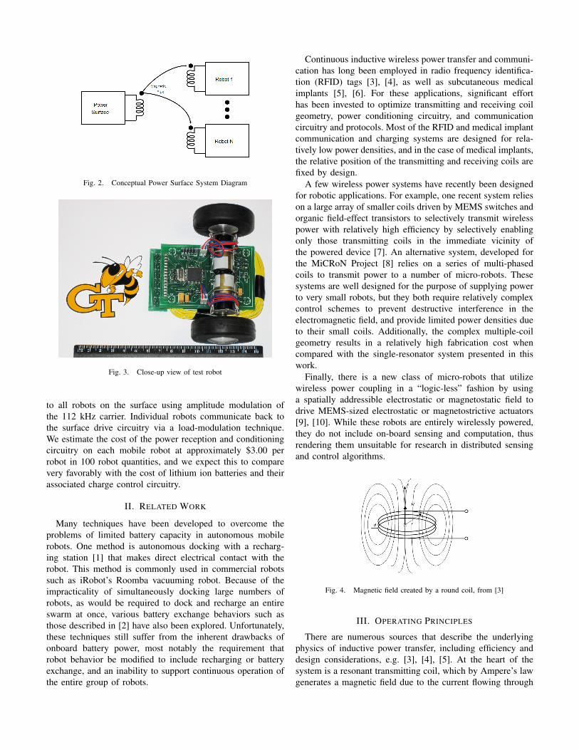
Fig. 2. Conceptual Power Surface System Diagram
Fig. 3. Close-up view of test robot
to all robots on the surface using amplitude modulation ofthe 112 kHz carrier. Individual robots communicate back tothe surface drive circuitry via a load-modulation technique.We estimate the cost of the power reception and conditioningcircuitry on each mobile robot at approximately $3.00 perrobot in 100 robot quantities, and we expect this to comparevery favorably with the cost of lithium ion batteries and theirassociated charge control circuitry.
II. RELATED WORK
Many techniques have been developed to overcome theproblems of limited battery capacity in autonomous mobilerobots. One method is autonomous docking with a recharg-ing station [1] that makes direct electrical contact with therobot. This method is commonly used in commercial robotssuch as iRobot’s Roomba vacuuming robot. Because of theimpracticality of simultaneously docking large numbers ofrobots, as would be required to dock and recharge an entireswarm at once, various battery exchange behaviors such asthose described in [2] have also been explored. Unfortunately,these techniques still suffer from the inherent drawbacks ofonboard battery power, most notably the requirement thatrobot behavior be modified to include recharging or batteryexchange, and an inability to support continuous operation ofthe entire group of robots.
Continuous inductive wireless power transfer and communi-cation has long been employed in radio frequency identifica-tion (RFID) tags [3], [4], as well as subcutaneous medicalimplants [5], [6]. For these applications, significant efforthas been invested to optimize transmitting and receiving coilgeometry, power conditioning circuitry, and communicationcircuitry and protocols. Most of the RFID and medical implantcommunication and charging systems are designed for rela-tively low power densities, and in the case of medical implants,the relative position of the transmitting and receiving coils arefixed by design.
A few wireless power systems have recently been designedfor robotic applications. For example, one recent system relieson a large array of smaller coils driven by MEMS switches andorganic field-effect transistors to selectively transmit wirelesspower with relatively high efficiency by selectively enablingonly those transmitting coils in the immediate vicinity ofthe powered device [7]. An alternative system, developed forthe MiCRoN Project [8] relies on a series of multi-phasedcoils to transmit power to a number of micro-robots. Thesesystems are well designed for the purpose of supplying powerto very small robots, but they both require relatively complexcontrol schemes to prevent destructive interference in theelectromagnetic field, and provide limited power densities dueto their small coils. Additionally, the complex multiple-coilgeometry results in a relatively high fabrication cost whencompared with the single-resonator system presented in thiswork.
Finally, there is a new class of micro-robots that utilizewireless power coupling in a “logic-less” fashion by usinga spatially addressible electrostatic or magnetostatic field todrive MEMS-sized electrostatic or magnetostrictive actuators[9], [10]. While these robots are entirely wirelessly powered,they do not include on-board sensing and computation, thusrendering them unsuitable for research in distributed sensingand control algorithms.
Fig. 4. Magnetic field created by a round coil, from [3]
III. OPERATING PRINCIPLES
There are numerous sources that describe the underlyingphysics of inductive power transfer, including efficiency anddesign considerations, e.g. [3], [4], [5]. At the heart of thesystem is a resonant transmitting coil, which by Ampere’s lawgenerates a magnetic field due to the current flowing through
each turn of wire. The current I flowing through a round coilof radius r results in a magnetic field strength H at a certaindistance x from the center of the coil given by
H(x) =I ·Nt · r2
2√
(r2 + x2)3(1)
where I is the circulating current in the transmitting coil,and Nt is the number of turns in the transmitting coil. Thegeometry used in this expression is shown in Figure 4.
Because the transmitting coil is resonant, the circulatingcurrent in the transmitting coil is larger by Q than the drivecurrent supplied to the coil. In our 60cm x 60cm powersurface, the transmitting coil has 23 turns, a measured in-ductance of 740µH, and a measured DC resistance of 0.42Ω.At the operating frequency of 112KHz, the calculated coilQ = 2πfL/R = 1240. Losses in the mica resonatingcapacitors as well as in proximate materials limit the loadedQ of the resonant circuit to a measured value of Q ≈ 117.
When the transmitting coil is much larger than the pickupcoil, as in our power surface where the transmitting coil hasan area of 3600cm2 while the pickup coil has an area of only78.5cm2, we can assume to a first order that H is uniformwithin the pickup coil, although H is definitely not uniformas the pickup coil is moved about on the power surface. Themagnetic field H induces an electric potential E across thenon-resonant pickup coil given by Faraday’s law:
E = µ0HωNpAp (2)
where µ0 = 4π · 10−7H/m, Np is the number of turns in thepickup coil, ω is the operating frequency, and Ap is the areaof the pickup coil.
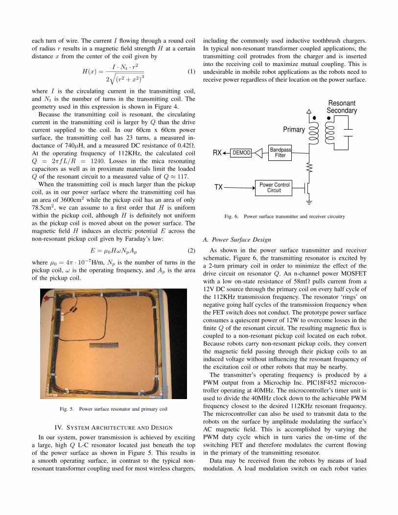
Fig. 5. Power surface resonator and primary coil
IV. SYSTEM ARCHITECTURE AND DESIGN
In our system, power transmission is achieved by excitinga large, high Q L-C resonator located just beneath the topof the power surface as shown in Figure 5. This results ina smooth operating surface, in contrast to the typical non-resonant transformer coupling used for most wireless chargers,
including the commonly used inductive toothbrush chargers.In typical non-resonant transformer coupled applications, thetransmitting coil protrudes from the charger and is insertedinto the receiving coil to maximize mutual coupling. This isundesirable in mobile robot applications as the robots need toreceive power regardless of their location on the power surface.
Power ControlCircuit
BandpassFilterRX DEMOD
TX
Primary
ResonantSecondary
Fig. 6. Power surface transmitter and receiver circuitry
A. Power Surface Design
As shown in the power surface transmitter and receiverschematic, Figure 6, the transmitting resonator is excited bya 2-turn primary coil in order to minimize the effect of thedrive circuit on resonator Q. An n-channel power MOSFETwith a low on-state resistance of 58mΩ pulls current from a12V DC source through the primary coil on every half cycle ofthe 112KHz transmission frequency. The resonator ‘rings’ onnegative going half cycles of the transmission frequency whenthe FET switch does not conduct. The prototype power surfaceconsumes a quiescent power of 12W to overcome losses in thefinite Q of the resonant circuit. The resulting magnetic flux iscoupled to a non-resonant pickup coil located on each robot.Because robots carry non-resonant pickup coils, they convertthe magnetic field passing through their pickup coils to aninduced voltage without influencing the resonant frequency ofthe excitation coil or other robots that may be nearby.
The transmitter’s operating frequency is produced by aPWM output from a Microchip Inc. PIC18F452 microcon-troller operating at 40MHz. The microcontroller’s timer unit isused to divide the 40MHz clock down to the achievable PWMfrequency closest to the desired 112KHz resonant frequency.The microcontroller can also be used to transmit data to therobots on the surface by amplitude modulating the surface’sAC magnetic field. This is accomplished by varying thePWM duty cycle which in turn varies the on-time of theswitching FET and therefore modulates the current flowingin the primary of the transmitting resonator.
Data may be received from the robots by means of loadmodulation. A load modulation switch on each robot varies
the amount of current drawn from the surface. An envelopedetector in the power surface controller detects the loadmodulation, which is filtered by an op-amp based active filter,amplified, and thresholded to present a data signal to thesurface controller’s microcontroller.
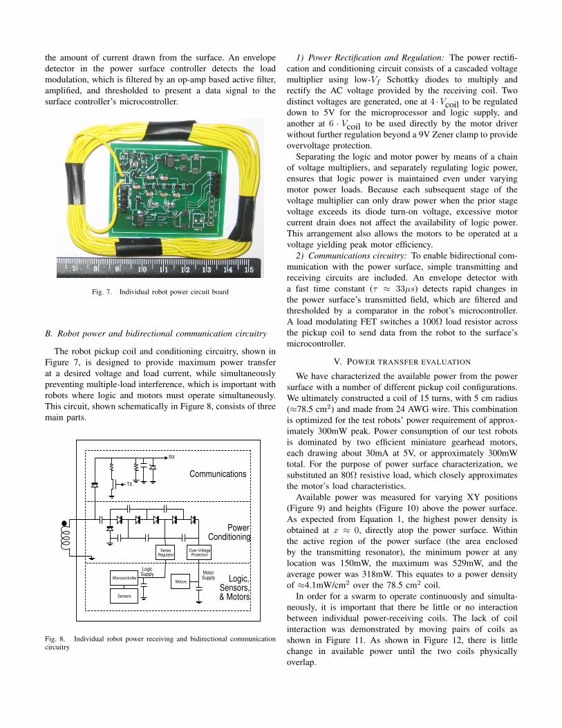
Fig. 7. Individual robot power circuit board
B. Robot power and bidirectional communication circuitry
The robot pickup coil and conditioning circuitry, shown inFigure 7, is designed to provide maximum power transferat a desired voltage and load current, while simultaneouslypreventing multiple-load interference, which is important withrobots where logic and motors must operate simultaneously.This circuit, shown schematically in Figure 8, consists of threemain parts.
TX
RX
SeriesRegulator
Microcontroller
Sensors
Over-VoltageProtection
LogicSupply Motor
SupplyMotors
Communications
PowerConditioning
Logic,Sensors,& Motors
Fig. 8. Individual robot power receiving and bidirectional communicationcircuitry
1) Power Rectification and Regulation: The power rectifi-cation and conditioning circuit consists of a cascaded voltagemultiplier using low-Vf Schottky diodes to multiply andrectify the AC voltage provided by the receiving coil. Twodistinct voltages are generated, one at 4 ·Vcoil to be regulateddown to 5V for the microprocessor and logic supply, andanother at 6 · Vcoil to be used directly by the motor driverwithout further regulation beyond a 9V Zener clamp to provideovervoltage protection.
Separating the logic and motor power by means of a chainof voltage multipliers, and separately regulating logic power,ensures that logic power is maintained even under varyingmotor power loads. Because each subsequent stage of thevoltage multiplier can only draw power when the prior stagevoltage exceeds its diode turn-on voltage, excessive motorcurrent drain does not affect the availability of logic power.This arrangement also allows the motors to be operated at avoltage yielding peak motor efficiency.
2) Communications circuitry: To enable bidirectional com-munication with the power surface, simple transmitting andreceiving circuits are included. An envelope detector witha fast time constant (τ ≈ 33µs) detects rapid changes inthe power surface’s transmitted field, which are filtered andthresholded by a comparator in the robot’s microcontroller.A load modulating FET switches a 100Ω load resistor acrossthe pickup coil to send data from the robot to the surface’smicrocontroller.
V. POWER TRANSFER EVALUATION
We have characterized the available power from the powersurface with a number of different pickup coil configurations.We ultimately constructed a coil of 15 turns, with 5 cm radius(≈78.5 cm2) and made from 24 AWG wire. This combinationis optimized for the test robots’ power requirement of approx-imately 300mW peak. Power consumption of our test robotsis dominated by two efficient miniature gearhead motors,each drawing about 30mA at 5V, or approximately 300mWtotal. For the purpose of power surface characterization, wesubstituted an 80Ω resistive load, which closely approximatesthe motor’s load characteristics.
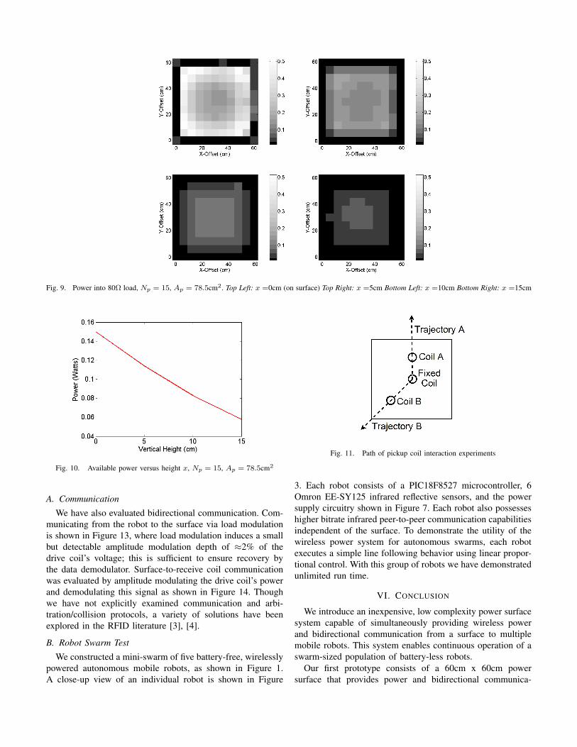
Available power was measured for varying XY positions(Figure 9) and heights (Figure 10) above the power surface.As expected from Equation 1, the highest power density isobtained at x ≈ 0, directly atop the power surface. Withinthe active region of the power surface (the area enclosedby the transmitting resonator), the minimum power at anylocation was 150mW, the maximum was 529mW, and theaverage power was 318mW. This equates to a power densityof ≈4.1mW/cm2 over the 78.5 cm2 coil.
In order for a swarm to operate continuously and simulta-neously, it is important that there be little or no interactionbetween individual power-receiving coils. The lack of coilinteraction was demonstrated by moving pairs of coils asshown in Figure 11. As shown in Figure 12, there is littlechange in available power until the two coils physicallyoverlap.
Fig. 9. Power into 80Ω load, Np = 15, Ap = 78.5cm2. Top Left: x =0cm (on surface) Top Right: x =5cm Bottom Left: x =10cm Bottom Right: x =15cm
Fig. 10. Available power versus height x, Np = 15, Ap = 78.5cm2
A. Communication
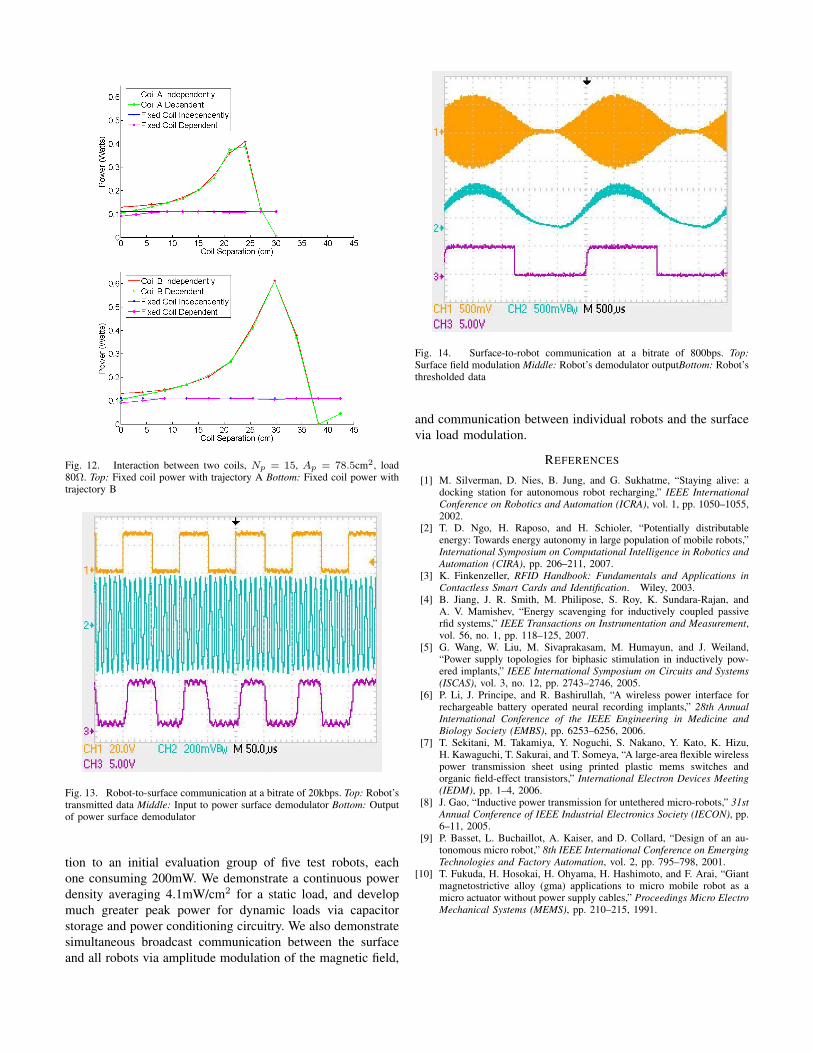
We have also evaluated bidirectional communication. Com-municating from the robot to the surface via load modulationis shown in Figure 13, where load modulation induces a smallbut detectable amplitude modulation depth of ≈2% of thedrive coil’s voltage; this is sufficient to ensure recovery bythe data demodulator. Surface-to-receive coil communicationwas evaluated by amplitude modulating the drive coil’s powerand demodulating this signal as shown in Figure 14. Thoughwe have not explicitly examined communication and arbi-tration/collision protocols, a variety of solutions have beenexplored in the RFID literature [3], [4].
B. Robot Swarm Test
We constructed a mini-swarm of five battery-free, wirelesslypowered autonomous mobile robots, as shown in Figure 1.A close-up view of an individual robot is shown in Figure
Fig. 11. Path of pickup coil interaction experiments
3. Each robot consists of a PIC18F8527 microcontroller, 6Omron EE-SY125 infrared reflective sensors, and the powersupply circuitry shown in Figure 7. Each robot also possesseshigher bitrate infrared peer-to-peer communication capabilitiesindependent of the surface. To demonstrate the utility of thewireless power system for autonomous swarms, each robotexecutes a simple line following behavior using linear propor-tional control. With this group of robots we have demonstratedunlimited run time.
VI. CONCLUSION
We introduce an inexpensive, low complexity power surfacesystem capable of simultaneously providing wireless powerand bidirectional communication from a surface to multiplemobile robots. This system enables continuous operation of aswarm-sized population of battery-less robots.
Our first prototype consists of a 60cm x 60cm powersurface that provides power and bidirectional communica-
Fig. 12. Interaction between two coils, Np = 15, Ap = 78.5cm2, load80Ω. Top: Fixed coil power with trajectory A Bottom: Fixed coil power withtrajectory B
Fig. 13. Robot-to-surface communication at a bitrate of 20kbps. Top: Robot’stransmitted data Middle: Input to power surface demodulator Bottom: Outputof power surface demodulator
tion to an initial evaluation group of five test robots, eachone consuming 200mW. We demonstrate a continuous powerdensity averaging 4.1mW/cm2 for a static load, and developmuch greater peak power for dynamic loads via capacitorstorage and power conditioning circuitry. We also demonstratesimultaneous broadcast communication between the surfaceand all robots via amplitude modulation of the magnetic field,
Fig. 14. Surface-to-robot communication at a bitrate of 800bps. Top:Surface field modulation Middle: Robot’s demodulator outputBottom: Robot’sthresholded data
and communication between individual robots and the surfacevia load modulation.
REFERENCES
[1] M. Silverman, D. Nies, B. Jung, and G. Sukhatme, “Staying alive: adocking station for autonomous robot recharging,” IEEE InternationalConference on Robotics and Automation (ICRA), vol. 1, pp. 1050–1055,2002.
[2] T. D. Ngo, H. Raposo, and H. Schioler, “Potentially distributableenergy: Towards energy autonomy in large population of mobile robots,”International Symposium on Computational Intelligence in Robotics andAutomation (CIRA), pp. 206–211, 2007.
[3] K. Finkenzeller, RFID Handbook: Fundamentals and Applications inContactless Smart Cards and Identification. Wiley, 2003.
[4] B. Jiang, J. R. Smith, M. Philipose, S. Roy, K. Sundara-Rajan, andA. V. Mamishev, “Energy scavenging for inductively coupled passiverfid systems,” IEEE Transactions on Instrumentation and Measurement,vol. 56, no. 1, pp. 118–125, 2007.
[5] G. Wang, W. Liu, M. Sivaprakasam, M. Humayun, and J. Weiland,“Power supply topologies for biphasic stimulation in inductively pow-ered implants,” IEEE International Symposium on Circuits and Systems(ISCAS), vol. 3, no. 12, pp. 2743–2746, 2005.
[6] P. Li, J. Principe, and R. Bashirullah, “A wireless power interface forrechargeable battery operated neural recording implants,” 28th AnnualInternational Conference of the IEEE Engineering in Medicine andBiology Society (EMBS), pp. 6253–6256, 2006.
[7] T. Sekitani, M. Takamiya, Y. Noguchi, S. Nakano, Y. Kato, K. Hizu,H. Kawaguchi, T. Sakurai, and T. Someya, “A large-area flexible wirelesspower transmission sheet using printed plastic mems switches andorganic field-effect transistors,” International Electron Devices Meeting(IEDM), pp. 1–4, 2006.
[8] J. Gao, “Inductive power transmission for untethered micro-robots,” 31stAnnual Conference of IEEE Industrial Electronics Society (IECON), pp.6–11, 2005.
[9] P. Basset, L. Buchaillot, A. Kaiser, and D. Collard, “Design of an au-tonomous micro robot,” 8th IEEE International Conference on EmergingTechnologies and Factory Automation, vol. 2, pp. 795–798, 2001.
[10] T. Fukuda, H. Hosokai, H. Ohyama, H. Hashimoto, and F. Arai, “Giantmagnetostrictive alloy (gma) applications to micro mobile robot as amicro actuator without power supply cables,” Proceedings Micro ElectroMechanical Systems (MEMS), pp. 210–215, 1991.