Page 1
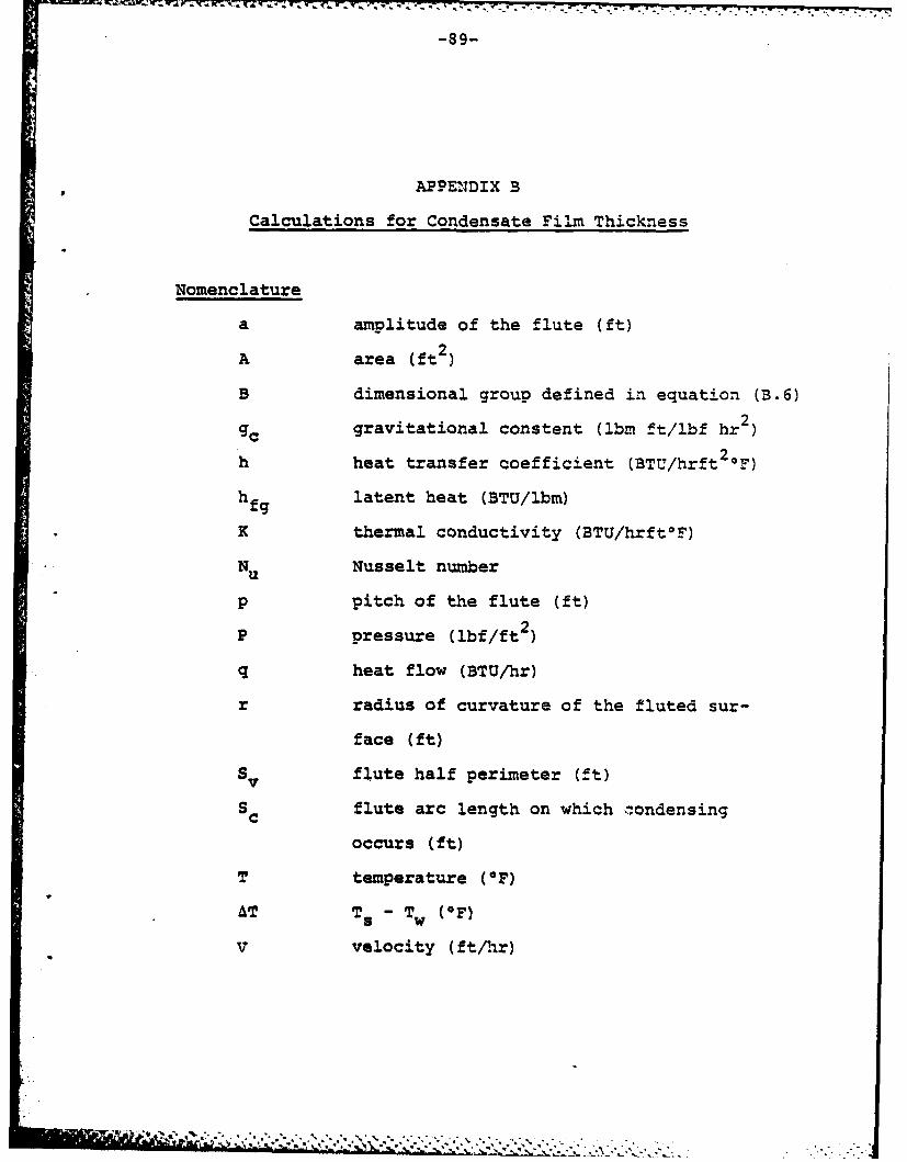
i-Ai34 063 MARINE SURFACE CONDENSER DESIGN USING VERTICAL TUBES 112WHICH ARE ENHANCED(U) NAVAL POSTGRADUATE SCHOOLMONTEREY CR C G BARNES JUN 81
UNCLASSIFIED F/6 13/1i N
EEEmohEohEEmiEEohEEEEEmhhhhEEhhmhEEmhEmhEIEhEEEEEE-EmohEsmmhohEEEEEEEE
Page 2
1111113W2 2
11111 ~ 1W 8
111.25 14 =6
MICROCOPY RESOLUTION TEST CHARTNATIONAL BUREAU OF STANDARDS-1963-A
Page 3
sEcuouvv CLASSIFICAION or THIS PAQE (.M ow. em ___________________
REPORT DOCUMENTATiON PAGE sRoAD COMPLETIfN OR
a ifters"ubms.. .,A3 .,.3 S. via0 OEFOREPCORPTIN a Pe OVRD
* ?~MARMN SUflFM CMCJqER EMQN USING VEI(*...WHE ~ICH AF NACD THEIS
a. PIRPOmuIGg amG. REPORT Owmmgrn
d -. Au TOMM.Al . ema 6A eWfS(sj
I BAmm, amMMD~ G., JR.MI.PSGAE~Ey.NJ~ a
CAMRIC=, MA, 02139
It. CONTROLLIN rr "m~ee AEAND aOSOESS 1. mEPORT DATE___ OM 031 JN8
NAVATL -~TAA1 SCOXI is. "uman OF PAGES
?OREER~ !, Ch 93940 125 ON vo r wI-TAL-war aOORN m4lC IOM A 46inmum. 400000 *41 OI 6CmITv CLASS. (Of 0e uw
APRO MR PEWLC IMMM; DISPAMMY!7D1 KRLM1rm
IS. suP9LabeuNaRIF NOTES
19. leg 90oene caesmu. -s revese Ot of mem On -ee o mam
MMM a2IMMSR 03SIGNVEMCaB TM CCNCEES
ISO A&SWUAC? fddllinO - s's... . it MMMOOMF sd Mi"M AV 601141 inS's
-.j
- .. JO017
Page 4
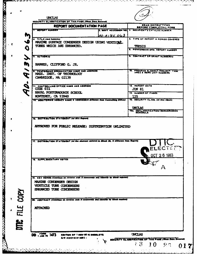
ABSTRACT
A methodology is developed for calculating the heattransfer coefficient on the surface of a vertical flutedcondenser tube based upon condensate film thickness. Amarine condenser sizing procedure is demonstrated usingthis methodology. A comparison is made between a flutedtube condenser and a comparable smooth tube horizontalcondenser. Alternative materials are considered andapplicability is assessed for submarine use.
The results of the analysis indicate that a smallervolume, lighter weight condenser can be designed formarine use. The marine enginee- can specify tube lengthor condensate drainage rate and size the condenser ac-cordingly. Approximately 20% can be saved in volume, and,by using Titanium in place of Copper-Nickel, approximately30% can be saved in tube bundle weight, compared to asimilar horizontal condenser.
00 ?ewu 1473 WA,r49a-V fe ! .a.. . TMS Pa O" t "s &
"I- " . ,*j . .. ._
Page 5
Approved for publio rejea.S.distr-bution unlimited.
M1ARINE SURFACE CONDENSER DESIGN USING
VERTICAL TUBES ?MICH ARE ENHANCED
by
CLIFFORD GERALD BARNES, JR.LIEUTENANT, US NAVY
B.S., United States tilitary Academy(1974)
Submitted in Partial Fulfillmentof the Requirements of the Degrees of
OCEAN ENGINEER
and
MASTER OF SCIENCE IN MECHANICAL ENGINEERING
at the
MASSACHUSETTS INSTITUTE OF TECHNOLOGY
May 1981
@ Clifford G. Barnes, Jr.
The author hereby grants to M.I.T. permissionto reproduce and to distribute copies of this
thesis document in whole or in part.
Signature of Author: ci/ I ., ' -Department of ean Engineering,, May 1981
Certified by: U.Warreh I. Rolsenow, Thesis Supervisor
Accepted by.: - A , ,Chairman, Ocean Enqaneering Dyrtmental Committee
.1 z1" I
Accepted by: '1 / - .--. ,:.-.--Chairman, Miechanical Engineering Deparment Committee
li ,.,'i,. , ,,,, .. . . . . . .. 4 ., . . . -..
Page 6
-2-
MARINE SURFACE CONDENSER DESIGN
USING VERTICAL TUBES
WHICH A10 ENHANCED
by
CLIFFORD Cr-RALD BARNES, JR.LIEUTENANT, U.S. NAVY
Submitted to the Department of Ocean Engineeringon 8 May 1981 in partial fulfillment of therequirements of the Degrees of Ocean Engineerand Master of Science in Mechanical Engineering.
ABSTRACT
A methodology is developed for calculating the heattransfer coefficient on the surface of a vertical flutedcondenser tube based upon condensate film thickness. Amarine condenser sizing procedure is demonstrated usingthis methodology. A comparison is made between a flutedtube condenser and a comparable smooth tube horizontalcondwer. Alternative materials are considered andapplicability is assessed for submarine use.
The results of the analysis indicate that a smallervolume, lighter weight condenser can be designed formarine use. The marine engineer can specify tube lengthor condensate drainage rate and size the condenser ac-cordingly. Approximately 20% can be saved in volume, and,by using Titanium in place of Copper-Nickel, approximately30% can be saved in tube bundle weight, compared to asimilar horizontal condenser.
Thesis Supervisor: Warren M. RohsenowTitle: Professor of Mechanical Engineering
i I . . .. 'A% % ,. :. . . ,. . . . .. .. { . . ..... . '
Page 7
-3-
To my brother, David
Page 8
ACKN4OLEDGIMENTS
The author wishes to express his appreciation to
and respect for Professor Warren M. Rohsenow. Without
his guidance and patience this thesis would still be an
idea.
Thanks are due to CDR William Marsh, USN, Professor
Paul Marto, Professor Kenneth Bell, and Dr. John Michele
for collectively launching this effort with timely and
seasoned advice.
A special measure of gratitude is reserved for the
United States Navy, in which I proudly serve, for sup-
porting my education and for never easing the pressure
to succeed.
Page 9
TABLE OF CONTENTS
Pace
ABSTRACT . . . . ...................... 2
ACKNOWLEDGEMEN'TS ................... 4
TABLE OF CONTENTS *.... ..... ..... 5
LIST-OF FIGURES *.... .... .... ...*
LIST OF TABLES . . . . ..................... 8
CHAPTER I. INTRODUCTION .................. 9
I.A. Background Information ... ....... 9I.B. Objectives of This Work . . . 12I.C. Design Inputs .. ........... 17
CHAPTER II. TUBE SELECTION .... ............. . 22
II.A. Materials . . . ........... 22II.B. Strength Requirements .......... .. 29
CHAPTER III. ELEMENTS OF HEAT TRANSFER ......... ... 33
Nomenclature ............ . 33III.A. Heat Transfer Coefficient of
Cooling Water .... *.............36III.B. Heat Transfer Coefficient for
a Tube Wall . .. ................ 37III.C. Heat Transfer Coefficient for
Condensation . . . . . . . . . . 38III.D. Application to Condenser Design- 55III.E. Heat Transfer Resistance Due to
Scaling . .............. 61
CHAPTER IV. DESIGN PROPOSALS ............ 64
IV.A. Condenser Geometry . . . . . . . .. 64IV.B. Tube Attachment* .............. 66
CHAPTER V. RESLLTS AND CONCLUSIONS ......... . 68
V.A. Comparison with Nusselt Analysis • . 68, V.B. Condenser Comparison Using
Titanium . . . . . . . . . .... 69V.C. Conclusions . . .......... 74V.D. Recommendations ................ 76V.E. Summary - .............. 78
APPENDIX A. CONDENSER TUBE STRESS CALCULATIONS . . . 79
Page 10
-'6-
Pace
APPENDIX B. CALCULATIONS FOR CONDENSATE FIU!THICKNESS . . . . . . . .. . . .. . . 89
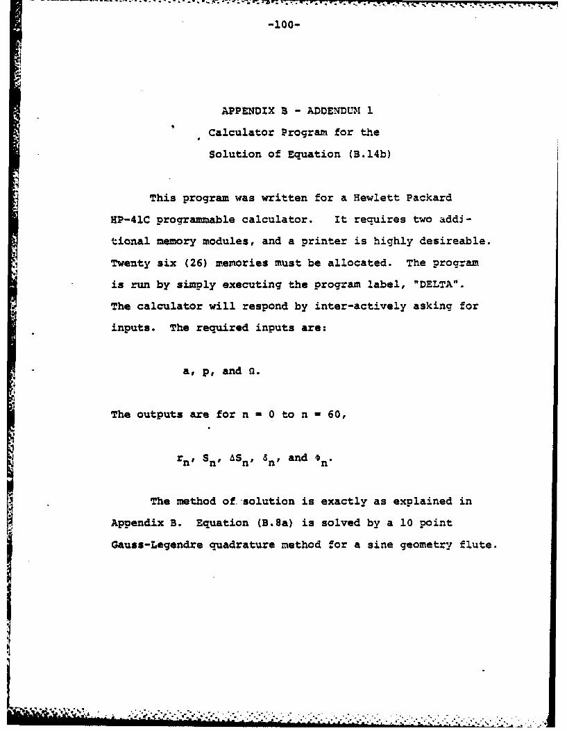
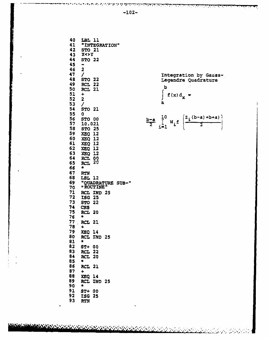
APPENDIX B, ADDENDUM 1. Calculator Program forthe solution of Equation (B.14b) . . . 100
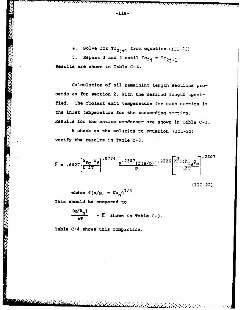
APPENDIX C. FLUTED CONDENSER SIZING PROCEDURE . . . 110
REFERENCES. . . . . . . . .................. 122
- a -
' ! ' ' . ', . .,.. . ,., • ., , ..- ... ,* ,. . . ,...,.....
Page 11
-7-
LIST OF FIGURES
Pacre
I-1 Schematic showing condensation blockageeffect on smooth horizontal and verticaltubes. ................... 13
1-2 Fluted surface concept .. ............. 15
11-1 The effects of sea water velocity oncorrosion resistance of various metals .... 24
11-2 Behavior of titanium metal couplesimmersed in aerated sea water for2500 hours ........ ................ ... 30
III-1 Schematic showing fluted tube dimensions... 39
111-2 Coordinates for flute and condensateprofile ...... ................... .... 40
111-3 Schematic of fluid surface showing forcebalance between pressure and surfacetension. ..................... 42
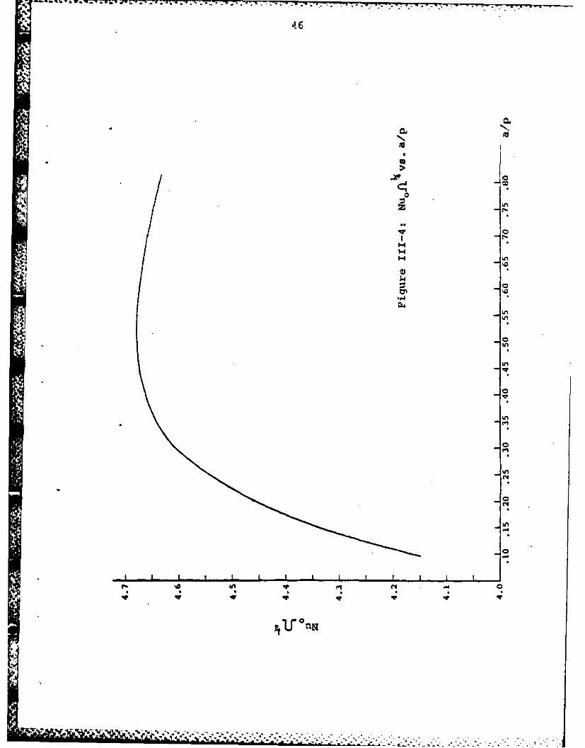
111-4 NUoRu /4 versus a/p .... ................ 46
111-5 Nu/Nu 0wversus w/wf................ 48
111-6 Nuo/Nu versus w/wf. ...... ............. 50
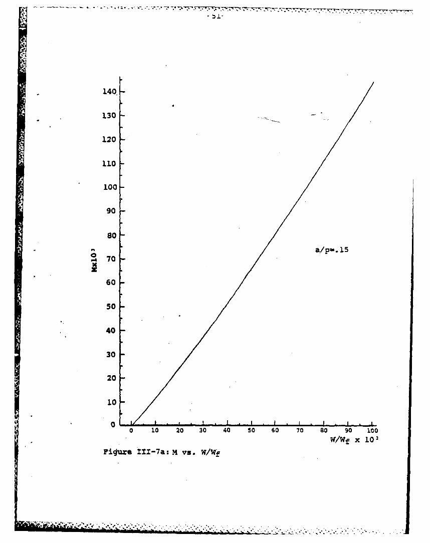
III-7a. M versus w/wf, a/p - .15 ... ........... 51
111-7b M versus w/wf, a/p 0 .35 ... ........ 52
111-8 Schematic diagram showing stripper platespacing and axial temperature distribution.. 56
IV-I A double-pass fluted condenser with sixdrainage segments. .................. .... 65
IV-2 A proposed method for rolling fluted tubesinto the tube sheet. ....... ....... 67
V-1 Nuz/Nu versus w/wf and M ............ 70
A-1 Schematic of a condenser tube. . ... ...... 81
A-2 Load reliveing factor,y, as a function offlute geometry.. .................... 86
i ..... "........ , . .-. -. . . . . . . . .... . . ... r :r, . " r : .. y ., ,,... ,, ,...., ....,. .. .... ...... ...... ..... .- .. ... ... .. .. . .. . .
Page 12
LIST OF TABLES Page
1-1 Thermal conductivity and yield strength ofseveral common metals and select alloys. *20
11-1 Mechanical properties and composition ofmarine condenser materials ... ........... 23
11-2 Galvanic series of metals in flowing seawater. - * * * * a . . o . . . .. . .... 28
11-3 Tube specifications for various designdepths . . . . . . . o . . . . . . o o o o 32
I1I-1 Sample calculations for condensate filmthickness. . . o . . . . . . . . . . . . . . o 43
111-2 Sample Calculations for Nu C114 =f(a/p) o 45
111-3 Calculated values for M and w/wf for severaldifferent values of a/p. o.. ... o. .... 53
111-4 Sample results for a fluted condenser. . . o 60
.111-5 values of Rox the resistance of theoxide film on the in-side and outsidesurfaces of clean tubes. .......... .o 63
V-1 Comparison between condensers using Cu-tNi
V-2 Comparison between a horizontal and a
fluted condenser.- o o o o o . . . . . 75
C-1. Solution for L, with (w/w f)1 - 0.060 .. . . . . 115
c-2 Solution for (w/wf) with L2 - 4.957 ft. o 117
C-3 Results for sizing the condenser asspecified as appendix C . . . . . . o o - 118
c-4 Comparison between equation (111-22) andcalculated results.- - o . . . . . . . o . . . 119
Page 13
-9-
CHAPTER I
INTRODUCTION
A. Background Information
In the design of a marine power plant, overall
thermal efficiency, weight, and volume are the driving
concerns (11. This is especially true for the steam
plant, which is the predominant form of propulsion for
large naval vessels. While a large marine diesel may
provide better specific fuel consumption than a fossil
fired steam plant, the latter retains several intrinsic
characteristics which make it attractive for naval pro-
pulsion. These advantages include:
1. Use of alternative heat sources.
In the case of a submarine, aircraft carrier,
or cruiser, a nuclear reactor provides the
thermal energy. In smaller ships, a boiler
is used as the steam generator.
2. Auxiliary steam generation.
Auxiliary steam provides water, hotel services,
and drives auxiliary equipment such as steam
catapul-ts on an aircraft carrier.
3. High speed.
The steam plant has a much wider operating
range than a large marine diesel. The design
of a naval steam plant usually provides for
..........-.... ;..o.................. ..............,-u u , ne mmm uum tld dl Rl~~d , . pL ,~ ' " a'. ._., , "",. ." .'- - . - - - . '-
Page 14
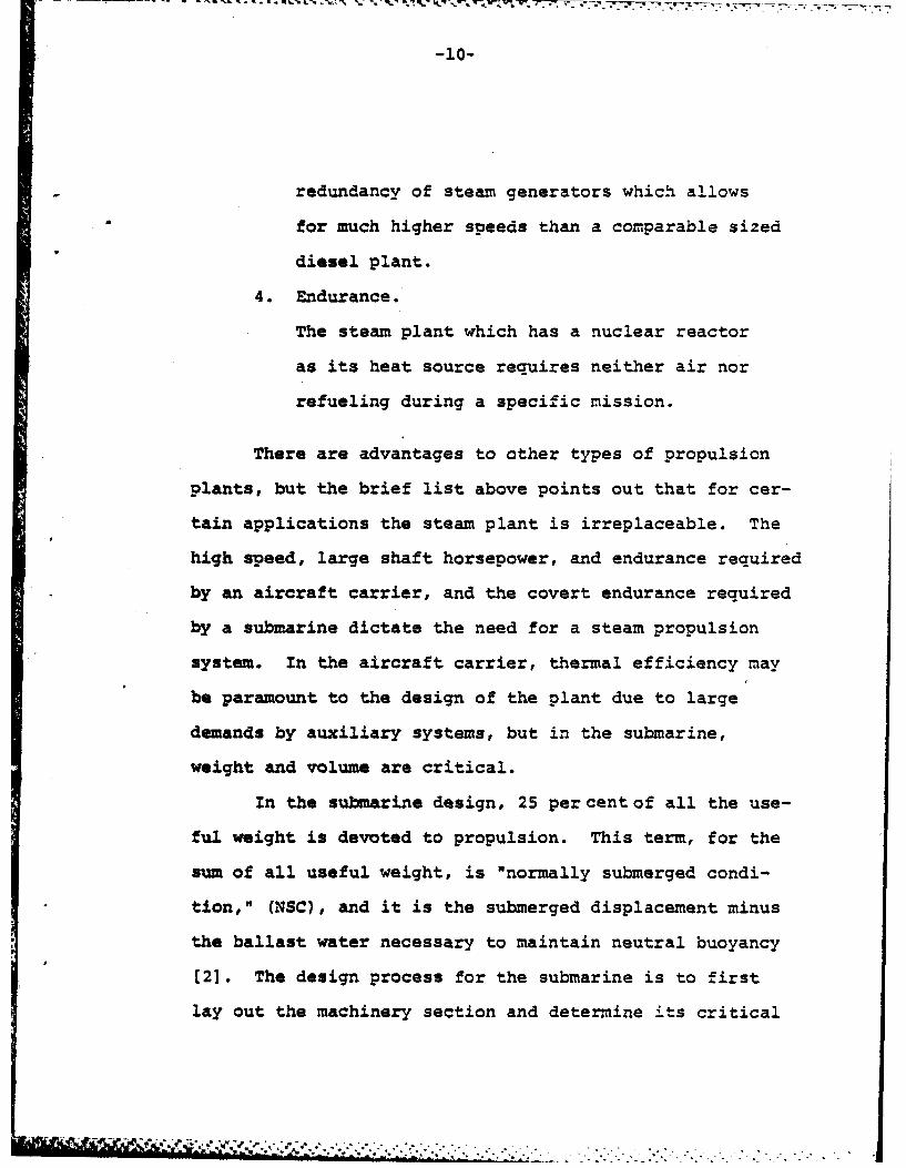
-10-
redundancy of steam generators which allows
for much higher speeds than a comparable sized
diesel plant.
4. Endurance.
The steam plant which has a nuclear reactor
as its heat source requires neither air nor
refueling during a specific mission.
There are advantages to other types of propulsion
plants, but the brief list above points out that for cer-
tain applications the steam plant is irreplaceable. The
high speed, large shaft horsepower, and endurance required
by an aircraft carrier, and the covert endurance required
by a submarine dictate the need for a steam propulsion
system. In the aircraft carrier, thermal efficiency may
be paramount to the design of the plant due to large
demands by auxiliary systems, but in the submarine,
weight and volume are critical.
In the submarine design, 25 percent of all the use-
ful weight is devoted to propulsion. This term, for the
sum of all useful weight, is "normally submerged condi-
tion," (NSC), and it is the submerged displacement minus
the ballast water necessary to maintain neutral buoyancy
[2]. The design process for the submarine is to first
lay out the machinery section and determine its critical
• , ,s u mmmm l(Jm~ll4 & " ,, ' wT m "-- """ .L....-....1.......... ..- . ._ .. . .
Page 15
length. This length is referred to as the "stack length."
Once the stack length has been established along with its
weight and volume, the remaining required weights are
added, and the overall buoyant envelope can be deter-
mined (3]. This envelope is the volume necessary for
neutral buoyancy. The stack length, therefore seriously
impacts on the total volume of the submarine, and the
" weight of the machinery also becomes a constraint. With
these two constraints merely removing weight from within
the buoyant envelope, may be insufficient to allow the
reduction of the envelope. Weight removal must often be
countered with addition of lead ballast. Conversely,
reducing the volume of the hull, but not the weight causes
negative buoyancy. Also, the decrease in volume of
specific items within the buoyant envelope allows greater
freedom in arrangement, but unless accompanied by a com-
mensurate weight reduction, a decrease in NSC will not
be realized.
Consider the fact that a Los Angeles class attack
submarine (SSN-688) costs 460 million FY-81 dollars [4].
This cost includes the cost of construction plus all
government furnished equipment. The dimensions of this
submarine are: length, 362 ft; diameter, 33 ft; and
submerged displacement, 6900 tons t 51. A very crude
,. . ., . .. . . . . .. . . .. . . .
Page 16
-12-
approximation would say that each foot of length costs
one million dollars and displaces 19 tons. So a moderate
reduction in the stack length which is accompanied by the
appropriate weight reduction should be worth several mil-
lion dollars in acquisition, with second order effects
being felt in horsepower requirements.
B. Objectives of this Work
The objective of this thesis is to develop a design
methodology for an alternative surface condenser than
those presently used in marine steam plants. This alter-
native condenser is expected to be smaller and lighter
than existing units, and it will have a higher overall
heat transfer coefficient.
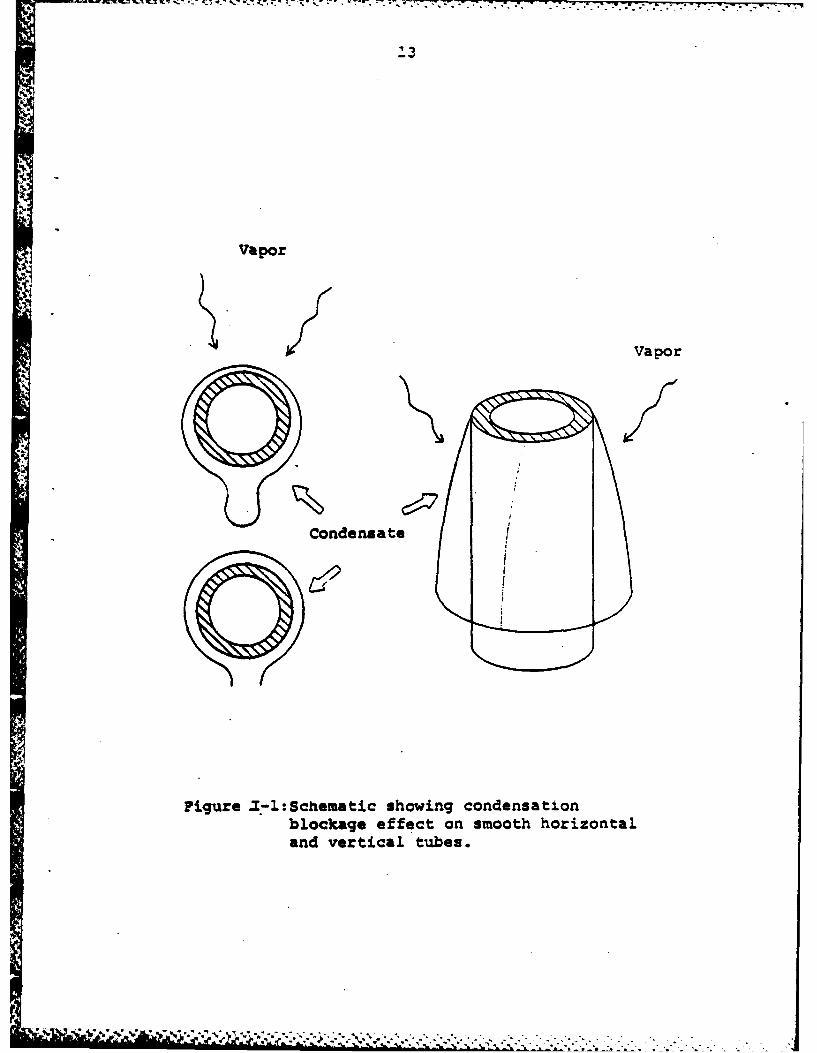
The average condensation heat transfer coefficient
on a smooth surface horizontal tube steam condenser is
approximately 2000 BTU/hr ft2*F. Condensation inundation
of tubes which are lower in the condensing tube bundle
significantly reduces their heat transfer effectiveness
(61. Vertical orientation of the smooth tube bundle
would not solve this inundation problem because a developing
boundary layer would cause similar adverse effects.
Figure I-I shows the blocking effect of the fluid for
horizontal and vertical tubes.
i ' .. ... -" " ""&'""." " " " " ." . ... ."" " " " *. *" "'" " +' '" " " ' ' " .. *. 1-. .
Page 17
K-717,r 7- 77 7, 7 -7 R7
Vapor
Vapor
Condensate
Figure Z.-1:Schematic showing condensationblockage effect on smooth horizontaland vertical tubes.
. *V.
Page 18
-14-
In 1954 Gregorig proposed condensing on vertically
oriented tubes with fluted axial surfaces (7]. Surface
tension of the condensate draws the liquid into the valleys
of the flute where it then drains down, leaving a thinner
liquid layer on the peaks. Figure 1-2 demonstrates this
concept. Heat transfer coefficients predicted for these
condensing surfaces using Gregorig's fluid properties and
temperature drops approach 8000 BTU/hr ft20F. In a pro-
cedure developed by Zener and Lavi (8] and refined by
Webb [9] for the design of an optimized Gregorig conden-
sing surface, heat transfer coefficients as high as
36000 BTU/hr ft2OF are reported by experiment and as high
as 55000 BTU/hr ft*'F are predicted. These surfaces,
however, may be difficult to manufacture, and for a
generally curved repeating surface of such small dimen-
sions as are required, the exact geometry may not be a
significant influence on the condensing heat transfer co-
efficient [10]. The extrusion capabilities of industry
are likely to set the limits on the geometry of the flute,
and for these reasons a quite regular geometry such as a
sine flute is considered. Longitudinal machining or axial
welding to achieve a specific surface geometry is not
acceptable for condenser tubes which are used in naval
vessels (111. By requiring seamless drawn tubes for
naval condensers, residual stresses and machining flaws
Page 19
-:4 --k- 7- 17 -0- P -m
Vapor
Figure 1-2: Fluted surface concept
Page 20
-16-
are avoided which could be sources of unexpected failure
when the vessel is subjected to extremes of pressure,
mechanical shock, or thermal shock.
The fluted surface having a sine geometry was
analyzed by Yamamoto and Ishibachi using the Gregorig
model [12]. Their analysis enables the calculation of an
average condensate film thickness on the surface of the
flute. The problem then reduces to one of balancing heat
transfer and condensate mass flow. The phenomenon of
the condensate filling the valley region of the flute is
referred to as "flooding," and this concern for flooding
presents the same problems as inundation of horizontal
or vertical smooth tubes. Panchal and Bell considered
the downstream effects of condensation as the valley of
the flute begins to fill [13].
Proposing an alternative condenser design which
simply re-orients the tubes and enhances their outer
surfaces should accomplish the goals of being smaller and
lighter. Condenser design considering alternative mate-
rials must be treated as part of the problem. Materials
which warrant consideration are Copper-Nickel (Cu-Ni)
90-10, Cu-Ni 70-30, and Titanium, commercially pure,
grade 2 (Ti, CP, Gr2). There are trade-offs for the use
of these materials, the most important of which are
strength and weight versus thermal conductivity.
, a ... ' ... .-.. . .•- - .
Page 21
i n . a o*d._.t t.. .. - - . . -. . -
-17-
In summary, the objective of this thesis is to pre-
sent a methodology for a marine condenser design which has
vertical fluted tubes and is possibly fabricated from dif-
ferent materials. This condenser must be lighter and
smaller than existing condensers to warrant its manufacutre
and installation.
C. Design Inputs
Constraints for a condenser design can vary widely.
For a marine condenser, these degrees of freedom are
somewhat narrower, and the design process is governed
by the concerns for weight, volume, and thermal efficiency.
For naval condensers, reference (111 further limits the
degrees of freedom in design. These limitations arise
because of the requirements for the naval vessel to be
able to operate effectively in varying environments.
The heat transfer requirements are for the conser-
vation of energy from the condensation side of the con-
denser, through the tube wall, and into the cooling water.
Thus the heat transfer characteristics can be analyzed
separately for these three different regions.
"VY"V, ] s $' , ,. ' . * ',,,. *f --' , .f.-t - .'. , '- .
Page 22
-18-
1. Cooling water.
Various correlations, such as McAdams, Colburn, or
Seider-Tate can be used to determine the heat transfer
coefficient for turbulently flowing cooling water [6].
Fundamental non-dimensional groups which determine the
cooling fluid heat transfer coefficient are the Reynolds
number and the Prandtl number. The design paprameters
which govern these numbers are temperature dependent fluid
properties, velocity, mass flow, and tube hydraulic
diameter.
2. Tube Wall.
Heat transfer resistance through the tube wall is
dependent upon tube material, wall thickness, and a scaling
allowance.
3. Condensing Fluid.
The heat transfer coefficient on the condensing
side of the tube will be shown to be a function of three
non-dimensional groups. These groups are specified by
surface geometry, condensing pressure (or temperature),
and condenstate drainage requirements [7, 12, 131.
Structural limitations are also defined in reference
11]. These are the source of considerable conflict with
the heat transfer requirements. The desireable high
, . . -, .. . . .
Page 23
-.19
strength materials generally possess lower thermal con-
ductivities and/or inferior metallurgical performance in
salt water than lower strength pure alloys. Table I-i
gives a brief comparison for several common copper,
nickel, and titanium based alloys. Stiffners are also
necessary to prevent excessive tube vibrations. These
stiffners may be used to provide condensate drainaae
strippers, but their spacing affects the condensation heat
transfer coefficient (13, 14].
Power available for cooling water is a constraint
which also affects the condenser design. Given a specific
pump/motor limitation, by either size or power available,
the velocity and mass flow of coolant are constrained.
Heat losses through the condenser are determined by
physical shape of the condenser, i.e., number of passes,
baffles, etc., tube length, and the Reynolds number. As
the tube length of the condenser decreases, a commensurate
amount of pumping power becomes available for either in-
creased coolant mass flow, or increased coolant velocity
(15].
An itemized listing of design parameters for a
marine condenser can be specified as follows [16]:
Page 24
.. .Ik, I- a- .7.
-20-
Table I-I
Thermal Conductivity and Yield Strength of
Several Common Metals and Select Alloys
[17,18]
Thermal Yield
Meal/Allo* Conductivity Stress**
[BTU/hr ft F] [ ksi]
Cu 230 v 4.8
Cu-NI 90-10 23 16
Cu-Ni 80-20 21 16
Cu-Ni 70-30 17 25
Ni (98.9% Pure)*** 47 16
onsl 400 (66.5 Ni-31.5 Cu) 14 45-25
Monel 500 (66.5 Ni-29.5 Cu- 10 i112.7AI-0.6Ti)
Ti (CP-Gr 2) 11.4-9.5 40
Ti-SAI-2.5Sn 4.5-4.3 120
Ti-6AI-4V 3.8 120
*Properties are for 50*F<T<I00F, annealed condition.
**Yield stress is defined for .2% deformation.
***Nickel and Ni-Cu alloys are unsuitable for marine tubingbecause they are subject to deep pitting in seawater atlow velocities [231.
.......- ..-.
Page 25
-21-
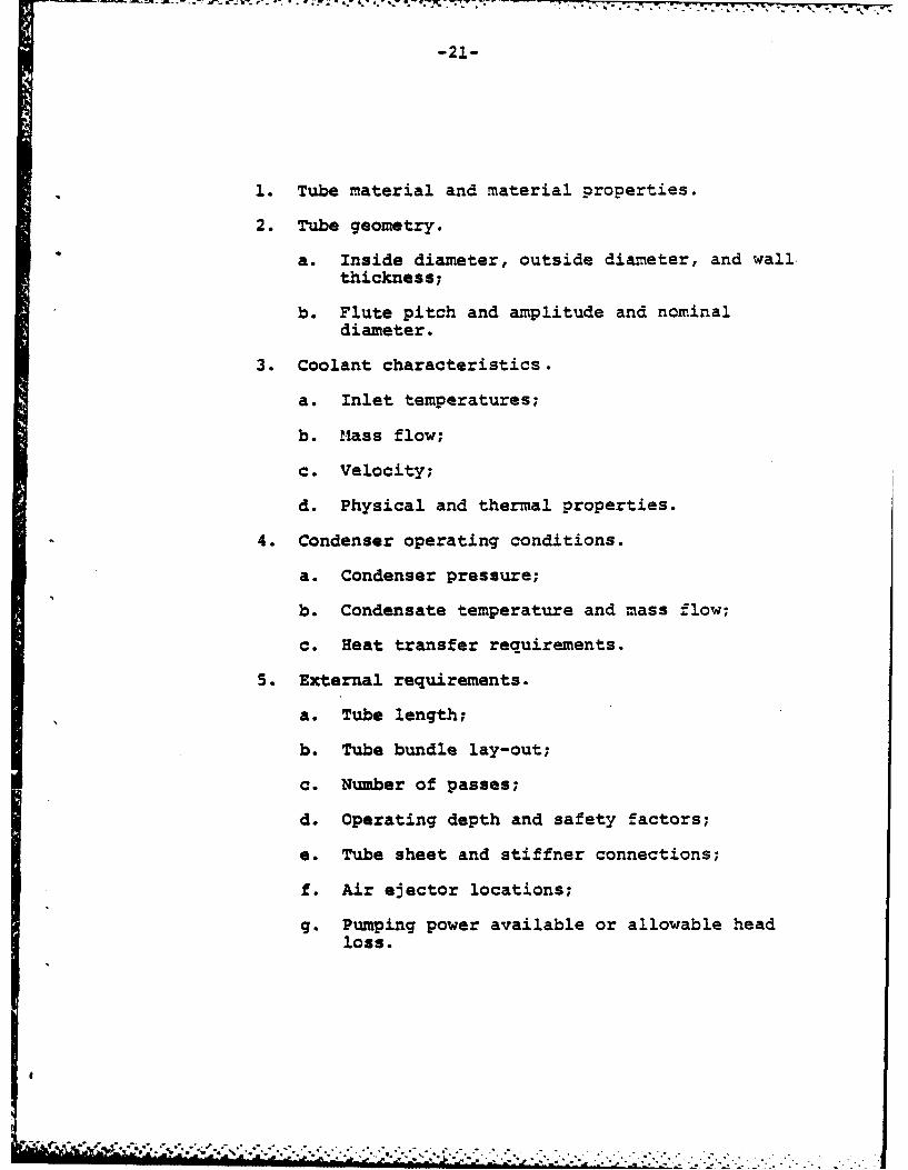
1. Tube material and material properties.
2. Tube geometry.
a. Inside diameter, outside diameter, and wallthickness;
b. Flute pitch and amplitude and nominaldiameter.
3. Coolant characteristics.
a. Inlet temperatures;
b. Mass flow;
c. Velocity;
d. Physical and thermal properties.
4. Condenser operating conditions.
a. Condenser pressure;
b. Condensate temperature and mass flow;
c. Heat transfer requirements.
5. External requirements.
a. Tube length;
b. Tube bundle lay-out;
c. Number of passes;
d. Operating depth and safety factors;
e. Tube sheet and stiffner connections;
f. Air ejector locations;
g. Pumping power available or allowable headloss.
4i
]
Page 26
-22-
CHAPTER II
TUBE SELECTION
A. Materials
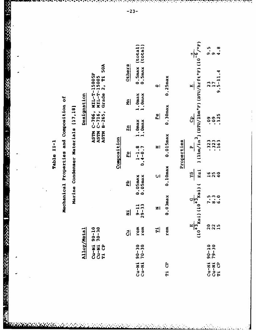
The materials which will be considered for marine
condenser tubing are the copper-nickel alloys, Cu-Ni 90-
10 and Cu-Ni 70-30, and commercially pure titanium, grade
2 (Ti, Cp). These materials are of interest because the
U.S. Navy uses both Cu-Ni alloys [11], and Ti is a possible
alternative material which will provide considerable
weight savings. Table 11-1 lists the mechanical and ther-
mal properties of these materials along with their compo-
sitions (17,181.
In selecting a material for use in a condenser,
several environmental factors must be considered. These
include corrosion characteristics and wear properties of
the material in a salt water environment, effects of bio-
logical fouling, and galvanic coupling.
1. Cooling water velocity effects.
The effects of sea water velocity on various metals
is summarized in Figure II-1.
a. Copper-Nickel Alloys.
Cooling water velocity is one of the more important
factors that affect Cu-Ni condenser tube deterioration.
,1v*, !-
Page 27
0 to %,
0 0
4) 4. 0
0c '04. .3(a4
o-~.4 P-4 n~
C 005 4 0) ** U E40 11 1 t (
0 0r A54
0 Go c (
_ u uz car -ox fa 24 (U
04 PC 2 02
1. a .,4 .Ooi 1o .
00 4J' 0aI2 14
54 0
.P+ 00 22
'~r- m2 00m
P-4 fn 00
.,41 1+ N N 4
#-4 0 -15
-r~*~'-~o-. U*t I*U E"--
A,~~~ .r -Sz u .-
Page 28
-24-
13I
.1 *\~. I.
16
00.
0 I 40
A A
a qq
Page 29
-25-
For these materials, a minimum velocity exists below which
stagnation occurs and crevice corrosion is likely. Above
a maximum critical velocity pitting and erosion occur.
For Cu-Ni 70-30 this lower velocity limit is approximately
2-3 ft/sec, allowing for crevices on the order of 1.0 mil
per year (mpy) [19,20,21]. Crevice corrosion character-
istics for Cu-Ni 90-10 are similar to Cu-Ni 70-30 (22].
Various values are reported for maximum critical veloci-
ties, above which impingement attack and erosion occur.
The maximum sea water velocity of 11 ft/sec, specified
by reference [11] is less than the generally accepted
critical velocity for the Cu-Ni alloys which is 12-15
ft/sec [20,221.
b. Titanium
Ti is very immune to the effects of velocity. This
behavior is attributed to a chemically stable, rapidly
formed, oxide film. Passivation occurs rapidly, even
in the presence of mechanical 4amage such as a scratch.
The oxide film "repairs itself" virtually instananeously
(21,22,231. In sea water at velocities between 0-3 ft/
sec, reported general corrosion rates are nil [21,23].
Crevice corrosion occurs with Ti only at temperatures
above 250*F (23], and no corrosion occurs at sea water
velocities up to 25 ft/sec and possibly greater [21).
I II " d' V~vW*K&. ..I.-*... - .l-i ~ ~ dm' , .*I.*. '- * , * , - : .j ,' -~ .,. ._. . ,..
Page 30
-26-
2. Biological Fouling
In general, the more corrosion resistant metals and
alloys are likely to experience biological fouling under
slow moving conditions. Fouling by macro-organisms
(mollusks, barnacles, etc.) has the obvious effect of
reducing water flow, changing velocity profiles, and in-
creasing pumping power requirements. Fouling by micro-
organisms (algae, etc.) has the effect of adding another
layer of thermal resistance to the inside of the tube
wall [24].
a. Copper-Nickel Alloys
Water velocities in excess of about 5 ft/sec,
temperatures above 120F and below 50*F, low oxygen con-
tent or low food supply (such as in stagnant or closed
systems) in the water will effectively prevent fouling
of copper alloys by macro-organisms [20]. The copper
alloys most resistant to all bio-foulding, however, are
those containing more than 85 percent copper. Thus, even
in a high velocity flow, some micro-biological fouling
(referred to as "slime") will occur on Cu-Ni 70-30 sur-
faces due to bacterial and algae growth and adherancewithin the boundary layer [20,25,26,27]. The irritant
or toxic effect of Cu 2+ ions is believed to be the cause
of reduced biological fouling on Cu-Ni alloy tubes (28].
4 . ,4 4 -
Page 31
-27-
b. Titanium
Since Ti is such an immune metal, biological fouling
is a serious problem. The threshold velocity to prevent
macro-biological fouling on Ti tubes is approximately 5
ft/sec [23,29]. Design of a system for active production
of toxic agents must ensure that these agents are not en-
vironmentally hazardous. A chlorination system is accept-
able to the environment, but the production of chlorine
ions (Cl-) is accompanied by hydrogen ions (H+). Hydrogen
ions are a hazard to titanium alloys, and except in the
case of very pure metal can cause stress corrosion
cracking [301.
3. Galvanic Coupling
When considering condenser materials, in the presence
of a strong flowing electrolyte, namely sea water, galvanic
effects are significant. The material itself, with its
propensity to passivate, and the velocity of the sea water
dictate the kinetics of corrosion due to galvanic coupling.
Titanium is a much more active metal than copper, but it
is because of this activity that it rapidly forms on oxide
and becomes passive. Hence it is more noble than copper,
and its general corrosion rates are much less. Table 11-2
shows the relative nobility of various metals in flowing
sea water, and it implies that Cu-Ni piping (used for
*
Page 32
-28-
Table 11-2
Galvanic Series of Metals in Flowing Sea Water [33]
Anodic or Least Noble
Magnesium and magnesium alloysZincGalvanized steelAluminumCadmiumMild steelWrought ironCast ironStainess steel 304 (active), 316 (active)LeadTinNaval brass (60% copper, 39% zinc, 1% tin)CopperRed brass (85% copper, 15% zinc)Copper-Nickel 90-10Copper-Nickel 70-30NickelINCONEL alloy 600 (78% nickel, 13.5% chromium,
6% iron)Nickel aluminum bronzeSilverTitaniumStainless steel 304 (passive)INCONEL alloy 625HASTELLOY alloy CMONEL alloy 400Stainless steel 316 (passive)INCOLOY alloy 825GraphitePlatinum
Cathodic or Most Noble
.--,..-x.. .. -.. -. ........ .. ...... . . . . . . . . . .
Page 33
-29-
most sea water piping) would deteriorate in the proximity
and in contact with Ti [23,31]. Reference £11] requires
zincs as cathodic protection in Cu-Ni tubed condensers
since Cu is noble relative to steel. The steel is ncble
relative to the zincs, and they therefore corrode sacri-
ficially. Such sacrificial anodes would definitely be
required in a Ti tubed condenser (321. In fact, the
deterioration rate for such anodes might dictate an
entire change in sea water piping systems to a more noble
metal which would then exacerbate the biological fouling
problem. Figure 11-2 demonstrates this concern for
cathodic protection requirements for a Ti tube condenser.
The significant variables for material use in
condenser tubing, apart from strength requirements, are
sea water velocity, galvanic effects, and susceptibility
to biological fouling. The latter two of these are also
functions of sea water velocity as shown in Figure I-1.
B. Strength Requirements
Reference [111 specifies for surface ship conden-
sers a minimum tube wall thickness of .049 in. with
Cu-Ni 90-10 alloy. The tube outside diameter is also
specified as 5/8 (.625) in. Appendix A shows the
Page 34
-30-
'V
,I: T, -4
r13 tir- B k 7
aiiitAS w tr ''rh i
Page 35
-31-
calculations required to determine condenser tube wall
thickness. These results are presented as Table 11-3.
The minimum wall thickness allowed in practice for Cu-Ni
70-30 is 0.049 in. and for Ti is 0.035 in. [34]. Thus, from
Table 11-3. replacing Cu-Ni 90-10 with Cu-Ni 70-30 Ti is
most practical strictly from a strength consideration for
a surface ship. Other considerations, such as increased
erosion protection in the face of a high velocity may
force the change in materials as shown in Figure I-1.
*The question of tube wall thickness for a sub-
marine condenser is complicated by security requirements.
These can be treated academically by the following con-
servative assumptions:
1. The design depth of a submarine is not the
depth at which it operates. A safety factor
has been applied which may be either additive
or multiplicative.
2. The yield criterion for tube wall material also
incorporates a factor of safety.
Appendix A shows the calculations required to pro-
duce Table 11-3. Table 11-3 presents various condenser
tubes required for different design depths.
i " " > ' ,S .. .. . ..
Page 36
- - . ..• . * - o .7
-32-
Table 11-3
Tube Specifications for Various Design Depths*
Design Depth (ft) Material OD(in) t(in) Gauce
1050 Cu-Ni 90-10 .625 .049 181050 Cu-Ni 70-30 .625 .028 221050 Ti CP .625 .019 --
1500 Cu-Ni 90-10 .625 .083 141500 Cu-Ni 70-30 .625 .049 181500 Ti CP .625 .028 22
2000 Cu-Ni 90-10 .625 .109 122000 Cu-Ni 70-30 .625 .065 162000 Ti CP .625 .035 20
2500 Cu-Ni 70-30 .625 .083 142500 Ti CP .625 .047 18
3000 Cu-Ni 70-30 .625 .095 13+
3000 Ti CP .625 .058 17+
1050 Cu-Ni 90-10 .500 .035 201050 Cu-Ni 70-30 .500 .028 221050 Ti CP .500 -- --
1500 Cu-Ni 90-10 .500 .065 161500 Cu-Ni 70-30 .500 .035 201500 Ti CP .500 .022 --
2000 Cu-Ni 90-10 .500 .083 142000 Cu-Ni 70-30 .500 .049 182000 Ti CP .500 .028 22
2500 Cu-Ni 70-30 .500 .065 162500 Ti CP .500 .035 203000 Cu-Ni 70-30 .500 .083 14
3000 Ti CP .500 .049 18
Thickness for tubes has been rounded to the nearesteven gauqe except as noted by 4.
t' ..'.... "- .. ". .. ....... .. .... . ... .
Page 37
-33-
CHAPTER III
ELEMENTS OF HEAT TRANSFER
Nomenclature
a amplitude of the flute (ft)
A area (ft2 )
B dimensional group defined in eq. (111-7)
(ft/OF)
C, Cp specific heat. (BTU/lbm°F)
D diameter (ft)
F number of flutes on the tube surface
9c gravitational constant (Ibm ft/lbf hr )
G mass flux (ibm/ft2 hr)
h heat transfer coefficient (BTU/hr ft 2 OF)
hfg latent heat (BTU/lbm)
K thermal conductivity (BTU/hr ft*F)
L length (ft)
M non-dimensional group defined in eq. (111-16)
Nu Nusselt number
p pitch of the flute (ft)
P pressure (lfb/ft 2 ) or (in-hg-abs)
Pr Prandtl number
q heat flow (BTU/hr)
r radius of curvature of the fluted surface
(ft)
-1. - -. .-- 1
Page 38
i "- - - -- T- T -I .. . . . . . . . . . . . . . . . .
-34-
R thermal resistance (hr ft 2F/BTU)
Re Reynolds number
Sv flute half perimeter (ft)
Sc flute arc length on which condensing occurs
(ft)
t tube wall thickness (ft)
T temperature (F)
T- Tw (OF)
U overall heat transfer coefficient (BTU/
hr ft2 0F)
V velocity (ft/hr)
W axial mass flow of liquid (Ibm/hr)
y tube surface coordinates
z
Greek letters
height of the condensate in the center of
the flute (ft)
r mass flow rate in S direction per unit
length (Ibm/hr ft)
6 condensate film thickness (ft)
e angular representation of a point along
the flute surface
/ I II : :l - q " *. ''. - - .. ... . .- .
Page 39
-35-
dynamic viscosity (ibm/hr ft)
density (ibm/ft3)
a surface tension (lbf/ft)
* non-dimensional group defined in eq. (B-12)
non-dimensional group defined in eq. (111-7)
Subscripts
b at bulk temperature
c coolant
D referenced to hydraulic diameter
f at flooding conditions
i inside
n nominal
o outside
s saturation
w wall
sc scale
Symbols
average
Page 40
-36-
A. Heat Transfer Coefficient of Cooling Water
No simple analytical solution exists for heat trans-
fer in turbulent pipe flow. The McAdams correlation (or
Dittus-Boelter equation) is widely accepted for the
determination of the heat transfer coefficient for the
cooling water [6,391.
= 0.023 -P, 0 F (11'-1)b b
or
Nu.D - 0. 023 (Re,,]0 8(Pr) n (111-1a)
where
1) n - 0.3 if the fluid is being cooled
- 0.4 if the fluid is being heated
2) all fluid properties are evaluated at the
average (or bulk) fluid temperature7
3) 2300 < ReD < 10 where
ReD =_ Reynolds number based upon the
hydraulic diameter
4) 0.5 < Prb < 120 where
Prb Prandtl number based on bulk temperature
5) L/D > 50
, ,,, --.. .. . . . . . . . . . . . . . . . . . . ", "- - . . . - -" ." . ,-.- .- -,- . .- ,
Page 41
-37-
For flow through a condenser tube, these conditions
are usually met and equation (111-1) is used as a basic
relationship.
B. Heat Transfer Coefficient for a Tube Wall
For materials such as pure copper which have
extremely high values for thermal conductivity, the
thermal resistance of the condenser tube wall is almcst
negligible. From Table 1-1, it is apparent that the
strength requirements for marine condenser tubes mandate
the use of materials with relatively low thermal con-
ductivities.
The thermal resistance of the tube wall is the
reciprocal of the heat transfer coefficient of the wall.
For a smooth (non-enhanced) tube, this may be written as:
Zn (Do/D i )Dre
1 0 /) ref (111-2)h 2
For a fluted tube, however, the nominal diameter is used
in place of the outside diameter [40]. The nominal
diameter is defined as:
Dn = D + 2a (111-3)
n m mun m m il milllIl i ilm nlm' T..ulm[ '- . , -1 . . ... . _
Page 42
-38-
This is shown in Figure III-i. Use of the nominal dia-
meter will be shown to be reasonable for two reasons:
1. The size of the flute is small with respect
to wall thickness. (This is exaggerated in
Figure III-l).
2. Heat transfer is blocked by condensate at the
bottom of the flute valley as shown in Figure
111-2. [9].
Furthermore, it is convenient to work with the nominal
diameter vice the outside perimeter when dealing with
the heat flux and condensing heat transfer coefficient.
Equation (111-2) can be written as:
h w 1 (III-2a)
Ln (Dn/Di) Dn
K 2
C. Heat Transfer Coefficient for Condensation
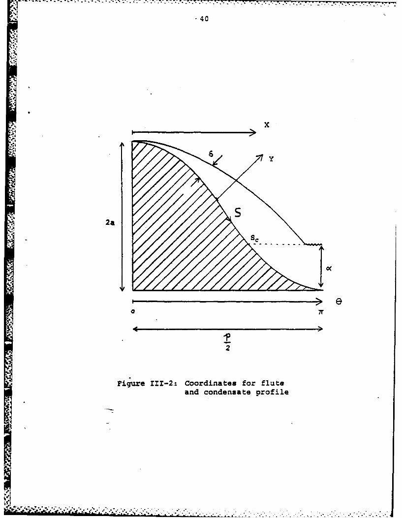
The coordinate system for this analysis is schemati-
cally depicted in Figure 111-2. The arc length, S, is
calculated by
S = ( 6L +f(-rI sin 211 db (111-3)
0
, ":-,' ,,,-'..'.;.,;.',,v-......-.-.---,... . ..-........ .... . .. .. . . .. -
Page 43
- q- r~rr. . - . .
-39-
-.4
4;
I -J
S.S.,
i I'-~ I /1 -.
-9 I -~
0
-4 ~I C-'.-.
j I ioA* 2 I
1 4-'
* I I Sis,
I .1')
I I
2)
Li..
*~'~ ~ ****.*~'*~ * ~.2 - . . . - -- -
Page 44
'40
x
2a
0 7r
2
Figure 111-2.: Coordinates for fluteand condensate profile
It ! A4
Page 45
-41-
The radius of curvature of the fluted surface which has
a sine geometry is
a1 + [L212 2 13/2
2 (111-4)acase
From Figure 111-3 it can be shown that
dP = fZ)(111-5)
Appendix B shows that the equation for the condensate
film thickness, 6, for a curved surface with a surface
tension induced pressure differential is
- d. (d11-6)
Ta3a N Ts-rj
where a is defined as
uKAT BAT (111-7)ahfggca a
The steps for solving equation (111-6) are shown by
Gregorig [7] and Yamamoto and Ishibachi [12]. The solu-
tion is presented in Appendix B. Sample calculations
are shown in Table 111-1.
... 4 oB~ - t . .q~o~ *. . . .. o..... . ..- . . -... -._ ;,,.",.... ,, .:. ..'.'. ..',',.. . ., ... . .. , ., .... .... . 5 .-. -', .. .. . . " .. . . . . . ,
Page 46
-42-
VV
i Fr: 0 -t6 6 Sine/) x a
~F. s0 6 cosG/9 - 6 coc5 e/,2
Figurc. !fl. Sc. mv3+.Ic of % i 5"r~ace
and swrface- tes~n
Page 47
-43-
Table III-i
Sample Calculations for Condensate Film Thickness
a/p .15 .35 .45 .55n
in Xl0 5 ft
0 1.5811 .4878 .3262 .2422
5 1.7219 .6673 .5436 .4802
10 2.0708 1.1451 1.0717 1.0522
15 2.5861 1.8466 1.8404 1.8785
20 3.1842 2.6712 2.7420 2.8451
25 3.7202 3.4183 3.5596 3.7215
30 4.0099 3.7606 3.9258 4.108335 3.9580 3.5078 3.6242 3.7693
40 3.6563 2.8574 2.8858 2.9616
45 3.2976 2.1107 2.0450 2.0468
50 3.0909 1.4664 1.3067 1.2374
55 3.4029 1.1087 .8361 .6900
60 6.7751 1.8444 1.2311 .8894
a - 2.00 x 10- 3 ft
- 3.7649 x 10 - 9
a@ - 1/60
n f(nae)
r.
p'' ;; ," ' : ', ,--; . .- . .. . . + .. . .
Page 48
'W_.......... -;
-44-
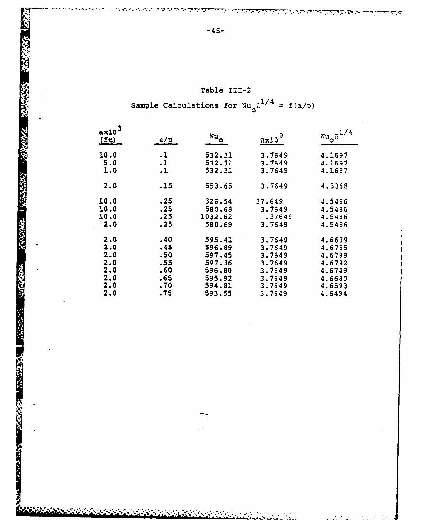
From the results of equation (111-6), solved for
the arc length Sc = S v , Nu0 can be calculated as shown
in Appendix B. A non-dimensional number, Nu o.I 4, can
be calculated, and from equation (111-6) and the defini-
tion of Nu.,
NU0a14= f(a/p)(1-)
This result is presented in Table 111-2 and plotted in
Figure 111-4.
At a distance Z down the tube, condensate W runs
down the flute, and the thickness of this condensate, a
(Figure 111-2), increases with Z. Here the heat transfer
is neglected in the valley of liquid thickness a, and the
integration of equation (111-6) stops at S = Sc. Sc is
determined by equation (111-3) and e
ec - ] (111-9)
When a - 2a the valley is flooded [13], and W = Wf
where
Wf - 2g -2 (2a)4 6 exp {3.33 - (111-10)f ' .".
Page 49
-45-
Table 111-2
Sample Calculations for Nu n/4 = f(a/p)axl00
&X10 Nu 9Nu 11/4(ft)- a/ 0u._.~ Qxl09 0
10.0 .1 532.31 3.7649 4.16975.o .1 532.31 3.7649 4.16971.0 .1 532.31 3.7649 4.1697
2.0 .15 553.65 3.7649 4.3368
10.0 .25 326.54 37.649 4.548610.0 .25 580.68 3.7649 4.548610.0 .25 1032.62 .37649 4.54862.0 .25 580.69 3.7649 4.5486
2.0 .40 595.41 3.7649 4.66392.0 .45 596.89 3.7649 4.67552.0 .50 597.45 3.7649 4.67992.0 .55 597.36 3.7649 4.67922.0 .60 596.80 3.7649 4.67492.0 .65 595.92 3.7649 4.66802.0 .70 594.81 3.7649 4.65932.0 .75 593.55 3.7649 4.6494
I- AU
Page 50
* f l U ~ k ' ~ j r . . ~ ~ ' ~ k " ~ . " a " - * . s . U - U-.
tn
0 n0
Page 51
-47-
or
Wf - g - p exp 3.33 (III.10a)
A Reynolds number is defined [13] as
Re - 4W (WI.1)SvLM V9
Calculations by Panchal and Bell (131 show
WZ Re ( z M) 3 "25 2
W Re PA25 (111.12)Wf Rf a
From Appendix B and equations (111-9) and (111-12)
hz=Nu3 z fRe 1al f - i w al1o ~ Ref' P ~ f (III.13)
This is shown by example in Figure 111-5.
An energy balance on the tube surface requires
.rDhzdZ m Dn AT - hfg dW p-- (111.14)
This equation is re-arranged and integrated between Z =0
and Z - L.
*q*d. . .. . .- 2
Page 52
* ** * -. * . .7~1
U
a - a~.. *~,* . - n * . *.. *. . * * . - * . . -
Page 53
.*48
I /I- y
//
.I
/I!,
I'I-I
- 0Or .
I' U"I = = =",ld '':::' '- """ ''-::"- - .- - . . ' ;, " ' - a " " "-
Page 54
hZpji K u WLL p AT . p =oi Nu° dW
h W NUz (BAT1/4 Wfzfg f U BAT 0 u
By grouping the constants in the right-hand expression,
M can be defined as
Ka14IN N 0 Q1/4 1 fLAT3/4 1 (W/W f)L Nu rhf (B)1/4 Wf 0 NU dWffg 0 u f
(111.16)
Figure III-S is replotted as
= f (111. 17)Nuz W
and presented as Figure 111.6. The integral in
equation (111.16) is evaluated from Figure 111-6, and
two of the cases are presented in Figures III-7a and
III-7b. These results are also tabulated and presented
as Table 111-3. Note that the integration smooths out
most of the dependency on (a/p) so that
' * - --
Page 55
.,'-,, - C
' i
%'
S.\ \
-I i n Sfm• - • •\. 1° l 4
a) * e
•.
Page 56
i , • ° .° . . o .. . °-. - .r
.40.
130
120
1.10
100
90
80
a/p=. 1.5
~70
60
50
40
30
20
10
0 10 20 30 40 50 60 70 80 90 100
w/wf x l0o3
Figure 1I-7a: M vs. W/Wf
- , .. . . ft. ,,. .f .; . ... . '. . . 'f ' - '_t " , - , . , , , .
Page 57
-52,
140-
130-
120-
100
90-
- a/p -. 35S70-
60-
50-
40
30-
20-
10-
00 L0 20 30 40 SO 610 70 80 90 1.00
W/Wf X 10O3
Fiqu~e 111-7b.- m vs. w/Wf
-w -~ ~ * *51
Page 58
~-53-
Table 111-3Calculated Values for M and IT
ffor Several Different Values of a/p
M x 10 3
II3wx 10 a/p - .15 a/p =.5a/p .55Wf
0 0 0 0
1 1.06 1.07 1.07
2 2.18 2.21 2.24
3 3.35 3.38 3.42
4 4.44 4.56 4.62
5 5.61 5.77 5.85
6 6.79 6.97 7.08
7 7.98 8.22 8.32
8 9.19 9.46 9.58
9 10.40 10.72 10.85
10 11.63 11.98 12.12
15 17.87 18.43 18.62
20 24.36 25.04 25.26
30 37.61 37.75 38.97
40 51.48 52.56 52.76
50 65.97 67.14 67.20
60 80.75 81.95 81.88
70 96.07 97.15 96.90
80 111.63 112.55 112.08
90 127.67 128.30 127.55
100 143.96 144.21 143.16110 160.70 160.46 159.05
/ I / - -. V I - . . - .i . " . " -' "" - -" " -'' . "" -' ' ' " " " . . . . '' . ' . ,"-'
Page 59
-44
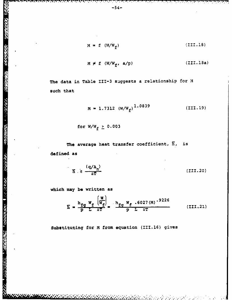
M f (W/Wf) (111.18)
M M f (W/Wf, a/p) (III.13a)
*} The data in Table 111-3 suggests a relationship for M
such that
M = 1.7312 (W/Wf) 1.0839 (111.19)
for W/Wf > 0.003
The average heat transfer coefficient, S, is
defined as
(q/An)- T (111.20)AT
which may be written as
hf h Wf .6027(M) 9 2 2 6
p L AT p L AT
Substituting for M from equation (111.16) gives
Page 60
-55-
.0774 -. 9226 -3 ' .2307
hfWf .04 (a/9) K-. 60271 LAT a .2307 p" K Pch g
(111.22)
where f(a/p) - Nu 0 1/ 4 from Figure 111-4. At L = 0
this should show that h - F . The relationship for w/wf
and M fails, for w/wf < 0.003, and this equation for
goes to -.
D. Application to Condenser Design
In the design of a fluted condenser, it may be
desireable to place stripper plates along the length to
remove the condensate well before it reaches the flooding
flow rate - perhaps keeping w/wf 1 0.1. Figure 111-8
shows such stripper plates.
To determine L and w/wf, a system of 4 equations
must be solved. Other unknowns to this system of equa-
tions are: (q/An), Tc2 and AT. Therefore, one of these
five variables must be specified. In practice, either
L or w/wf would generally be chosen. The system of
equations is:
Ja F
Page 61
-56-
wc T"vii- -7_."e . . . . .
-ZZC
2 L -
F; u rZL e X- - 5 c li e- -tati a
.Strippe~r plat L s pa ci 13 a nd axI al
te wnPerat iAre di~tri t 'on.
Page 62
- -.-. . . .-. - . -- - . -
-57-
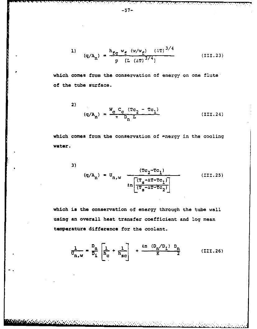
h) (. (W -T) 3/4
(q/An) hfg w (w/wf) 1.3p (L (,iT) (23
which comes from the conservation of energy on one flute
of the tube surface.
2)
(q/An) Wc Cc (Tc2 - Tci) (111.24)Ir Dn L
which comes from the conservation of -nergy in the cooling
water.
3)
(q/A) = Un,w - (Tc 2-Tc1 ) (111.25)
in (T.AT-Tc 0('~T.AT-Tc 2)A
which is the conservation of energy through the tube wall
using an overall heat transfer coefficient and log mean
temperature difference for the coolant.
D n [1 1 Zn (Dn/Di) D (n
W_ Uw + 2(11126)Un, w ci + s c]2
144
Page 63
,.i -5 8-
For short lengths or small temperature rises in the cool-
ant, the log mean temperature difference may be replaced
by
(Tc2 - Tc1 )T T Ts AT Tc (111.27)
in T a-AT-Tc1I(n[Ts-6T-Tc2 Iq
where (TC + Tc(I.28)1c (T 1 T 2)
The fourth equation of the system comes from the defini-
tion of M in equation (111.16)
(AT) 3/M wf (B)1 4 hf (111.29)ELAT)3"4] (Nu 0 1/4) (a) K
where M is approximated by equation (111.19).
With L specified and w/wf allowed to float, the
solution to these equations is as follows:
1) Assume Tc2
2) Assume AT
3) Solve for (q/An) in equation (111.25)
4) Solve for (w/wf) in equation (111.23)
5) Solve for M in equation (111.19)
. . . -..
Page 64
-59-
6) Solve for "T in equation (111.29)
7) Repeat steps 3-6 until
1AT i - ATi+1 1 e_ IT
8) Solve for Tc2 in equation (111.24)
9) Repeat steps 2-8 until
ITc 2 j - Tc 2 j+ll _ I-Tc 2
With w/wf specified and L allowed to float, the
solution to these equations is as follows:
1) Assume Tc2
2) Assume L
3) Solve for AT in equation (111.29)
4) Solve for (q/An) in equation (111.25)
5) Solve for L in equation (111.23)
6) Repeat steps 3-5 until
ILi - Li+i1I I eL
7) Solve for Tc2 in equation (111.24)
8) Repeat steps 2-7 until
ITc2j - Tc 2 j+il! ITc 2 -
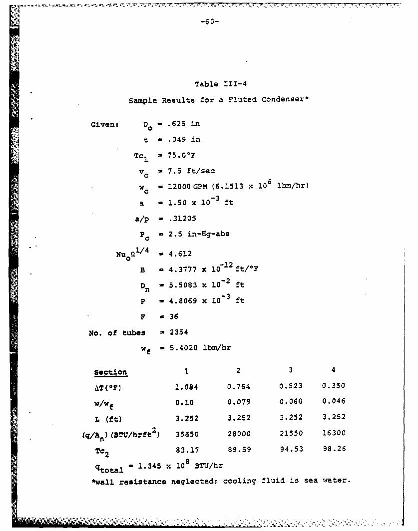
Table 111-4 shows the results of these calculations
for a typical condenser, neglecting thermal resistance
in the wall. Appendix C shows the calculations for the
solution to this system of equations as applied to a
condenser design.
Page 65
-6 0 -
Table 111-4
Sample Results for a Fluted Condenser*
Given: D- .625 in
t - .049 in
Tc I = 75.0*F
v c = 7.5 ft/sec
wc = 12000GPM (6.1513 x i0 6 bm/hr)
a - 1.50 x 103 ft
a/p - .31205
Pc = 2.5 in-Hg-abs
Nuon 1/ 4 a 4.612
B - 4.3777 x 10 1 2 ft/°F
Dn - 5.5083 x 10- 2 ft
P - 4.8069 x 10 ft
F - 36
No. of tubes - 2354
wf - 5.4020 ibm/hr
Section 1 2 3 4
4T(OF) 1.084 0.764 0.523 0.350
w/Wf 0.10 0.079 0.060 0.046
L (ft) 3.252 3.252 3.252 3.252
(q/An) (BTU/hrft ) 35650 23000 21550 16300
Tc2 83.17 89.59 94.53 98.26
qtotal , 1.345 x 10⁸BTU/hr
*wall resistance neglected; cooling fluid is sea water.
+ ' ¥+' +~~. . . . .. . . . . . . . . . . . . . . . . . . . . . . . . . .. . . .. _, -- -,. - , -, , - m
Page 66
-61-
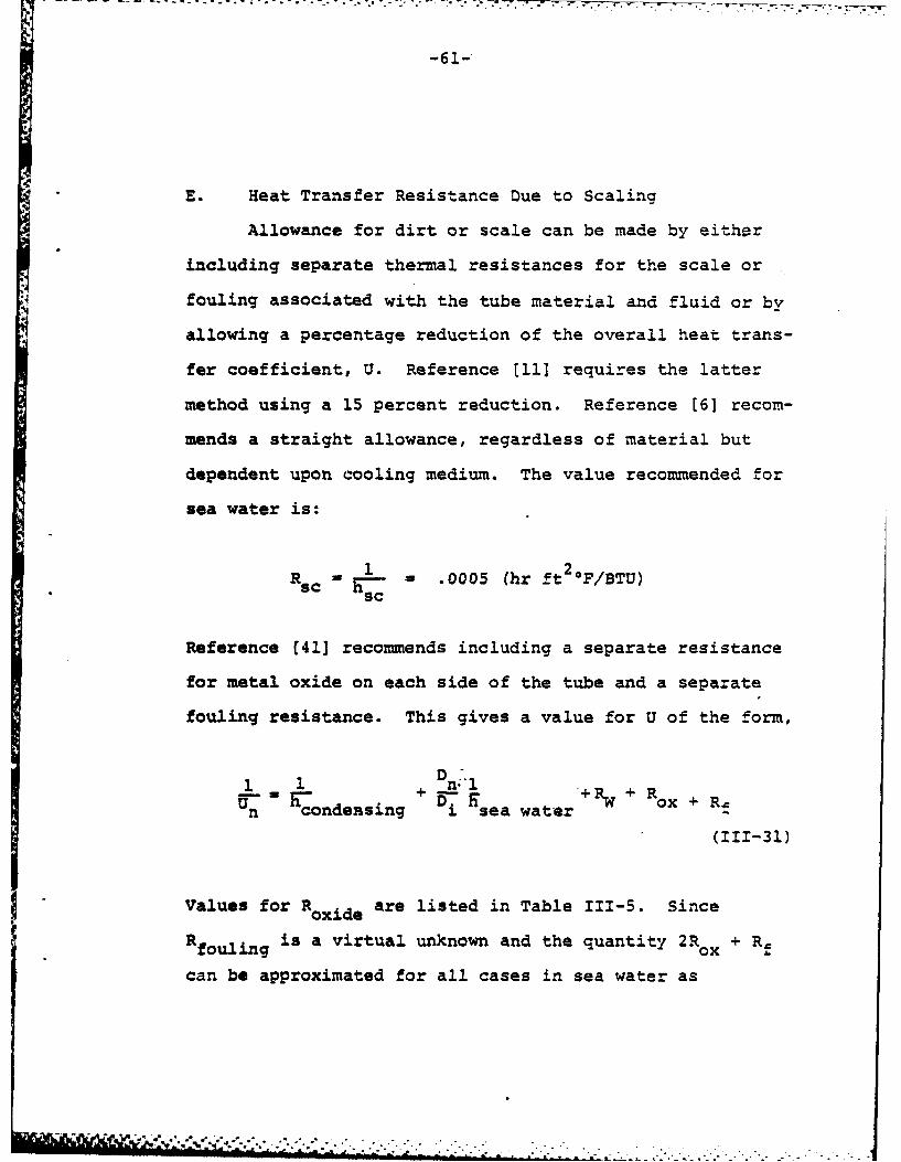
E. Heat Transfer Resistance Due to Scaling
Allowance for dirt or scale can be made by either
including separate thermal resistances for the scale or
fouling associated with the tube material and fluid or by
allowing a percentage reduction of the overall heat trans-
fer coefficient, U. Reference [11] requires the latter
method using a 15 percent reduction. Reference [6] recom-
mends a straight allowance, regardless of material but
dependent upon cooling medium. The value recommended for
sea water is:
-Sc W = .0005 (hr ft 2 °F/BTU)Rsc= sc
Reference [411 recommends including a separate resistance
for metal oxide on each side of the tube and a separate
fouling resistance. This gives a value for U of the form,
+ TRWo+ R xU- -_ h 0n~ ++.n condensing i sea water x +
(111-31)
Values for Roxide are listed in Table 111-5. Since
Rf is a virtual unknown and the quantity 2R + R
can be approximated for all cases in sea water as
Page 67
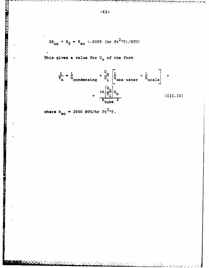
-62-
*2R ox + R f cm.0005 (hr ft 2 .F)/BTU)
* This gives a value for U.of the form
1n w 3cnesn [sea wae scalej
%hc~ndenn D I wae
+ Dfi (111.32)
Ktub~e
where h -c 2000 BTU/hr ft 2 0.
Page 68
-63-
TABLE 111-5
Values of R ox the Resistance of the
oxide Film on the Inside and Outside
2! Surfaces of Clean Tubes (41]
Tube Material ode{rtl
Admiralty Metal 0.000136
Aluminum Bronze 0.000153
Aluminum Brass 0.000167
*Cu-Ni 90-10 0.000178
Cu-Ni 80-20 0.000193
Cu-Ni 70-30 0.000243
Titanium 0.000195
Page 69
-64-
CHAPTER IV
DESIGN PROPOSALS
A. Condenser Geometry
A primary objective of this work is to provide a
methodology for a condenser design which allows the naval
architect to specify condenser length. The naval archi-
tect is constrained by weight and volume, but the dimen-
sion which is most critical in marine plant layout is the
tube length. The transverse area of the tube bundle can
grow with significantly less impact on the other en-
gineering systems than axial growth. By specifying the
tube length, the maximum tube deflections and vibration
characteristics can be predetermined. This allows the
placement of tube and shell stiffners which may also act
as condensate stripper plates as suggested in Figure
111-8. For typical spacing requirements of 1-8 feet,
flutes with amplitude of 12-24 mils (1.0 - 2.0 x 10⁻³ ft)
are predicted by this work. Appendix C demonstrates how
a length may be specified for a condenser design. A
typical double-pass fluted condenser drawing is shown
in Figure IV-l.
Page 70
-- I
Coo1ing ater .LColngwaes. uppy I'! : n £
Steam inlet
Steam impingementbaffle (2)
Flut ad tubes
(noed shown) _--Downcomers (Typical)
Floating head
Condensate
)o4 FiqUre-*IV-L: Possible configuration fora 2 Pass Vertical Condenser
' "..
Page 71
-66-
B. Tube Attachment
A serious consideration for a naval condenser is
the ability to pull and replace or plug tubes without
having to remove the entire condenser or tube sheet.
Tubes in naval condensers are usually attached to the
tube sheets by rolling their ends and actually pressing
them into the tube sheet (41,42]. This procedure is
well established for Cu-Ni alloys, and rolled Ti tube-
to-tube sheet joining procedures are being established
t o meet naval heat exchanger requirements [43].
Figure IV-2 is a drawing of a proposal to facili-
tate fluted tube attachment to the tube sheet while
maintaining the ability to pull a tube if required.
As shown in Figure IV-2, a forged collar can be placed
around the fluted surface at points where attachment is
desired. This collar could be snugged into place by
heating it, prior to attachment, and allowing it to cool
around the tube. Reference [41] shows a similar attach-
ment for ferrules to allow longitudinal expansion.
Reference [42] reports successful rolling of 5/8 inch
diameter Ti tubes with 0.049 inch wall thickness. The
*composite wall thickness for a Ti tube with flute ampli-
tude of 18 mils and tube wall thickness of 0.035 inches
is 0.710 inches. This may pose a problem, and further
research is warranted.
Page 72
F,~~~- 'j ..- 4 ~
-67-
F'igure IV-2 -A ?rposed :.!ethiod ffr ?.ofling F'iutad Tubes into
the Tube Sheet Showing a Shaped Band Arounid tche Tube.
Page 73
CHAPTER V
RESULTS AND CONCLUSIONS
A. Comparison with Nusselt analysis
The average heat transfer coefficient for conden-
sation on a fluted surface is given by equation (111.22).
FKa hfg-I 2307 (ag )* 2307
h fl .6027L 1.A jp
x a 2037 [f(a/p" 9226 F f wf7.774
L LLT
(111.22)
From the Nusselt analysis for condensation on a
smooth vertical surface,
253 .25
h u-.943 L (V.1)
These two equations show a much different dependence
on the axial length L, but hfl is strongly influenced by
pitch. AT also affects F fl more than hNu. All other
things being of a similar magnitude or extremely weak
functions, H fl is dominated by p, AT, and a. The Nusselt
analysis shows that hNu is strongly affected by L and AT.
Page 74
-69-
Figure V-I is a graph relating the average heat
transfer coefficient with length. Since M as defined in
equation (111.16) is linear with L, the relationship
between (w/wf), M, and L for a given EL (or hL/ho -
NuL/Nuo) can be seen to be unique.
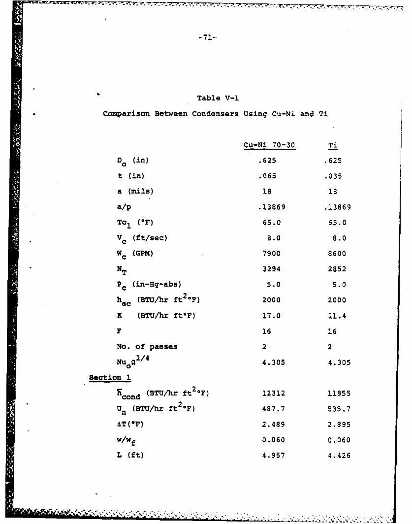
B. Conden' 'r Comparison Using Titanium
To cc..,.are a Ti condenser with the Cu-Ni 70-30
condenser cited in Appendix C, another constraint must
be included. Since the Ti tubes have thinner walls,
less of them will be required for the sea water mass
flow. This implies that the Ti condenser will either
be longer or transfer less heat. An alternative is to
allow the mass flow of the coolant to increase, i.e.,
increase the number of tubes. This will be the approach
taken here so that the condenser length and overall heat
transfer remain the same. Table V-1 shows the differences
between these two condensers.
No attempt has been made in Table V-1 to assess
the overall weight change between Cu-Ni 70-30 and Ti as
condenser materials for the example condenser. This
overall weight change must include tube sheets, structural
elements, waterbox heads, affiliated piping, foundations,
etc. Assessment of these weights is beyond the scope of
_ jr , ~~... . .- . -. .. ......... -.............. ....
Page 75
* - - -- -'.--.- -; *-;- *~: '-.--~-- -
'I ' 4
ii/1/
'.0 ~'.
C ~4
- C-* '-- 4
~-. .-
I, ~ ~
C O~ ~-
4
4., ~ C~ *%~*
N-~ - 4 4
4 S
0~ 0 0 0 C
* ,-..~*--- -. ~...-4-. - -
Page 76
Table V-1
Comparison Between Condensers Using Cu-Ni and Ti
Cu-Ni 70-30 Ti
D0 (in) .625 .625
t (in) .065 .035
a (mils) 18 18
a/p .13869 .13869
Tc1 (OF) 65.0 65.0
Vc (ft/sec) 8.0 8.0
Wc (GPM) 7900 8600
NT 3294 2852
Pc (in-Hg-abs) 5.0 5.0
h s (BTU/hr ft2@F) 2000 2000
K (BTU/hr ftOF) 17.0 11.4
F 16 16
No. of passes 2 2
Nu o1/4 4.305 4.305
Section 1
N cond (BTU/hr ft20F) 12312 11855
Un (BTU/hr ft2 0F) 487.7 535.7
AT(°F) 2.489 2.895
W/wf 0.060 0.060
L (ft) 4.957 4.426
, ,f .. -.*. *** .. . .. ", ,.,,. ...- , . . . . .. ;. - , . ..-. .. ".'.., -...- ,-.." ..
Page 77
-72-
Table V-1 (Continued)
Cu-Ni 70-30 Ti
q/A n (BTU/hrft2) 30649 34325
Tc2 76.36 74.03
Section 2
o (BTU/hrft2 OF) 13197 12506cond
Un (BTU/hrft2 OF) 501.3 547.9
AT (OF) 1.988 2.435
w/Wf 0.051 0.053
L (ft) 4.957 4.426
q/An (BTU/hrft2) 26230 30451
TC2 (oF) 86.08 82.05
Section 3
9cond (BTU/hrft2 F) 15302 13628
Un (BTU/hrft2 OF) 510.8 557.6
AT (OF) 1.528 2.007
w/wf 0.019 0.034
L (ft) 2.086 3.148
q/An (BTU/hrft2) 23383 27351
Tc2 (*F) 89.72 87.16
Section 4
9cond (BTU/hrft2 0F) 15800 14205
Un (BTU/hrft2,F) 514.9 564.2
AT (OF) 1.377 1.754
w/wf 0.018 0.031
~~~A -. A**.*...... , >:", -. -, .. .. -.... ;.....-.... .....
Page 78
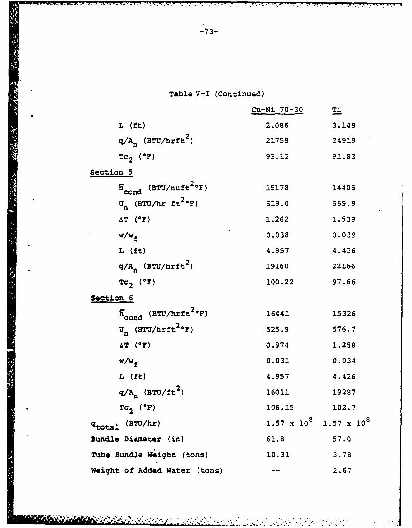
-73-
Table V-I (Continued)Cu-Ni 70-30 T1
L (ft) 2.086 3.148
q/An (BTU/hrft ) 21759 24919
Tc2 (OF) 93.12 91.83
Section 5
Hcond (BTU/nuft2 .F) 15178 14405
Un (BTU/hr ft2 F) 519.0 569.9
AT (OF) 1.262 1.539
W/wf 0.038 0.039
L (ft) 4.957 4.426
q/A n (BTU/hrft ) 19160 22166
Tc2 (OF) 100.22 97.66
Section 6
E (BTU/hrft20F) 16441 15326cond
U. (BTU/hrft2 0F) 525.9 576.7
AT (OF) 0.974 1.258
W/wf 0.031 0.034
L (ft) 4.957 4.426
q/A. (BTU/ft2) 16011 19287
Tc2 (OF) 106.15 102.7
qtotal (BTU/hr) 1.57 x 10⁸ 1.57 x 10⁸
Bundle Diameter (in) 61.8 57.0
Tube Bundle Weight (tons) 10.31 3.78
Weight of Added Water (tons) -- 2.67
h o,, , ,,-.** .w..., -, .. , n' ., ,. , " .",--, - •.. .. .: _ ... ..' . -. . "- ---." _ -
Page 79
7 a . .o .. - s- .-
-74-
this work. Table V-I shows that a smaller lighter con-
denser can be designed using Ti, but the penalty is a
requirement for increased coolant flow. Table V-2 is
an estimate of a comparable horizontal condenser using
Cu-14i 70-30 and designed to meet the same requirements
as the condensers presented in Table V-1.
C. Conclusions
This thesis has presented a design methodology for
a fluted condenser. It has shown by example in Table
V-2 that a fluted condenser can be designed which is
more compact than a horizontal condenser. Overall den-
sity of the fluted condenser tube bundle increases, how-
ever, due to the tube enhancement. This may be off-set
by foundation and structural benefits, but that is not
addressed here. With a change in material, Table V-1
shows that both volume and weight can be saved at the
cost of increased pumping requirements.
Heat transfer coefficients for condensation are
predicted by the method described in Chapter III. For
fluteq which are of the size 12-24 mils in amplitude,
increases in the heat transfer coefficients for con-
densation are greater than eight times that predicted
Page 80
-75-
Table V-2
Comparison Between a Horizontal and a Fluted Condenser*
Horizontal VerticalD (in) .625 .625
t (in) .065 .065
a (mils) - 18
a/p - .13869
Tc1 (OF) 65.0 65.0
v (ft/sec) 8.0 8.0
W (GPM) 7900 7900
No. of passes 2 2
NT 3294 3294
Pc (in-Hg-abs) 5.0 5.0
h sc (BTU/hr 2F) 2000 2000
K (BTU/hrft*F) 17.0 17.0
L (ft) 14.85 12.0
Uo (BTU/hrft2 OF) 435.8 538.6(Un=509.3)
!T (OF) 12.07 1.639
(q/A 0 ) (BTU/hr ft ) 19627 24257(q/An2293N
Tc2 (OF) 106.15 106.15
1.57xi08 1.57x10 8
Bundle Dia. (in) 53.4 61.8
Bundle Wt (tons) 9.68 10.31
*Material for both is Cu-Ni 70-30
&N
Page 81
-. - ,..7 7 - 7777771.-.7777. !-7.
-76-
by the Nusselt analysis for horizontal tubes. Stress
concentrations may be a concern for submarine use, but
by limiting the amplitude-to-pitch ratio, stresses can
be kept below an acceptable yield criterion. Great
gains in weight and volume savings could be realized
with enhancement on the cooling water side of the tube
in addition to vertical flutes.
D. Recommendations
Because thermal resistance is treated in series,
the gains made on the condensation side of a tube may
not be fully realized because of the insensitivity of
cooling water flow and resistance due to scaling or
fouling.
Further investigation is required to consider the
following:
1. Internal enhancement: Tremendous gains may be
realized by increasing the heat transfer co-
efficient of the coolant. An internal fin
arrangement could accomplish this. Drawbacks
to such arrangements are susceptibility to
fouling and tube inspectability.
................ . . . . .
.........................
Page 82
-77-
2. Biofouling: The compactness of a titanium
marine condenser, or possibly an aluminum
stationary condenser, may be to no avail if
they are rapidly blocked or fouled by marine
organisms. Active and passive protection
systems must be investigated which retard or
prevent biofouling, and if these are not
feasible, an in-service cleaning method must
be considered.
3. Scaling: This allowance is a bona fide guess.
With new materials, such as titanium, investi-
gation into scaling allowances and mechanisms
would allow a less conservative approach to
condenser design.
4. Experimental Data: This is an absolute neces-
sity. None has been provided with this thesis
because very little is available in the liter-
ature concerning fluted tubes. A criticism of
the literature cited is that no common termi-
nology is used, nor is design or zero point data
usually provided. Furthermore, most work on
fluted tubes has been performed with ammonia
and various regrigerants.
- ..!*~ . *
Page 83
-78-
E. Summary
A proposal has been made in this thesis to design
a lighter more compact marine condenser. Calculations
have been presented for selecting different condenser
tubes for submarine use. Alternative materials have
been considered and a comparison condenser design has
been presented. A methodology for calculating the heat
transer coefficient for fluted tubes has been presented,
and this is incorporated into the condenser sizing pro-
cedure.
Page 84
-79-
APPENDIX A
Condenser Tube Stress Calculations
Nomenclature
a amplitude of the flute (in)
d tube diameter (in)
h design depth (ft)
p pitch of the flute (in)
P pressure (psi)
t tube wall thickness (in)
Y yield criterion (ksi)
YS yield stress (ksi)
&stress intensity factor
a stress (ksi)
r
: }cylindrical coordinates
z
Subscripts
i inner diameter
o outer diameter
x extreme diameter
" ' ' I " ' '.. . ' " ',, . " " - " " ...-,. ." , , • " -" . .- ' . .- . . . " ...
Page 85
-80-
The general equations for stress in a thick walled
eon-fluted tube are [35]:
Pi -- + 0 [(d / d )2 _ (d0/a) 2]r (2" (A.1)
d O/d i)2 -1
Pi~~d0 /a 2 + - 0 ( 0 d)2 +( 0 d 2
= (A.2)ae - ~(do/di) 2 - 1 A2
a - P (this is because the tube sheet (A.3)
distributes external pressure on
the ends of the tubes).
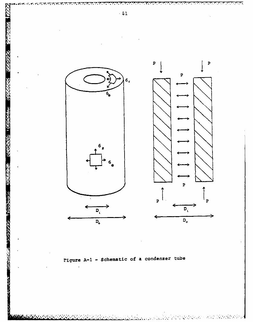
These stresses are shown in Fiaure A-I. For a condenser,
PO << Pi and equations (A.1) and (A.2) simplify to:
- Pi(do/d)2 - I
ar = (A.4)
(do/d )2 1
Pit(do/d)2 + 1]8 " d0 ) (A.5)
.
- . . S o/di - . . . . .
Page 86
-6P
6 4-
.4 p
P
DD
r'igure A-1 Schematic of a condenser tube
---- qt\
Page 87
-I! M . 1 .09 - . - . . .II-:
-82-
Maximum stresses occur at the inner diameter when d di
a x -P (A.6)rmax
a P l+ 2 (A.7)emax (do/di) 2 _
a2 = -Pi (A.8)
The failure criterion used is the mises yield
criterion, Y [35,36] where
, { [(ao,ool 2 + -o)2 +o.- 2] 1'2Y. { Le)+ (az-ar (A.9)
For a smooth surface tube this reduces to
Y2 P i + 12 (A-10)(d 0/d,) 2 -'
or
Y pi amax
1 mI
n4
Page 88
-83-
For a fluted tube, a stress concentration occurs at
the bottom of the flute valley. The mechanical restriction
to selecting a fluted tube geometry is to have maximum
stresses in the fluted tube which do not exceed a yield
criterion which is no greater than the yield criterion for
a smooth tube. Since a r- 0 at the surface of the tube,
the Tresca yield criterion is appropriate in the form:
6 a - CZflute (A.1)- " 2
or
Y= PiY Pi4 asflute
The tangential stress for the flute tube at the bottom of
the flute, where d = do , is
Pi I(dx/do)2 + 1]
ae ( 2- (A.12)
and d x -d 0 + 4a (A.13)
Page 89
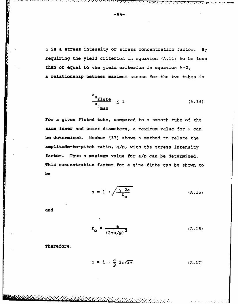
-84-
a is a stress intensity or stress concentration factor. By
requiring the yield criterion in equation (A.11) to be less
than or equal to the yield criterion in equation A-2,
a relationship between maximum stress for the two tubes is
flute < 1(A.14)
emax
For a given fluted tube, compared to a smooth tube of the
same inner and outer diameters, a maximum value for a can
be determined. Neuber [371 shows a method to relate the
amplitude-to-pitch ratio, a/p, with the stress intensity
factor. Thus a maximum value for a/p can be determined.
This concentration factor for a sine flute can be shown to
be
C + 2a(A.15)0
and
ra 2 (A.16)(2va/p)
Therefore,
1 + a 21, 7 (A.17)
• , ,,,, ,, * ,j -- **I* - L tq ,,n. !Llr .. '*r ., N.. .'.'!.-._-. .. ' .. .
Page 90
W U8
- A i- - . * * -. .. . -• - * "7 .- -... 7 7 .t.
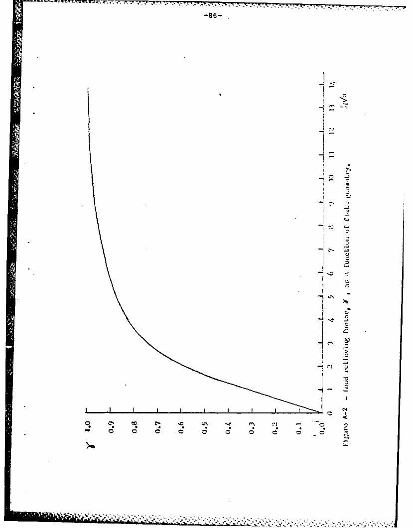
-85-
y is the load relieving factor which is described in
reference [37] and accounts for the presence of many flutes
on the surface of the tube. It is presented in Figure (A-2).
Y can be related to some mechanical property of the
tube material such as yield stress or fatigue limit. For
a submarine, a very conservative safety factor of 5 can be
assumed [381. Therefore,
Y < .2YS (A.10)
From reference [21
P4 = h/2248 Ksi (A.19)
with h, the design depth in feet.
Then for a smooth tube
.2YS - 2 [ + (A.20)(d0/di)2 1
and for a fluted tube
24 (d /di) 2 -1
L..i 2A .2 1)
j' N&N*
Page 91
-- - - - * **..- -. * - * --..-- *--..--.-*- --- '- .*.. -*. -- .*-- -
-86-
K>3
I --v -sj
-~-- -~
- .** -
-i 01~~* C-,
I -~
92
-1~**~ 0
o C~- %.O -? CI~~ -oI.- 0
. *~~~t*t3~ **.3 ~ 3 3 3 3-- --
Page 92
-87-
Both of these equations contain the constraints due to
material strength, design depth, and tube geometry. The
tube wall thickness for a smooth tube can be readily cal-
culated from equation (A.20), and the flute limitations
can then be determined from equations (A.19) and (A.17)
which will ensure that the yield criterion is not violated
due to stress concentrations.
An example calculation is provided.
EXAMPLE
Two different materials are considered for a 2000 ft
design depth condenser. These are Cu-Ni 70-30 and Ti.
Other specifications are:
do = .625 in
a - .018 in
d x= .697 in
YS(Cu-Ni) - 25 Ksi
YS(Ti) - 40 Ksi
From equation (A.20), the inner diameter, di, can be
calculated and hence the wall thickness, t. Wall thick-
ness, however, is rounded off to the nearest even gauge.
I 'T -:,- ;,-: .............'.....--.---....-...-..-..-.-.. ...... .m W | t~ ,& ; &---:'':-, '.;:' ", , .-,.' .. ' "'. '. .-. ,. ',' .. - .. '., .' .- ' '
Page 93
-88-
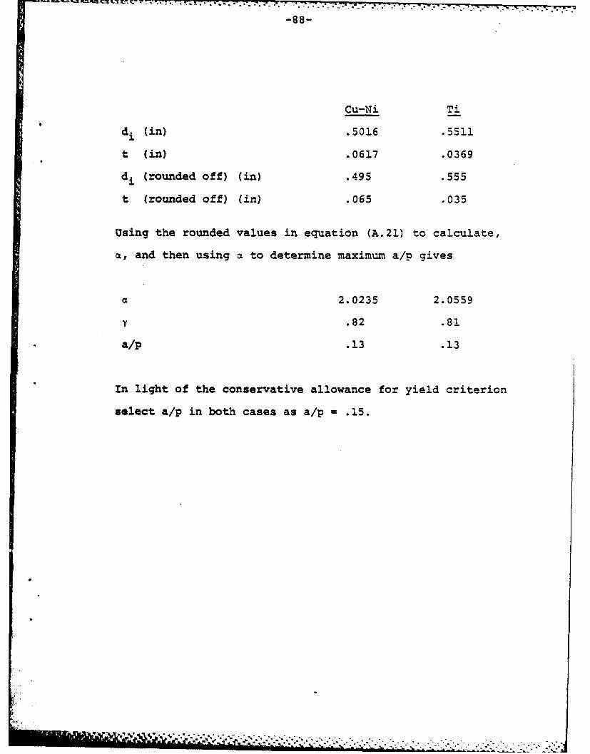
Cu-Ni Ti
d (in) .5016 .5511
t (in) .0617 .0369
di (rounded off) (in) .495 .555
t (rounded off) (in) .065 .035
Using the rounded values in equation (A.21) to calculate,
a~, and then using al to determine maximu~m a/p gives
2.0235 2.0559
'Y.82 .81
*a/p .13 .13
In light of the conservative allowance for yield criterion
select a/p in both cases as a/p -. 15.
Page 94
- .- '.. . . . . . . . . . . . . . .
-89-
APPENDIX B
Calculations for Condensate Film Thickness
Nomenclature
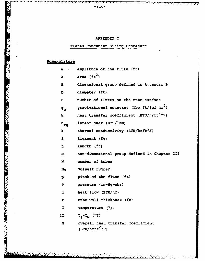
a amplitude of the flute (ft)
A area (ft2)
B dimensional group defined in equation (B.6)
gc gravitational constent (Ibm ft/lbf hr2 )
h heat transfer coefficient (BTU/hrft 2F)
hfg latent heat (BTU/lbm)
K thermal conductivity (BTU/hrftOF)
Nu Nusselt number
p pitch of the flute (ft)
P pressure (lbf/ft2)
q heat flow (BTU/hr)
r radius of curvature of the fluted sur-
face (ft)
S v flute half perimeter (ft)
Sc flute arc length on which iondensing
occurs (ft)
T temperature (OF)
AT Ts - Tw (OF)
V velocity (ft/hr)
Page 95
-90-
S
y tube surface coordinates
z
Greek letters
CL height of the condensate in the center
of the flute (ft)
r mass flow in S direction per unit length
(lbm/hrft)
condensate film thickness (ft)
8angular representation of a point
along the flute surface
U dynamic viscosity (lbm/hrft)
0 density (ibm/ft3 )
a surface tension (lbf/ft)
* non-dimensional group defined in eqn (B.12)
non-dimensional group defined in eqn (B.6)
Subscripts
c coolant
f at flooding conditions
i inside
n nominal
o outside/initial conditions
-- -- " . k - *.t.. .1 - " *- - " - - '. - " - - - .- - - - . - - - . .-.
.. - . . . . . . . . . . . ,.? , .. . .. " -
Page 96
s saturation
w wall
average
Page 97
-92-
The surface considered is shown in Figure 111-2.
The following assumptions are stated explicitly and apply
to Figure 111-2,[7,9,12,13].
1. The flow of the condensate from peak to valley
on the flute surface is thin laminar flow.
2. Because the film is thin, intertia forces are
negligible.
3. There is no interfacial shear stress between
the liquid and the vapor.
4. There is no flow in the y direction. Flow in
the z direction occurs only within the trough
of height a.
From a momentum balance on the surface specified,
dV = dP d (B.1)
d y
Integrate this with boundary conditions
dV s- - 0 at y =
and
Vs Oat y =0
- 'r _.'w,_. ' X , .! .. -.? ......-... ,. ... . . . . .
Page 98
-93-
The equation for velocity is
VS dp 2 -yj (B.2a)
and
1 f VSdy 1 dP (B.2b)VS = _U Vsdy , TS
0
Define the mass flow rate per unit length, .
r - 62. 3 (B.3a)
V.'-d 3
and
dr. - 0 - (B 3b)
From an energy balance
qhA -! -h d (B.4)
v BdrSolve eqn (B.4) for T- and set equal to eqn (B.3b).
="S
Page 99
17AD-Ri34 e63 MARINE SURFACE CONDENSER DESIGN USING VERTICAL TUBES 2/
WAIC ARE ENHANC'ED(U) NAVAL POSTGRADUATE SCHOOLMONTEREY CA C G BARNES JUN 81
UNCLASSIFIED F/G 13/i Nm EE hMiEEmhohEEEEohh
Page 100
. .... ! - : ,' +
" ' '' '- -
.. . . . . .. .
111.0-ii
111.25
EUIH ----- -:
MICROCOPY RESOLUTION TEST CHARTNATIONAL BUREAU OF STANDARDS- 1963-A
Iz
Page 101
..94..
=K.T = - ds [i..4 I I (B. 5a)'fgas
which, for constant physical properties becomes
iUK4T 6 d 3 d (B. Sb)
Define s2,
uKL BAT (B.6)Pah fg g ca a
So eqn. (B.5b) may be written as
a d 3dIl(-c
n -1 - I s [63(~j (.
For a sine function flute the radius of curvature, r, is
arLr2a{l ra 2 2 3/2
The aclength, S, is
- sin d (B.8a)0
Page 102
-95-
r. as shown in Figure 111-2.
9 c ( hi) at Sc (B.8b)
For given values of a, p, and a, eqn. (B.Sc) can be solved
numerically [7,12]. By syrmuetry
da
w - Oat 9=0
Eqn. (B.5c) becomes
dS a 4
S=O4=0
which gives the initial value for the boundary layer
thickness, ao .
1/
o= 30 (B. 10)
Integrating equation (B.5C) gives
i .. .--. > -. "* '" -":" ". -" " .. . ." . ." - .'.. -.. ''.... . . .. ,
Page 103
. . . . . . . . . ..• ..
r S
_d . 3aiS S !L s (B.11)
r 0 0o-
., Define 4 such that
S f dS (B. 12a)
and by finite difference
ASn
= as n (B.12b)
* where
ASn - Sn+1 - Sn (B.13)
Eqn. (B.11) may be written in the form of a trapezoid rule
integration to give
1 1 3aQ +IS (B.14a)Fn Enl T Jn+i n] Trn hic b L Iom
which becomes
• .: ,*.*,.... -. , - . -.. .- .- , . .- ,.,- , . -.. - . -.....-- .-. . .
Page 104
• . . . ..o. . ,-- ..
-97-
-- n -- 6 20 n + + (B.14b)i rn rn+l 6 L
can now be determined for Ae increments, with the initial
conditions
60 from eqn (B.10)
0o0 0
So 0
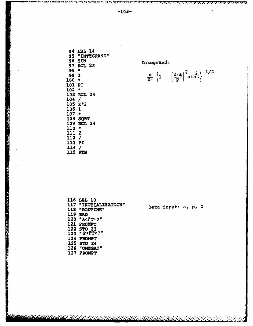
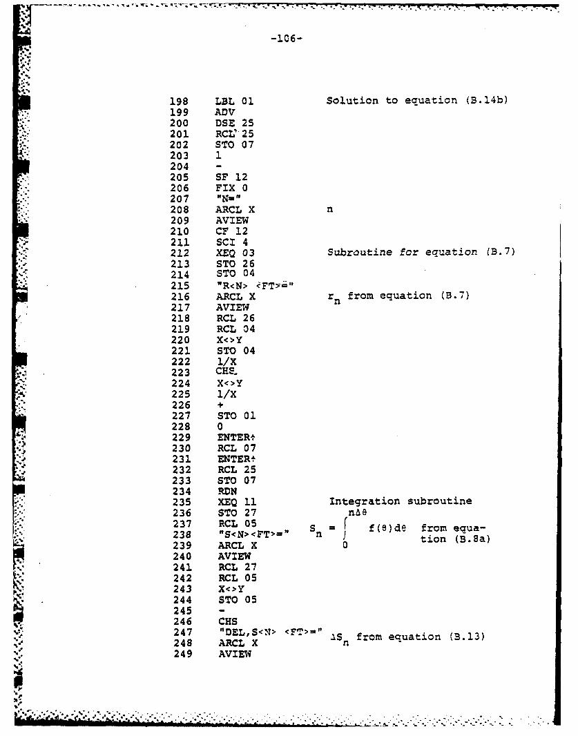
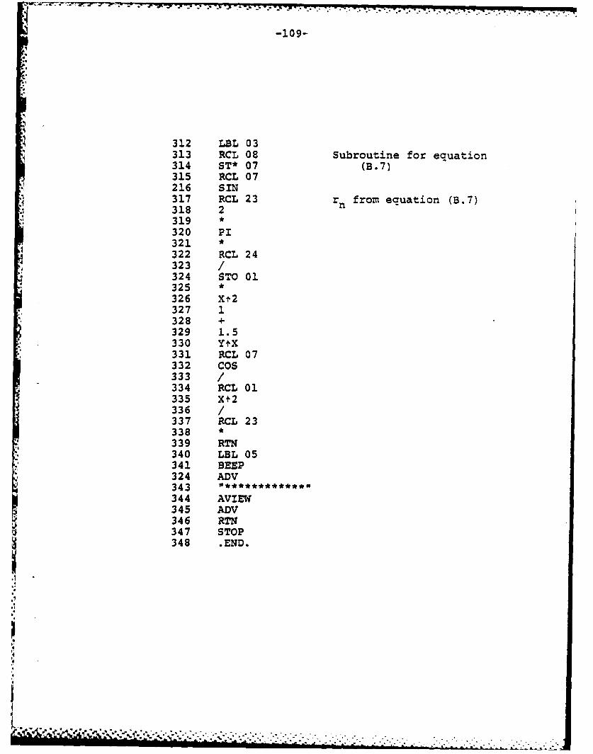
Addendum 1 to this appendix is a program written
for a programuable calculator to solve eqn. (B.14b)
The average film thickness of the condensate can
be calculated
S1 - 1f S M10()(B.15)
0
Define the heat transfer coefficient, h
h= K (B.16)
The average heat transfer coefficient is
Sc
S 1 dSK(B.17a)T sc v s c
-0
Page 105
-98-
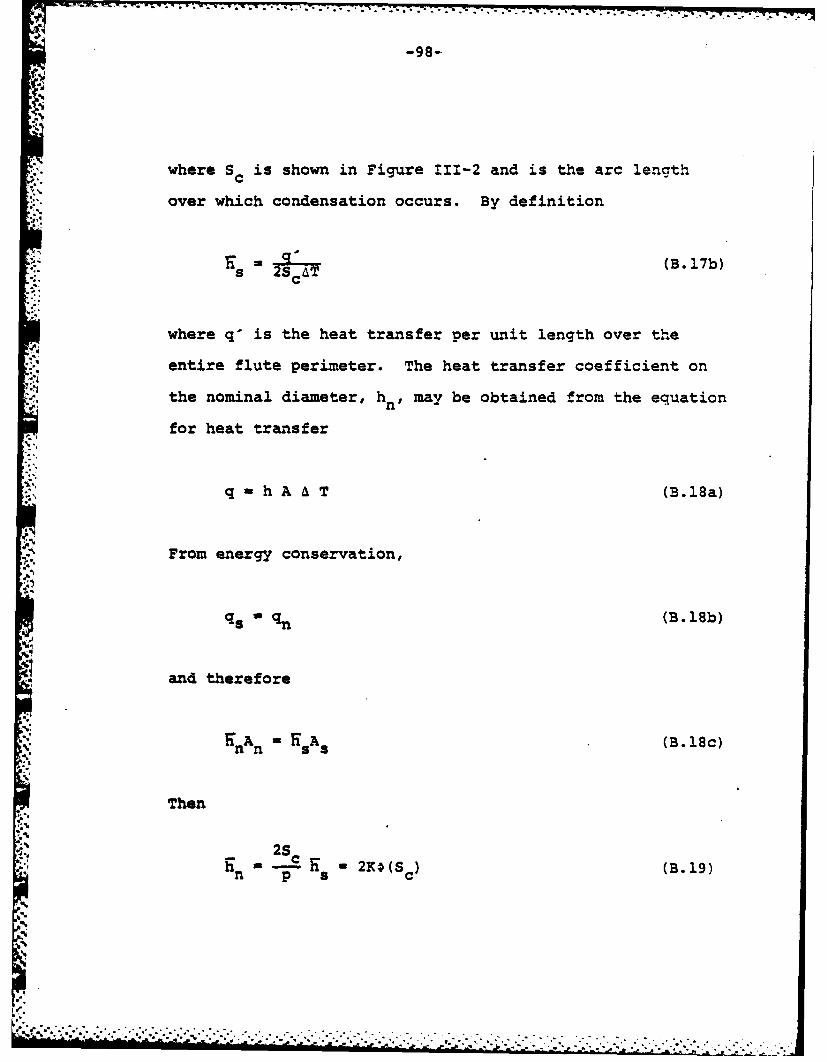
N
where Sc is shown in Figure 111-2 and is the arc length
over which condensation occurs. By definition
Tj s(B. 17b)
where q' is the heat transfer per unit length over theientire flute perimeter. The heat transfer coefficient on
,! the nominal diameter, hn, may be obtained from the equation
for heat transfer
q hA A T (B.18a)
From energy conservation,
,,
qs " 5 (B.18b)
and therefore
nA n " KsA5 (B.18c)
Then
2Sh ..= - 2KO(S (B. 19)n p a
,-
a-
i.4b.. . . f '" ' " ' " " " : " " ' " , ''-. , - ''' ' -. ' ' . '- ' ' v . '" --. " '' . . . - '
Page 106
tot .. *
-99-
A bluselt number may be defined as
Nu 20(S) (B. 20a)
and for S c S S
Nu -Nu 0(S)v 2(V (B.20b)
From equations (B.6), (B.8a), (B.8b), and (111-10)
f a /,ww)(.1
Page 107
-100-
APPENDIX B - ADDENDUM I
Calculator Program for the
Solution of Equation (B.14b)
This program was written for a Hewlett Packard
HP-41C programmable calculator. It requires two addi-
tional memory modules, and a printer is highly desireable.
Twenty six (26) memories must be allocated. The program
is run by simply executing the program label, "DELTA".
The calculator will respond by inter-actively asking for
inputs. The required inputs are:
a, p, and n.
The outputs are for n - 0 to n - 60,
rn ' S n' &Sn ' 8n , and n
The method of. solution is exactly as explained in
Appendix B. Equation (B.Sa) is solved by a 10 point
Gauss-Legendre quadrature method for a sine geometry flute.
,I - ,,.-, . . .. .. . .
' , . _.,- .- <. .. . ... .. . . . . . .. .. . - -. -. . .. . .. ..
Page 108
-101-
01 LBL "DELTA"02 "COMPUTER BOUNDA"03 "DRY LAYER"04 AVIEW05 "AS A FCT. OF AR"06 "C LENGTH.1"07 AVIEW08 ADV09 "************,
10 AVIEW11 "S<N>/PHI<T>-DEL"12 "TAqi >, AVG"13 AVIEW14 "************"15 AVIE.16 ADV17 CLRG Clear all rtemories18 SCI 419 1.488743390 Z-i20 STO 1021 2.955252247 E-122 STO 1123 4.333953941 E-124 STO 1225 2.692667193 E-126 STO 1327 6.794095683 E-1 Loading into memory28 STO 14 locations weighting29 2.190863625 E-1 lues nesayno30 STO 15 values necessary for
31 8.650633667 E-1 integration by32 STO 16 quadrature
33 1.494513492 E-134 STO 1735 9.739065285 E-136 STO 1837 6.667134431 E-238 STO 1939 GTO 10
Page 109
-102-
40 LBL 1141 "INTEGRATION"42 STO 2143 X<>Y44 STO 2245 -46 247 Integration by Gauss-48 STO 22 Legendre Quadrature49 RCL 22 b50 RCL 21b51 + f(x)d52 2 f fx53 a54 STO 2155 056 STO 00 b-a 10 f 1Z ba)+i57 10.021 2Wf 258 STO 25 i=159 XEQ 1260 XEQ 1261 XEQ 1262 XEQ 1263 XEQ 1264 RCL 0065 RCL 2066 *67 RTN68 LBL 1269 "QUADRATURE SUB-"70 "ROUTINE"71 RCL IND 2572 ISG 2S73 STO 2274 CRs75 RCL 2076 *77 RCL 2178 +79 XEQ 1480 RCL IND 2581 *82 ST+ 0083 RCL 2284 RCL 2085 *86 RCL 2187 +88 XEQ 1489 RCL IND 2590 *
91 ST+ 0092 ISG 2593 RTN
.':.':..',,, _,.' . -..'.-. .. * - * .. * . ***.. . *. *, -... .
Page 110
-103-
94 LBL 1495 "INTEGRAND"
96 SIN Integrand:97 RCL 2398 * 2 1/299 2 +f r-a12 .)/
100 * 2r k p)Sff101 PI102 *103 RCL 24104 /105 X 2106 1107 +108 SORT109 RCL 24110 *111 2112 /113 PI114 /115 RTN
116 LBL 10117 "INITIALZZATION" Data input: a, p, Q118 *ROUTINE"119 RAD120 OA<FTV ?121 PROMPT122 STO 23123 " P<?T>?"124 PROMPT125 STO 24126 "OMEGA?"127 PROMPT
Page 111
-104-.
128 3 Calculation of initial129 * values (continued)130 RCL 23
*~1131 *132 STO 09133 PI = 7/60134 60135 /
s 136 STO 08137 0138 STO 02139 STO 05140 STO 06141 STO 26142 RCL 23143 RCL 24 r from equation (B.7),144 /145 2 = 0146 *174 PI s =0148 *0149 Xt2 0 =0150 1/X151 RCL 23152 *153 STO 04154 ORO<FT>-"155 ARCL X156 AVIEW157 0158 "SO<FT>'-"159 ARCL X160 AVIEW161 FIX 3162 "P1IO"163 ARCL X164 AVIEW
"t
-+ , - , ,.-, ;,..,. . ,+ .-. >..... , ,.... :, .. . ..... . .. ..... .. . - i
Page 112
168
i -105-.
4; 4
.
9.6
17 P'174
165 RCL 23 Calculation of initial166 RCL 24 values (continued). 167 /3,. 68 2169 *
170 P173. *172 XI2173 3174 *175 3.
176 +177 RCL 23
"4178 *,.179 I/X
14; 180 RCL 09
.188 *182 SQRT183 SCRT184 RCL 24185 *186 2187 /188 PI189 /190 STO 03191 SF0 4192 "DELTAO<FT>=" 6 from equation (B.lI0)193 ARCL X o1.94 AVIEW195 23.96 STO 25197 SF 01
r!J
pf~ i i ; & ,,,:~ :; ---
Page 113
198 LBL 01 Solution to equation (B.14b)199 ADV200 DSE 25201 RCV - 25202 STO 07203 1204 -
205 SF 12206 FIX 0207 "N"208 ARCL X n209 AVIEW210 CF 12211 SCI 4212 XEQ 03 Subroutine for equation 1B.7)213 STO 26214 STO 04215 "R<N> cFTY>-"216 ARCL X rn from equation (B.7)217 AVIEW218 RCL 26219 RCL 34220 X<>Y221 STO 04222 1/X223 CHE.224 X<>Y225 1/X226 +227 STO 01228 0229 ENTER+230 RCL 07231 ENTERt232 RCL 25233 STO 07234 RDN235 XEQ 11 Integration subroutine236 STO 27 nA8237 RCL 05 S = f(O)de from eaua-238 "S<N><FT>" n I tion (B.8a)239 ARCL X 0240 AVIEW241 RCL 27242 RCL 05243 X<>Y244 STO 05245
. 246 CHS247 "DEL,S<N> <FT>=" Sn from equation (B.13)248 ARCL X n249 AVIEW
-
." ;"" o. - ,,-. -.. .,,....... ..... . . -]'{'u'|l'J"f........... .. ... .. .,:,... .. "'". -:- . -- .- .- - "
Page 114
-107-
250 STO 060 251 RCL 07
252 STO 25253 RCL 03254 STO 07255 SCI 4
"-" 256 FC?C 01257 XEQ 02 Subroutine tc iterate for258 "DELTA<N> <FT>-" 3 from equation (B.14b)259 ARCL x260 AVIEMI261 RCL 06262 RCL 07263 /264 RCL 02 1n from equation (B.12b)265 FIX 3
266 "PHI<N>="267 ARCL X268 AVIEW269 +270 STO 02271 2272 ST+ 25273 RCL 25274 63275 X-y?276 GTO 05277 GTO 81
-47
-.
'I
Page 115
-108-
278 LBL 02
, 279 RCL 03 Subroutine to iterate for
280 I/X 6n from equation (B.!4b)281 RCL 06282283 RCL 02 <- i - 10- 7
284 2285 *286 +287 RCL 06288 *289 2
.9.0x" 29i /291 RCL 09292 *293 RCL 01294 X<-0?295 GTO 04296 /297 3298 1/X299 Y+X300 SCI 4301 RCL 03302 X<>Y303 STO 03304305 ABS306 1 E-7307 X<-Y?308 GTO 02 For n = 60, 660 has no309 LBL 04 solution. Replace S6310 RCL 03 60311 RTN 59*
.4.
.3
Page 116
-109-
312 LBL 03313 RCL 08 Subroutine for equation314 ST* 07 (B.7)315 RCL 07216 SIN317 RCL 23 rn from equation (B.7)318 2i 319*
320 PI321 *322 RCL 24323 /324 STO 01325 *
326 Xt2327 1328 +329 1.5330 Y+X331 RCL 07332 COS333 /334 RCL 01335 Xt2336 /337 RCL 23338 *339 RTN340 LBL 05341 BEEP324 ADV343 "******
344 AVIEW345 ADV346 RTN347 STOP
348 .END.
.I
4
.
Page 117
* .7 77. 7.7 7. 77r~t"
APPENDIX C
Fluted Condenser Sizing Procedure
Nomenclature
a amplitude of the flute (ft)
A area (ft )
B dimensional group defined in Appendix B
D diameter (ft)
F number of flutes on the tube surface
9C gravitational constant (Ibm ft/lbf hr2)
h heat transfer coefficient (BTU/hrft2 OF)
hfg latent heat (BTU/ibm)
k thermal conductivity (BTU/hrft*F)
1 ligament (ft)
L length (ft)
M non-dimensional group defined in Chapter III
N number of tubes
Nu Nusselt number
p pitch of the flute (ft)
P pressure (in-og-abs)
q heat flow (BTU/hr)
t tube wall thickness (ft)
T temperature (0-)
AT TS-T w (OF)
U overall heat transfer coefficient
(BTU/hrft2 F)
- . '. 5 '* - .2.
• . . _ - ., .. . ,, . .'. - -. ,. .. . - -o . . . .. -. - -. - . - .. S ..
Page 118
V velocity (ft/hr)
w axial mass flow of liquid (lbm/hr)
Wt weight (ibm or tons)
Greek letters'
dynamic viscosity (lbm/hrft)
P density (ibm/ft )
a surface tension (lbf/ft)
non-dimensional group defined in Chapter III
S.ubscripts
B tube bundle
c coolant
D tube bundle diameter
f at flooding conditions
i inside
n nominal
o outside
s saturation
T total
w wall
sc scale
x cross section
symbols
average
I°:oe %"* ," "• .. . • , .- - ....."- "' ' ~ i rJ '.f i ' ._ 4*, . ' * - '.-. .. °4. a.4', *-' ., -_'''.2 -'- ,', ,.-. ..** * * . . .. ,
, , n i nnn i n uulW llnlmh llln hna " nl' nn, al " ; " """' " "'"- "":"'' ' '2' ' a. ' "-.
Page 119
This procedure will consist of an example which
sizes a submarine condenser. As required in reference
(11], a submarine condenser has an even number of passes
for the coolant flow. A maximum length will be specified-
Design Specificatons
Design depth - 2000 ft
Material - Cu-Ni 70-30
Tube: D0 - 5/8 in (.625 in)
t - .065 in (16 Gauge)A3
a = 18 mils (1.50 x 10- ft)
a/p - .31205
SF - 36
Dn - .643 in
Coolant: Sea water
Tc I = 65.0*F
Vc - 8.0 ft/sec
W c - 7900 GPM (4.0559 X 10⁶ ibm/hr)No. of passes = 2
No. of passes - 3294
Condensate:
Pressure - 5.0 in-Hg-abs
Tsat 133.7 0F
P. " 61.554 ibm/ft 3
,A
,.4% .-,.-. . ,'.,,- --- -. ,,- , ,:*-. :... ... ., .-- - ...-. -. :.... .
Page 120
-113-
k& - .376 BTU/hrftOF
a£ - .00459 lbf/ft
hfg - 1017.4 BTU/Ibm
li - 1.20 lbm/hrft
Thermal conductivity of tube wall - 17.0 BTU/hrftOF
hscale = 2000 BTU/hrft2,F
Total tube length per pass = 12.0 ft
Preliminary calculations:
NUoQ 1 / 4 - 4.612 from Figure 111-4
B - 3.7649 x 10 "12 ft/OF eqn. (111-7)
Wf - 6.7157 ibm/hr eqn. (111-10)
The condenser will be segmented into 6 sections as
shown in Figure (IV-i). The length, L, of section 1
will be that length required for condenstate run-off of
w/wf - 0.060. This length will be used for sections 2,
5, and 6. The lengths for sections 3 and 4 will be
the length necessary to make each pass total length
equal to 12.0 ft.
~'V'W~v:&%
Page 121
-114-
A. Calculation of L1
1. Specify W/Wf
then M = .0820 from equation (ill-19)
2. Assume Tc 2 = 66F; i = 1
3. Assume L - 10.0 ft; i 1
a. Solve for Ti from equation (111-29)
.4" b. Solve for (q/An)i from equation (111-25)
c. Solve for Li+ 1 from equation (111-23)
d. Reeat a, b, and c until Li = Li + 1
4. Solve for Tc2j+l from equation (111-24)
5. Repeat 3 and 4 until Tc2j , Tc2j+l
Results are shown in Table C-l.
3. Calculation of {w/wf) 2
1. Specify L2 = L1 - 4.957 ft.
2. Assume Tc2 - 77.36°F; j 1
3. Assume AT - 0.500F; i = 1
a. Solve for (q/An)i from equation (111-25)
b. Solve for (w/wf)i from equation (II--23)
c. Solve for M from equation (111-19)
d. Solve for ATi+ from equation (i11-29)
e. Repeat a-d until AT. - ATi+
'- [' " ; k T..........> --..- '.... ".,."-., .......... ...........
Page 122
w% in0C P n
*E-
00
r4 wm o m
-- A-4E-4 q
0.~.4 N ie r-4 4" m (n.%a000
14V~ 444~E 40q .w W-
04. .0 r-
N- N N04NMI'-4P4
X.~
Page 123
4. Solve for Tc2 4 from equation (111-22)2jn
5. Repeat 3 and 4 until Tc 2 j = Tc 2 j+1
Results are shown in Table C-2.
Calculation of all remaining length sections pro-
ceeds as for section 2, with the desired length speci-
fied. The coolant exit temperature for each section is
4 the inlet temperature for the succeeding section.
Results for the entire condenser are shown in Table C-3.
A check on the solution to equation (111-22)
verify the results in Table C-3.
0774_ a. 2307 f /)]9226 FK3 Pc ahfq .230L A62(fT p L uATJ
where f~a/p] u01 /
This should be compared to
(q/A n4TH shown i.n Table C-3.
Table C-4 shows this comparison.
Page 124
P-4 o
-117-
-4.4
=at cca kn w00% 0 %c -c oc -+ 4C 0% '.0 '0% CAm0% 0 0 4
-P -WELe
Ch NNNN InN M Mri o- f- M -o- N M -4 -4-4
.. . . . . . . .U.,-
r-00
N % N4
*e.. %aI -4 r- a HN0 om - 0 oe
e. 44 0--i~e4 CO0 00 ONNC4( P1N (44N N cccw0 %0 w 40o~'. P-. w to w 'o. r14D%0w E
C4 N NNN C4 C N C e "N NNN C
44 -P.. ( qU N g 1q0% M L a f)C0 t0C r0%
"70 LM Im-4 0
0CON N
-~1 4'
f" 4% -4( nV P M- 4NM-
4J
Page 125
C~4 LM
* C~0 LMe~ q LM m% CA0 0 0~
F-4 LM LA .tn
V N *o r. C4 NA ' -
LAO4 0 LA .4 * 0 C
r4 P LA - Ln r-I a % F-4
fnl CI. 0o %%~0 CA C'4 (N
ON1 C% co0 q rl%C* 0 r A iI -4 0% r
u- L -4 LA r-4 0 Ci Ni 0 0
GIN
* C 0 0 en 0o E-
u u * N u-I cc cc 0 £
%c cc fnt1 LA 0 a fn
fn ta3 C4(~ ~ LA 0- (n *Q * C% ODr4 LA 0 LA u-I 0 ( N o 0o 0
041 r-
x.4 - o 4 - 0 %0 0o
a 0 % 0 cc LA LA en m 0 LA0 P-4 M-I CA 0 0% (N #
C4 r. 1 (N en% 0 %C %C ~ %0 r-I
P-4 LA F-4 LAn - 0 ~ N r- 0o1
0 I
* 0o (4 %0 410t- % '
41 en% P4 u-Ia %D LA 0 en 0
*-0 r. en ON 0%-W6-0% 0 (N 0 w 0 LA '0
uar4 LA r-4 IV C4 0 -W m~ %a0 rl
4 M 0 14.4
4L ~.1 -- - 4
1J~ 0 0 S-4 P4. Nj~
Q . E4 N N 0 0A ~ IA E-fr
Page 126
A- 119-
TABLE C-4
Comparison Between Equation (111-22)
and Calculated Results
W by iterative
Section n by eqn (22) solution
1 12322 12312
2 13206 13197
3 15313 15302
4 15812 15800
5 15190 15178
6 16452 16441
C. sizing the Tube Bundle Diameter
The number of tubes across the diameter, ND, of
a circular bundle containing NT total number of tubes is
ND M IT-N (C.1)
The geometric diameter for the individual tube used in
sizing the tube kundle is the extreme diameter, D.
Dx - D0 + 4a (C.2)
- *1.. . . .' ' i - ' ' i
. . . ." • " " " " ' " ' ' . -' ' " - - .,- • - . .
Page 127
~-12 0--
The physical separation in the tube sheet between outer
edges of adjacent tubes is termed the ligament, 1.
Minimum ligament distance is 0.212 in. (421. This limit
is set by manufacturing constraints. Thus the tube
bundle diameter, DB, is
DB = ND • Dx + (ND 1) (C.3)
For the condenser considered,
N = 65
D x = .6970 in.
D - 58.87 in.B
* Allowing 5 percent for steam flow passages,
structural members, air ejectors, and downcomers gives
an external diameter for the condenser bundle
DB -61.82 in.I•B
" '- , 4 "'".)
. .. . . ... . . .*
i I i .. .t - '
k ' : " " "" '" " ,' "" " " "" " """-'"' "'' "' -. "". " a- J '
Page 128
D. Weight Estimation of the Tube Bundlo
The weight of an individual tube can be deter-
mined by the product of the tube length, LW, tube cross
section, A and material density. Thus the weight of
the tube bundle is
WtB -A XL NT(C.4)
The cross sectional area for a sine geometry flute is
approximated by
(2 2 ?A~ x (C.5)
For the condenser considered,
A X - .1507 in2
Wt B - 23091 -10.31 tons
Page 129
-122-
REFERENCES
1. Taggart, R., Ed., Ship Design and Construction,Society of Naval Architects and Marine Engineers,New York, 1980.
* 2. Jackson, H., "Submarine Design Notes", Dept. XIII-AProfessional Summer at MIT, 1980.
3. Lecture by Mr. Dan Weiler of Naval Sea Systems Com-mand, 3211, to MIT XIII-A students on 8 January 1980.
4. "Shaping the General Purpose Navy of the Eighties:Issues for Fiscal Years 1980-1985", CongressionalBudget Office, Congress of the United States,January 1980.
5. Couhat, J., Combat Fleets of the World, 1981/81,United States Naval Institute, Annapolis, MD, 1980.
6. Rohsenow, T. and Choi, H., Heat, Mass and MomentumTransfer, Prentice-Hall, Englewood Cliffs, NJ, 1961.
7. Gregorig, R., "Hautkondensation an feingewelltenOberfl~chen bei Berucksichtigung der Oberflachen-spannung," Zeitschrift fur angewande Mathematikund Physik, "Vol. 5., 1954, pp. 36-49.
8. Zener, C. and Levi, A., "Drainage Systems for Con-densation," Journal of Engineering for Power,Vol. 96, July, 1974, pp. 209-215.
9. Webb, R., "A Generalized Procedure for the Design- and Optimization of Fluted Gregorig Condensing
Surfaces," Journal of Heat Transfer, Vol. 101,May, 1979, pp. 335-3.
10. Conversation with Professor B. Mikic, MIT on26 February 1981.
11. Military Specification, "Condensers, Steam, NavalShipboard," MIL-C-15430J (Ships), 19 June 1974.
12. Yamamoto, H. and Ishibachi, T., "Calculation ofCondensation Heat Transfer Coefficients of FlutedTubes," Heat Transfer Japanese Research, Vol. 6.,October- December, 1977, pp. 61-68.
I .l-.
Page 130
-123-
13. Panchal, C. and Bell, X., "Analysis of Nussel-Type Condensation on a Vertical Fluted Surface,"Condensation Heat Transfer, ASME, New York, 1979,
.pp. 45-54.
14. Mori, Y., Hyikata, K., Hirasawa, S., and Nakayama,* W., "Optimized Performance of Condensers with Out-
side Condensing Surface," Condensation Heat Transfer,ASME, New York, 1979, pp. 55-62.
15. Krassik, I., Krutzsch, W., Fraser, W., and Messina,J., eds., Pump Handbook, McGraw-Hill, New York, 1976.
16. Harrington, R., ed., Marine Engineering, S I4E,New York, 1971.
17. Letter from Commander, David W. Taylor Naval ShipResearch and Development Center to Commander, NavalSea Systems Command (SEA 05DC3), Ser 10310, dated7 January 1980.
18. Metals Handbook, Ninth Edition, Vols. 2 and 3,American Society for Metals, Metals Park, OH, 1979.
19. Efird, K., and Anderson, D., "Sea Water Corrosionof 90-10 and 70-30 Cu-Ni: 14 Year Exposures,"Materials Performance, Vol. 14, November, 1975,pp. 37-40.
20. Bulow, C., "Use of Copper Base Alloys in MarineServices," Naval Engineers Journal, Vol. 77, June1965, pp. 470-482.
21. Danek, G., "The Effect of Sea Water Velocity onthe Corrosion Behavior of Metals," Naval EngineersJournal, Vol. 78, October, 1966, pp. 763-769.
22. Fontana, M. and Greene, N., Corrosion Engineering,2d ed., McGraw-Hill, New York, 1978.
23. Litvin, D., and Smith, D., "Titanium for Marine* "Applications," Naval Engineers Journal, Vol. 83,
October, 1971, pp. 37-43.
24. Knudsen, J., "Apparatus and Techniques for Measure-ment of Fouling of Heat Transfer Surfaces," Con-denser Biofouling Control, S mposium Proceedins,Electric Power Research Institute, Ann ArborScience Publishers, Ann Arbor, MI 1980.
. . n l " - <, -.. . . '. . ' ' , ' ' o ",-".
Page 131
I i - o ° o
-124-
"4
25. Characklis, W., Bryers, J., Trulear, M. and Zelver,N., "Biofouling Film Development and Its Effects onEnergy Losses: A Laboratory Study," Condensor Bio-fouling Control, Symposium Proceedings, ElectricPower Research Institute, Ann Arbor Science Pub-lishers, Ann Arbor, MI, 1980.
26. Letter from Commander, David W. Taylor Naval ShipResearch and Development Center to Commander, NavalSea Systems Command (SEA 532), Ser 2722, dated23 July 1980.
27. Bell, K., "The Effect of Fouling on OTEC Heat Ex-changer Design, Construction, and Operation," Un-published, received by private communication,September 1980.
28. Blume, W. and Kirk, B., "Application of the CathelcoAntifouling System for the Control of Marine Growthin Seawater Inlets and Condensers," Condenser Bio-fouling Control, S!mposium Proceedings, ElectricPower Research Institute, Ann Arbor Science Pub-lishers, Ann Arbor, MI, 1980.
29. Conversation with Mr. Alan Fritsch, David W. TaylorNaval Ship Research Development Center, Annapolis,Maryland, on 14 June 1980.
30. Brown, B., et al, Marine Corrosion Studies, NRLMemorandum 1574, Second Interim Report of Progress,U.S. Naval Research Lab, Washington, DC, November,1964.
31. Uhlig, H., Corrosion and Corrosion Control, 2d ed.John Wiley and Sons, New York, 1971.
32. Cotton, J. and Downing, B., "Resistance of Titaniumto Sea Water," Transactions of the Institute ofMarine Engineers, Vol. 69, August, 1957, pp. 311-319.
33. LaQue, F., "Deterioration of Metals in an OceanEnvironment," Ocean Engineering, Vol. 1, March,1969, pp. 299-312.
34. Conversation with Mr. Kurt Bredehorst andMr. Walter Aerni of NAVSEA on 15 June 1980.
-. m mm*.m* *. '** .. *.*. . , ' ' ' - ' ' ' T : ' , - '.?
Page 132
9<~t 70: -
-125-
35. Crandall, S., Dahl, N. and Lardner, T., eds.,An Introduction to the Mechanics of Solids, 2d ed.,NcGraw-Hill, New York, 1972.
36. McClintock, F. and Argon, A., eds., MechanicalBehavior of Materials, Addison-Wesley, Reading,Massachusetts, 1966.
37. Neuber, H., Theory of Notch Stresses, Principles•% :-for Exact Stress Calculation, J. W. Edwards,
Ann Arbor, Michigan, 1946.
38. Conversation with CAPT Harry A. Jackson, USN (Ret.)on 18 November 1980.
39. Welty, J., Engineerins Heat Transfer, John Wileyand Sons, New York, 1978.
40. Fugii, T. and Honda, H., "Laminar Filmwise Con-densation on a Vertical Single Fluted Plate,"Sixth International Heat Transfer Conference, Vol. 2,National Research Council of Canada, Toronto,Canada, August 7-11, 1978, pp. 419-424.
41. Harrington, R., ed., Marine EngineerinS, Society ofNaval Architects and Marine Engineers, New York,1971.
42. Conversation with Hr. Henry Brawn of DeLeval Corp.,Florence, NJ, on 12 August 1980.
43. Titus, M., "Investigation of Rolled Titanium Tube-To-Tube Sheet Joints for Condenser Application,"David W. Taylor Naval Ship Research and DevelopmentCenter, Bethesda, MD, October, 1978.
-" "