Page 1
1© KEMET Electronics Corporation • P.O. Box 5928 • Greenville, SC 29606 • 864-963-6300 • www.kemet.com A4054_EDT • 5/21/2018One world. One KEMET
Benefits
• Surface mount lead terminals • Lowprofileverticalchip• Operatingtemperatureof−40°Cto+125°C• 125°C/1,000–2,000hours
Overview
TheKEMETEDTaluminumelectrolyticsurfacemountcapacitorsaredesignedforapplicationsrequiringhighoperatingtemperaturesofupto125°Candalowprofileverticalchip.
Applications
Typicalapplicationsincludeautomaticmountingandreflowsoldering.
SurfaceMountAluminumElectrolyticCapacitors
EDT, +125°C
Part Number System
EDT 107 M 010 A 9L AA
Series Capacitance Code (pF) Tolerance Rated Voltage
(VDC)Electrical
Parameters Size Code Packaging
Surface Mount Aluminum Electrolytic
First two digits represent
significantfiguresfor capacitance
values. Last digit specifiesthe
number of zeros to be added.
M = ±20% 010 = 10 016 = 16 025 = 25 035 = 35 050 = 50
A = StandardS = AEC-Q200
See Dimension Table
AA = Tape & Reel
Page 2
2© KEMET Electronics Corporation • P.O. Box 5928 • Greenville, SC 29606 • 864-963-6300 • www.kemet.com A4054_EDT • 5/21/2018
Surface Mount Aluminum Electrolytic Capacitors – EDT, +125°C
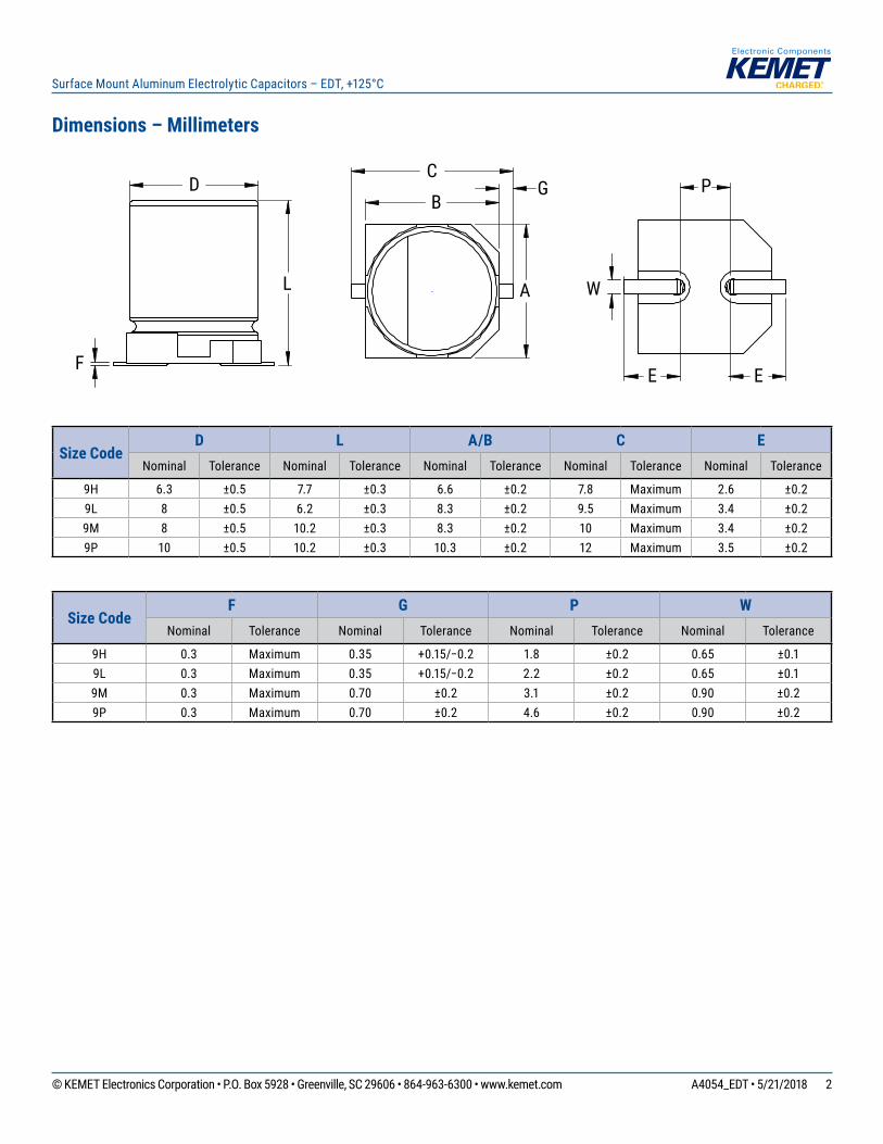
Dimensions – Millimeters
W
E E
P
A
B
C G
L
D
F
Size CodeD L A/B C E
Nominal Tolerance Nominal Tolerance Nominal Tolerance Nominal Tolerance Nominal Tolerance
9H 6.3 ±0.5 7.7 ±0.3 6.6 ±0.2 7.8 Maximum 2.6 ±0.29L 8 ±0.5 6.2 ±0.3 8.3 ±0.2 9.5 Maximum 3.4 ±0.29M 8 ±0.5 10.2 ±0.3 8.3 ±0.2 10 Maximum 3.4 ±0.29P 10 ±0.5 10.2 ±0.3 10.3 ±0.2 12 Maximum 3.5 ±0.2
Size CodeF G P W
Nominal Tolerance Nominal Tolerance Nominal Tolerance Nominal Tolerance
9H 0.3 Maximum 0.35 +0.15/−0.2 1.8 ±0.2 0.65 ±0.19L 0.3 Maximum 0.35 +0.15/−0.2 2.2 ±0.2 0.65 ±0.19M 0.3 Maximum 0.70 ±0.2 3.1 ±0.2 0.90 ±0.29P 0.3 Maximum 0.70 ±0.2 4.6 ±0.2 0.90 ±0.2
Page 3
3© KEMET Electronics Corporation • P.O. Box 5928 • Greenville, SC 29606 • 864-963-6300 • www.kemet.com A4054_EDT • 5/21/2018
Surface Mount Aluminum Electrolytic Capacitors – EDT, +125°C
Environmental Compliance
Asanenvironmentallyconsciouscompany,KEMETisworkingcontinuouslywithimprovementsconcerningtheenvironmentaleffectsofbothourcapacitorsandtheirproduction.InEurope(RoHSDirective)andinsomeothergeographicalareaslikeChina,legislationhasbeenputinplacetopreventtheuseofsomehazardousmaterials,suchaslead(Pb),inelectronicequipment.Allproductsinthiscatalogareproducedtohelpourcustomers’obligationstoguaranteetheirproductsandfulfilltheselegislativerequirements.Theonlymaterialofconcerninourproductshasbeenlead(Pb),whichhasbeenremovedfromalldesignstofulfilltherequirementofcontaininglessthan0.1%ofleadinanyhomogeneousmaterial.KEMETwillcloselyfollowanychangesinlegislationworldwideandmakeanynecessarychangesinitsproducts,wheneverneeded.
Somecustomersegmentssuchasmedical,militaryandautomotiveelectronicsmaystillrequiretheuseofleadinelectrodecoatings.Toclarifythesituationanddistinguishproductsfromeachother,aspecialsymbolisusedonthepackaginglabelsfor RoHS compatible capacitors.
Duetocustomerrequirements,theremayappearadditionalmarkingssuchasleadfree(LF)orlead-freewires(LFW)onthelabel.
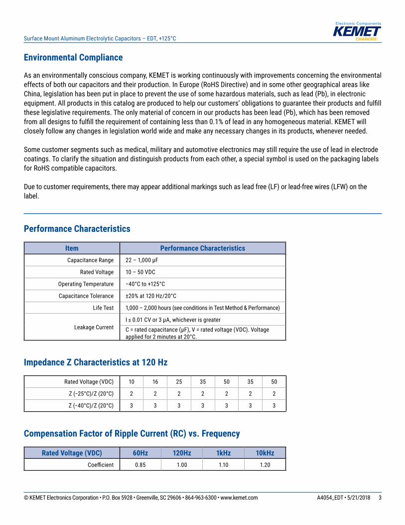
Performance Characteristics
Item Performance CharacteristicsCapacitance Range 22–1,000µF
Rated Voltage 10–50VDC
Operating Temperature −40°Cto+125°C
Capacitance Tolerance ±20%at120Hz/20°C
Life Test 1,000–2,000hours(seeconditionsinTestMethod&Performance)
Leakage CurrentI≤0.01CVor3µA,whicheverisgreaterC=ratedcapacitance(µF),V=ratedvoltage(VDC).Voltageappliedfor2minutesat20°C.
Impedance Z Characteristics at 120 Hz
Rated Voltage (VDC) 10 16 25 35 50 35 50
Z(−25°C)/Z(20°C) 2 2 2 2 2 2 2
Z(−40°C)/Z(20°C) 3 3 3 3 3 3 3
Compensation Factor of Ripple Current (RC) vs. Frequency
Rated Voltage (VDC) 60Hz 120Hz 1kHz 10kHzCoefficient 0.85 1.00 1.10 1.20
Page 4
4© KEMET Electronics Corporation • P.O. Box 5928 • Greenville, SC 29606 • 864-963-6300 • www.kemet.com A4054_EDT • 5/21/2018
Surface Mount Aluminum Electrolytic Capacitors – EDT, +125°C
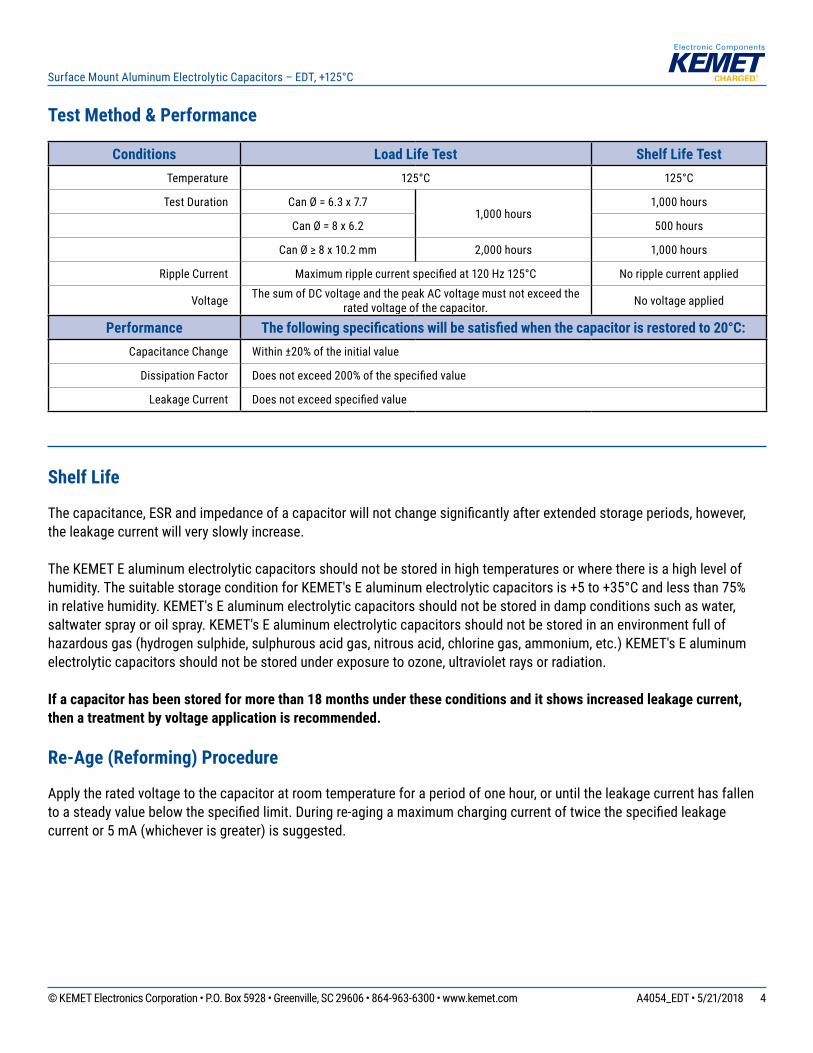
Test Method & Performance
Conditions Load Life Test Shelf Life TestTemperature 125°C 125°C
Test Duration Can Ø = 6.3 x 7.71,000hours
1,000hours
Can Ø = 8 x 6.2 500hours
CanØ≥8x10.2mm 2,000hours 1,000hours
Ripple Current Maximumripplecurrentspecifiedat120Hz125°C No ripple current applied
Voltage ThesumofDCvoltageandthepeakACvoltagemustnotexceedtheratedvoltageofthecapacitor. No voltage applied
Performance The following specifications will be satisfied when the capacitor is restored to 20°C:CapacitanceChange Within±20%oftheinitialvalue
Dissipation Factor Doesnotexceed200%ofthespecifiedvalue
Leakage Current Doesnotexceedspecifiedvalue
Shelf Life
Thecapacitance,ESRandimpedanceofacapacitorwillnotchangesignificantlyafterextendedstorageperiods,however,theleakagecurrentwillveryslowlyincrease.
TheKEMETEaluminumelectrolyticcapacitorsshouldnotbestoredinhightemperaturesorwherethereisahighlevelofhumidity.ThesuitablestorageconditionforKEMET'sEaluminumelectrolyticcapacitorsis+5to+35°Candlessthan75%inrelativehumidity.KEMET'sEaluminumelectrolyticcapacitorsshouldnotbestoredindampconditionssuchaswater,saltwatersprayoroilspray.KEMET'sEaluminumelectrolyticcapacitorsshouldnotbestoredinanenvironmentfullofhazardousgas(hydrogensulphide,sulphurousacidgas,nitrousacid,chlorinegas,ammonium,etc.)KEMET'sEaluminumelectrolyticcapacitorsshouldnotbestoredunderexposuretoozone,ultravioletraysorradiation.
If a capacitor has been stored for more than 18 months under these conditions and it shows increased leakage current, then a treatment by voltage application is recommended.
Re-Age (Reforming) Procedure
Applytheratedvoltagetothecapacitoratroomtemperatureforaperiodofonehour,oruntiltheleakagecurrenthasfallentoasteadyvaluebelowthespecifiedlimit.Duringre-agingamaximumchargingcurrentoftwicethespecifiedleakagecurrentor5mA(whicheverisgreater)issuggested.
Page 5
5© KEMET Electronics Corporation • P.O. Box 5928 • Greenville, SC 29606 • 864-963-6300 • www.kemet.com A4054_EDT • 5/21/2018
Surface Mount Aluminum Electrolytic Capacitors – EDT, +125°C
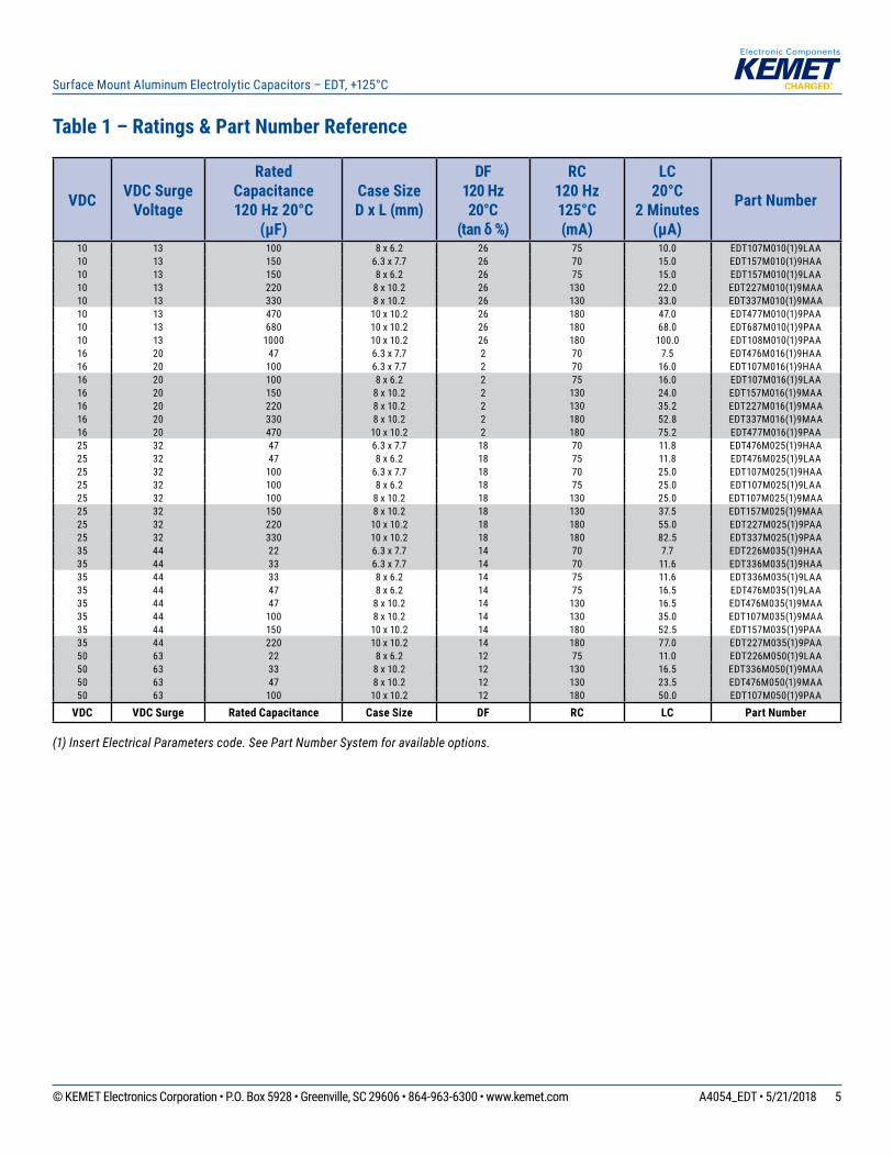
Table 1 – Ratings & Part Number Reference
(1) Insert Electrical Parameters code. See Part Number System for available options.
VDC VDC Surge Voltage
Rated Capacitance 120 Hz 20°C
(µF)
Case Size D x L (mm)
DF 120 Hz 20°C
(tan δ %)
RC 120 Hz 125°C (mA)
LC20°C
2 Minutes (µA)
Part Number
10 13 100 8 x 6.2 26 75 10.0 EDT107M010(1)9LAA10 13 150 6.3 x 7.7 26 70 15.0 EDT157M010(1)9HAA10 13 150 8 x 6.2 26 75 15.0 EDT157M010(1)9LAA10 13 220 8 x 10.2 26 130 22.0 EDT227M010(1)9MAA10 13 330 8 x 10.2 26 130 33.0 EDT337M010(1)9MAA10 13 470 10 x 10.2 26 180 47.0 EDT477M010(1)9PAA10 13 680 10 x 10.2 26 180 68.0 EDT687M010(1)9PAA10 13 1000 10 x 10.2 26 180 100.0 EDT108M010(1)9PAA16 20 47 6.3 x 7.7 2 70 7.5 EDT476M016(1)9HAA16 20 100 6.3 x 7.7 2 70 16.0 EDT107M016(1)9HAA16 20 100 8 x 6.2 2 75 16.0 EDT107M016(1)9LAA16 20 150 8 x 10.2 2 130 24.0 EDT157M016(1)9MAA16 20 220 8 x 10.2 2 130 35.2 EDT227M016(1)9MAA16 20 330 8 x 10.2 2 180 52.8 EDT337M016(1)9MAA16 20 470 10 x 10.2 2 180 75.2 EDT477M016(1)9PAA25 32 47 6.3 x 7.7 18 70 11.8 EDT476M025(1)9HAA25 32 47 8 x 6.2 18 75 11.8 EDT476M025(1)9LAA25 32 100 6.3 x 7.7 18 70 25.0 EDT107M025(1)9HAA25 32 100 8 x 6.2 18 75 25.0 EDT107M025(1)9LAA25 32 100 8 x 10.2 18 130 25.0 EDT107M025(1)9MAA25 32 150 8 x 10.2 18 130 37.5 EDT157M025(1)9MAA25 32 220 10 x 10.2 18 180 55.0 EDT227M025(1)9PAA25 32 330 10 x 10.2 18 180 82.5 EDT337M025(1)9PAA35 44 22 6.3 x 7.7 14 70 7.7 EDT226M035(1)9HAA35 44 33 6.3 x 7.7 14 70 11.6 EDT336M035(1)9HAA35 44 33 8 x 6.2 14 75 11.6 EDT336M035(1)9LAA35 44 47 8 x 6.2 14 75 16.5 EDT476M035(1)9LAA35 44 47 8 x 10.2 14 130 16.5 EDT476M035(1)9MAA35 44 100 8 x 10.2 14 130 35.0 EDT107M035(1)9MAA35 44 150 10 x 10.2 14 180 52.5 EDT157M035(1)9PAA35 44 220 10 x 10.2 14 180 77.0 EDT227M035(1)9PAA50 63 22 8 x 6.2 12 75 11.0 EDT226M050(1)9LAA50 63 33 8 x 10.2 12 130 16.5 EDT336M050(1)9MAA50 63 47 8 x 10.2 12 130 23.5 EDT476M050(1)9MAA50 63 100 10 x 10.2 12 180 50.0 EDT107M050(1)9PAA
VDC VDC Surge Rated Capacitance Case Size DF RC LC Part Number
Page 6
6© KEMET Electronics Corporation • P.O. Box 5928 • Greenville, SC 29606 • 864-963-6300 • www.kemet.com A4054_EDT • 5/21/2018
Surface Mount Aluminum Electrolytic Capacitors – EDT, +125°C
Mounting Positions (Safety Vent)
Inoperation,electrolyticcapacitorswillalwaysconductaleakagecurrentthatcauseselectrolysis.Theoxygenproducedbyelectrolysiswillregeneratethedielectriclayerbut,atthesametime,thehydrogenreleasedmaycausetheinternalpressureofthecapacitortoincrease.Theoverpressurevent(safetyvent)ensuresthatthegascanescapewhenthepressurereachesacertainvalue.Allmountingpositionsmustallowthesafetyventtoworkproperly.
Installing
• Ageneralprincipleisthatlower-usetemperaturesresultinalonger,usefullifeofthecapacitor.Forthisreason,itshouldbeensuredthatelectrolyticcapacitorsareplacedawayfromheat-emittingcomponents.Adequatespaceshouldbeallowedbetweencomponentsforcoolingairtocirculate,particularlywhenhighripplecurrentloadsareapplied.Inanycase,themaximumcategorytemperaturemustnotbeexceeded.
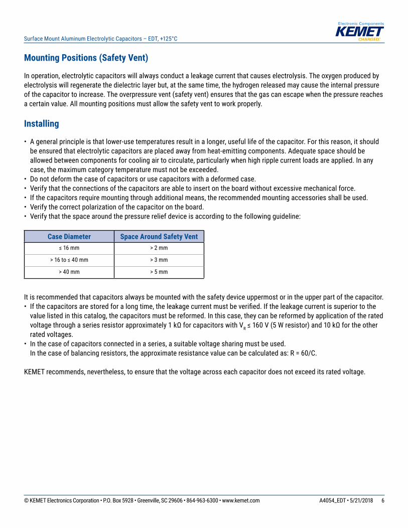
• Donotdeformthecaseofcapacitorsorusecapacitorswithadeformedcase.• Verifythattheconnectionsofthecapacitorsareabletoinsertontheboardwithoutexcessivemechanicalforce.• Ifthecapacitorsrequiremountingthroughadditionalmeans,therecommendedmountingaccessoriesshallbeused.• Verifythecorrectpolarizationofthecapacitorontheboard.• Verifythatthespacearoundthepressurereliefdeviceisaccordingtothefollowingguideline:
Case Diameter Space Around Safety Vent≤16mm > 2 mm
>16to≤40mm > 3 mm
> 40 mm > 5 mm
Itisrecommendedthatcapacitorsalwaysbemountedwiththesafetydeviceuppermostorintheupperpartofthecapacitor.• Ifthecapacitorsarestoredforalongtime,theleakagecurrentmustbeverified.Iftheleakagecurrentissuperiortothevaluelistedinthiscatalog,thecapacitorsmustbereformed.Inthiscase,theycanbereformedbyapplicationoftheratedvoltagethroughaseriesresistorapproximately1kΩforcapacitorswithVR≤160V(5Wresistor)and10kΩfortheotherrated voltages.
• Inthecaseofcapacitorsconnectedinaseries,asuitablevoltagesharingmustbeused.Inthecaseofbalancingresistors,theapproximateresistancevaluecanbecalculatedas:R=60/C.
KEMETrecommends,nevertheless,toensurethatthevoltageacrosseachcapacitordoesnotexceeditsratedvoltage.
Page 7
7© KEMET Electronics Corporation • P.O. Box 5928 • Greenville, SC 29606 • 864-963-6300 • www.kemet.com A4054_EDT • 5/21/2018
Surface Mount Aluminum Electrolytic Capacitors – EDT, +125°C
Application and Operation Guidelines
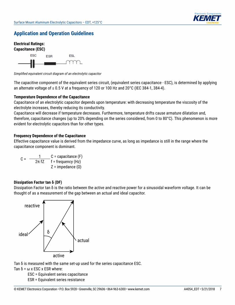
Electrical Ratings:Capacitance (ESC)
Simplifi ed equivalent circuit diagram of an electrolytic capacitor
Thecapacitivecomponentoftheequivalentseriescircuit,(equivalentseriescapacitance-ESC),isdeterminedbyapplyinganalternatevoltageof≤0.5Vatafrequencyof120or100Hzand20°C(IEC384-1,384-4).
Temperature Dependence of the CapacitanceCapacitanceofanelectrolyticcapacitordependsupontemperature:withdecreasingtemperaturetheviscosityoftheelectrolyteincreases,therebyreducingitsconductivity.Capacitancewilldecreaseiftemperaturedecreases.Furthermore,temperaturedriftscausearmaturedilatationand,therefore,capacitancechanges(upto20%dependingontheseriesconsidered,from0to80°C).Thisphenomenonismoreevidentforelectrolyticcapacitorsthanforothertypes.
Frequency Dependence of the Capacitance Effectivecapacitancevalueisderivedfromtheimpedancecurve,aslongasimpedanceisstillintherangewherethecapacitance component is dominant.
C = 1 C = capacitance (F)2πfZ f=frequency(Hz)
Z=impedance(Ω)
Dissipation Factor tan δ (DF)DissipationFactortanδistheratiobetweentheactiveandreactivepowerforasinusoidalwaveformvoltage.Itcanbethoughtofasameasurementofthegapbetweenanactualandidealcapacitor.
reactive
active
idealactual
δ
Tanδismeasuredwiththesameset-upusedfortheseriescapacitanceESC.Tanδ=ωxESCxESRwhere: ESC = Equivalent series capacitance ESR = Equivalent series resistance
Page 8
8© KEMET Electronics Corporation • P.O. Box 5928 • Greenville, SC 29606 • 864-963-6300 • www.kemet.com A4054_EDT • 5/21/2018
Surface Mount Aluminum Electrolytic Capacitors – EDT, +125°C
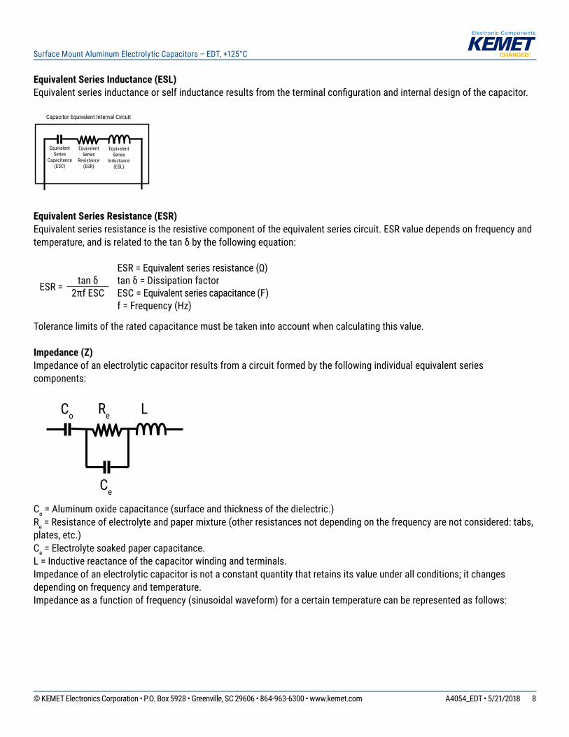
Equivalent Series Inductance (ESL)Equivalentseriesinductanceorselfinductanceresultsfromtheterminalconfigurationandinternaldesignofthecapacitor.
EquivalentSeries
Capacitance(ESC)
EquivalentSeries
Resistance(ESR)
EquivalentSeries
Inductance(ESL)
Capacitor Equivalent Internal Circuit
Equivalent Series Resistance (ESR) Equivalentseriesresistanceistheresistivecomponentoftheequivalentseriescircuit.ESRvaluedependsonfrequencyandtemperature,andisrelatedtothetanδbythefollowingequation:
ESR=Equivalentseriesresistance(Ω)
ESR = tanδ tanδ=Dissipationfactor2πfESC ESC = Equivalent series capacitance (F)
f=Frequency(Hz)
Tolerancelimitsoftheratedcapacitancemustbetakenintoaccountwhencalculatingthisvalue.
Impedance (Z)Impedanceofanelectrolyticcapacitorresultsfromacircuitformedbythefollowingindividualequivalentseriescomponents:
Equivalent
Capacitance
C o R e L
C e
Co Re L
Ce
Co=Aluminumoxidecapacitance(surfaceandthicknessofthedielectric.)Re=Resistanceofelectrolyteandpapermixture(otherresistancesnotdependingonthefrequencyarenotconsidered:tabs,plates, etc.)Ce=Electrolytesoakedpapercapacitance.L=Inductivereactanceofthecapacitorwindingandterminals.Impedanceofanelectrolyticcapacitorisnotaconstantquantitythatretainsitsvalueunderallconditions;itchangesdependingonfrequencyandtemperature.Impedanceasafunctionoffrequency(sinusoidalwaveform)foracertaintemperaturecanberepresentedasfollows:
Page 9
9© KEMET Electronics Corporation • P.O. Box 5928 • Greenville, SC 29606 • 864-963-6300 • www.kemet.com A4054_EDT • 5/21/2018
Surface Mount Aluminum Electrolytic Capacitors – EDT, +125°C
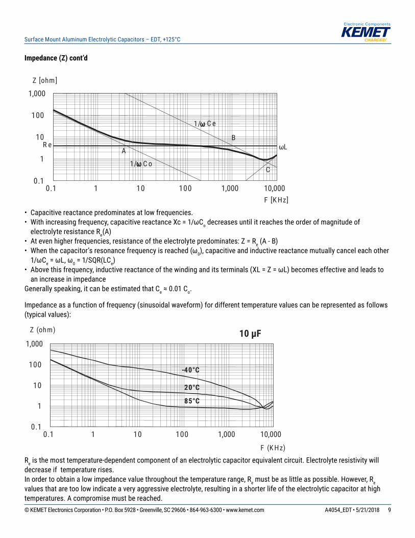
Impedance (Z) cont’d
�
C o R e L
C e
0.1 1 10 100 1,000 10,0000.1
1
10
100
1,000
Z [ohm ]
F [K Hz]
B
C
A
1/ωωωω C o
R e
1/ωωωω C e
ωL
• Capacitive reactance predominates at low frequencies.• Withincreasingfrequency,capacitivereactanceXc=1/ωCodecreasesuntilitreachestheorderofmagnitudeofelectrolyteresistanceRe(A)
• Atevenhigherfrequencies,resistanceoftheelectrolytepredominates:Z=Re (A - B)• Whenthecapacitor’sresonancefrequencyisreached(ω0),capacitiveandinductivereactancemutuallycanceleachother1/ωCe=ωL,ω0 = 1/SQR(LCe)
• Abovethisfrequency,inductivereactanceofthewindinganditsterminals(XL=Z=ωL)becomeseffectiveandleadstoan increase in impedance
Generallyspeaking,itcanbeestimatedthatCe≈0.01Co.
Impedanceasafunctionoffrequency(sinusoidalwaveform)fordifferenttemperaturevaluescanberepresentedasfollows(typicalvalues):
0.1 1 10 100 1,000 10,0000.1
1
10
100
1,000
Z (ohm)
F (K Hz)
85°C
20°C
10 µF
-40°C
Reisthemosttemperature-dependentcomponentofanelectrolyticcapacitorequivalentcircuit.Electrolyteresistivitywilldecrease if temperature rises.Inordertoobtainalowimpedancevaluethroughoutthetemperaturerange,Re must be as little as possible. However, Re valuesthataretoolowindicateaveryaggressiveelectrolyte,resultinginashorterlifeoftheelectrolyticcapacitorathightemperatures.Acompromisemustbereached.
Page 10
10© KEMET Electronics Corporation • P.O. Box 5928 • Greenville, SC 29606 • 864-963-6300 • www.kemet.com A4054_EDT • 5/21/2018
Surface Mount Aluminum Electrolytic Capacitors – EDT, +125°C
Leakage Current (LC)Duetothealuminumoxidelayerthatservesasadielectric,asmallcurrentwillcontinuetoflowevenafteraDCvoltagehasbeenappliedforlongperiods.Thiscurrentiscalledleakagecurrent.
Ahighleakagecurrentflowsafterapplyingvoltagetothecapacitorthendecreasesinafewminutes,forexample,afterprolongedstoragewithoutanyappliedvoltage.Inthecourseofcontinuousoperation,theleakagecurrentwilldecreaseandreachanalmostconstantvalue.
Afteravoltage-freestoragetheoxidelayermaydeteriorate,especiallyatahightemperature.Sincetherearenoleakagecurrentstotransportoxygenionstotheanode,theoxidelayerisnotregenerated.Theresultisthatahigherthannormalleakagecurrentwillflowwhenvoltageisappliedafterprolongedstorage.
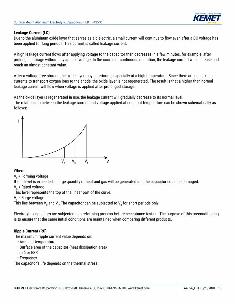
Astheoxidelayerisregeneratedinuse,theleakagecurrentwillgraduallydecreasetoitsnormallevel.Therelationshipbetweentheleakagecurrentandvoltageappliedatconstanttemperaturecanbeshownschematicallyasfollows:
I
VR VF VVS
Where:VF = Forming voltageIfthislevelisexceeded,alargequantityofheatandgaswillbegeneratedandthecapacitorcouldbedamaged.VR = Rated voltageThislevelrepresentsthetopofthelinearpartofthecurve.VS = Surge voltageThisliesbetweenVR and VF.ThecapacitorcanbesubjectedtoVSforshortperiodsonly.
Electrolyticcapacitorsaresubjectedtoareformingprocessbeforeacceptancetesting.Thepurposeofthispreconditioningistoensurethatthesameinitialconditionsaremaintainedwhencomparingdifferentproducts.
Ripple Current (RC)Themaximumripplecurrentvaluedependson: • Ambient temperature •Surfaceareaofthecapacitor(heatdissipationarea)tanδorESR
•FrequencyThecapacitor’slifedependsonthethermalstress.
Page 11
11© KEMET Electronics Corporation • P.O. Box 5928 • Greenville, SC 29606 • 864-963-6300 • www.kemet.com A4054_EDT • 5/21/2018
Surface Mount Aluminum Electrolytic Capacitors – EDT, +125°C
Frequency Dependence of the Ripple Current ESRand,thus,thetanδdependonthefrequencyoftheappliedvoltage.Thisindicatesthattheallowedripplecurrentisalsoafunctionofthefrequency.
Temperature Dependence of the Ripple CurrentThedatasheetspecifiesmaximumripplecurrentattheuppercategorytemperatureforeachcapacitor.
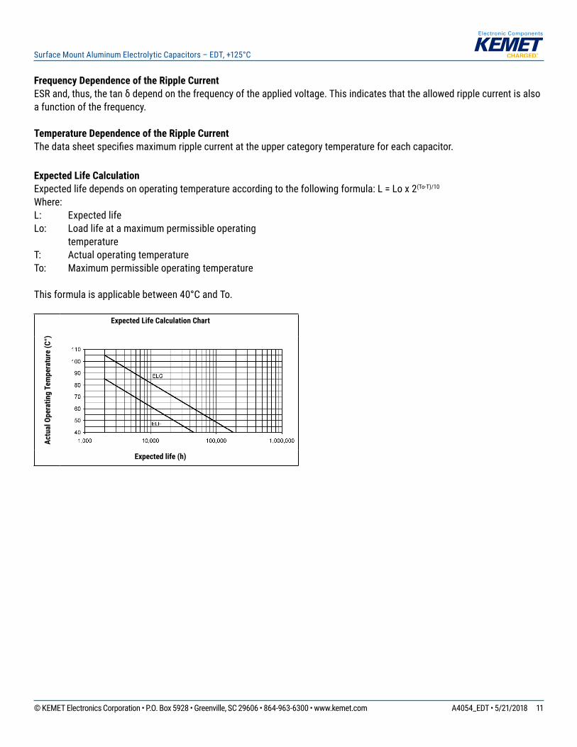
Expected Life CalculationExpectedlifedependsonoperatingtemperatureaccordingtothefollowingformula:L=Lox2(To-T)/10
Where:L: ExpectedlifeLo: Loadlifeatamaximumpermissibleoperating
temperatureT: ActualoperatingtemperatureTo: Maximumpermissibleoperatingtemperature
Thisformulaisapplicablebetween40°CandTo.
Actu
al O
pera
ting
Tem
pera
ture
(C°)
Expected Life Calculation Chart
Expected life (h)
Page 12
12© KEMET Electronics Corporation • P.O. Box 5928 • Greenville, SC 29606 • 864-963-6300 • www.kemet.com A4054_EDT • 5/21/2018
Surface Mount Aluminum Electrolytic Capacitors – EDT, +125°C
Packaging Quantities
Size Code Diameter (mm) Length (mm) Reel Quantity Box Quantity(4 Reels per box)
9H 6.3 7.7 1,000 10,0009L 8 6.2 1,000 10,0009M 8 10.2 500 4,0009P 10 10.2 500 4,000
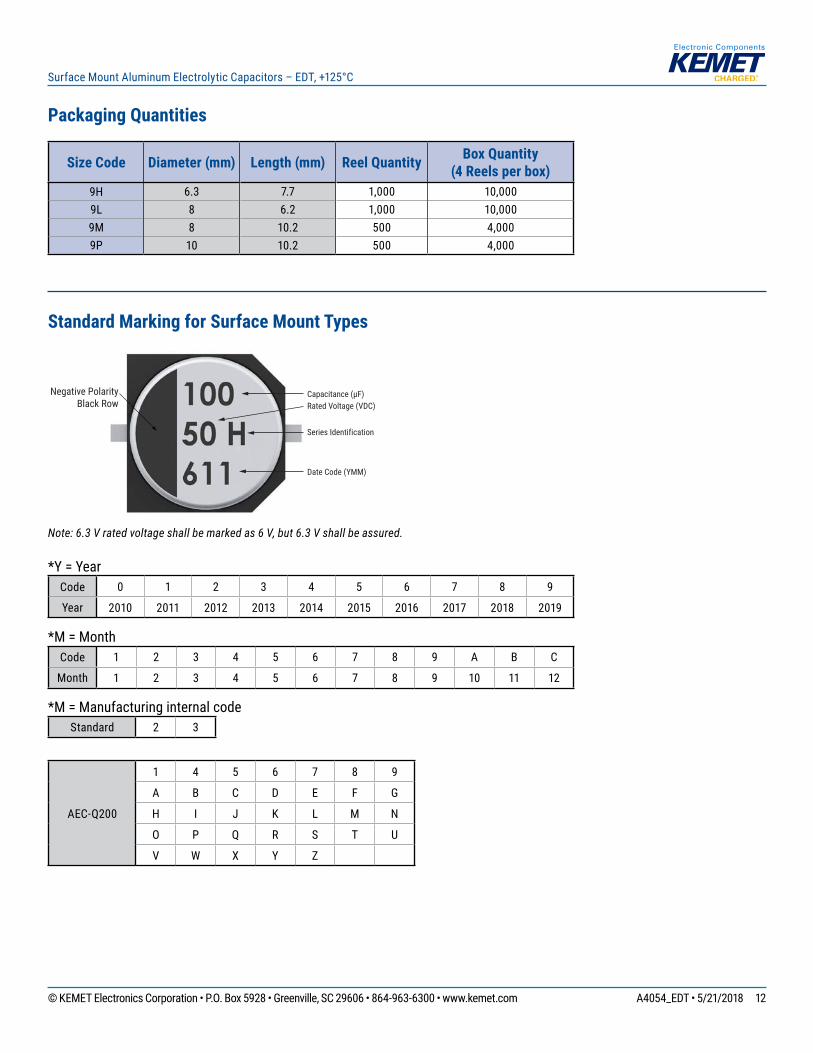
Standard Marking for Surface Mount Types
Negative PolarityBlack Row
Capacitance (µF)Rated Voltage (VDC)
Series Identification
Date Code (YMM)
Note: 6.3 V rated voltage shall be marked as 6 V, but 6.3 V shall be assured.
*Y = YearCode 0 1 2 3 4 5 6 7 8 9
Year 2010 2011 2012 2013 2014 2015 2016 2017 2018 2019
*M=MonthCode 1 2 3 4 5 6 7 8 9 A B C
Month 1 2 3 4 5 6 7 8 9 10 11 12
*M = Manufacturing internal codeStandard 2 3
AEC-Q200
1 4 5 6 7 8 9
A B C D E F G
H I J K L M N
O P Q R S T U
V W X Y Z
Page 13
13© KEMET Electronics Corporation • P.O. Box 5928 • Greenville, SC 29606 • 864-963-6300 • www.kemet.com A4054_EDT • 5/21/2018
Surface Mount Aluminum Electrolytic Capacitors – EDT, +125°C
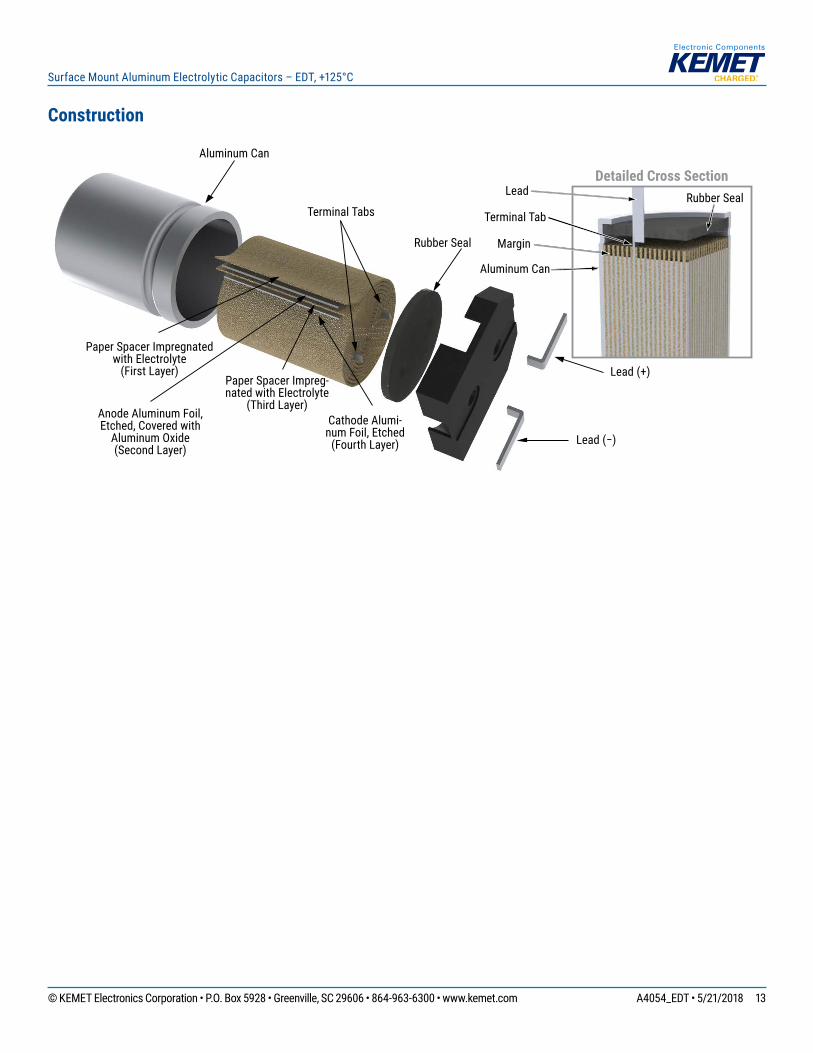
Construction
Detailed Cross Section
Margin
Rubber SealTerminal Tabs
Lead
Terminal Tab
Aluminum Can
Anode Aluminum Foil, Etched, Covered with
Aluminum Oxide (Second Layer)
Cathode Alumi-num Foil, Etched
(Fourth Layer)
Paper Spacer Impregnatedwith Electrolyte
(First Layer)Paper Spacer Impreg-nated with Electrolyte
(Third Layer)
Rubber Seal
Aluminum Can
Lead (+)
Lead (−)
Page 14
14© KEMET Electronics Corporation • P.O. Box 5928 • Greenville, SC 29606 • 864-963-6300 • www.kemet.com A4054_EDT • 5/21/2018
Surface Mount Aluminum Electrolytic Capacitors – EDT, +125°C
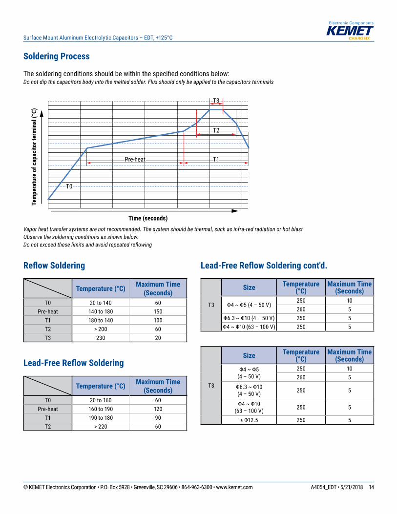
Soldering Process
Thesolderingconditionsshouldbewithinthespecifiedconditionsbelow:Do not dip the capacitors body into the melted solder. Flux should only be applied to the capacitors terminals
T1Pre-heat
T3T2
T3
T0
Time (seconds)
Tem
pera
ture
of c
apac
itor t
erm
inal
(°C)
Vapor heat transfer systems are not recommended. The system should be thermal, such as infra-red radiation or hot blastObserve the soldering conditions as shown below. Do not exceed these limits and avoid repeated reflowing
Reflow Soldering
Temperature (°C) Maximum Time (Seconds)
T0 20 to 140 60Pre-heat 140 to 180 150
T1 180 to 140 100T2 > 200 60T3 230 20
Lead-Free Reflow Soldering
Temperature (°C) Maximum Time (Seconds)
T0 20 to 160 60Pre-heat 160 to 190 120
T1 190 to 180 90T2 > 220 60
Lead-Free Reflow Soldering cont'd.
T3
Size Temperature (°C)
Maximum Time (Seconds)
Φ4~Φ5(4–50V)250 10260 5
Φ6.3~Φ10(4–50V) 250 5Φ4~Φ10(63–100V) 250 5
T3
Size Temperature (°C)
Maximum Time (Seconds)
Φ4~Φ5 (4–50V)
250 10260 5
Φ6.3~Φ10 (4–50V) 250 5
Φ4~Φ10 (63–100V) 250 5
≥Φ12.5 250 5
Page 15
15© KEMET Electronics Corporation • P.O. Box 5928 • Greenville, SC 29606 • 864-963-6300 • www.kemet.com A4054_EDT • 5/21/2018
Surface Mount Aluminum Electrolytic Capacitors – EDT, +125°C
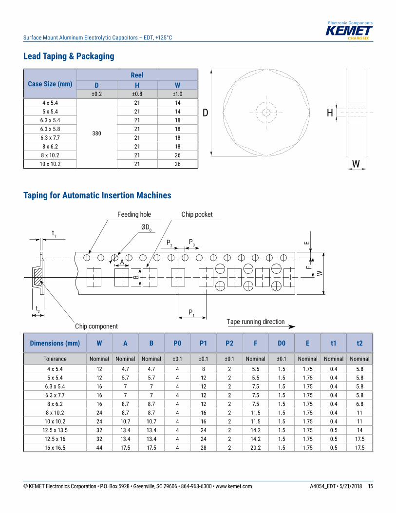
Lead Taping & Packaging
Case Size (mm)Reel
D H W±0.2 ±0.8 ±1.0
4 x 5.4
380
21 145 x 5.4 21 14
6.3 x 5.4 21 186.3 x 5.8 21 186.3 x 7.7 21 188 x 6.2 21 18
8 x 10.2 21 2610 x 10.2 21 26
Taping for Automatic Insertion Machines
Chip component Tape running direction
Chip pocketFeeding hole
t2
t1 P2
P0
A
B
P1
EF
W
ØD0
Dimensions (mm) W A B P0 P1 P2 F D0 E t1 t2
Tolerance Nominal Nominal Nominal ±0.1 ±0.1 ±0.1 Nominal ±0.1 Nominal Nominal Nominal
4 x 5.4 12 4.7 4.7 4 8 2 5.5 1.5 1.75 0.4 5.85 x 5.4 12 5.7 5.7 4 12 2 5.5 1.5 1.75 0.4 5.8
6.3 x 5.4 16 7 7 4 12 2 7.5 1.5 1.75 0.4 5.86.3 x 7.7 16 7 7 4 12 2 7.5 1.5 1.75 0.4 5.88 x 6.2 16 8.7 8.7 4 12 2 7.5 1.5 1.75 0.4 6.8
8 x 10.2 24 8.7 8.7 4 16 2 11.5 1.5 1.75 0.4 1110 x 10.2 24 10.7 10.7 4 16 2 11.5 1.5 1.75 0.4 11
12.5 x 13.5 32 13.4 13.4 4 24 2 14.2 1.5 1.75 0.5 1412.5 x 16 32 13.4 13.4 4 24 2 14.2 1.5 1.75 0.5 17.516 x 16.5 44 17.5 17.5 4 28 2 20.2 1.5 1.75 0.5 17.5
D
W
H
Page 16
16© KEMET Electronics Corporation • P.O. Box 5928 • Greenville, SC 29606 • 864-963-6300 • www.kemet.com A4054_EDT • 5/21/2018
Surface Mount Aluminum Electrolytic Capacitors – EDT, +125°C
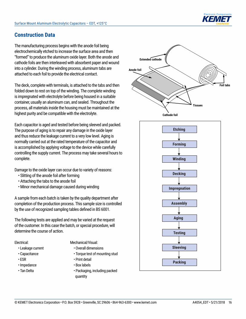
Extended cathode
Anode foil
Cathode foil
Tissues
Foil tabs
Aging
Etching
Forming
Winding
Decking
Impregnation
Assembly
Testing
Sleeving
Packing
Construction Data
Themanufacturingprocessbeginswiththeanodefoilbeingelectrochemicallyetchedtoincreasethesurfaceareaandthen“formed”toproducethealuminumoxidelayer.Boththeanodeandcathodefoilsaretheninterleavedwithabsorbentpaperandwoundintoacylinder.Duringthewindingprocess,aluminumtabsareattachedtoeachfoiltoprovidetheelectricalcontact.
Thedeck,completewithterminals,isattachedtothetabsandthenfoldeddowntorestontopofthewinding.Thecompletewindingisimpregnatedwithelectrolytebeforebeinghousedinasuitablecontainer,usuallyanaluminumcan,andsealed.Throughouttheprocess,allmaterialsinsidethehousingmustbemaintainedatthehighestpurityandbecompatiblewiththeelectrolyte.
Eachcapacitorisagedandtestedbeforebeingsleevedandpacked.Thepurposeofagingistorepairanydamageintheoxidelayerandthusreducetheleakagecurrenttoaverylowlevel.Agingisnormallycarriedoutattheratedtemperatureofthecapacitorandisaccomplishedbyapplyingvoltagetothedevicewhilecarefullycontrollingthesupplycurrent.Theprocessmaytakeseveralhourstocomplete.
Damagetotheoxidelayercanoccurduetovarietyofreasons: •Slittingoftheanodefoilafterforming •Attachingthetabstotheanodefoil •Minormechanicaldamagecausedduringwinding
Asamplefromeachbatchistakenbythequalitydepartmentaftercompletionoftheproductionprocess.ThissamplesizeiscontrolledbytheuseofrecognizedsamplingtablesdefinedinBS6001.
Thefollowingtestsareappliedandmaybevariedattherequestofthecustomer.Inthiscasethebatch,orspecialprocedure,willdeterminethecourseofaction.
Electrical: • Leakage current • Capacitance • ESR •Impedance • Tan Delta
Mechanical/Visual: • Overall dimensions • Torque test of mounting stud • Print detail • Box labels • Packaging, including packed
quantity
Page 17
17© KEMET Electronics Corporation • P.O. Box 5928 • Greenville, SC 29606 • 864-963-6300 • www.kemet.com A4054_EDT • 5/21/2018
Surface Mount Aluminum Electrolytic Capacitors – EDT, +125°C
KEMET Electronics Corporation Sales Offi ces
Foracompletelistofourglobalsalesoffices,pleasevisitwww.kemet.com/sales.
DisclaimerAllproductspecifications,statements,informationanddata(collectively,the“Information”)inthisdatasheetaresubjecttochange.ThecustomerisresponsibleforcheckingandverifyingtheextenttowhichtheInformationcontainedinthispublicationisapplicabletoanorderatthetimetheorderisplaced.
AllInformationgivenhereinisbelievedtobeaccurateandreliable,butitispresentedwithoutguarantee,warranty,orresponsibilityofanykind,expressedorimplied.
StatementsofsuitabilityforcertainapplicationsarebasedonKEMETElectronicsCorporation’s(“KEMET”)knowledgeoftypicaloperatingconditionsforsuchapplications,butarenotintendedtoconstitute–andKEMETspecificallydisclaims–anywarrantyconcerningsuitabilityforaspecificcustomerapplicationoruse.TheInformationisintendedforuseonlybycustomerswhohavetherequisiteexperienceandcapabilitytodeterminethecorrectproductsfortheirapplication.AnytechnicaladviceinferredfromthisInformationorotherwiseprovidedbyKEMETwithreferencetotheuseofKEMET’sproductsisgivengratis,andKEMETassumesnoobligationorliabilityfortheadvicegivenorresultsobtained.
AlthoughKEMETdesignsandmanufacturesitsproductstothemoststringentqualityandsafetystandards,giventhecurrentstateoftheart,isolatedcomponentfailuresmaystilloccur.Accordingly,customerapplicationswhichrequireahighdegreeofreliabilityorsafetyshouldemploysuitabledesignsorothersafeguards(suchasinstallationofprotectivecircuitryorredundancies)inordertoensurethatthefailureofanelectricalcomponentdoesnotresultinariskofpersonalinjuryorpropertydamage.
Althoughallproduct–relatedwarnings,cautionsandnotesmustbeobserved,thecustomershouldnotassumethatallsafetymeasuresareindictedorthatothermeasuresmaynotberequired.
KEMET is a registered trademark of KEMET Electronics Corporation.