Form Measurement Catalog No. E15004 Surface Roughness Measuring System SURFTEST SV-3100 Series Improve total throughput and perform highly accurate surface roughness measurement with best-in-class positioning speed and precision
Transcript
Form Measurement
Catalog No. E15004
Surface Roughness Measuring System
SURFTEST SV-3100 Series
Improve total throughput and perform highlyaccurate surface roughness measurement withbest-in-class positioning speed and precision
2
Powerful Support for Greater Efficiency inSurface Roughness Measurement!
Drive unit (X-axis): 80mm/s, column (Z2-axis): 20mm/sThe faster drive speed shortens the total measurement time.Auto-leveling table (option)Leveling is performed automatically even for complex measurement surfaces, dramatically reducing setting time.
Column (Z2-axis) incorporates an ABS (absolute origin) scaleImproved repeatability for operations such as continuous automatic measurement of small holes in the vertical direction or repetitive measurement of difficult-to-position parts.
Additional automation can be achieved using a Y-axis table and a rotary table (option)Automatic measurement of large numbers of parts one at a time or many parts at different locations on the worktable can be performed by attaching accessories such as a Y-axis table and a rotary table to dramatically reduce the manual workload.
Ceramic guidesTo ensure that the drive unit (X-axis) maintains its straightness for a long time, the tester uses ceramic guides that have excellent wear characteristics and minimal deformation over time. The use of ceramic also provides a maintenance-free design because lubrication with oil to prevent corrosion is not required.
Shorter measurement time
Eliminate human error
High durability
3
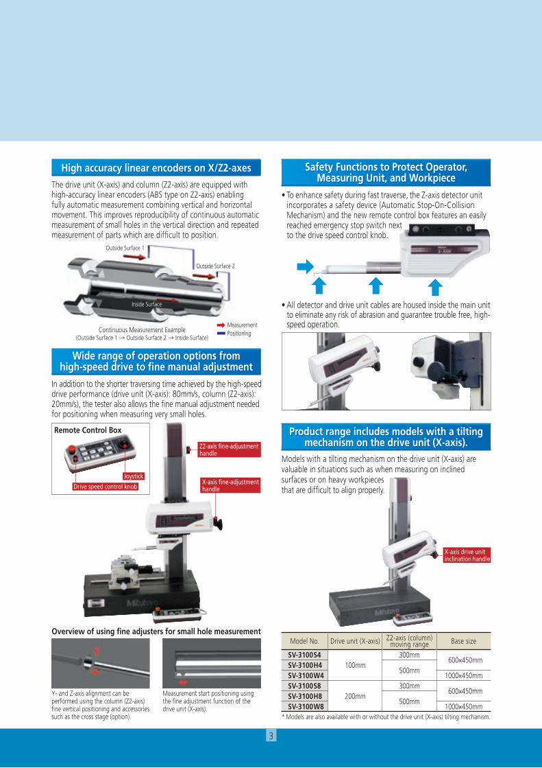
The drive unit (X-axis) and column (Z2-axis) are equipped with high-accuracy linear encoders (ABS type on Z2-axis) enabling fully automatic measurement combining vertical and horizontal movement. This improves reproducibility of continuous automatic measurement of small holes in the vertical direction and repeated measurement of parts which are difficult to position.
•Toenhancesafetyduringfasttraverse,theZ-axisdetectorunitincorporates a safety device (Automatic Stop-On-Collision Mechanism) and the new remote control box features an easily reached emergency stop switch next
Safety Functions to Protect Operator, Measuring Unit, and Workpiece
Models with a tilting mechanism on the drive unit (X-axis) are valuable in situations such as when measuring on inclined surfaces or on heavy workpieces that are difficult to align properly.
Product range includes models with a tilting mechanism on the drive unit (X-axis).
High accuracy linear encoders on X/Z2-axes
In addition to the shorter traversing time achieved by the high-speed driveperformance(driveunit(X-axis):80mm/s,column(Z2-axis):20mm/s),thetesteralsoallowsthefinemanualadjustmentneededfor positioning when measuring very small holes.
Wide range of operation options from high-speed drive to fine manual adjustment
Y- and Z-axis alignment can be performed using the column (Z2-axis) fine vertical positioning and accessories such as the cross stage (option).
Measurement start positioning using thefineadjustmentfunctionofthedrive unit (X-axis).
Overview of using fine adjusters for small hole measurement
Surface Roughness analysis function FORMTRACEPAKcanperformsurfaceroughnessanalysesthatconformtovariousstandardssuchasISO,JISANSI,andVDA.Forcomparingthemeasurementvalueswiththetolerancelimits,youcanusethe16%ruleorthemaximumvaluerule.Furthermore,sinceFORMTRACEPAKcomeswithparametercalculationfunctionsaswellasarichsetofgraphicanalysisfunctions, itcanbewidelyutilizedforeverythingfromroutinequalitycontroltoR&Dapplications.Italsoincludesmanyotherfunctions,suchasthefunctionforeliminating(compensating)shapes,suchasslopesandR-surface,andadatadeletionfunction.
Microscopic contour analysis function This function can calculate steps and surface areas from the roughness data.Furthermore,aswith thecontouranalysis function,a richsetofcalculation commands that combine variouselements,suchaspoints,lines,andcircles,tocalculateangles,pitches,and distances are provided as standard features.
Reference length dialog box
Multiple-point measurement function You can easily create a part program that measures multiple points by simply entering a shift.
Analysis function using multiple-point measurements
For a workpiece that cannot be measured over the evaluation distancespecifiedbyastandard,youcancalculatetheroughnessparameter fromthedataobtainedbymeasuringmultiplepoints,and compare the measurement data with the tolerance limits using the16%rule,forexample.
Analysis condition modification with a preview function You can easily modify various types of analysis conditions such as thestandardtobeused,curvetype,andfilter.Furthermore,beforeeliminating(compensating)shapessuchasslopes,R-surfaces,andparabolas,thepreviewfunctionallowsyoutochecktheimpactonthe spot.
R-surface automatic measurement function Basedonthepreliminarymeasurementresults,youcanautomaticallymeasure an R-surface by allocating measurement distances using the peak or bottom of the R-surface as the reference.
Peak Peak
Before compensation
After compensation
Simple input using drawing symbolsExample of drawing symbol
Grinding
Ra 1.5⊥ - 2.5/Rzmax 6.7
Example of entering dataU”X”0.08—0.8/Rz8max 3.3
You can easi ly set up cumbersome measurement condit ions by s imply entering data according to the drawing symbolsoftheISO/JISroughnessstandard.
When se t t i ng up the re fe rence l ength in a measurement condition,y o u c a n d i s p l a y t h e standard values defined by the ISO/JIS standardsby selecting the applicable standard.
5
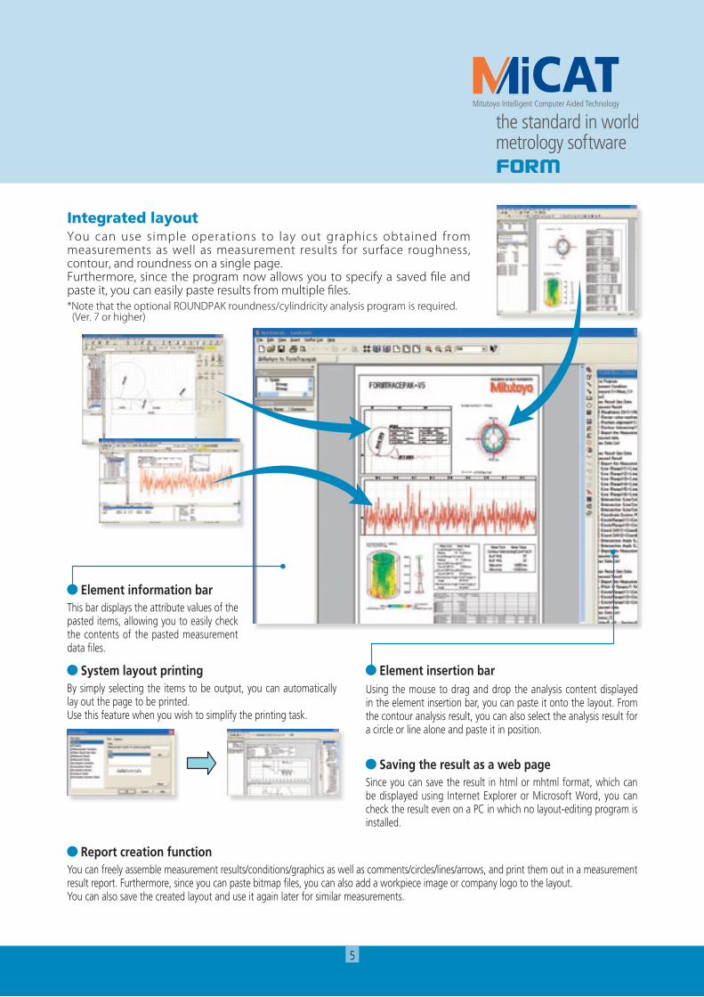
Integrated layout You can use simple operations to lay out graphics obtained from measurements as well as measurement results for surface roughness, contour, and roundness on a single page.Furthermore, since the program now allows you to specify a saved file and paste it, you can easily paste results from multiple files.*Note that the optional ROUNDPAK roundness/cylindricity analysis program is required. (Ver. 7 or higher)
Element information bar This bar displays the attribute values of the pasteditems,allowingyoutoeasilycheckthe contents of the pasted measurement data files.
System layout printing Bysimplyselectingthe itemstobeoutput,youcanautomaticallylay out the page to be printed.Use this feature when you wish to simplify the printing task.
Element insertion bar Using the mouse to drag and drop the analysis content displayed intheelementinsertionbar,youcanpasteitontothelayout.Fromthecontouranalysisresult,youcanalsoselecttheanalysisresultfora circle or line alone and paste it in position.
Saving the result as a web page Sinceyoucansavetheresult inhtmlormhtmlformat,whichcanbedisplayedusing InternetExplorerorMicrosoftWord,youcancheck the result even on a PC in which no layout-editing program is installed.
Report creation function Youcanfreelyassemblemeasurementresults/conditions/graphicsaswellascomments/circles/lines/arrows,andprintthemoutinameasurementresultreport.Furthermore,sinceyoucanpastebitmapfiles,youcanalsoaddaworkpieceimageorcompanylogotothelayout.You can also save the created layout and use it again later for similar measurements.
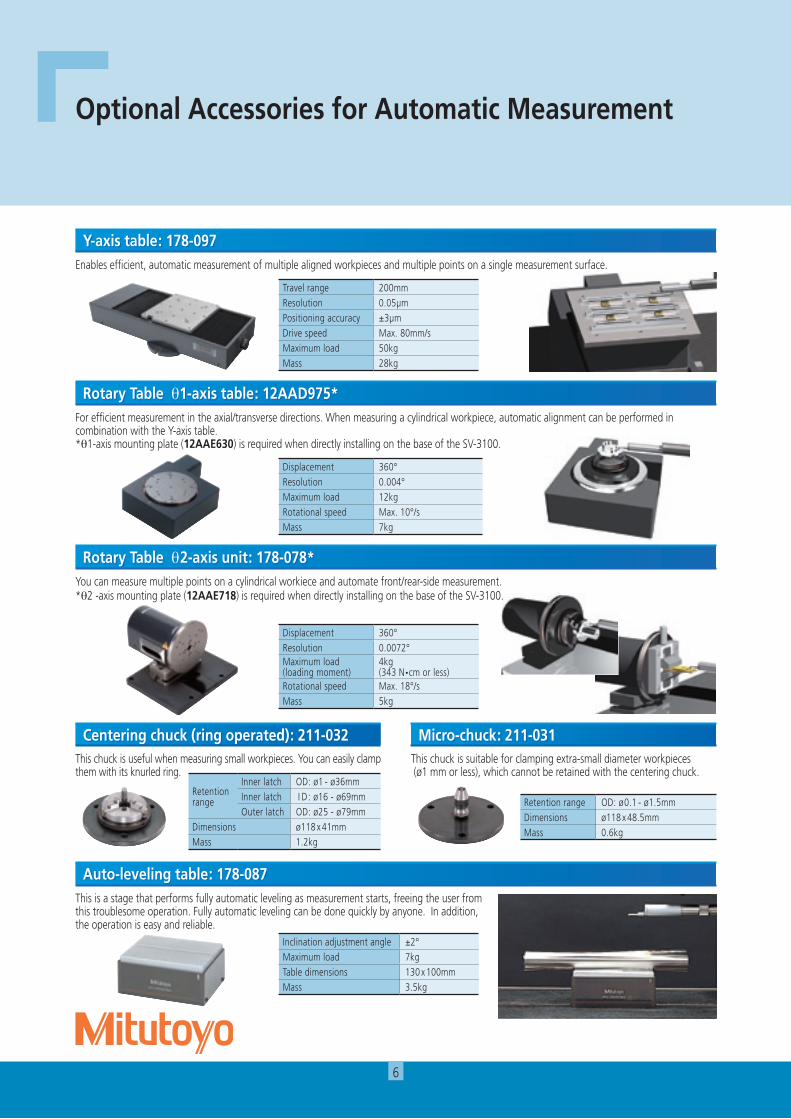
Forefficientmeasurementintheaxial/transversedirections.Whenmeasuringacylindricalworkpiece,automaticalignmentcanbeperformedincombination with the Y-axis table. *q1-axis mounting plate (12AAE630)isrequiredwhendirectlyinstallingonthebaseoftheSV-3100.
Thisisastagethatperformsfullyautomaticlevelingasmeasurementstarts,freeingtheuserfromthistroublesomeoperation.Fullyautomaticlevelingcanbedonequicklybyanyone.Inaddition,the operation is easy and reliable.
You can measure multiple points on a cylindrical workiece and automate front/rear-side measurement. *q2 -axis mounting plate (12AAE718)isrequiredwhendirectlyinstallingonthebaseoftheSV-3100.
This chuck is useful when measuring small workpieces. You can easily clamp them with its knurled ring.
This chuck is suitable for clamping extra-small diameter workpieces (ø1mmorless),whichcannotberetainedwiththecenteringchuck.
Retention range OD: ø0.1 - ø1.5mmDimensions ø118 x 48.5mmMass 0.6kg
7
Aligned Not aligned
Axial line
End point
Axial line
End point
Start pointStart point
Recorded profiles
Traverse directionTraverse direction
Thistablehelpsmakethealignmentadjustmentsrequiredwhenmeasuringcylindricalsurfaces.ThecorrectionsforthepitchangleandtheswivelanglearedeterminedfromapreliminarymeasurementandtheDigimaticmicrometersareadjustedaccordingly.Aflat-surfacedworkpiececanalsobeleveledwith this table.
Rotary vise218-003
V-block998291
Precision vise178-019
Cross-travel table218-001 (mm),218-011 (inch)
Cross-travel table218-041 (mm),218-051 (inch)
V-block with clamp172-234,172-378
Holder with clamp176-107
Swivel center support172-197
Center support riser172-143
Center support172-142
Leveling table178-043-1(mm),178-053-1 (inch)
Digital Leveling table178-042-1(mm),178-052-1 (inch)
Leveling table178-016
Leveling table (for D.A.T)178-016
Calibration stand12AAG175
Vibration isolator
3-axis Adjustment Table: 178-047
Others
Stand for Desktop typeExternal size(W×D×H): 640×470×660mmMass:25kgNo.178-024
Desktop type*1
No.178-023
Desktop type*1
No.178-025
Desk type*1
No.12AAK110
Monitor arm*2
No.12AAK120
Side table*2
No.12AAL019
*1: For models with a product code that ends in S4, S8, H4, or H8. Please contact us directly if you require units for models with a product code that ends in W4 or W8 (large base models).
*2: Used together with vibration isolator (No.12AAK110).*3: Please provide your own printer rack.
Example combination: with side table but no monitor arm (tester and PC not included)
Example combination: with monitor arm but no side table*3 (tester and PC not included)
172-378172-234
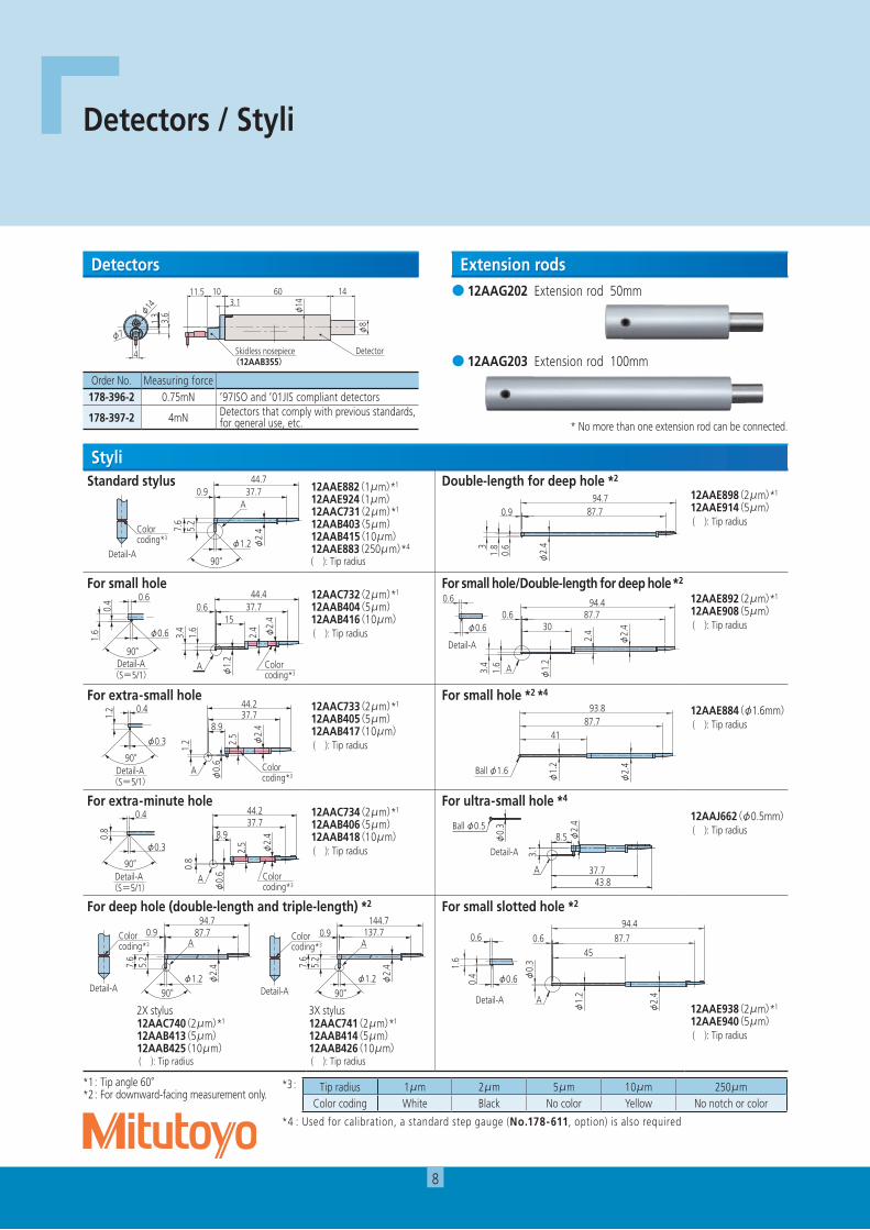
Standard stylus 12AAE882(1μm)*1
12AAE924(1μm)12AAC731(2μm)*1
12AAB403(5μm)12AAB415(10μm)12AAE883(250μm)*4
( ): Tip radius
Double-length for deep hole *2
12AAE898(2μm)*1
12AAE914(5μm)( ): Tip radius
For small hole12AAC732(2μm)*1
12AAB404(5μm)12AAB416(10μm)( ): Tip radius
For small hole/Double-length for deep hole *2
12AAE892(2μm)*1
12AAE908(5μm)( ): Tip radius
For extra-small hole12AAC733(2μm)*1
12AAB405(5μm)12AAB417(10μm)( ): Tip radius
For small hole *2 *4
12AAE884(φ1.6mm)( ): Tip radius
For extra-minute hole12AAC734(2μm)*1
12AAB406(5μm)12AAB418(10μm)( ): Tip radius
For ultra-small hole *4
12AAJ662(φ0.5mm)( ): Tip radius
For deep hole (double-length and triple-length) *2 For small slotted hole *2
12AAE938(2μm)*1
12AAE940(5μm)( ): Tip radius
2X stylus12AAC740(2μm)*1
12AAB413(5μm)12AAB425(10μm)( ): Tip radius
3X stylus12AAC741(2μm)*1
12AAB414(5μm)12AAB426(10μm)( ): Tip radius
*1: Tip angle 60° *2: For downward-facing measurement only.
8
Detectors / Styli
1460
φ8
φ14
Detector
φ14
φ7
1011.53.1
3.6
1.3
Skidless nosepiece(12AAB355)
4
● 12AAG202 Extension rod 50mm
● 12AAG203 Extension rod 100mm
* No more than one extension rod can be connected.
Detectors Extension rods
Styli
Order No. Measuring force178-396-2 0.75mN ’97ISO and ’01JIS compliant detectors
178-397-2 4mN Detectors that comply with previous standards, for general use, etc.
小穴用
Colorcoding*3
Detail-A
0.6
0.4
1.6 φ0.6
90°
(S=5/1)
φ2.
415
φ1.
2
3.4
2.4
1.6
0.6 37.744.4
A
極細穴用
Colorcoding*3
Detail-A
0.4
1.2
φ0.3
90°
(S=5/1)
φ2.
48.9
φ0.
6
2.5
37.7
1.2
44.2
A
超小穴用
Colorcoding*3
Detail-A
φ0.3
90°
0.8
0.4
(S=5/1)
φ2.
4
37.7
2.5
φ0.
6
8.9
44.2
0.8
A
深穴用
Colorcoding*3
Colorcoding*3
Detail-A Detail-A
φ2.
4
87.70.9
φ1.290°
94.7
7.6
5.2
A
φ2.
4
137.70.9
7.6
144.7
φ1.290°
5.2
A
深穴2倍用
31.
80.
6
φ2.
4
94.787.70.9
小穴用・深穴2倍
φ1.
2
1.6
3.4
2.4
φ2.
4
94.487.70.6
30
A
0.6
φ0.6
Detail-A
細穴形状用
φ1.
2
φ2.
4
Ball φ1.6
4187.7
93.8
極細穴形状用
φ2.
4φ0.
3
A
7
37.743.8
7
Ball φ0.5
Detail-A
φ2.
4
43.837.7
8.5
3.1
A
φ0.
3Ball φ0.5
Detail-A
細長穴用
φ0.
3
0.4
1.6
φ1.
2
φ2.
4
94.487.70.6
45
A
φ0.6
0.6
Detail-A
*3 : Tip radius 1μm 2μm 5μm 10μm 250μmColor coding White Black No color Yellow No notch or color
*4 : Used for calibration, a standard step gauge (No.178-611, option) is also required
標準スタイラス
90°
0.9 37.7
7.6
44.7
φ2.
4
φ1.2
5.2
A
Colorcoding*3
Detail-A
9
For deep groove (10mm)12AAC735(2μm)*1
12AAB409(5μm)12AAB421(10μm)( ): Tip radius
For deep groove *2 (20mm)12AAE893(2μm)*1
12AAE909(5μm)( ): Tip radius
For deep groove *2 (20mm) 12AAC736(2μm)*1
12AAB408(5μm)12AAB420(10μm)( ): Tip radius
For deep groove *2
(40mm) 12AAE895(2μm)*1
12AAE911(5μm)( ): Tip radius
For deep groove *2 (30mm) 12AAC737(2μm)*1
12AAB407(5μm)12AAB419(10μm)( ): Tip radius
For deep groove (30mm)/Double-length for deep hole *2
12AAE894(2μm)*1
12AAE910(5μm)( ): Tip radius
For gear tooth12AAB339(2μm)*1
12AAB410(5μm)12AAB422(10μm)( ): Tip radius
For gear tooth/Double-length for deep hole *2
12AAE896(2μm)*1
12AAE912(5μm)*1
( ): Tip radius
For rolling circle waviness surface *4
12AAB338(φ1.588)( ): Tip radius
For rolling circle waviness/Double-length for deep hole *2 *4
12AAE886(250μm)( ): Tip radius
For knife-edge 12AAC738(2μm)*1
12AAB411(5μm)12AAB423(10μm)( ): Tip radius
For corner hole/Double-length for deep hole *2
12AAE897(2μm)*1
12AAE913(5μm)*2
( ): Tip radius
For eccentric arm *2
12AAC739(2μm)*1
12AAB412(5μm)12AAB424(10μm)( ): Tip radius
For bottom surface12AAE899(2μm)*1
12AAE915(5μm)( ): Tip radius
*1: Tip angle 60° *2: For downward-facing measurement only.※Customized special interchageable styli are available on request, Please contact any Mitutoyo office for more information.
90°
13
φ2.
4
0.9
φ1.2
14.2
37.744.7
A
Colorcoding*3
Detail-A
深溝用(10mm)
23
0.9
φ2.
4
24.2
φ1.2
90°
37.744.7
A識別色
A部詳細
Colorcoding*3
Detail-A 90°
23 φ2.
4
φ1.2
24.2
37.744.7
A
深溝用(20mm)
33 31.8
5.2
φ1.2
A
φ2.4
φ2.
4
90°
37.745.2
Colorcoding*3
Detail-A
深溝用(30mm)
60°
60°
7.6
6.4
37.743.8
φ1.2 φ2.
4A
Colorcoding*3
Detail-A
歯面用
7.6
φ2.
4
φ1.2
0.9 37.744.7
Ball φ1.588
5.2
転がり円うねり用
7.6
φ2.
4φ1.290°
37.70.944.7
AColorcoding*3
Detail-A
ナイフエッジ用
A37.70.9
90°φ1.2
45.2
7.6
10
φ2.
4
φ2.
4
識別色
A部詳細
Colorcoding*3
Detail-A
心違い用
90° φ2.
4φ1.2
45.21.4 37.7
7.6φ
2.410
A
Styli
*3 : Tip radius 2μm 5μm 10μmColor coding Black No color Yellow
*4 : Used for calibration, a standard step gauge (No.178-611, option) is also required
23 21.8 5.2
95.2
87.7
φ2.4
φ1.2
深溝用2倍(20mm)
43.8
42.6
5.2
φ2.
4
45.237.7
φ2.4
φ1.2
深溝用(40mm)
36.5
35
5.2
φ3
93.887.7
φ1.2
深溝用(30mm)深穴2倍
36.5
35
φ3
93.8
6.77
87.7
φ1.2
60°
歯面用深穴2倍
94.70.9 87.7
φ1.2 φ2.
4
5.2
6.4
7.6
転がり円うねり・深穴2倍
93.887.7
35
φ0.8
45°
5.8 5 φ1.
6
φ2.
4
穴測定コーナー用・深穴2倍
穴底用
7.4 φ
1
0.5
56.2
φ2.
4
44.337.7
10
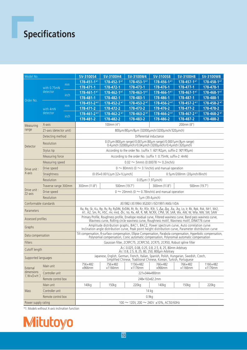
Specifications
Model No. SV-3100S4 SV-3100H4 SV-3100W4 SV-3100S8 SV-3100H8 SV-3100W8
Data compensation Tiltcompensation,R-surfacecompensation,EllipseCompensation,Parabolacompensation,Hyperboliccompensation,Polynomialcompensation,Conicautomaticcompensation,Polynomialautomaticcompensation
Supported languages Japanese,English,German,French,Italian,Spanish,Polish,Hungarian,Swedish,Czech,SimplifiedChinese,TraditionalChinese,Korean,Turkish,Portuguese
Externaldimensions( W×D×H)
Main unit 756×482×966mm
756×482×1166mm
1156×482×1176mm
766×482×966mm
766×482×1166mm
1166×482×1176mm
Controller unit 221×344×490mm
Remote control box 248×102×62.2mm
Mass
Main unit 140kg 150kg 220kg 140kg 150kg 220kg
Controller unit 14 kg
Remote control box 0.9kg
Power supply rating 100~ 120V, 200~ 240V±10%,AC50/60Hz
Note: All information regarding our products, and in particular the illustrations, drawings, dimensional and performance data contained in this pamphlet, as well as other technical data are to be regarded as approximate average values. We therefore reserve the right to make changes to the corresponding designs, dimensions and weights. The stated standards, similar technical regulations, descriptions and illustrations of the products were valid at the time of printing. Only quotations submitted by ourselves may be regarded as definitive.Our products are classified as regulated items under Japanese Foreign Exchange and Foreign Trade Law. Please consult us in advance if you wish to export our products to any other country. If the purchased product is exported, even though it is not a regulated item (Catch-All controls item), the customer service available for that product may be affected. If you have any questions, please consult your local Mitutoyo sales office.
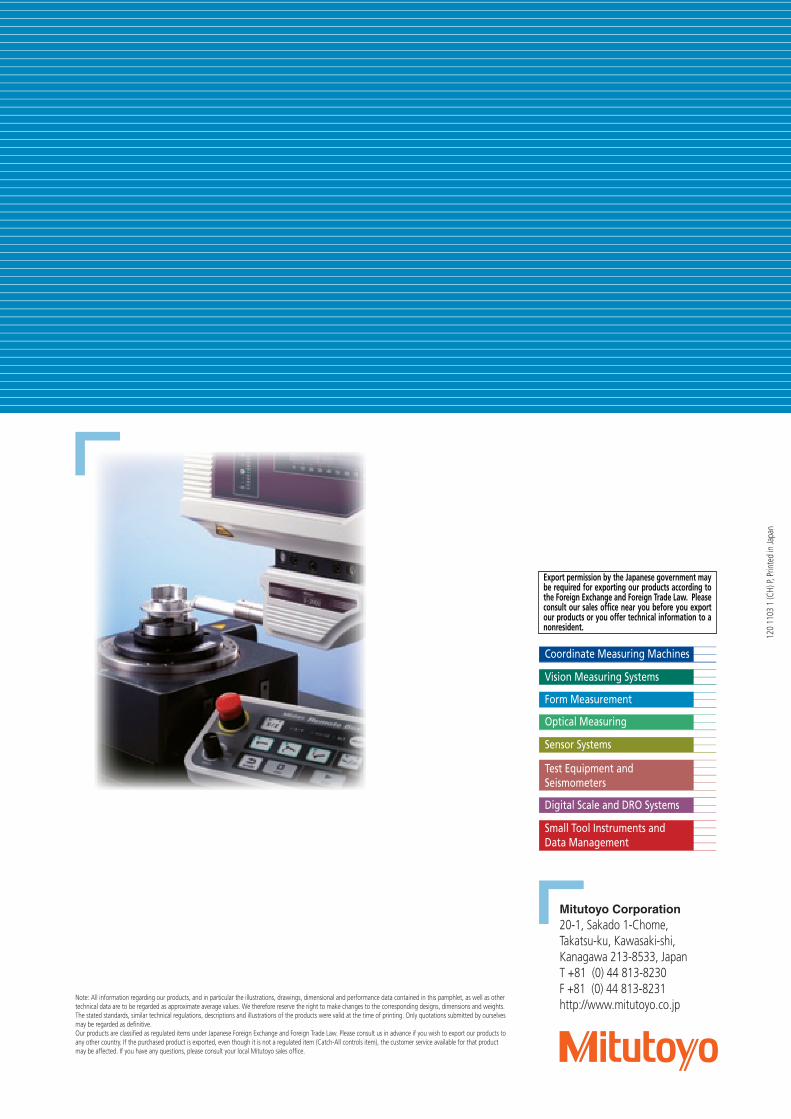
Export permission by the Japanese government may be required for exporting our products according to the Foreign Exchange and Foreign Trade Law. Please consult our sales office near you before you export our products or you offer technical information to a nonresident.