SURFACTANT-ENHANCED ALKALINE FLOODING FOR LIGHT OIL RECOVERY Contract No. DE-AC22-92BC14883 Illinois Institute of Technology Chicago, IL Contract Date: Sept. 1991 Anticipated Completion: Sept. 1995 Goverment Award: $150,000 (Current year) Principal Investigator: Darsh T. Wasan Technical Project Officer: Jerry F. Casteel Banlesville Project Office Reporting Period: July 1 - September 30, 1995 DISCLAIMER This report was prepared as an account of work sponsored by an agency of the United States Government. Neither the United States Government nor any agency thereof, nor any of their employees, makes any warranty, express or implied, or assumes any Iegd liability or responsi- bility for the accuracy, completeness, or usefulness of any information, apparatus, product, or process disclosed, or represents that its use would not infringe privately owned rights. Refer- ence herein to any specific commercial ptoduct, process, or service by trade name, trademark, manufacturer, or otherwise does not necessarily constitute or imply its endorsement, recom- mendation, or favoring by the United States Government or any agency thereof. The views and opinions of authors expressed herein do not necessarily state or reflect those of the United States Government or any agency thereof. ~ -~ __ _ _ ~ -~ ~ - ~ __ ~ -~
Transcript
SURFACTANT-ENHANCED ALKALINE FLOODING FOR LIGHT OIL RECOVERY
Technical Project Officer: Jerry F. Casteel Banlesville Project Office
Reporting Period: July 1 - September 30, 1995
DISCLAIMER
This report was prepared as an account of work sponsored by an agency of the United States Government. Neither the United States Government nor any agency thereof, nor any of their employees, makes any warranty, express or implied, or assumes any Iegd liability or responsi- bility for the accuracy, completeness, or usefulness of any information, apparatus, product, or process disclosed, or represents that its use would not infringe privately owned rights. Refer- ence herein to any specific commercial ptoduct, process, or service by trade name, trademark, manufacturer, or otherwise does not necessarily constitute or imply its endorsement, recom- mendation, or favoring by the United States Government or any agency thereof. The views and opinions of authors expressed herein do not necessarily state or reflect those of the United States Government or any agency thereof.
~ -~ _ _ _ _ ~ -~ ~ - ~ _ _ ~ -~
SURFACTANT-ENHANCED ALKALINE FLOODING FOR LIGHT OIL RECOVERY
Quarterly Report for the Period July 1 -September 30, 1995
BY Darsh T. Wasan ’
Work Performed Under Contract No. DE-AC22-92BC14883
Document Control Center U.S. Department of Energy
Pittsburgh Energy Technology Center
Pittsburgh, PA 15236-0940 P.O. BOX 10940, MS 921-118
Prepared by Illinois Institute of Technology
10 West 33rd St. Chicago, IL 60616
1
OBJECTIVE The overall objective of this project is to develop a very cost-effective method for
formulating a successful surfactant-enhanced alkaline flood by appropriately choosing mixed
alkalis which form inexpensive buffers to obtain the desired pH (between 8.5 and 12.0) for
ultimate spontaneous emulsification and ultra-low tension. In addition, the novel concept of pH
gradient design to optimize flood water conditions will be tested.
SUMMARY OF TECHNICAL PROGRESS The problem of characterizing emulsions in porous media is very important in enhanced
oil recovery applications. This is usually accomplished by externally added or insitu generated
surfactants that sweep the oil out of the reservoir. Emulsification of the trapped oil is one of the
mechanisms of recovery. The ability to detect emulsions in the porous medium is therefore
crucial to designing profitable flood systems. The capability of microwave dielectric techniques
to detect emulsions in porous medium is demonstrated by mathematical modelling and by
experiments. This quarter the shape dependence of the complex dielecmc properties of W/O and O/W
type dispersions in the microwave frequency region were analyzed using the generalized effective
medium theory of Hanai. The computations show that our earlier finding for spherical dispersions can now be extended to include nonspherical geometries. The computed results show
that the difference in dielectric behavior of the two emulsion types are a strong function of the
shape of the dispersions, with the differences vanishing when the two phases are oriented as
layers parallel and perpendicular to the electromagnetic field.
RESULTS AND DISCUSSION Fricke (1924) has developed a more general solution following Maxwell for the effective
dielectric constants of dilute dispersions containing ellipsoidal particles. For ellipsoids with axes
a,b, and c the depolarization factor (shape factor), L along a-axis is given by elliptical integrals
and are functions of the semiprincipal axis (a, b, and c) of the ellipsoids.
Solutions are obtained in closed form only when the particles are spheroids, Le., b=c. For the case of spheres, a=b=c, all three L terms assume the value of 1/3. For a prolate spheroid,
2
1 (1)
- L, = LabcJrds/(s +a 2, [ (s +a 2, (s +b 2, (s + c 2)A]
2
For oblate spheroids a<<b=c
Hanai’s expression for the dielectric constant for spheres can be easily generalized to obtain
where el is the dispersed phase dielectric constant, + the dispersed phase volume fraction,
the continuous phase dielectric constant and E, the effective dielectric constant of the dispersion.
For spheres, L=1/3 and Equation 4 simplifies to the original Hanai expression for spheres. For
flat discs with their faces parallel to the field or for needles with their axes parallel to the field,
L is zero and we obtain
The dielectric constant is identical to that of layers of oil and water (with thicknesses smaller
than the wavelength) for the case in which the field is parallel to the interface. Similarly for
disks with field impressed normal to the face, L=l and the equation reduces to
These results are identical to those obtained by Sen et. al. (1981) based on their model for
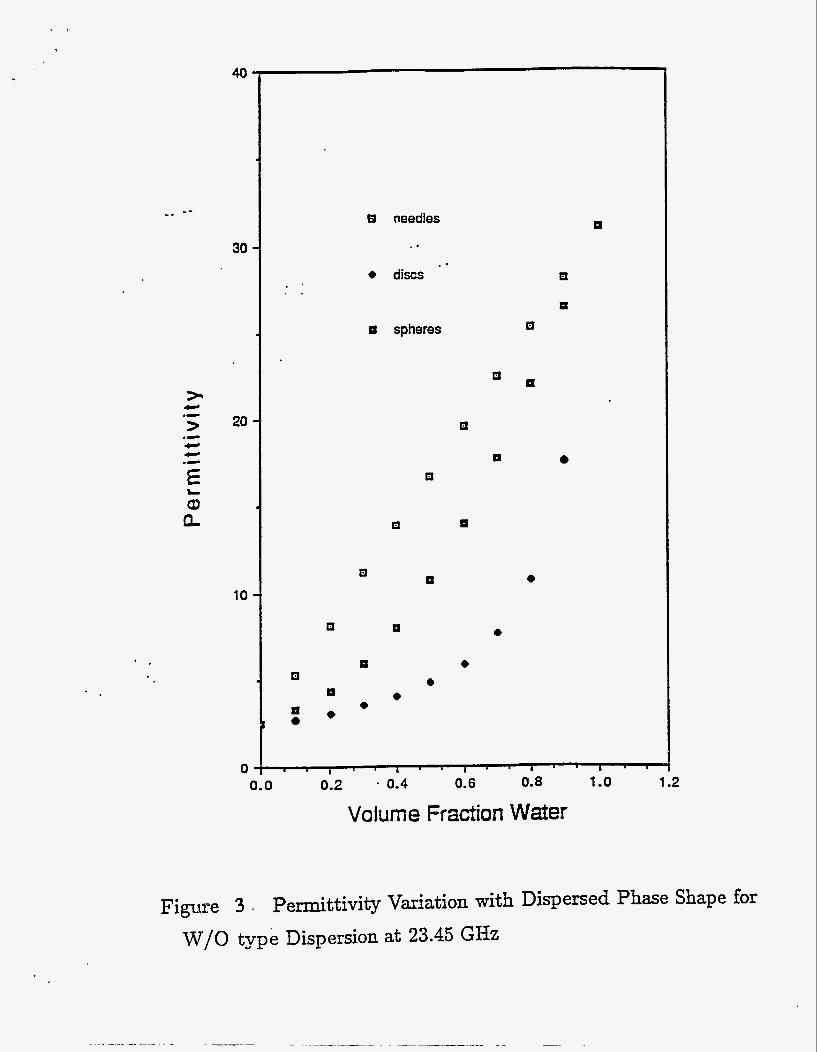
heterogeneous media .with self similar geometry. The simulated results for the dielectric
properties for spheres (L=1/3), needles (La), and plates (L=l) are shown in Figures 1, 2, and
3
3. The computed results are for a W/O type dispersion at 23.45 GHz. The permittivity and
loss factor of the plate shaped dispersions are much lower than the corresponding needle-like
dispersions. The results indicate that for nonsphencal dispersions, the shape of the dispersion and its orientation to the electric field has a significant effect on dispersion dielectric properties.
REFERENCES
1. Fricke H., A Mathematical Treatment of the Electrical Conductivity and Capacity of
Dispersed Systems", Phys. Rev., 24, 575 (1924). Sen, P.N., Scala, C., and Cohen, M.H., "A Self-similar Model for Sedimentary Rocks
with Applications to the Dielectric Constant of Fused Glass Beads", GeoPhysics, 46,781
(1981).
2.
PUBLICATIONS
1. Nikolov, A. and Wasan, D.T.,"Effects of Surfactant on Mutiple Stepwise Coalescence of
Single Drops at Liquid-Liquid Interfaces", I&EC Research, 34, 3653 (1995).
40
30
20
10
0
a needles
t discs . .
LI spheres
a
B
a
a
E
a
I
U
0.0 0.2 0.4 0.6 0.8 1 .o 1.2
Volume Fraction Water
Figure 1 Loss Tangent Variation with Dispersed Phase Shape for W/O type Dispersion at 23.45 GHz
12
1 .o
_ - _.
0.8
L
0 0 cu
L L
cn cn 0 J
c
0.6
0.4
0.2 ’ .
0.0
P
P
P
a 0 a
U
E
0
0
n needles
0 discs
0
* ’
0.0 0.2 0.4 0.6 0.8
Voiurne Fraction Water 1 .o 1.2
Figure 2 Loss Factor Variation with Dispersed Phase Shape for W/O type Dispersion at 23.45 GHz
- - -. B needles
30 .. ..
4 discs n
E spheres
> L .- 20
CI
E L a a9 Q LI
Q n 4 10
Q n 4
n 4 e
4 II
4 4 LI
0 0.2 . 0.4 0.6 0.8 1 .o 1.2
Volume Fraction Water 0.0
Figure 3 , Permittivity Variation with Dispersed Phase Shape for W/O type Dispersion at 23.45 GHz