ENGINEERING MONOGRAPHS No. 17 United States Department of the Interior BUREAU OF RECLAMATION SURGE CONTROL ON THE COACHELLA PIPE DISTRIBUTION SYSTEM By C. S. Hale, P. W. Terrell, R. E. Glover, and W. P. Simmons, Jr. Denver, Colorado January 1954 40 cents
Transcript
ENGINEERING MONOGRAPHS No. 17
United States Department of the InteriorBUREAU OF RECLAMATION
SURGE CONTROL ON THE COACHELLA
PIPE DISTRIBUTION SYSTEM
By C. S. Hale, P. W. Terrell,
R. E. Glover, and W. P. Simmons, Jr.
Denver, Colorado
January 1954
40 cents
United States Department of the Interior
DOUGLAS McKAY, Secretary
Bureau of Reclamation
W. A. DEXHEIMER, CommissionerL, N. McCLELLAN, Assistant Commissioner and Chief Engineer
Engineering Monograph
No. 17
SURGE CONTROL ON THE COACHELLA
PIPE DISTRIBUTION SYSTEM
By
C. S. Hale, Construction Engineer, Coachella Division;P. W. Terrell, R. E. Glover, and W. P. SImmons, Jr.,Office of the Assistant Commissioner and Chief Engineer
Technical Information OfficeDenver Federal Center
Denver, Colorado
ENGINEERING MONOGRAPHS are publishedin limited editions for the technical staff of theBureau of Reclamation and interested technicalcircles in government and private agencies.Their purpose is to record developments, inno-vations, and progress in the engineering andscientific techniques and practices that are em-ployed in the planning, design, construction, andoperation of Reclamation structures and equip-ment. Copies may be obtained from the Bureauof Reclamation, Denver Federal Center, Denver,Colorado, and Washington, D. C.
........................Baffle Adjustment 8.........................Pipe Line Vents 8
.......................Gates in the Baffles 9...............Control Gates in Outlet Pipe Entrances 9
.......................Siphons in the Baffles 10.................Overflow Pipes in Lieu of Baffles 10
....................Studies of Air Entrainment 12..............Effect of Additional Water Surface Area 12
.............USE OF AIR-TIGHT COVERS ON PIPE STANDS 13
......................Development of Covers 13............Test of Temporary Air-Tight Covers in Field 14
................Permanent Air-Tight Covers in Field 14.......Analytical Investigations of System with Covered Stands 17
...........................Notation 17...........The single reach of pipe between box stands 19
..................The period of a single reach 21.................Effect of covered pipe stands 22
.......Electric Analog Studies of Systems with Covered Stands 24...................Description of the analog 24
.....................Low frequency analog 27...........Operating results with low frequency analog 27
......................Computed periods 28
......................Resonance spectra 28...................Checks and correlations 31
...............Computation of resonance factors 31...........................Example 32
............DIVISION OF WORK AND ACKNOWLEDGMENTS 33
I
LIST OF FIGURES
Number Page
1 Pipe stand overflowing as a result of surging ........ ...
1
2 Coachella Valley County Water District Generalplan and plat of Unit 6
................. ...
2
3 Flow conditions in pipe stands
.............. ...
3
4 Overall view of headbox and stands 1, 2, and 3in the laboratory model ................. ...
6
5 The large air bubble and entrained air in thepipeline ........................ ...
7
6 Flume with wall and outlet pipe in place .......... ...
12
7 Permanent precast concrete cover for pipe stands
..... ...
15
8 Permanent precast concrete cover for box stands
..... ...
16
9 The single reach of pipe between two stands
........ ...
18
10 Resonance factors .................... ...
19
11 System with two pipe reaches--common standcovered ........................ ...
20
12 System with three pipe reaches--two pipe standscovered ........................ ...
24
13 Analogous electrical circuit for system with threepipe reaches--two pipe stands covered .......... ...
25
14 Resonance spectra for system with single pipe reachand for system with two pipe reaches--commonstand covered
..................... ...
28
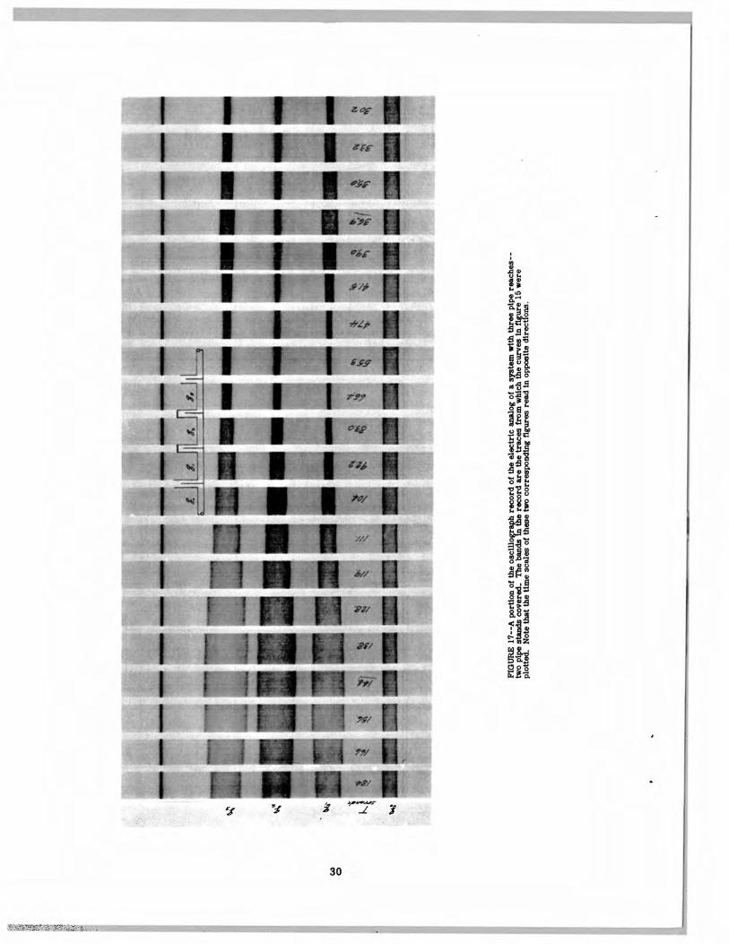
15 Resonance spectra for system with three pipereaches--two stands covered
.............. ...
29
16 Resonance spectra for system with four pipereaches- -three stands covered
............. ...
29
17 Oscillograph record of electric analog of fourpipe stands--two stands covered 30
11
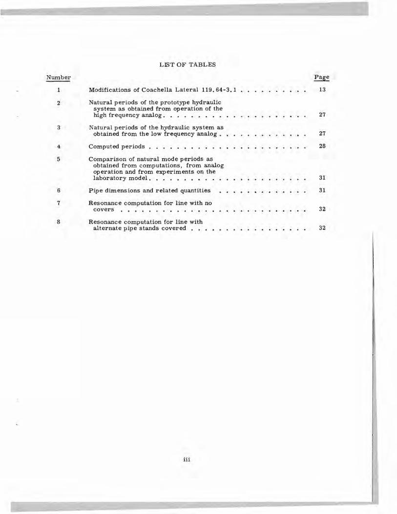
LIST OF TABLES
Number Page
1 Modifications of Coachella Lateral 119. 64-3. 1
..... .....
13
2 Natural periods of the prototype hydraulicsystem as obtained from operation of thehigh frequency analog ................ .....
27
3 Natural periods of the hydraulic system asobtained from the low frequency analog ........ .....
27
4 Computed periods
.................. .....
28
5 Comparison of natural mode periods asobtained from computations, from analogoperation and from experiments on thelaboratory model .................. .....
31
6 Pipe dimensions and related quantities
........ .....
31
7 Resonance computation for line with nocovers
...................... .....
32
8 Resonance computation for line withalternate pipe stands covered
............ .....
32
i-il
INTRODUCTION
In 1947 the Bureau of Reclamation under-took the construction of a pipe distributionsystem to carry water from the CoachellaBranch of the All-American Canal to about100, 000 acres of land in the Coachella Valley.When the system was put into operation inMarch 1950, however, some of the lateralscould not be operated satisfactorily becauseof severe surging (a rythmical Increase anddecrease in the flow past a given point) whichcaused extreme head variations at the farmturnouts in portions of the system. This con-dition not only wasted water and made properirrigation difficult, but in some cases deliv-eries were Insufficient for irrigation needs.
Analytical and field Investigations of thesurging were begun almost immediately.Later a model of part of a typical field lat-eral was built in the Bureau's Denver lab-oratories. These analytical, field, and lab-oratory studies led to the installation of air-tight covers on the open pipe stands at eachfarm turnout, and these effectively controlledthe surging. This monograph describes thestudies that led to this solution, and givesmethods by which similar systems may bedesigned to keep surging at a minimum.
DESCRIPTION OF IRRIGATION SYSTEM
Figure 2 shows the location of the Coa-chella Valley In southern California. Theground slopes from an elevation of 524 feet atthe north downward to the Salton Sea, 240 feetbelow sea level. The temperature seldomfalls below freezing, and crops are grownthroughout the year. Rainfall averages about3 inches per year, making Irrigation neces-sary for agriculture.
Preliminary studies indicated that a low-pressure pipe system would be slightly morecostly to build than an open-canal system butwould permit higher delivery gradients withsmaller seepage and evaporation losses andhence lower operating costs, and would entailless right-of-way encroachment through ciii-tivated areas. Further studies Indicated thata low-pressure pipe system would be mate-rially less expensive to construct than a high-pressure system,, and it was decided to con-struct the former. For construction purposesthe system was divided into nine units (see
figure 2). FIgure 2 also shows the generalplan for Unit 6, with the quantities of flow,the points of delivery, and the number anddesignation of the laterals.
The laterals are located along sectionand mid-section lines. Quarter-mile sub-laterals are provided to serve adjoining lands,with a farm turnout to each 40 acres of land.,or one and sometimes two turnouts at eac hquarter-mile of lateral. Open-topped box rpipe stands were constructed at each turnc,utpoint to maintain a low internal head on t;hepipe lines. The top of the stand was mad.e 2feet higher than the maximum operating 'wa-ter surface. A baffle or partition in the s tandserves as a check at low flows to provid€ thehead required for turnout deliveries (figure3). Excess flows at a given turnout pass overthis baffle Into the downstream half of thestand, then flow through the outgoing pipeline to the next stand. This design divideseach lateral into a series of elongated U-tubes, with the upper leg formed by thedownstream side of one stand and the lowerleg formed by the upstream side of the nextstand. Turnouts from the laterals are con-trolled by gate or disk-type valves built in-tegrally with a propeller-type meter.
CAUSE OF SURGING
Surging appears to be initiated by anyone or all of a number of factors. Thesemay include auto-oscil]ations of small amp-
iJ
V
-
-
FIGURE 1--PIpe stand overflowing a.s a resultul surging.
rN e
be!
,n.
Err COn$tructrm put
the d.str,ct ne a,
O,Sbt,pt
+KEY
IAP
L!
'.
COACHELLA VALLEY COUNTY WATER OSTRICTGENERAL PLAN
$AN oIKao
cALT0M
SEA
o \\\
UNIT No.6(TYPICAL)
FIGURE 2--Coachella Valley County Water District. General plan and plat of Unit 6.
2
FIGURE 3--Flow conditions in pipe stands.
litude, caused by entrapment and release ofair, imposed oscillations from outside sourcessuch as by wind blowing across the tops ofopen pipe stands and by disturbances to flowcaused by making or cutting off deliveries.Other sources probably exist. The abilityof the system to amplify these initiating os-cillations under certain conditions may thenbuild them into surges of large magnitudein reaches further downstream.
The storage and release of entrapped airwas found to be a source of initiating oscilla-tions in certain pipe reaches. Water fallingover the baffle in a pipe stand entrains a massof air bubbles as it plunges into the water pooion the downstream side of the baffle. Thesebubbles penetrate the pool to considerabledepths and a portion of them are carried intothe pipe with the flowing water. After enter-ing the pipe they float to the top and collectin a long bubble against the top of the pipe.Since the pipe has a gradient In the directionof flow and the bubble floats, there Is a forcetending to move the bubble upstream. As thebubble grows in volume, the buoyancy finallyovercomes the drag of the water, the bubblemoves upstream, and part of it discharges intothe pipe stand. The volume of air released isthen replaced by water having the velocityof the water In the pipe reach. In this wayan Increment of kinetic energy is fed Into the
system to initiate a succession of water leveland velocity changes in the reach. Observa-tions indicate that the blowback tends to occurin that part of the cycle which will permitenergy to be fed into the oscillation. Theend result is that bubble formation and de-struction falls into step with the oscillationsand supplies the energy necessary to main-tain them.
The amplitude of these oscillations orsurges is ordinarily not large and would beof only minor significance if another factorwere not involved. The trouble experiencedin the field occurs where a pipe line has beenbuilt down section lines for several miles withpipe stands at regular intervals. This equalspacing of stands and the gently sloping ter-rain provide a succession o pipe reacheswith nearly identical natural periods. Underthese culitions a small auto-oscillation orig-inating in an upstream reach can be amplifiedinto a surge of detrimental proportions insuccessive reaches.
GLOSSARY
Some of the terms used in this monographhave their origin in vibration theory. Thisglossary defines these terms and explainstheir connection with surging in pipe lines.
a. A vibrating system is created whenone or more masses are subject to con-straints which tend to return them to anequilibrium position or to fix the positionof each with relation to the others. In apipe distribution system the masses arethe water in the pipe reaches and the con-straints are the forces which tend to bringthe levels in the pipe stand back to stablerunning levels.
b. The term degree of freedom is usefulin classifying vibrating systems. The de-grees of freedom of a vibrating system arethe minimum number of quantities neededto describe the motions of the system. Apipe reach between open pipe stands is aone degree of freedom system because onlyone quantity is needed to describe its mo-tion. This quantity can be either the de-parture from the normal running level inthe downstream half of the upstream pipestand or the departure from the mean ye-locity of the flow in the pipe reach. A sys-tem comprising two pipe reaches with thecommon pipe stand capped is a two degreeof freedom system because two departuresfrom normal level or two departures frommean velocity are needed to describe itsmotions. This system differs dynami-cal ly from two reaches with an open standbetween them because the air pressurechanges under the cap make the effect ofmovements in the lower reach felt uponthe upper reach and the two reaches canno longer act independently. A systemhaving one or more capped stands in suc-cession has as many degrees of freedomas there are pipe reaches in the system.Such a system is a portion of the pipe line.It begins and ends at an open pipe stand buthas all of the interior pipe stands capped.
c. A mode of vibration is simply themanner in which a vibration is executed.A natural mode is one which a vibratingsystem can execute without change of pat-tern if it is forcibly displaced from itsequilibrium position, in a manner con-forming to the pattern, and released. Thenumber of natural modes of a vibrating sys -tern is equal to the number of degrees offreedom of the system.
d. Each natural mode has its own asso-ciated natural period.
e. The gravest mode or fundamentalmode is the mode having the longest nat-ural period. A vibrating system sub-jected to a sinusoidal disturbing force willexecute a forced mode of vibration. Thisforced mode will have the same period asthe disturbing force.
f. If the sinusoidal disturbing force hasa period corresponding to a natural modeperiod the mode having this period will be -come predominant and the amplitude of vi-bration will tend to grow to a high level.This is called resonance.
g. The conditions producing resonancewould tend to build up the amplitude of vi-bration without limit were it not for thepresence of damping forces, which set alimit to the amplitudes which can be at-tained.
h. The amount of damping just suffi-cient to prevent oscillatory motion whenthe system is displaced from its equilib-rium position and released is called crit-ical daniping. With this or greater amountsof damping, amplification by resonancecannot occur.
i. If the damping is small compared tothe critical damping so that the system canosciliate freely in any of its natural modes,then amplification by resonance will alvaysoccur if the sinusoidal disturbing force hasa period longer than the natural period ofthe system. If the disturbing force has theshorter period then amplification by reso-nance will occur until the ratio of the peri-ods reaches about 1.4. Beyond this pointsuppression occurs.
SUMMARY AND CONCLUSIONS
Surging originates in small oscillationswhich may be due to a variety of causes,among which are air entrapment and releaseand the disturbances incident to making de-liveries. These small oscillations have aperiod which is the same as the natural pe-riod of the reach in which they originate. Inan orderly system, such as the one in theCoachella Valley, resonance occurs and givesrise to amplification. Any small surge isthereby amplified in each succeeding reachuntil it grows to an unmanageable magnitude.The solutions found for this trouble accorn -
plish their purpose by either consuming theenergy of the oscillation or by destroying thepossibility of resonance.
General
Two factors must be present in a pipeline to cause surging. These factors are aninitiating oscillation and the amplificationtendency. Sources of an initiating oscillationappear to be always present. The two mostpotent are small oscillations driven by en-trainment and release of air in the pipe line,and disturbance incident to making deliveries.However, field observations indicate thepresence of other sources.
In an open system comprising a pipe linewith baffled pipe stands at intervals, eachpipe reach connected to a pipe stand at bothends has a natural period of oscillation. Thisperiod is a function of the pipe length and di-ameter and the water-surface area in thedownstream half of the pipe stand at the upperend of the reach. If the natural periods ofsuccessive reaches are nearly alike, ampli-fication will occur. Thus if a flow oscillationhaving a period near to the natural periods ofthe reaches is fed mb the upper end of theline, each reach will discharge at its lowerend a flow having a variation of greater am-plitude than that fed into it at its upper end.
The amount of amplification is influencedby the frictional losses in the reach, which inturn depend on the amount of flow in the line.If the frictional loss is low, the amplificationmay be large. If the frictional forces arelarge, amplification may not occur. Thussurging is Likely to be greatest at flows whichare small compared to full capacity flow, andin pipe lines with gradients low enough topermit the pipe to remain full at no flow.
No devices have been found which willprevent air entrainment in pipe stands witha straight baffle. However, a round verticaloverflow riser located in the center of a cir-cular pipe stand is effective in reducing airentrainment. A pipe line with pipe stands ofthis kind will, however, amplify small surgesof the proper period fed into it or createdwithin the lateral.
Surge Control Devices
Gates.- -Gates in the baffles or outlet pipeare an effective means of surge suppression,
if adjusted so that no water spills over thebaffle. However, a pipe line equipped withgates is cumbersome to operate.
Control of surface areas, - -A pipe linecan be stabilized by selecting pipe-stand sizesor adding additional water-surface area inopen pipe stands to throw the various ele-ments of the line out of synchronism. Themost effective arrangement found is one inwhich the periods increase downstream, withsuccessive pipe reaches having a ratio of nat-ural periods of the order of 1.4 or more. Ifthe line is long, such a solution adds greatlyto the cost of the system.
Air vents. --Field experience with airvents has shown them to be ineffective as ameans of surge control.
Covers. --Airtight covers on pipe standscontrol surging effectively and economicallyin systems with gradients low enough to per-mit the pipe lines to run full at low flows.A pressure relief valve and a device to re-lieve excessive negative pressures shouldbe provided. (Since airtight covers exerttheir control through pressure changes inthe air trapped under them, surging in pipereaches laid on slopes so steep that they donot run l'ull at low flows cannot be effectivelycontrolled by covers because the air volumetrapped under the cover is too great to beeffective.)
Airtight covers produce their effect firstby grouping the original pipe reaches intosystems which have oscillation periods dif-ferent from tlxse of the original pipe reaches,thereby throwing the reaches out of synchro-nism; second by reducing the number of sys-tems capable of resonance; and third by cre-ating systems which do not oscillate as freelyas the orginal reaches.
The application of airtight covers to anumber of pipe stands in succession createsa system which behaves dynamically as aunit. This system comprises all the pipereaches joined to the pipe stands, togetherwith the downstream half of the open pipestand at the upstream end of the first pipereach and the upstream half of the pipe standat the lower end of the last pipe reach.
Each system created by airtight covershas a number of natural modes of oscillation
equal to the number of pipe reaches in thesystem. Each of these modes has an asso-ciated natural period for which resonancecan occur. In general, resonance in thehigher modes is so weak that they are of nopractical significance; the mode having thelongest period, or gravest mode, is of im-portance. Resonance in this mode is gen-era Uy weaker than that of the individual pipereaches of the system before application ofthe covers.
The period of the gravest mode of a sys-tem created by the use of n airtight coversin sue cession is approximately
'Li L2
+4n^l)\A(n+l)I
When the pipe reaches are all alike this re-duces to
= 27(n + 1) F1L1A1g
This formula holds for a single reach withopen stands at both ends if n is set equalto zero.
In these expressions, L1 ... L(n + 1)represents the lengths of the successive pipereaches in the system, A1 ... A( + 1) rep-resent the corresponding cross sectionalareas, F1 represents the area of the hori-zontal cross section of the downstream halfof the pipe stand at the upper end of the sys-tem, g represents the acceleration of grav-ity, and iT= 3.14159. Iftheqtantities LlLn are expressed In feet, Fl and AlA(n + 1) in square feet and g In ft/sec2 theperiod T will be given in seconds.
The performance of a pipe line with sin-gle reaches and systems created by usingairtight covers can be investigated by com-puting the period of each and working throughthe system on the assumption that an air-driven auto-oscillation can occur in the grav-est mode of any reach, or system, and com-puting an over-all resonance factor for thatpart of the line downstream from the reachor system in which the oscillation is assumedto originate. The system may be considered
satisfactory if none of the over-all resonancefactors thus computed exceeds about 20.
The most favorable arrangement is onein which the gravest mode periods increaseprogressively downstream, If some featuresof a given line make the application of thisrule awkward, then it is permissible tochoose an alternative pattern, since the num-ber of covers used on a pipe line is more Im-portant than the pattern in which they are in-stalled. The resonance. possibilities shouldbe checked, however, in the manner de-scribed above.
THE LABORATORY MODEL
The laboratory test set-up was con-structed to represent a typical section of theopen-stand-type distribution lateral used atCoacheila and at a number of other projects,although it represented no particular struc-ture on any project. It consisted of a watersupply system, a head box, three verticalpipe stands 20 inches in diameter, each divi-ded into two equal vertical sections by a baf-fle, three 8-inch by 125-foot pipe lines con-necting the stands in series, and an 8-inchreturn line (figure 4). Because of space lim-itations and for convenience in operation andview ing, the model was arranged with thehead box and the stands side by side and withthe pipe lines extended about 60 feet down-stream, then turned back to enter the next
FIGURE 4--Overall view of headbox and stands1, 2, and 3 In the laboratory model.
FIGURE 5--The large air bubble andentrained air in the swirling flow withinthe pipeline immediately downstreamfrom headbox stand. Q - 0.37 cfs.
stand. The first 16 feet of the first line wassloped 1 inch in 16 feet to represent a typicalprototype slope and the first 6 feet of thissection was made of transparent plastic topermit observ ations of the flow inside the line.The rest of this Line and the two other lineswere sloped to provide a total drop of 3 feeteach.
Water was supplied to the model by an8-Inch supply line which contained a standard,calibrated, laboratory orifice venturi meterfor measuring the rate of flow. The waterentered the upstream portion of the head boxthrough an 8-inch pipe, then passed througha rock baffle which removed the major flowturbulences. Immediately downstream fromthe baffle was a motor-operated, verticallyreciprocating float to be used, when desired,to produce uniform depth variations in thehead box. (These forced surges or oscilla-tions should not be confused with seLf-inducedor auto-oscillations.) After passing the rockbaffle and float the water moved to the down-stream end of the box and over a rectangularbaffle 20 inches wide, and entered the equiva-lent of the downstream half of a stand. Fromthis half-stand the water entered the pipe lineto flow to stand 1, where it filled the upstreamhalf of the stand, passed over the baffle, andfilled the downstream half of the stand suf-ficiently to produce flow in the pipe. Fromthere it passed through stands 2 and 3 andthen back to the main supply channel for re-circulation.
The baffles were made of 1/8-inch sheetsteel. Higher baffle elevations were obtained
by placing extensions upon these base baffles.Sheet-metal slide gates 8 inches in diameterwere placed in the base of the baffles at theelevation of the outlet pipe to permit studyingthe effect of gates for surge control. Win-dows near the bottom in the downstream sec-tion of the stands permitted observation ofthe water inside the stand and at the entranceof the outlet pipe.
The amplitude of the surges in the standswas msured by suitable point gages on port-able bases atop the stands. The amplitude aswell as the period of successive surges variedgreatly and it was necessary to take repeatedreadings at the high and low points of the in-dividual surges to obtain a representativeaverage surge measurement. Thus, unlessotherwise qualified, all results are given asaverages.
It was not definitely known beforehandthat the model would auto-oscillate like thefield structure, but self-induced surging wasnoted in the model as soon as water waspassed through it, even though the water wasentering the head box at a constant rate. Thesurging was greatest at 0. 37 cfs and dimin-
ished when the flow was either increased ordecreased. Large quantities of air werecarried into the pool in the downstream sec -tion of the pipe line (figure 5). The small bub-bles collected in a large bubble in the top ofthe pipe which periodically became suffi-ciently buoyant that it moved upstream in thesloping pipe and part of it vented in the pipestand. This cycle was in phase with the surg-
ing, as explained in the section on auto-oscil-lation.
ducing baffle crest heights for low flows andconstructing deflecting baffles above the pipestand outlet to determine the effect of vary-ing the flow condition over the baffle and ofregulating the point of impact of the fallingwater. None of the devices was effective.
A second baffle was constructed about6 inches downstream from the existing bafflein two consecutive pipe stands. An openingwas placed near the bottom of the second baf-fle to eliminate the direct fall over the baf-fle. This device, too, was ineffective.
Pipe Line Vents
Model studies. - -The periodic build-upof the long air bubble in the outlet pipe andits venting into the stand suggested that ifthe pipe line were vented by other means theair could no longer cause surging. A ver-tical pipe one inch in diameter was placedin the plastic portion of the first pipe line.When the vent was opened, air escaped force-fully and slugs of water were thrown severalfeet into the air. While the surge into stand 1and hence into stands 2 and 3 was consider-ably reduced by opening this vent, the smallsurge present was amplified.
The partial success of the vent in theplastic pipe indicated that vents betweenstands 1 and 2 and stands 2 and 3 would stopmost of the residual surging. Vents wereput into these outlet pipes by inserting,through the stand, "Li' shaped tubes madeof two sections of 1-inch pipe and a 90° elifitting. The horizontal section of the ventpipe extended downstream along the top ofthe pipe into the air bubble. Although therewas a continual discharge of air and the oc-casional violent explusion of water from thesevents, they had only a slight effect upon thesurging. When the first vent was closed butthe other two vents were left open, the aver-age surge in stand 3 was about the same aswithout vents. The effect of the vents wasto reduce the part the air plays in creatingthe surges, but had no effect in suppressingthe amplification of the residual surge in thesystem. If a surge is present due to anycause, the pipe line vents will not preventthe amplification of this surge through thesystem. It was conclnded that pipe line ventsare impractical for prototype surge control.
Prototype studies. - -Various combina-tions of controls on the baffle overflow were
Prototype studies. --The CoachellaInvestigated in the field. These included re-
Valley Water District installed two 16-inch
8
MODEL AND PROTOTYPE STUDIES
Baffle Adjustment
Model studies. --Each stand was 36inches lower than the one upstream, and thusthe pools created by the 41-inch-high baffleswere fairly shallow. These pooi depths wereincreased by adding extensions to the baffles,and were found to have a pronounced effectupon the surging. The greatest surge oc-curred when the baffles were at elevations 13feet 4-3/4 inches, 10 feet 9-1/2 inches, and8 feet 7 inches, in stands 1, 2, and 3, re-spectively, as measured from a referencepoint on the laboratory floor. The amplitude,or difference in elevation between the highand the low points of the surges in stand 3,was as great as 1.40 feet and averaged 0.84foot. The flow over the baffle was inter-mittent. The average time interval betweenthe high points of successive surges was 28seconds.
When the baffles in stands 1 and 2 wereraised to elevations 14 feet 11-1/4 inchesand 11 feet 3-1/2 inches, respectively, theself-induced surging became too small tomeasure. At 14 feet 11-1/4 inches the baf-fle in stand 1 was only 6-1/2 inches lowerthan the fixed head box baffle. Since thehead required to cause flow through the lineand over the baffle in stand 1 existed as wa-ter depth in the half-stand, the water sur-face in the half-stand was at about the sameelevation as the head box baffle. Waterflowed over this baffle and entered the poolquietly without entraining appreciable quan-tities of air. This suggested that in futuredesigns deep-water pools might be providedwith a minimum fall from the baffle creststo the pool surfaces to prevent air being car-ried into the pipe line. This possibility wasinvestigated in a larger test apparatus, andis discussed on page 12.
Amplification tendencies were still pres-ent in the system with the high baffles, be-cause severe surging occurred in stand 3when the motor-driven float was operated.
concrete pipe vents in each of eight succes-sive reaches of one lateral beginning with thefirst pipe stand on the lateral. These twovents were located an average of 17 and 300feet downstream from each pipe stand. Thevents had only minor effect on the surging.
Gates in the Baffles
Model studies. --The discharge over aweir varies greatly with a relatively smallchange in head. In the pipe stands, smallhead variations such as those imposed by thestorage and release of air in the upstreamstands will cause large flow fluctuations overthe baffles and hence into the downstreamstands. The flow through an orifice, how-ever, is relatively unaffected by a similarchange in head, provided the orifice is op-erating under an appreciable head.
An attempt was made to stop the surgingby utilizing this more stable flow of orifices.This was done by cutting holes, 8 inches indiameter, in the baffles at the elevation ofthe outlet pipes, and placing sheet-metalgates on the upstream side of the baffle. Withthe gates open and all the water flowingthrough them, no surging occurred In thesystem. Surging started immediately, how-ever, if part of the water overtopped the baf-fles.
In the prototype structure it is necessaryto maintain the water level in the upstreamhalf of the stand at or near the baffle crestto obtain the head required to make farmdeliveries. This close control is difficultto obtain when many gates are used becausea change in opening of any one gate greatlyinfluences the water surfaces both upstreamand downstream from that gate. Thus, tooperate a prototype lateral satisfactorily, atrained crew would be required to move re-peatedly up and down the lateral and adjustthe gates to establish the right conditions.Any operating change (for instance an addi-tional farm delivery) would require a newand painstaking readjustment of all gates inthe lateral. This type of operation seemedimpractical and it is concluded that gatesshould not be used extensively for surge con-trol. However, they may be used in limitednumbers to gain partial control.
Prototype studies. - -A number of 12- and16-inch gates were installed in the laterals at
selected points to eliminate the fall over thebaffle at low flows and to minimize the effectof variations in incoming flow by using thegate as an orifice. Properly regulated, thegates controlled surging very effectively.However relatively minor but frequent changesin flow, caused by regulation of deliveries,variation in delivery head requirements be-cause of adjustments in the individual farmsystems, or changes in the canal water sur-face, made necessary a new and painstakingreadjustment of all gates in the lateral. Thismade regulation nearly impossible exceptwhen very few gates were involved.
The Water District installed a large num-ber of gates in Units 3 aix! 4. Although simpleto operate when only deliveries at the down-stream end of the lateral were being made be-cause the gates could then be left open, therewere many instances of unregulated surging inthe laterals when the gates had to be partiallyclosed.
It was concluded that gates, if used spar-ingly, are effective, but that large scale useis not considered practical because of oper-ating difficulties.
Control Gates in Outlet Pipe Entrances
Model studies. --Tests were made withthe baffles removed from the stands and withslide gates installed at the entrances to theoutlet pipes. These gates were adjusted sothat the water backed up high enough into thepipe stands to produce the requlred head forturnout deliveries. In the model the gateswere extremely sensitive to adjustment andgreat care had to be taken to avoid the oneextreme of too little or no head, and the otherextreme o1 overtopping the stands. Fromthese experiences it was concluded that in theprototype it would be necessary to installoverflow pipes from the top of the stands tothe pipe lines downstream, since similar oreven greater difficulty might be experiencedwith the gate adjustments. It was predictedthat this would again permit the entrainmentof air and surging would occur much the sameas with the standard baffled stands.
Prototype studies. - -Following completionof Lateral 119.64-2.6, it was found that surg-ing was so severe that delivery beyond Sta-tion 65^74 was not possible. Surge controlstructures, consisting of a gate on the outletpipe from the pipe stand and an overflow
pipe, were constructed on the lateral at Sta-tions 34^90, 65+74, 92+27, 105+78, 158+97,and 212+44. The purpose of the gate was todecrease the fall over the baffle by checkingthe water surface downstream from the baf-fle. This was intended to reduce the surgecreating effect of the fall while providing anorifice through which the surge downstreamcould be reduced to a minimum. The over-flow pipe provided a by-pass around the gatefor water above the capacity of the partiallyopened gate. This modification did improveflow conditions to the extent that reasonablysatisfactory deliveries could be made to Sta-tion 158+97, but surging beyond this locationwas virtually uncontrolled. Surging upstreamfrom the first control structure was nevercompletely eliminated, and surging also de-veloped in some of the pipe stands betweenthe control structures.
Siphons in the Baffles
Model studies. - -A method of insuringfarm deliveries by maintaining the watersurface high in the stands and still not over-topping the baffles was to use siphons throughthe baffles with the inlets near the baffle tops.Two of the 6-inch baffle extensions were mod-ified by cutting two 2-1/2-inch-high by 4-inch-wide holes in each and attaching hoodson the upstream faces and siphon downiegson the downstream faces. The exit openingsof the siphon downlegs were placed at differ-ent elevations to create opposing swirls in thedownstream section of the stands and therebypermit the escape of entrained air.
These siphon baffles were instafled instands 1 and 2 and a normal flow passedthrough the siphons in stand 1 without diffi-culty, but considerable air was drawn intothe siphon through vortices Which formed inthe water at the siphon entrances. This airwas carried through the siphons and createdturbulence in the downstream part of thestand with the result that much of the airentered the outlet pipe. Slight surging oc-curred in stand 2 and air was again drawnthrough the siphons with the water and intothe outlet pipe. Some of this air vented backthrough the 8-inch pipe into the stand, whilethe remainder was carried on to stand 3.Surging with an average amplitude of 0. 14foot occurred in this stand, but the flow overthe baffle never entirely ceased. It is be-lieved that greater surges associated withdiscontinuous flow would have occurred in
succeeding stands had the system been ex-tended. Imposed oscillations were ampli-fied in each reach.
In addition to aiding the formation ofvortices, the negative pressures in the si-phon created a pronounced draw-down inthe water surface at the siphon inlet. Thisdraw-down was so great that air was drawninto the siphon even with the water near thebaffle top. To relieve this draw-down andreduce the admission of air, the hoods wereremoved from the upstream face of the baf-fles. The revised siphons were then capableof just passing 0. 37 cfs when the water sur-face was level with the baffle crest. Largequantities of air still entered the siphonsthrough vortices and were carried into thedownstream section of the stands. The surgein stand 3 increased from 0. 14 to 0.22 foot.The baffle in stand 2 (with siphons) and thebaffle in stand 3 (without siphons) were peri-odically overtopped by surges. It was con-cluded that the siphons were not capable ofcontrolling field surging.
Overflow Pipes in Lieu of Baffles
Prototype studies. - -As a contribution tothe research on the surging problem, theConcrete Conduit Company altered three pipestands where temporary covers had beentested previously. Concrete pipes 30 inchesin diameter were placed vertically in thecenter of the 72-inch pipe stand with connec-tions from the 30-inch pipe to the stand inletand the side delivery. The crest of the pipewas the same elevation as ihe former bafflecrest. In effect, the vertical 30-inch pipereplaced the area formerly upstream fromthe baffle, except that the outlet portion ofthe stand was now much larger in surfacearea than the inlet portion. It was assumedthat this larger area would dampen any surgescorning from the inlet.
About 1. 5 cfs was first turned into thelateml and the gates upstream from the over -flow stands adjusted so that the incoming sideof the first overflow stand was free of surges.Under these conditions very little surgingcould be detected in the first stand down-stream from the overflow stands. These con-ditions also existed, however, when thesethree stands were operating as pipe stands.When the flow was increased to 3 cfs, surg-ing was detected which was magnified pro-gressively by the three stands.
10
The flow in the lateral was then increasedto 8. 1 ci s. After adjusting the gates upstreamso that no detectable surging entered the firstmodified stand, the following readings at theinlet side of the overflow structures weremeasured:
Station
Surge
Period
1/2" to 1-1/4" 25 sec.1" to 2"
20 sec.1' to 2'
1 mm. 3 sec.
The crest of the overflow at the thirdoverflow station submerged at regular inter-vals. The variation in surge was not reg-ular with a complete cycle of surges re-quiring about 11 minutes and 35 seconds.There was also some variation in the periodat all of these structures. The baffle in thefirst stand downstream from the last modifiedstand also submerged periodically. Whetherthis submerging backed up the water in thelateral to the third modified stand or whetherthe surging there was repeated at the next itwas not possible to determine definitely.The surging at the next stand could not becontrolled by operating the gate, however,which indicated that surging was developingprogressively downstream. This was alsoindicated by readings at the first two over-flow stands.
These observations indicated that surgingdeveloped in the overflow stands, but probablyat a lower rate than in the pipe stands.
Model studies. --The baffles were re-moved from the three pipe stands and the 8-inch inlet pipes were extended into the standsand then turned upward to rise vertically inthe center of the stand. The height of theseriser pipes s made the same as the originalbaffles and further height increases weremade by adding pipe extensions. The result-ing larger outlet pool, together with the thin-ner and longer nappe from the riser pipe, re-sulted in much less air entrainment in thepoo1 and much greater air separation from thewater. The half-stand at the head box couldnot be modified, however, and the first pipereach operated throughout these tests with apipe stand with a straight baffle at its upperend.
The model was first operated with thetop edge of the riser pipes set at the eleva-
11
tions which had produced the maximum surg-ing when the Straight baffles were used. Ob-sérvation through the windows near the bot-tom of the stands showed the riser pipe ar-rangement effectively reduced air entrain-ment. The nappe of the water dischargingfrom the riser pipe became both thinner andmore evenly distributed than with the straightbaffles. The air was not carried deeply intothe pooi of water and thus was able to escapeto the surface before the water entered theoutlet pipe. The flow concentrations pro-duced where the entering pipe deflected thefalling water resulted in the deepest airpenetration in the pool. Surging occurredin the system although with less severitythan with straight baffles.
The riser pipes were extended to theelevations which produced no measurablesurge when the straight baffles were used.No measurable surge was observed at allflows with the riser extensions. However,when the plunger was used to force oscil-lations into the system, these oscillationswere amplified in a most striking manner.
The outlet ends of the riser pipes werereturned to the elevations which produced themaximum surging and were provided with a90° V-notch on the side opposite the dischargepipe. The notch was deep enough to make thetwo upper corners occur at the opposite endsof a diameter. Surging occurred with thisarrangement with the same amplitude aswith the level riser pipe ends. Air entrain-ment was somewhat more pronounced be-cause of the flow concentration caused bythe notch. This concentration of water car-ried some of the air deep into the pool. Whenthe notched pipes were raised to the maxi-mum elevations no measurable surge oc-curred. Surge amplification occurred whenthe plunger was used to force oscillations.
In general, the inlet riser pipes, bothlevel and with the V-notch, are effective inreducing air entrainment. The improvedperformance obtained with this design ap-pears to be due to the elimination of the air-driven auto-oscillations of the flow. How-ever, the fact that surging still occurredand that there was amplification of surgeswhich entered the system under favorableconditions, made the inlet riser pipes un-suitable for surge control.
-y'v- ;t7 t-,w---v
Studies of Air Entrainment
Model studies. - -Since air entrainmentand release appeared to be one of the mostprevalent sources of surge-initiating oscil-lations in the field, tests were run to de-termine what might be done to prevent thistrouble at its source. These tests weremade on a structure of prototype size be-cause air entrainment is believed to be rel-atively more important in a prototype sizestructure than in a model.
A wall with an outlet pipe and a controlgate was placed in a large testing flume.This arrangement represented closely thedownstream portion of a pipe or box standsince the tank was 8 feet deep and 4 feet wide.A separation of 2 feet between the wall andthe overflow crest was provided. Figure 6shows the flume with the wall and outlet pipein place. Various devices, including baffles,
training walls, and gratings, were tried butnone proved capable of diminishing signifi-cantly the amount of air carried into thepipe. The persistence of the tendency toentrain air and carry it into the pipe is re-markable. Flow rates up to 9 cfs entrainedair and carried it into the pipe even with thedownstream water level almost to the crestof the baffle. It was concluded that this ap-proach to surge control is ineffective.
Effect of Additional Water Surface Area
Prototype studies. - -The period of a pipereach depends partly on the area of the freewater surface at its upper end, and it is pos -sible to modify the period by adding to thissurface. To evaluate the effect on surgingof increasing this surface area, 2. 5 milesof lateral were modified. Open surge standsin the form of open pipe stands were installedin the line immediately below the baffle stand
FIGURE 8--Flume with wall and outletptpe to place.
12
Table 1
MODIFICATIONS OF COACHEL LA LATERA L 119. 64-3. 1
Pipe Pipe Stand Stand Period Stand area Period asdiameter length diameter area as built as modified modified
Station feet feet feet ft2 seconds ft2 seconds Remarks
12+86 5.50 10.74 5.37 One-half original2.25 1,361 67.1 47.4 area
at the upper ends of some of the reaches.The downstream area in the first pipe standwas reduced by installing an additional baf-fle. These modifications were designed toincrease the periods in the downstream di-rection. Table 1 contains data on the pipeline as built and as modified.
These modifications changed the ratioof the natural periods of the last and firstreaches almost 3 to 1, but did not controlthe surging.
It seems probable that this method wouldhave controlled a disturbance arising in anyof the reaches in the lateral, but that thecause of the failure may be found in longperiod surges imposed on the lateral at itsupper end. At any rate surge periods rang-ing from 32 to 123 seconds were recordedduring the tests. It is concluded that thismethod of controlling surging must begin atthe upper end of the entire system to be effec-tive.
USE OF AIRTIGHT COVERS ON PIPE STANDS
Development of covers
Airtight covers on the pipe stands werefirst tried on the model, which was almost
13
completely stabilized by one cover. The airpressures exerted against the cover were sogreat, however, as to require the installationof an air-relief valve to keep the cover frombeing blown off.
These findings were communicated to thefield office which, using temporary plywoodcovers, found that nearly all stands in a linehad to be covered to stabilize it, rather thanevery third stand as indicated by the model.
A mathematical analysis was next car-red out for a system with one cover. Thisanalysis showed that the time required toextend this analysis to systems with two or
three covers would be prohibitive, and elec-tric analog devices were used instead. Thesewere found to be highly effective.
These studies indicate that covers areeffective in suppressing surge creation be-
cause covers create systems with differentnatural periods, greatly reduce the numberof oscillating systems in which resonance can
occur, and because systems with coveredstands do not resonate as freely as those withopen stands. Oscillations may continue tooccur, but surging will not cause trouble ifthe control established is sufficient to pre-vent complete cessation of flow over the baf-fles.
Test of Temporary Air-tight Covers in Field
The temporary covers consisted of twolayers of 3/4-inch plywood in which a rubberflapped air valve was installed to relieve airpressure inside the stand, but to prevent en-try of air into the stand. The edges of thecover sealed airtight by seating on a rubberstrip. The space around the edge was filledwith tar. While the laboratory tests indi-cated that not more than two stands in suc-cession would need to be covered, and thatat least one stand between pairs of coveredstands could be left open, in the field it wasfound that covers had to be placed on virtuallyevery stand before adequate deliveries couldbe made in the lower reaches of the lateral.It was also found that the effect of covers onexisting surges was largely passive, andthat to be effective covers must be installedon the stands where the surges originate.
Negative pressures frequently built upbeneath the cover of such magnitude as tomaterially reduce the side deliveries. Inat least one case the pressure became so lowthat an adjoining 10-inch line meter ran back-wards periodically even though water wascontinually flowing in the lateral. To per-mit deliveries under these conditions a valvedvacuum relief pipe which extended into thewater upstream from the baffle was installedin certain covers. The maximum amount ofvacuum was controlled by the depth that theend of the pipe penetrated the water surface.It was found that the proper depth of penetra-tion was about 6 inches below water surface.This provided sufficient vacuum to control thesurge downstream without materially reduc-ing the normal adjoining delivery.
The maximum flow attained in the cov-ered system was about 15 cfs as comparedto the designed capacity of 23. 2 cfs. Withthe lateral in operation additional flows of asmuch as 6 cfs have been turned into the lat-eral almost instantaneously without ill effect.This lateral was successfully operated forseveral weeks with the temporary covers in-stalled.
Permanent Air-tight Covers in Field
As initially constructed, the permanentcovers conformed in detail to that shown onfigures 7 and 8. Eleven covers were in-stalled on Lateral 119.64 which included
each pipe stand from Station 253+75 to Sta-tion 412+77. This installation provided acompletely covered pipe line from the 60-inch quarter-bend stand at Station 267+34,which was not covered, to the 42-inch pipestand at Station 426 +29, a distance of 3 miles.To eliminate the effect of surging upstreamfrom the first covered pipe stand at Station2 53+75, two 16-inch gate valves were in-stalled in the baffle of the box stand at Sta-tion 240+80. Vacuum relief pipes were in-stalled in all covers
The lateral has been successfully op-erated with flows up to 11 second feet at theinitial covered pipe stand at Station 253+75.about 50 percent of capacity. It has alsobeen reaffirmed that installation of the vac-uum relief pipe at a depth of 6 inches belowthe baffle is effective in maintaining the de-sired side delivery while controlling theSurges.
The lateral has operated with covers thusfar successfully. The concrete covers havebeen more effective in controlling surgesthan were the temporary covers first installed,presumably because they are more nearly air-tight. However, the covers alone developedsome operating difficulties, necessitating theinstallation of pressure relief and vacuumcontrol devices. A relatively high vacuumoccurs in the stands when the lateral is firstplaced in service. This is caused by the ini-tial surging in the lateral and is soon dissi-pated by friction. A vacuum of about sixinches of water is maintained in the standsby a bubbler pipe and a pressure relief valve.Should the water level in the stand rises thepressure relief valve opens and exhausts theair. Then, when the water recedes, the bub-bler pipe acts as a brake or snubber, slowlyreturning the water level to normal. Shouldthe rise in water level exceed a certain min-imum, however, the bubbler pipe develops asort of vacuum lock. The vacuum relief valvehas been found necessary to restore controlin such a situation (where a surge forcesnearly all the air from under the cover) byreadmitting air to the stand. The vacuumrelief is a simple ball valve, which is weightedwith a short piece of welding rod. The valve,is adjusted to maintain a vacuum of about sixinches by cutting the rod.
14
Brass
! pe
Hfiransparen
___ _____A
Waterleve!/ Postvepssure
PLA N
SECTION B-B
Inverted J-tube
Ball valvevacuum relief-
,Steel bar handle
- Brassbubblerpipe---
Precast reinforced concretepipe with collared joints
SECTION A-A
f
5 Brass bolt with 4steel hex, jam nuts
k- ------ 3
- Formed or welded20 Goge-
/
flanged cover1 ______________
iRubber,dia
Smooth surfoce- 3
dix.4 Std. steel
pipe--. '_WeId
7Weld
-2- 2 Gage,
-,"wide
4" Std. steel
coupling.
/
Weld to reinforcement
.
SECTION THROUGH POSITIVE PRESSUREAIR RELIEF VALVE
FIGURE 7--Permanent precast concrete cover for pipe stands.
15
-- Positive pressure air
/
relief valve
/r-__-----
1__________ 1 I
________
/ ________
__ff_± ----ALI.JA
C__ ___ ___
FLOw
:---- W--
_________
I
-Steel bar handles
PLA N
Bituminousmate rio
-Rubber gasket
SECTION A-A
T.
SECTION B-B
::
Gout-•
1T4 Steel pipe
4:
top of baffle-Extended to below
DIMENSIONS
IX I MAX.) Iw MAX)J
7-0
3-0
6-0
3-6
5•-0
4-9
4-0
6-0
Bituminousmaterial--.
Galv. metalstrips
Bituminousmaterial---
Rubber gasket
Grout-i
-T- Beam
SECTION C-CALTERNATIVE JOINT DETAILS
FIGURE 8--Permanent precast concrete cover for tox stands.
16
NOTEProvide a vacuum relief
device fir each cover
One cover on the lateral was deliberatelyraised by opening sufficient air release valveson the covers upstream until a surge wascreated sufficient to float the cover. Thecover immediately settled in place and seatedwell so that a vacuum was created in thestand.
The concrete covers shown in figure 7have been modified from the original design.A valve-controlled vacuum relief pipe wasoriginally led outside the pipe stand. Thiswas cumbersome, and the bubbler pipe wasinstalled. The bubbler pipe maintained a vac-uum of about six inches under normal condi-tions. When a heavy surge entered the stand,however, the water surface rose nearly tothe cover, causing high vacuum as has beenpreviously described, completely preventingdelivery to farm turnouts. Air had to be re-admitted to the stand to lower the water sur-face enough to permit deliveries. The in-verted J-tube in the cover allows this becausethe ball valve is adjusted to open at a vacumngreater than six inches, and to reclose whenthe vacuum is reduced to that point.
No means of determining the level of wa-ter in the stand was provided in the originaldesign. The ditch rider was forced to relyentirely on maintaining a continual record offlow in the lateral. Errors could accumulatetoward the end of the run and more water thandesired was often in the line. Installing thetransparent water gages on the pipe standseliminated this source of error.
Covers for the head boxes were made asdetailed on figure 8, with vacuum control de-vices and level gages similar to the pipestands.
Considerable concern has also been ex-pressed that the covers would be objection-able when repairs were being made to theside delivery structure, since the side out-let could not be plugged from the inside ofthe starxl without removing the covers. Afterthe permanent covers had been installed,one 10-inch line meter head was removed forrepairs. Because the air valve and vacuumrelief valve were closed, the vacuum underthe lid held the water in the stand so that verylittle pumping was required. Thus the air-tight covers would appear to offer no prob-lem as far as maintenance is concerned.
Analytical Investigations of System with Cov-ered Stands
The analytical studies described in thefollowing paragraphs reveal the amplifyingpossibilities of a pipe reach between boxstands when a variation of flow is fed intoit at approximately its own natural frequency.Formulas for natural frequency and amplifi-cation are given, and the case of two reacheswith a capped stand between them is alsotreated. The damping effect of pipe linefriction is accounted for.
Notation.
271,a
B k [A2F1L1
(S0 + F1H0)1
[ A
+F2L2 (S0 + F2H0)j
- 2ghoCi -'--,
C 2 - F1L'
2gh0=VFL'
2J1C4
T1F1
F1, F2 = horizontal' cross-sectionalareas of the downstreamparts of pipe stands (seefigures 9 and 11),
g = the acceleration of gravity(ft/see2),
h = the friction loss in a pipereach of length L at thevelocity V (ft/see),
ha = the accelerating head,
h0 = the value of h at the meanvelocity V0,
17
H0 r the absolute pressure ofthe air in a capped boxstand, expressed in equiv-alent feet of water,
K - A1g2 (S0 ^ F2H0)- F1F2L1L2S0
42
K1 =
4712
4112)2+ (c2 -
-c3c1
4f
42
K2=
°
4112c12
422J
L, L1, L2 pipe lengths in feet (seefigures 7 and 9),
1
271FM1 =
^ K2 T0A
M2 = K1271F1
"2 and n3 = departures from the run-fling level on the upstreamsides of pipe stands infeet (see figure 11),
q = the amplitude of the flowoscillation entering areach (ft3/sec),
Q = the flow entering a reach(ft3/sec),
= the mean value of the flowentering a reach,
S = the volume of air in acapped pipe stand (ft3),
= the period of oscillationfor flow variation enteringa reach in seconds (seefigures 9 and 11),
T1 = the natural period of asingle reach between openpipe stands,
T = the natural period of a sys-tem such as is shown infigure 9 or figure 11,
v = the amplitude of variationof velocity in a pipe reach(ft/se c),
FIGURE 9--The single reach of pipe between two stands,
18
- -ROJ J 4R 1
- - - - i-H - -( L H5 I)+4R2
_ _ - - - -/ \
I -- - - - -
0
04 _____H 2 -U-
0
0
U-/ - -
-J- -
P
0, 2-
-
/ RO4
-
/ Ro.5-
I/f
/1//
//
-
- -
-
.------
-
-
- - -
005
0
.5
2.0
__-
FIGURE iC--Resonance factors.
V = the velocity in a pipe reach
The Single Reach of Pipe Between Box(ft/sec),
Stands. --The performance of a system suchas that shown in figure 9 can be specified in
V0 = the average velocity in a
terms of an equation of continuity and anpipe reach, equation of motion. The equation of con-
tinuity expresses the requirement that if wa-ter is fed into the upstream end o the system,
y1 the departure from the run-
it must either be discharged at the down-mng level on the down-
stream end or stored by a rise of the levelsstream side of a box stand
at y1 and a2. The equation of motion ex-in feet (see figures 9 and
presses the requirement that the acceleration11), and of flow must obey Newton's law with respect
to the accelerating head applied between theupstream and downstream ends of the pipe.These two equations are:
= amplification factor
........
..............
Continuity
dy1(1)2flFj \2
2F1 2
Q - F1
- AV a 01+K2 T0 ) + (Ki T0
/ Motion
L dV(2)<<= much less than.
--j- ha
19
FGJRE 11--System with two pipe reaches--common stand covered.
The accelerating head is equal to the dif-
If h0 represents the head loss when V
ferential between the prevailing level and the
Vo, this expression can be written aslevel which would exist if the velocity in the
pipe were V0. The friction loss actually
2h0
varies with the square of the velocity, V,
h = h0 +- v, for .-LK< 1
(5)
but its introduction in this form would lead
V0
V0to mathematical difficulties. It is therefore
desirable to use a linear approximation. To
With this approximation the continuityobtain this, set
equation and the equation of motion become,respectively,
V=V0+v
............ (3)
......
................................
dy
27rwhere V0 represents the mean velocity over
F1 -- + Av = q sin
t (6)0a period of time and v represents a deviation
from the mean. Then if the friction loss isand
2hh=MV2
(4)
Ldv (7)
where M is a constant, the loss expressed inthe new variable is
By differentiation and substitution
d2yl 2gh dyl Ag--Ir+
+-y1 -dt
V0L dt F1L
h = M(V0 +v)2,
or
h = M(VØ2 + 2V0v +v2).
Now if the ratio 4- is small compared.) V0
to unity the term v will be small comparedto the term 2V0v and may be neglected; then,approximately,
h =MV02+2MV0v, for-<<l.
2gho q
27r
21T q
21tcos-t (8).sin-t +
VF1L T
TFl
T
The particular integral of this equation per-mits an evaluation of the amplification factorand represents the conditions which will bepresent in the reach after the Initial oscil-lations have died out.
20
In order to state the particular integral
from which, by substitutionconcisely, it will be expedient to rewrite
equation (8) in the form shown below. The
+ K 2 Fj \
( 2iT
C quantities are constants which may be eval-
V
2
--) q Sin
t) -uated by comparing the two forms of the equa-tion.
2) qCos (
.(15)d2yl
dyi
(
2
(K1
A
T0 )=
-tI ++ C1 - C2Y1 C3qSin T0 /
For purposes of simplicity this may be ex-pressed by
2irC4qCos 2ir
. . (9)
v = Mjq Sin --...........
The particular integral Is, then,
t - M2q Cos (
t). . (16)
...........
2irY1 =KiqSin( -t1 +
(10)K2qCos( Yt)
where
3 ( C2 -47r2)
+41 . .(l1)K1
=
12 + (
42 2C2-----
and
where M1 and M2 are constants to be eval-uated by comparison. Then the amplification
factor is
= -, or
V (
2,iF1 2
2i(F1\21 i-K2 T0 ) + (K1 T0 )
(17)
The Period of a Single Reach. - - The Un-damped natural period of the system can beobtained by setting the right-hand member andthe constant C1 equal to zero in equation (9)and solving the differential equation whichremains.
K2 =
22
4-2-Ci + C2-
2ir
4R2-C3--C1+C4 C2--7
0
0 (12)
.........d2y-i-- +C2y1 = 0 (18)
These changes impose the conditions thatthere be no friction present and that no un-steady flow enters the reach. The requiredsolution is
The amplitude of oscillation of Yi is
yq_IK2+K22
(13)
The velocity variation from the mean may beobtained from the continuity condition as
v=*SIn(t)
FidYl-ar• .
(14)
21
.....Yl B Sin-f
(t +13) (19)
Where Bn and 13 are constants. If the un-damped natural period is T, then a com-plete cycle wifi be performed in the time T,and
T = 211,
or
/F1LT = 27rV-_-
. (20)
If the imposed period T1 is made to ap-proach the natural period T and the frictionas expressed by the constant C1 is allowedto approach zero, the K1 and K2 constantswill become very large and as a consequencethe amplification factor C( will become verylarge. Since h0 is proportional to V02, theconstant C1 becomes smaller as flows arereduced. This explains why surges of largeamplitudes can be built up at low flows whenthe incoming flow has a sinusoidal componentwith a period close to the natural period ofthe reach. The significance of an greaterthan unity is that the amplitude of the sinus-oidal component of flow leaving the lower endof the reach is greater than the amplitude ofthe sinusoidal variation entering it. In anycase, the period of the forced oscillation isTl.
The amplification factor may be con-sidered as a function of the ratio T/T1
and the ratio C__. The latter expresses2
the relation between the actual damping andthe critical damping. The significance ofcritical damping is that if the friction isequal to or greater than this amount the sys-tem will not oscillate if displaced from itsposition of rest and released. In terms ofthe present notation, the damping is criticalif
C1 2-.
If the damping is less than critical, the sys-tem will return to its position of rest by exe-cuting a series of damped oscillations aboutthe position of rest. Values of cC greater
than unity can never be obtained if
1.2 C2
These relations are often expressed in graph-ical form by charts of the type shown in figure10.
From this study it may be concluded thatif a flow, oscillating about a mean value witha period Tj , is fed into a reach whose nat-ural undamped period is near to T1 , and ifthe friction is sufficiently small, amplificationmay be expected to occur. Amplification fac-
tors up to six hive been found under field con-ditions. It should be noted that the effect ofvarying n2, the effect of a turnout at thelower end of the reach, and the force of thewater falling into the cushion at the upstreamend of the reach have all been investigatedand found to be of minor significance.
Effect of Covered Pipe Stands. - -Instal-lation of an airtight cover alters the dynamiccharacteristic of the two adjacent reachesbecause the air volume trapped under thecover is subject to pressure changes whichmodify the action of both reaches. The newsystem is shown diagrammatically in figure11. Because of the greater complexity ofthis system, friction will be neglected in theinterest of simplification.
............
The isothermal relation for the air underthe cover is:
SH = S0H0 (21)
For small changes
..
dH - S0H0(22)
If these changes in S are small compared toS0, then it will be approximately true that
dH - - H0
0
If the small variations of level 2 and nare neglected, the continuity equations are
Qo^qSin(
t)
dy1-F1----A1V1 =0... (24)
dt
and
.....dy2
A1V1 -F2---A2V2 =0 (25)
22
The dynamic equations are
......
......
L1dV1
H0F2(26)
g
So 2
and
L2 dV2 I
H0F2(27)1 ^ s0 ) Y
The required solution of these equations is
vi -[A2 a2F2L2S0
]-
g(S0 + F2H0)
Kg Sin at
QoA1 (a4 - Ba2 +A2K)
.. .(28)
V2= Kg Sin at
. (29)a4 - Ba2 +A2K A2
A2L1yl-
A1g
F2H0L2 1 aKq Cos at (20)g(S0 + F2H0) j a - Ba2 ^A2K
aL2S0
Kg Cos at (31)Y2 = g(S0 ^ F2H0) (a4 - Ba2 + A2K)
where
2ir
A1g2(S0 + F2H0)a = -, K =
T0
F1F2L1L2S0
B =
IA2F1L1
(S04-F1H0)1
g L A1+ F2L2 (S
+ F2H0)] (32)
These equations show that the response ofthe system also occurs at the imposed period
as in the previous case. There are nowtwo resonance frequencies, however, wherethere was only one before. These frequenciesoccur at values of a which are roots of theequation
........ (33)a4-Ba2+A2K0
The four t'oots of this equation lead only totwo frequencies.
To summarize, the system consisting oftwo pipe reaches with the intermediate pipestand capped has two natural frequencies andwill resonate with impressed frequencieswhich are near to either of these naturalmode frequencies. The use of covers onalternate pipe stands of a lateral will changethe dynamic properties of the lateral, butmay not be effective in the suppression ofsurging. In the one case tried in the field,there were four pipe reaches and two cappedstands arranged to form two systems of thetype analysed. It was found possible to prop-agate surges through these reaches. Someadvantage should accrue from capping alter-nate stands, however, even though an auto-oscillation may be present and fall into stepwith one of the natural frequencies of thefirst system so that the amplification occursin the second and later system. This is be-cause there will be only half as many am-plifications as when no covers were used.Capped stand systems may also be helpful ifused to alter the frequencies of certain partsof a lateral which without covers would havenearly the same frequencies and correspond-ingly high amplification factors. This willnot provide a complete cure since the surgewill be propagated through the capped standsystem in some amount so that amplificationin succeeding reaches would be possible.There should be a definite improvement,however, because the number of amplifica-tions has been reduced by one. Also, theamplification factor for the capped stand sys -tem should be less than for the individualreaches because it is out of synchronismwith the imposed frequency.
A system with three pipe reaches withthe two intermediate pipe stands capped wouldprovide a three-degree of freedom systemwith three corresponding natural mode fre-quencies. However, the gravest mode periodfor the two-cap system should be longer thanthe gravest mode for the one-cap systemwhich in turn is longer than the single modeperiod of an individual reach, providing thatthe reaches were such as to have approxi-mately the same natural frequency beforecovers were applied.
To illustrate how these relations might beused, consider a system of six pipe reaches.
a2F2L1L2S0
A1g2(S0 +F2H)
23
With a certain partial flow a resonance factorof four in each reach would be quite possible.With such a factor the build-up of a surgeoriginating in an air-driven auto-oscillationin the first reach would be 45 1024, andserious trouble would probably be present.With three alternate stands capped to formthree one-cap systems, the amplificationfactor might still be four, but now the over-all amplification might be about 42 = 16,which is much better. Suppose now that cov-ers are applied to provide an arrangementwith an individual reach feeding into a sys-tem of two reaches with the intermediatestand capped, and which feeds in turn intoa system of three reaches with the two inter-mediate stands capped. A surge originatinganywhere on this system would not be ampli-fied much because the possibilities of reso-nance have been largely destroyed. This isin accordance with the field experience thatbetter operating conditions are obtained asmore covers are applied. In field installa-tions an air-relief valve and a bubbler pipeare provided. The air-relief valve will letair out of the pipe stand, but will not let itin. The bubbler pipe has one end open to theatmosphere and the other end is immersedabout a half foot beneath the water surfaceon the upstream side of the baffle. Thesedevices and the J-tube through the cover con-trol and maintain the vacuum under the coverand effectively minimize surges that maydevelop.
Electric Analog Stixiies of Systems with Cov-ered Stands
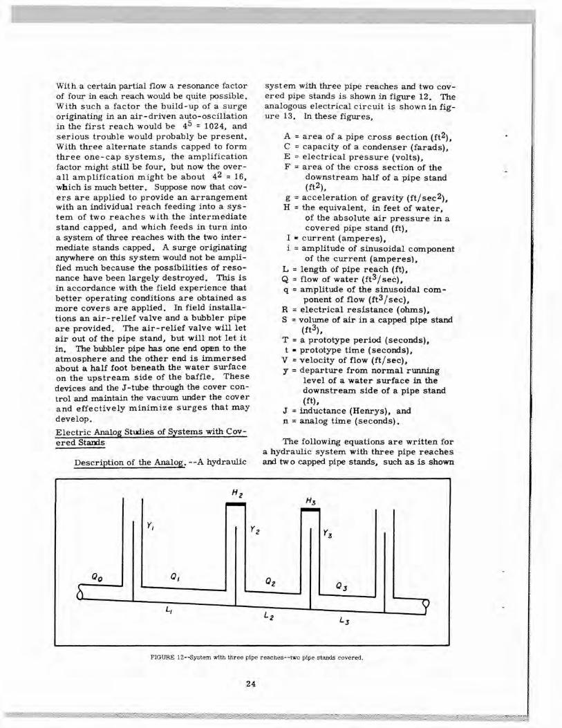
Description of the Analog. - -A hydraulic
system with three pipe reaches and two cov-ered pipe stands is shown in figure 12. Theanalogous electrical circuit is shown in fig-ure 13. In these figures,
A = area of a pipe cross aection (ft2),C = capacity of a condenser (farads),E electrical pressure (volts),F = area of the cross section of the
downstream half of a pipe stand(ft2),
g = acceleration of gravity (ft/see2),H = the equivalent, in feet of water,
of the absolute air pressure in acovered pipe stand (ft),
I current (amperes),i = amplitude of sinusoidal component
of the current (amperes),L length of pipe reach (ft),Q = flow of water (ft3/seã),q amplitude of the sinusoidal com-
ponent of flow (ft3/sec),R = electrical resistance (ohms),S = volume of air in a capped pipe stand
(It3),T = a prototype period (seconds),t • prototype time (seconds),
V velocity of flow (ft/see),y departure from normal running
level of a water surface in thedownstream side of a pipe stand(ft),
J = inductance (Henrys), andn = analog time (seconds).
The following equations are written fora hydraulic system with three pipe reachesand two capped pipe stands, such as is shown
FIGURE 12--System with three pipe reaches--two pipe stand covered.
24
J3
- rO \_1_ T12
T2 Tc3_ _____ ___
FIGURE 13--Analogous electrical circuit for system with three pipe reaches--two pipe standscovered.
in figure 12, and for the analogous electrica' where the quantities i and b in the term i Sincircuit1 figure 13.
The continuity ef4uations bn will be chosen to represent, in the analog,for the hydraulic system are
the term q< SiIl (
tt) in the hydraulic system.
+
Sinl air
\The electrical dynamic equations are
dy1- F1 -- - Q1 =
(34) d11dy2 E1-J1---E2=O
Qi - F2 -- - Q2 = 0
d12dy3 E2 - J2 -
- E3 = 0 ......... (37)Q2-F3---Q30
-
The dynamic equations for the three pipe d13E3 - j3
-
reaches are
Li dQ1
H2F2 Corresponding quantities in the hydraulic= Yl +
s2
Y2 and electrical systems will be as follows:
Hydraulic
ElectricalL2dQ2
-
I(
HF21 + I Y2 .
.
. (35) Quantity of flow
Current.A2gdt S2 ,J
H3F3 Water surface elevation
Voltage
+___
3
0S3 Inertia
Inductance
L3dQ3
H3F3 \ Storage
Capacity
-
i +A3gdt
S3!l Y3 Frictional drag
Resistance
The electrical continuity equations are Time
Time
Before an analog can be set up, it is10 + I Sin bn - C1
- Ii = 0 necessary to write a set of correlation equa-
(36)tions and to convert the hydraulic equations
dE 2
i
- oI
-Cj- -
2} to electrical equations by substituting the cor-
relation equations into them. The capacities
12 - C3
- 13 = 0and inductances required In the electrical cir-cuit are found by this process.
25
The correlation equations adopted were
= E1
..........
S2
= H2F2 E2
S3(38)Y3 = H3F3 E3
Q =1,0001
t =1,040,000n
The process of transformation may beillustrated as follows:
Transform the equation
I2
\
dyQ0+q0SinI -t\T0 j -F1---Qj0.
By substitution from the correlation equa-tions,
1,00010 +1,000 i0Sin(l0)6(l.04)n -
dE1F1
- 1,00011 = 0(1.04)(10)6 dn
or, after reduction,
F1
dE1L+i Sin bn -
--(10)(1.04) dn
A comparison of the transformed equa-tion with the first of equations (36) will showthat the value of C1 must be
F1Cj-
(10) (1.04)
The second of the hydraulic equations,
dy2Qi - F2 -- - Q2 0,
becomes
S2
dE21, 000 I - F2
H2F2 (1.04) (10)6 dn -
1, 000 12 = 0,
or
F2S2
dE2
H2F2(10)9(l.04) dn
and a comparison with the second of equa-tions (36) shows that
S2C2 =
H2(l0)9(1.04)
The first of the dynamic equations inthe hydraulic set is, from equations (35),
L1 dQ1 -
H2F2Y1+
Y20.S2
This becomes, on substitution from the cor-relation equations,
L1
1, 000 d11
A1g (1. 04)(10)6dn - E1 + E2 = 0
Comparing this equation with the cor-responding electrical equation, which is thefirst of equations (37), shows that the induct-anc e required is
L11 A1g (1,040)
The only difficulty encountered in thisH2F2
process is that the quantities
and
H2F2
H3F3
H3F31 + , and and 1 + can-
not be differentiated. It is therefore nec-essary to use an average value for bothH2F2
This analog will work at around 10, 000cycles per second. This frequency is highenough so that air-core coils can be used.This provides an accurate analog but record-ings must be made from an oscilloscope.A second analog, to be described later, wasmade with iron-core coils in order to workat frequencies low enough to permit record-ing with an oscillograph. This permittedsimultaneous recording of all the pertinentquantities. These two analogs will be re-ferred to hereafter as the high-frequency andlow-frequency analogs. The iron-core coilsused in the low-frequency analog did not per-mit determinations as accurate as those ob-tained with the air-core coils of the high-frequency analog. The high-frequency analogwas used to check the computed frequenciesaixi the low-frequency analog was used wheresimultaneous recordings were required. Thenatural periods obtained with the high-f re-quency analog are shown in table 2.
Table 2
NATURAL PERIODS OF THE PROTOTYPEHYDRAULIC SYSTEM AS OBTAINED FROMOPERATION OF THE HIGH FREQUENCY
ANALOG
Open Capped Prototype periodstands stands
(seconds)
1
0
64.0
1
1
94.5 24.8
1
2
120.9 32.5 21.0
1
3
148.6 41.6 24.1
Table 2 shows that there is more than onenatural period for each system except thefirst. There should be a number of periodsequal to the number of pipe reaches in thesystem. However, only three periods whereresonance occurs could be found for the sys -tem with four pipe reaches and three cappedstands.
Low-Frequency Analog. - -This analogwas computed to work in the neighborhood of50 cy des per second, permitting the sequenceof starting oscillations to be recorded on anoscillograph. Equations (34), (35), (36), and(37) were used with the correlation equations
E1 =y1
H2F2E2r S2 Y2
..........H3F3
IE3
y (39)
Q = 1, 000 I
t = 3, 320 n
These correlation equations lead to
Cl - 2.58(l0y farads
=
=
= (0.86)(10)
farads, andJi
2 =
= J4 = 3.93 Henrys.
The resistance of the inductances was 200ohms. An iron core with an air gap is usedto obtain the high inductance required in thissystem. In such an analog, the resistancesmust be small compared with the criticalresistance
Rc
jr,
if the resonance points are to be clearlyshown. A check will show that both sys-tems fulfill this requirement.
Operating Results with the Low-Fre-quency Analog. - -The observed resonancepoints are shown in table 3.
Table 3
NATURAL PERIODS OF THE HYDRAULICSYSTEM AS OBTAINED FROM THE LOW
FREQUENCY ANALOG
Open Capped Natural periodsstands stands
seconds
1
0
661
1
102
251
2
128
34
211
3
158
44
25
27
Again, for one open stand and three capped
These equations are computed directly fromstands there should have been four frequen-
equations 1 and 2cies, but, as before, only three were found.
Computed Periods. --The computed pe-
Resonance Spectra. --The curves of fig-
nods are as shown in table 4 ures 14, 15, and 16 show four resonancespectra obtained by feeding the output of thelow frequency analog into an oscillographrecorder. A diagram of each of the fourspectra shows the system represented. Theoscillatory component of flow fed into thesystem is shown at the bottom of the sheetin each case. The imposed period is shownby th€ scale near the center of each figure.The periods are shown for a prototype struc -tune with 5-foot-diameter pipe stands andwith 1,320 feet of 2-foot-diameter pipe.Since the scale of all the q records is thesame (within about 4 percent), the resonancefactors can be obtained by comparing theband widths of the q records. For example,
_
4OEEEEEEEEEI ___ Eli
i,L.oH.51 .o
--__
--" -- -
FIGURE 14- -Resonance spectra for system with single pipe reach and for system with twopipe reaches--common stand covered.
Table 4
COMPUTED PERIODS
Open Capped Computed periodsstands stands
seconds
1
0
66.41
1
90.1 2661
2
107.0 36.0 22.41
3
Not comnuted
28
:I:EEEEEEEEEOrj3 __ E
0
Li- 3
:
q7-
-00Li-:i 3.0
q/q0
0
-
-0
0.5
.0
.5
2.0
2.5
3.0
3.5
4.0
4.5
5.0
5.5
6.0Tj'1
FIGURE 15- -Resonance spectra for system with three pipe reaches--two stands covered.
0 q /3 __ - - - - -I. .
c,
0
- - ---- - - - -0
3 0-
-
-
- --- ----
.
Z 2 0.0
P 0 -- (1
__
. - - -
-
_
:_FIGURE 18--Resonance spectra for system with four pipe reaches- -three stands covered,
29
I II
II
1
1I
I
I
I 77fl
II I'fl
I1 I I"'MELI II
rim
•HI
1fl HE1I
!1 iI'HI
I
I
I
IL] 1 1 "fl
I Fl N i"I-
I
-L
7
1110
iiio
V
04)0
4)
a8i
0o
0.
30
Table 5
COMPARISON OF NATURAL MODE PERIODS AS OBTAINEDFROM COMPUTATIONS, FROM ANALOG OPERATION AND
FROM EXPERIMENTS ON THE LABORATORY MODEL
Open Cappedstands stands
Computed*
1
0
21.91
1
30.1, 7.31
2
36.5, 9.0, 5.2
* Undamped natural period** Points of maximum resonance
on the system with no covers the resonancefactor at a period of 66.4 seconds is about 4.It has been noted that there is some variationin observed periods in different runs with thelow -frequency analog. This is believed to bedue to the use of iron-core coils.
Checks and Correlations. - -In order toobtain comparative figures for periods, com-putations were made for the hydraulic modeland the analog was modified to represent themodel by changing the condensers. Testswere run on the analog and the laboratorymodel was operated with zero, one, and twocovers under various Imposed periods ob-tained by operation of the head box plunger
Computation of Resonance Factors. - -When a pipe line Is in the design stage, itis important to know whether the proposedarrangement would tend to surge and, if so,how covers could be used to control it. If aline has been built and is known to surge thenit becomes important to determine how toplace covers to stabilize the line.
The amplification estimates requiredcan be best made by using the formulas ofconclusion (n) together with the curves offigure 10. This is an approximate method
Natural periods- -secondsAnalog**
Lab model**
21.6
21.531.5,
7.5
35.0,
7.040.3,
10.0
42.0,
9.2
motor. A comparison of the results ob-tained is shown in table 5.
Table 6
PIPE DIMENSIONS AND RELATED QUANTITIES
Pipe Pipe Pipe stand Period- -secPipe length diameter diameter T = 2
[Pitreach feet feet feet. A F1* V
5.0 18.591 1, 320 2.50 4.91 78.3
4.5 14.972 1,325 2.00 3.14 88.0
4.5 14..973 1,321 2.00 3.14 87.9
4•5 14.974 1,318 2.00 3.14 87.8
4.0 11.735 1,319 1.67 2.19 93.1
4.0 11.736 1,322 1.67 2.19 93.2
4.0
* This figure allows for a baffle wall 5 Inches thick.
31
and neglects the possibilities of resonancesIn the higher males, but it has the advantagesof simplicity and generality and appears tobe adequate for these purposes. The use ofthe curve for H = 0.125 in figure 10 is rec-ommerided for these computations as illus-trated in the following applications. Althoughthe possibility of resonance to an auto-osdil-lat Ion arising in the first reach only is illus-trated, a similar computation should be car-ried through for an auto-oscillation occurringin any subsequent reach it' the natural periodsvary enough to warrant It, An auto-oscilla-tion wifi have the period of the reach in which
it originates.
Example. - -Consider the case of a lat-eral with the six pipe reaches whose dimen-sions are given in table 6. The naturalperiod of each reach is shown in the lastcolumn. The periods (last column in table 6)are close enough togther to cause trouble.Computations of the over-all resonance factorfor an auto-oscillation occurring in the firstreach are shown In table 7,
The amplification factors are read fromfigure 8 using the curve for R = 0.125. Thiscurve shows a peak amplification factor ofabout 4, which is reasonable for pipes of thissize. A closer evaluation is probably un-warranted since the friction loss depends onthe flow. The value of used for Reach 1 inthis computation is taken as unity since thedisturbance is assumed to originate in thisreach. The amplification factors for the in-dividual reaches are shown in the last column.The figure at the bottom of this column is theproduct of the individual amplification factorsand represents the number of times the am-plitude of the original disturbance would beamplified at the end of the line. Note thatwe do not know the amplitude of the originaldisturbance and cannot, therefore, computethe actual final amplitude. This will be theusual situation when designs are being pre-pared. Field observation, however, indicatedthat the line will probably operate satisfacto-rily if the over-all amplification does not ex-ceed 20, This arrangement does exceedthat factor and it would therefore be wise totake steps to reduce the over-all amplifica-tion.
Suppose a cover is placed on alternatepipe stands. This will group the pipe reachesinto three systems with two reaches in each.The computation is shown in table 8. Thisline should noW be satisfactory for any dis-turbance originating in the line. If, however,this line is a lateral supplied from a longerline having an oscillation with a period ofabout 125. 5 seconds, then the resonance fac-tor at the end of the line would be (4.0) (4. 0)(3. 5) 56 and a troublesome surge would bea distinct possibility.
Table 8
RESONANCE COMPUTATION FOR LINE WITHALTERNATE PIPE STANDS COVERED
L1
L2\ /fi1T\ 125,5Pipe
FT
g
\
) Threac es _________ _______________________ _______ _________
1-2 18,59
690.8 125.5 1.000 -
3-4 14,97
840.4 124.2 1.010 4.05-6 11.73
1205.9 131,7 0.953 3_S
32
The effect of placing a cover on all ofthe pipe stands except the first and last maybe estimated as follows. All of the pipereaches are now grouped into one systemwhose period is
The line should now be strongly stable.An air-driven auto-oscillation occurring inthis system would be of small amplitule andcould not be amplified. Even though a periodof about 249. 8 seconds were imposed on itthrough its connection to the main line, therewould still be no trouble since a resonancefactor of about 4 or less is all that could beexpected.
It will be noted that no attempt has beenmade to completely eliminate all oscillations,which is probably impossible. In all casesthe purpose has been to apply covers insuch a way as to reduce the amplitude of pos-sible oscillations to a point where they willnot interfere with the operation of the line.If these amplitudes are kept within bounds
so that flow over the baffles does not cease,this purpose will be accomplished.
DIVISION OF WORKAND ACKNOWLEDGMENTS
C. S. Hale as Construction Engineer ofthe Coachella Division was in charge of allwork done in the field. P. W. Terrell di-rected the technical phases of the designwork, R. E. Glover was in charge of analyt-ical computation of periods and with the de-velopment of analog devices. W. P. Sim-mons, Jr. performed the experimental workin the laboratory. Kenneth Fienup contributedto much of the early progress toward solutionof the problem by making analyses of condi-tions in pipe lines known to surge. G. G.Balmer contributed the analysis of the sys -tern with one cover, made computations ofperiods for comparative purposes, and as-sisted with the design of the analogs. C. S.Daum developed the low-frequency analogwhich produced the resonance spectra forsystems with one, two, and three covers.The Concrete Conduit Company of Colton,California, modified one of the Coachellalaterals at its own expense to assist withthe investigations. This work helped mate-rially to clarify certain aspects of the surg-ing phenomena.