Clydesdale Spinal System Navigated Interbody Inserter
Navigated CD Horizon Solera Voyager System with IPC™ Powerease™ System
Navigated Stealth-Midas™ Powered Drilling System
Direct Lateral Dilator with MAST™ Dilator Tracker and Stimulating Adapter Clip
4
StealthStation NavLock™ Instrument Set (9734833)
StealthStation Spine Referencing Set (9734495)
Disposable Perc Pin 100mm (9733235) 150mm (9733236)
SYNERGY OLIF360 SINGLE-POSITIONINSTRUMENTS AND SETUP
Navigated PAK Needle (9733498)
O-arm Sterile Tube Drape (optional)(9732722)
Navigated Clydesdale Trial Set (9734834)
Navigated CD Horizon™ Solera™ Complete Percutaneous Taps/ Drivers Set (9735465/9735466)
Spheres (8801074)
Navigated Inserter Set (9734734)
Navigated Lateral Disc Prep Instrument Set (SPS02868)
Disposable Direct Lateral Dilator Kit, Sterile (945NSD2750)
5
EQUIPMENT AND ROOM SET-UP
For a navigated surgery, the OR should be equipped with the O-arm Image Acquisition System, the Mobile Viewing Station (MVS), and the StealthStation S7 or S8 System (Figure 1a). Plug the MVS into a power source; connect the MVS to the O-arm System, and power on the system. Next, power on the StealthStation System and start the StealthStation™ Spine software. Connect the MVS to the StealthStation System network port with a network cable or a crossover cable.
The equipment set-up for a SynergyOLIF360 Single-Position Procedure has the StealthStation Camera Cart positioned near the patient's feet; however, it is the surgeon's preference as to whether the Camera Cart is positioned near the patient's feet or head.
Figure 1a
Patient's Head
O-arm Image Acquisition System
Main Cart
Patient's Feet
Camera Cart
Mobile Viewing Station
6
SYNERGY OLIF360 SINGLE-POSITIONEQUIPMENT AND ROOM SETUP
When positioning the O-arm System for the procedure, place it around the patient table approximately seven inches closer cephalad from the anatomy to be imaged (Figure 1b). The gantry should then be translated in the direction of the patient’s feet for imaging. This will allow the gantry to be placed in a “park” position and remain in the sterile field throughout the procedure, if desired (Figure 1c).
The camera should be positioned so that the camera has an unobstructed line-of-sight to the Reference Frame which will be placed into the patient. Position the surgeon’s monitor near the patient’s side, opposite from the surgeon.
Figure 1b
Figure 1d
Figure 1c
Helpful Hint If the O-arm System will remain in the sterile field during the procedure, drape the O-arm System gantry using the O-arm IAS Sterile Tube Drape during the positioning of the system. If the O-arm System will be removed from the sterile field, place and clamp two half-drapes over the sides of the patient prior to positioning in the sterile field maintaining sterility around the patient while closing the gantry of the O-arm System (Figure 1d).
Figure 1cFigure 1b
7
In the StealthStation Spine Software, complete the “Select Procedure” and then "Select Surgeon" tasks. Continue through the software by completing the “Set-Up Equipment” and “Verify Instruments” tasks to reach the “Acquire Scan” screen.
StealthStation Spine Software Workflow1. Select Procedure and Select SurgeonOpen the "Select Surgeon" menu and select the Primary Surgeon and the Surgical Procedure to be performed.
3. Acquire ScanThe navigation system will remain on this screen until the O-arm System image acquisition step has been performed.
2. Verify InstrumentsCheck that the toolcards for all the navigated instruments needed for the procedure are shown on this screen. Instruments can be verified now or during a later step, but the toolcard for the instrument must appear on this screen to be verified and tracked.
SYNERGY OLIF360 SINGLE-POSITIONEQUIPMENT AND ROOM SETUP
8
ANTEROLATERAL ACCESS
DISC PREPARATION
INTERBODY PLACEMENT
ROD AND SET SCREW
PLACEMENT
n Determine entry pointsn Mark skin
n Make skin incisionn Place Retractor
n Tap and use projection to determine screw length and diameter
n Save projection to mark entry point
n Repeat for other levelsn Place screws
PEDICLE ACCESS
PREPARATION
n Drape patient, bring O-arm System in field, and remove after image acquisition
n Drape O-arm System, bring in and leave in field after image acquisition
n Percutaneous Reference Pin with Percutaneous Reference Frame
n Assess implant placementn Tighten and shear set screws
n Remove implant tabsn Close skin incisions
n Navigated Dilatorn Navigated Awl-tip Tapn Navigated Driver
ACQUIRE 3D CONFIRMATION
IMAGE
n Navigated Disc Prepn Navigated Interbody Trials and Insertern Stealth-Midas
n Pass rodsn Place and provisionally tighten set screws
n Trial for implant sizen Place bone graft in the spacer
n Place the interbody spacern Close skin incision
n Perform per surgeon's usual manner
TAP/PLACE SCREWS
BILATERALLY
n Determine entry points n Mark skin n Make skin incision
OR
9
INSTRUMENT VERIFICATION
Attach the Spheres to a blue Reference Frame from the Spine Referencing Set and the NavLock™ Trackers from the NavLock™ Set. Check the Spheres to ensure they are secure. Next, attach the NavLock™ Trackers to the instruments.
Place each instrument tip into the divot in the blue Reference Frame and hold perpendicular (Figure 2a) and visible to the camera until a confirmation color is seen. Use the tracking view in the lower right of the screen to ensure the camera is tracking the Reference Frame and instrument correctly (Figure 2b).
l Successful verification is indicated by a chime and a transition to green on the instrument toolcard.
l Failed verification is indicated by a “bonk” sound and indicates that the instrument may be positioned improperly in the divot or is bent/damaged. Inspect the instrument; if it is bent/damaged, do not use.
l If no sound is heard when the instrument is touched to the divot, this may indicate that the camera cannot see either the instrument or the frame.
Figure 2a
Figure 2b
Navigated Instrument
Reference Frame
Helpful Hint Assigning an instrument to a specific-colored NavLock® Tracker will eliminate the need to switch the tracker from one instrument to the next throughout the procedure. As an example, the grey tracker could be assigned to the tap and the orange tracker could be assigned to the driver.
Helpful Hint OR Staff can verify instruments before the surgeon enters prior to reference frame placement.
StealthStation S8 System Software
10
PATIENT POSITIONING
Surgical Synergy Spinal Workflow
11
Surgeons should be familiar with performing a traditional Oblique Lateral Interbody Fusion, per the OLIF25 Surgical Technique, before incorporating the navigated workflow into their practice.
Preoperative planning can be useful in determining:
§ Location of the iliac crest and lower ribs in relation to the disc space of interest
§ Position of the psoas, anterior vasculature, posterior nerve structures and the kidneys via axial MRI (Figure 3a)
§ The oblique angle of entry into the disc space § Curvature of the spine, spinopelvic alignment, and
lordosis restoration goals
Patient Positioning
Right lateral decubitus, or left side up, is the preferred position for an oblique lateral approach based on vasculature positioning. However, the surgeon should consider ease of access, surgeon preference, and preoperative images in determining which side to approach. Correction can be achieved equally from either the convex or concave side of the curve. Use of a radiolucent flat table top is recommended.
Position the patient's posterior spine close to the edge of the table to allow clearance of instruments during placement of bottom pedicle screws. Position the patient laterally at approximately 90° to the table with the upper hip extended, not flexed, with optional support under the waist to provide stability. An axillary roll can be placed to protect the
neurovascular structures in the axilla. This patient positioning allows for access to the lumbar spine via other lateral procedures without the need to reposition the patient. The top leg of the patient should be straight to allow for access to L5-S1, if desired. The bottom leg should be flexed at approximately 45° to improve stability of the patient. Padding, such as bolsters, are placed beneath and in between the legs to stabilize the lower extremities. Bend the patient’s arms at the elbow if the O-arm System will remain parked during the procedure (Figure 3b). Extreme flexion to relax the psoas is not required because the approach is outside or within the anterior portion of the psoas (ante-psoas). Breaking of the surgical table is not required, even if the patient has a high iliac crest and deep seated L4-5 disc space, as the oblique lateral approach is anterior to the iliac crest.
The patient is secured to the surgical table with tape at at least three locations:
1. Just beneath the iliac crest, ensuring that the PSIS is not covered
2. Over the thoracic region, just beneath the shoulder,but distal to the axilla
3. Over the shin to the back of the table
Circumferential taping, or a complete 360° around the table and patient, will help to ensure patient stability and navigational accuracy. A surgical towel can be placed between the skin and tape.
Figure 3a
Psoas
Right
Left
Psoas
VenaCava
Aorta
SynergyOLIF360 Trajectory
Figure 3b
INTRODUCTION AND SURGICAL OVERVIEW
Helpful HintPlace the patient on the table so the patient’s anterior is facing the surgeon. This will keep the Percutaneous Reference Pin opposite to the surgeon and out of the way once it is placed.
*NIM-Eclipse E4 Spinal System is manufactured by Medtronic Xomed, Inc. Distributed by Medtronic Sofamor Danek USA, Inc.
The Direct Lateral Dilator described in this technique is compatible with neuromonitoring. Electrode placement may be performed using the surgeon’s standard electrode placement technique.
After the patient is asleep, needle recording electrodes are placed in the innervated muscles in the legs to monitor the affected nerve roots during the procedure. Please follow the instructions below, as well as the accompanying electrode placement guide, to correctly place the electrodes in the appropriate muscles for the desired levels.
1. Electrodes are placed prior to patient draping and the establishment of the sterile field.
2. Clean the areas with alcohol wipes.
3. The green lead ground electrode should be placed between the stimulator and the monitoring electrodes in a location where the bone is close to the skin and the electrode will not contact muscle.
4. The white stimulus return electrode should be placed near the location of stimulation. Connect the Probe lead wire to the instrument jack of the patient interface module.
5. Tape all of the electrodes securely in place and plug the leads into the patient interface box and turn on the NIM-Eclipse™ E4 Spinal System* to begin monitoring.
Neuromonitoring (Optional)
Helpful HintLet the anesthesiologist know EMG monitoring will be used during the procedure to ensure that no neuromuscular blocking agents are administered during monitoring. During intubation, a fast-acting neuromuscular blocking agent should be used.
SYNERGY OLIF360 SINGLE-POSITIONINTRODUCTION AND SURGICAL OVERVIEW
13
REFERENCE FRAME PLACEMENT
When performing a SynergyOLIF360 Single-Position Procedure use of the Percutaneous Reference Pin with the Percutaneous Reference Frame is recommended. Pins are available in 100mm and 150mm lengths. The preferred method places the pin just lateral to the posterior superior iliac spine (PSIS) much like the trajectory of an iliac screw, which drops the reference frame out of the way and does not pose potential line-of-sight obstacles between the camera and the screw placement (Figure 4a). This option is described below.
Using palpation, locate the PSIS on the patient. Mark the skin a little medial and inferior to the PSIS to verify the appropriate location to place the pin. Make a stab incision and locate the Cannula with the Dilator just lateral to the PSIS, taking into account patient morphology and line of
sight for the reference frame . Place the Dilator/Cannula into the incision through the tissue until it contacts bone. Once docked, the Dilator/Cannula assembly is tapped with a mallet to make an indentation in the bone for the pin. While holding the Cannula in place remove the Dilator and insert the pin through the Cannula. Place the Tap Cap on the pin and rotate the cap so the arrow on the Tap Cap points toward the camera. Orient the Pin/Tap Cap assembly approximately 30° toward the midline of the patient and then angle it 30° toward the foot of the patient. Use an impactor to drive the pin into the bone until the Tap Cap contacts the top of the Cannula (Figure 4b). Remove the Tap Cap from the pin and attach the Percutaneous Reference Frame to the pin (Figure 4c).
Figure 4bFigure 4a
Figure 4c
ImportantEnsure the Reference Frame is properly secured to anatomy. Make certain there is minimal skin and soft tissue tenting, as this may lead to drift motion of the pin. Neglecting to verify that the Reference Frame is secured could result in navigational inaccuracy if the hardware moves in relation to the anatomy after registration is complete.
14
IMAGE ACQUISITION
At any time when fluoroscopy is used (2D or 3D acquisition) all personnel who are not wearing protective lead apparel should stand at least 15 feet (457.2cm) from the O-arm™ System with a certified moveable lead shield between themselves and the O-arm™ System to avoid unnecessary radiation exposure.
Establish the surgery site using 2D fluoroscopy scout images as needed. On the control panel, select the patient
size, anatomy, and orientation. With the patient isocenter, position the O-arm™ System gantry to perform a 3D spin. Following the 3D spin, the images are transferred automatically to the StealthStation™ System. Should 2D images or a second 3D spin be desired, four preset O-arm™ System gantry positions may be set up and saved. Once the images are transferred, the O-arm™ System can be moved out of the way and into the park position.
Scatter plot showing the shape of isodose curves for the maximum technique factors for the O-arm™ 02 Imaging System. Please refer to the end of this surgical technique for more information on the shape of isodose curves for the O-arm™ 1000.
�n Protocol: Abdomen Standard Large
�n Technique: 120 kVp, 330 mAs
O-arm™ System Isodose Curve
-800-400-2000200400600800
-600
-500
-400
-300
-200
-100
100
200
300
400
500
600
cm
0cm
-600
0.25mR
0.5mR
4 mR
2 mR
1 mR
8 mR
16mR
32mR
Ideal Location for Moveable Lead Shield
Rear
15
PROCEDURE STEPS
Surgical Synergy Spinal Workflow
16
PEDICLE ACCESS PREPARATION
Determine the trajectory for pedicle tapping and mark the skin bilaterally at each level to be instrumented. Use the Navigated Dilator/Dilator Tracker or the Navigated PAK Needle to identify the trajectory for tapping and mark the skin bilaterally directly over where the screws will be placed. Under "Projection" tab on the StealthStation S8 System, add a tip extension, such as 1mm × 100mm, to the tip of the instrument. The projection may be lengthened as needed to accommodate patient size (Figures 5a and 5b).
Optional Step
On the StealthStation System, choose the "Tool" tab to select the appropriate Stealth-Midas tip to display the Stealth-Midas dissecting tool. Use the Stealth-Midas to drill at the desired trajectory. Choose the "Projection" tab on the StealthStation System to create a projection and select "Save Projection" to save your plan (Figure 5c).
Figure 5a
Figure 5b
Figure 5c
17
PEDICLE PREPARATION AND SCREW LENGTH MEASUREMENT
If using cannulated extended tab screws, assemble the Awl-Tip Tap by first retracting the collar on the appropriate size tissue protector. Insert the Awl-Tip Tap. The tissue protector can be retained on the tap by locking it in the first position (Figure 6a).
Insert the assembly into the skin incision and verify the trajectory on the surgeon monitor (Figure 6b). Advance the assembly until it contacts the bone. A virtual tip projection can be selected under the "Projection" tab to provide additional guidance (Figure 6c). Pull back on the tissue protector collar, and advance the tap to its desired depth. Once the tap has been advanced to the ideal depth, create a reverse projection under the "Projection" tab and then select "Save Projection" (Figure 6d). This will save the trajectory to be used as a virtual guidewire which may be recalled during subsequent screw placement. This projection also indicates the screw length and diameter for subsequent screw placement. Remove the Awl-Tip Tap and Tissue Protector for screw placement. The tissue protector can be held down against the bone to cover the tap threads and re-lock the tissue protector to the tap during removal.
Figure 6c
Figure 6dHelpful Hint When creating the initial entry for the top, use oscillate to create the pilot hole. Minimize excessive forward pressure and force, as this may rotate spinal segments and affect accuracy.
Figure 6b
Figure 6a
Flush Exposed
Awl-tip Tap
Tissue Protector
EXTENDER, CAP, AND SCREW ASSEMBLY
Before a screw can be inserted into the pedicle, the Tab Extenders (6642007) and Cap (6642006) (Figures 7a and 7b) must be assembled with the Multi-Axial Extended Tab Screws. To assemble the Tab Extenders, insert the Multi- Axial Extended Tab Screw Head into the Extenders until locked. With both Tab Extenders locked onto the Multi-Axial Extended Tab Screw Head, insert the Cap into the forked tips of the Tab Extenders.
Note To ensure Cap is locked onto Tab Extenders, listen for an audible click.
Figure 7a
Figure 7b
18
19
SCREW INSERTION
Screw insertion should be performed at this time. Thread the navigated driver into the head of the screw. Remove the Tissue Protector, if still in place, and recall the virtual guidewire if saved during pedicle preparation (Figure 8a). Under the "Tool" tab, select the appropriate screw width and length. Align the screw extender and driver with the virtual guidewire and advance the screw being careful that the screw assembly is not advanced too far (Figure 8b). If the screw head is placed against the bone, it will lose its multi-axial capabilities and make it difficult to connect the screw assemblies during subsequent steps.
Figure 8a
Figure 8b
20
Note If particularly hard bone is encountered (for example dense, sclerotic bone), it might be helpful to prepare the pedicle by creating a cortical breach at the pedicle entry point as per the surgeon's standard technique prior to placing ATS implant.
Note See the CD Horizon Solera Voyager 4.75 or 5.5/6.0mm Surgical Technique for placement guidance and instructions for use.
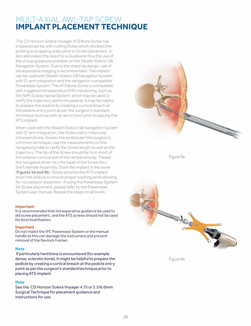
The CD Horizon Solera Voyager ATS Bone Screw has a tapered awl tip with cutting flutes which obviates the probing and tapping steps prior to Screw placement. It also eliminates the need for a Guidewire thru the use of the virtual guidewire available on the Stealth Station S8 Navigation System. Due to the sharp tip design, use of intraoperative imaging is recommended. The implant can be used with Stealth Station S8 Navigation System with O-arm integration and the navigation-compatible Powerease System. The ATS Bone Screw is compatible with triggered intraoperative EMG monitoring, such as the NIM-Eclipse Spinal System, which may be used to verify the trajectory within the pedicle. It may be helpful to prepare the pedicle by creating a cortical breach at the pedicle entry point as per the surgeon's standard technique (such as with an awl or burr) prior to placing the ATS implant.
When used with the Stealth Station S8 Navigation System with O-arm integration, the Screw size is measured intraoperatively. Assess the pedicle per the surgeon’s common technique. Use the measurements on the navigated probe to verify the Screw length as well as the trajectory. The tip of the Screw should be 1cm short of the anterior cortical wall of the vertebral body. Thread the navigated driver into the head of the Screw thru the Extender Assembly. Dock the implant in the bone (Figures 9a and 9b). Slowly advance the ATS implant down the pedicle to ensure proper tracking while allowing for viscoelastic expansion. If using the Powerease System for Screw placement, please refer to the Powerease System user manual. Repeat the steps on all levels.
Figure 9b
Figure 9a
ImportantIt is recommended that intraoperative guidance be used to aid screw placement, and the ATS screws should not be used for bicortical fixation.
ImportantDo not mallet the IPC Powerease System or the manual handle as this can damage the instrument and prevent removal of the Navlock tracker.
21
LOCALIZATION
Use the narrow Passive Planar Ball-tipped Probe and target between the middle and anterior third of the disc space with an oblique trajectory outside of the psoas muscle. Mark the corresponding skin incision location which should be approximately 5cm anterior to the direct lateral location (Figure 10a). A projection can be helpful to locate the trajectory to the disc space. Under “Select Projection" on the StealthStation System, add a tip extension to the tip of the instrument (Figures 10b and 10c). The projection may be lengthened as needed to accommodate patient size.
Figure 10a
Figure 10c
Figure 10b
Single-level Incision L4 – 5
Two-level Incision L2 – 4
Skin Incision Zone
22
Helpful HintAt any point during the procedure, navigation accuracy can be evaluated by using the first Direct Lateral Dilator/MAST Dilator Tracker on known bony landmarks.
ImportantPlease see the NIM-Eclipse Spinal System package insert and user’s manual for complete instructions and a list of warnings, precautions, and other medical information. The NIM-Eclipse Spinal System is intended for use to record, monitor, and stimulate/record biopotential signals including electromyograph (EMG), evoked response and nerve/muscle potentials, and intraoperative diagnosis of acute dysfunction in corticospinal axonal conduction. The system provides feedback to the surgeon and OR team to assist in the localization and assessment of spinal nerves and verification of placement of spinal instrumentation to avoid injury to at-risk nerve roots.
Figure 11a
After making a single skin incision, the subcutaneous fat layers are dissected until the abdominal musculature is reached. The external oblique fascia will be the first plane encountered and is the only layer that will need to be sharply incised. A Kelly Clamp may be used to bluntly spread through the fibers of the external oblique, internal oblique, and transverse abdominis muscles. All dissection is done in line with the muscle fibers as these muscle layers run in opposite directions.
After bluntly penetrating the transversalis fascia, the yellow retroperitoneal fat is exposed. Once inside the retroperitoneal space, the index finger is used to follow the internal abdominal wall posteriorly down to the psoas muscle, which can be visualized. The finger or a blunt instrument is used to sweep the peritoneal contents forward, including the ureter, which reflects with the peritoneum, and the retroperitoneal fat anteriorly past the anterior portion of the psoas clearing to the anterior vertebral body (Figure 11a). Direct visualization may be employed in addition to tactile feel to ensure a safe approach to the disc space free from vascular, peritoneal and nerve obstructions. The fat overlying the psoas muscle can be swept in a cephalad and caudal direction as well as dorsoventral with handheld retractors in order to visualize placement of the Direct Lateral Dilator/MAST Dilator Tracker. Use of hand-held retractors placed between peritoneal contents and the probe will also minimize risk of injury to ureters and vascular structures anteriorly. A kitner or cloth-based dissector may be used to sweep soft tissue structures anteriorly. An additional retractor can be used to retract posteriorly to ensure direct visualization is acheived.
After a safe retroperitoneal pathway to the anterior portion of the psoas has been established under direct visualization, the Direct Lateral Dilator/MAST Dilator Tracker is guided down to the disc space in front of the psoas while using the finger or handheld retractors to protect the peritoneal membrane and retract retroperitoneal fat. Avoiding the psoas muscle will minimize the potential risk to the nerves within the psoas and to the psoas muscle itself. Approaching the spine obliquely as opposed to direct lateral will further ensure the instruments work away from the peritoneum and anterior vascular structures. It is important to maintain the proper trajectory during dilation. On the StealthStation System, a cylindrical projection may be added to the Direct Lateral Dilator to get an approximation of where the Retractor will be positioned on the lateral spine. The Direct Lateral Dilator/MAST Dilator Tracker includes an insulated shaft that enables controlled electrification at the tip of the devices (Figure 11b). After the proper position has been established, current may be delivered to monitor for any neural structures as the probe is passed anterior to the psoas and into the disc space. If desired, the NIM-Eclipse E4 System screen can be imported as one of the views on the StealthStation Monitor.
SYNERGYOLIF360 SINGLE-POSITION SITE ACCESS
Helpful HintEntering the transversalis fascia obliquely from anterior in the incision to posterior to the quadratus muscle will prevent inadvertent entry into the peritoneum. Palpating the quadratus muscle, followed by the tip of the transverse process and finally the psoas muscle, will help verify that the correct retroperitoneal plane is being entered and ensures that the peritoneum is not compromised.
Figure 11b
23
ImportantAll disc preparation instruments, including the Cobb and Shavers, can enter obliquely through the Retractor and then be turned orthogonally to allow the surgeon to work orthogonally across the disc space and release the contralateral annulus. The Retractor should be slightly opened to allow for the instruments to turn orthogonally. A mechanical or digital protractor may be used to assess the oblique and lordotic angles of entry into the disc space, but the location of the instruments is confirmed using fluoroscopy.
SYNERGY OLIF360 SINGLE-POSITIONSITE ACCESS
NoteFor additional information on the retractor assembly and options, refer to the OLIF25 Surgical Technique.
Remove the MAST Dilator Tracker and sequentially insert the dilators until the desired diameter is reached (Figure 12a). After final dilation, measure the depth from the skin to the disc space using the graduated markings on the dilators and select the appropriate Retractor Blades. Attach the blades to the Retractor base and place the assembly over the Dilator (Figure 12b). It is important to align the retractor blades so that the opening between them is parallel to the disc space. This will facilitate orthogonal disc preparation and final implant placement. The Retractor Assembly is then attached to the Flexible Arm using the Rotating Flex Arm Attachment to provisionally maintain retractor position. The NIM-Spine™ Ball-tip Probe may be used to test both Stability Pin channels of the Retractor Blades to ensure a nerve free pathway before placing a Stability Pin. To help prevent retractor migration during the procedure, a Stability Pin may be placed through the Retractor Blade that is closest to the end plate. With the Stability Pin in place, the Dilator Tubes are removed, leaving only the Retractor Assembly. For multi-level cases, it is recommended to begin the procedure at the most cephalad level to aid with navigational accuracy.
Figure 12a
Figure 12b
24
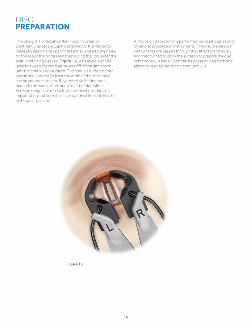
The Straight Tip Radiance Illumination System or Scintillant Disposable Light is attached to the Retractor Blades by placing the tips of the light source into the holes on the top of the blades and then sliding the tips under the built-in retaining sleeves (Figure 13). A Penfield 4 can be used to sweep the residual muscle off of the disc space until the annulus is visualized. The annulus is then incised and an annulotomy (at least the width of the interbody) can be created using the Bayoneted Knife. Undercut, beneath the psoas, more annulus as needed with a Kerrison rongeur which facilitates implant position and implantation and permits easy rotation of implant into the orthogonal position.
A thorough discectomy is performed using pituitaries and other disc preparation instruments. The disc preparation instruments are passed through the retractors obliquely and then turned to allow the surgeon to prepare the disc orthogonally. A large Cobb can be passed along both end plates to release the contralateral annulus.
DISC PREPARATION
Figure 13
25
Helpful HintThe Navigated Clydesdale Spinal System Trials and implants size offering differs from the non-navigated sizes. Refer to the product ordering section in the back of the procedure guide for a list of the available navigated sizes.
Helpful HintKeep in mind that if you are moving bony anatomy, it will not be detected on the StealthStation Monitor.
TRIAL INSERTION
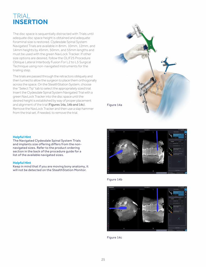
The disc space is sequentially distracted with Trials until adequate disc space height is obtained and adequate foraminal size is restored. Clydesdale Spinal System Navigated Trials are available in 8mm, 10mm, 12mm, and 14mm heights by 45mm, 50mm, and 55mm lengths and must be used with the green NavLock Tracker. If other size options are desired, follow the OLIF25 Procedure Oblique Lateral Interbody Fusion For L2 to L5 Surgical Technique using non-navigated instruments for the trialing step.
The trials are passed through the retractors obliquely and then turned to allow the surgeon to place them orthogonally across the space. On the StealthStation System, choose the “Select Tip” tab to select the appropriately sized trial. Insert the Clydesdale Spinal System Navigated Trial with a green NavLock Tracker into the disc space until the desired height is established by way of proper placement and alignment of the trial (Figures 14a, 14b and 14c). Remove the NavLock Tracker and then use a slap hammer from the trial set, if needed, to remove the trial.
Figure 14b
Figure 14c
Figure 14a
26
NoteInfuse Bone Graft is indicated for spinal fusion procedures in skeletally mature patients with degenerative disc disease (DDD) at one level with certain sizes of Clydesdale Spinal System. See the Clydesdale Surgical Technique for fill guidelines and handling information for Infuse Bone Graft.
BONE GRAFT / INTERBODY PLACEMENT
Before inserting the Clydesdale Spinal System implant, place appropriate bone graft in the implant's central cavity. The Clydesdale implant may be used with Infuse Bone Graft or with autograft and/or allogenic bone graft comprised of cancellous and/or corticocancellous bone graft. Attach the Clydesdale Spinal System implant to the Navigated Inserter. Implant size must be adjusted on the StealthStation to match selected implant. Then, use a mallet to gently insert the implant (Figures 15a, 15b and 15c). The inserter enters obliquely and can then be turned orthogonally across the disc space. The Navigated Inserter is unthreaded from the implant and removed.
After the interbody implant has been inserted into the disc space, the Stability Pin may be unthreaded and removed.
The Retractor is then detached from the Flex Arm and the Retractor Blades are carefully withdrawn from the surgical site. As the Retractor is removed, the muscle and fat layers can be visualized closing back into place.
The surgical site is irrigated appropriately and the fascia over the external oblique is then closed with interrupted synthetic absorbable suture.
Finally, the subcutaneous layers and skin are closed and the skin is sealed with skin adhesive.
CLOSURE
Figure 15b Figure 15c
Figure 15a
Clydesdale Spinal System with Infuse™ Bone Graft
27
Figure 16b
ROD PLACEMENT, COMPRESSION/DISTRACTION, SET SCREW INSERTION
Figure 16a
Infuse Bone Graft is not approved for use in the posterior portion of the spine as a supplement to posterior instrumentation.
Once screws are placed bilaterally (Figures 16a and 16b), see the appropriate CD Horizon Solera Voyager 4.75mm or CD Horizon Solera Voyager 5.5mm Surgical Technique for detailed instructions on rod placement, compression/distraction, and set screw insertion.
If visual confirmation of rod passage is desired prior to the O-arm System confirmation spin, a 2-D fluoroscopy image can be performed using the O-arm System following the guidelines listed in the Image Acquisition section on page 14.
NoteBone graft must be used when implanting the rod/screw construct.
28
CONFIRMATION
Surgical Synergy Spinal Workflow
29
CONFIRMATION IMAGE ACQUISITION
The Reference Frame should be left in place during the confirmation image acquisition to ensure that navigation can still be performed if any changes are required.
With the patient isocenter, position the O-arm System to perform a 3D image acquisition (Figure 17a). During the acquisition process all personnel who are not wearing protective lead apparel should stand at least 15 feet from the O-arm System with a certified moveable lead shield between themselves and the O-arm System to avoid unnecessary radiation exposure. Refer to page 14 for additional details. Perform the image acquisition to confirm screws, rods, and interbody placement (Figure 17b). Following confirmation, the Reference Frame should be removed.
SET SCREW BREAK OFF AND EXTENDED TAB REMOVAL
Set screw break-off, implant tab removal, and instrument removal should be performed per the surgeon's usual manner. See the CD Horizon Solera Voyager 4.75mm or the CD Horizon Solera Voyager 5.5mm Surgical Technique for detailed set screw break-off and tab removal instructions.
CLOSURE
The surgical site is irrigated appropriately and the fascia over the external oblique is closed with interrupted synthetic absorbable suture. Finally, the subcutaneous layers and skin are closed, and the skin is sealed with skin adhesive.
IMPLANT EXPLANTATION
Should it be necessary to remove or reposition the Clydesdale Spinal System device, the Navigated Inserter may be used.
To remove the implant, first fit the tips of the Navigated Inserter with the divots at the end of the implant and thread the inserter into the cage. Finally, attach the Slap Hammer to the Navigated Inserter and gently impact the Slap Hammer to facilitate implant removal.
To remove CD Horizon Solera Voyager 4.75mm or 5.5mm posterior fixation, the appropriate screw driver should be used. For CD Horizon Solera Voyager 4.75mm, the set screws can be removed with the MAS or Non-Retaining Driver. For CD Horizon Solera Voyager 5.5mm, the set screw can be removed with the T27 Removal Driver. Remove the set screw by turning counterclockwise until the set screw is removed. Repeat this step for all set screws. The rod is then removed. Next, either the MAS driver or non-retaining driver can be used to remove the screw by turning counterclockwise until the screw is removed from the pedicle.
Figure 17b
Figure 17a
PRODUCT ORDERINGINFORMATION
OLIF Disc Prep – Disc Access Set
Set Type SPS02845
Part Number DescriptionSet
Quantity
9569650 Bayoneted Penfield #4 1
2942017 XPAK Dilator Holder 1
74-755-000-3325
Suction Tube, 156mm Working Length 1
74-756-000-3325
Suction Tube, 96mm Working Length 1
2940200 Suction Tube, 180mm Working Length 1
9561554 Wide Nerve Root Retractor, Large 1
3280045 Extended Scalpel Holder 1
2940069 Rotating Kerrison, 5mm 1
2940068 Rotating Kerrison, 3mm 1
2942023 Wedge Distractor 14mm 1
9074002 Slap Hammer 1
2143007 Cobb Distractor, 4mm 1
2143006 Cobb Distractor, 6mm 1
3280003 Pituitary Rongeur, 6x14, Upbiting 1
3280001 Pituitary Rongeur, 6x14, Straight 1
PR51468A Pituitary Rongeur, 6mm Angled Down 1
PR51468B Pituitary Rongeur, 6mm, Downbiting 1
74-619-106 Pituitary Rongeur, 6mm, Bayoneted 1
2940076 Pituitary Rongeur, 4mm, Upbiting 1
2940075 Pituitary Rongeur, 4mm 1
907610 Pituitary Rongeur, 8mm 1
OLIF Disc Prep – Endplate Prep Set
Set Type SPS02847
Part Number DescriptionSet
Quantity
2942016 Pull Curettes, 5.5mm, 90 Degrees 1
2942012 Uterine Curette 1
2942020 Osteotome Chisel 1
2942018 Flat Rasp 1
2940050 Combo Tool 1
2940053 Straight Serrated Cup Curette 1
2940056 Ring Curette 1
2143004 OLIF25 Double Sided Uterine Curette
1
2143005 OLIF25 Double Sided Flat Rasp 1
9198260 Straight Bone Graft Tamp 1
OLIF Disc Prep – Cobbs And Shavers Set
Set Type SPS02846
Part Number DescriptionSet
Quantity
2942036 Straight Cobb, 18mm 1
2942035 Straight Cobb, 10mm 1
2143003 OLIF25 Double Sided Cobb, 20mm 1
2941616 Paddle Shaver, 16mm × 45mm 1
2941614 Paddle Shaver, 14mm × 45mm 1
2941612 Paddle Shaver, 12mm × 45mm 1
2941610 Paddle Shaver, 10mm × 45mm 1
2941608 Paddle Shaver, 8mm × 45mm 1
2900165 Cannulated Reamer T-Handle 2
2143009 Angled Box Chisel, 6mm 1
2143008 Angled Box Chisel, 8mm 1
2143010 Angled Box Chisel, 10mm 1
2143012 Angled Box Chisel, 12mm 1
30
SYNERGYOLIF360 SINGLE-POSITIONPRODUCT ORDERING INFORMATION
OLIF25 Access - R Core Set
Set Type SPS02844
Part Number DescriptionSet
Quantity
100SL45529 Anterior Blade, 9cm, SL 1
100SL45531 Anterior Blade, 11cm, SL 1
100SL45533 Anterior Blade, 13cm, SL 1
100SL45535 Anterior Blade, 15cm, SL 1
100SL45537 Anterior Blade, 17cm, SL 1
10045377 Dissection Blade, 17cm 1
100SL60031 Anterior Rack Mount Handle, SL 1
100SL42166 S-Lock to QC Adapter 1
10045817 Radiolucent Holder 1
10042129QL Quick Connect Handle, Lightsource
1
10060013 Rack 85mm with Cephalad/ Caudad Arms
1
10060020 Hex Driver 2
8970400 Stability Pin Driver 1
5107809 Stability Pin, 9 cm 2
5107811 Stability Pin, 11cm 2
5107813 Stability Pin, 13cm 2
5107815 Stability Pin, 15cm 2
5107817 Stability Pin, 17cm 2
OLIF Table Mount + Articulating Arm Set
Set Type SPS02849
Part Number DescriptionSet
Quantity
10041903ACL Rail Clamp 1
10042177 Add-on Arm with Universal Joint 1
FLEX Arm Set
Set Type SPS02850
Part Number DescriptionSet
Quantity
10042165 Quick Connect to Shaft Clamp Adapter 1
10042138Q Flex Arm 1
OLIF25 ACCESS - R Round Blades Set
Set Type SPS02842
Part Number DescriptionSet
Quantity
10045429 Round Cephalad Blade, 9cm 1
10045431 Round Cephalad Blade, 11cm 1
10045433 Round Cephalad Blade, 13cm 1
10045435 Round Cephalad Blade, 15cm 1
10045437 Round Cephalad Blade, 17cm 1
10045449 Round Caudad Blade, 9cm 1
10045451 Round Caudad Blade, 11cm 1
10045453 Round Caudad Blade, 13cm 1
10045455 Round Caudad Blade, 15cm 1
10045457 Round Caudad Blade, 17cm 1
10045840 OLIF Solid First Dilator, 5mm 1
9560420 METRX, Dilator 5.3mm 1
9561421 Dilator, 10.6mm 1
9561422 Dilator, 16mm 1
9561424 Dilator, 20.8mm 1
75700450 Guidewire, Blunt, 450mm 1
75700350 Guidewire, Blunt, 350mm 1
8670002 Guidewire, Sharp, 450mm 1
8670005 Guidewire, Sharp, 350mm 1
OLIF25 ACCESS - R Flat Blades Set
Set Type SPS02843
Part Number DescriptionSet
Quantity
10045489 Flat Cephalad Blade, 9cm 1
10045491 Flat Cephalad Blade, 11cm 1
10045493 Flat Cephalad Blade, 13cm 1
10045495 Flat Cephalad Blade, 15cm 1
10045497 Flat Cephalad Blade, 17cm 1
10045509 Flat Caudad Blade, 9cm 1
10045511 Flat Caudad Blade, 11cm 1
10045513 Flat Caudad Blade, 13cm 1
10045515 Flat Caudad Blade, 15cm 1
10045517 Flat Caudad Blade, 17cm 1
10045841 Flat Blade Dilator, 18mm, Clover 1
10060030 Flat Blade Dilator, 18mm, Smooth
1
75700450 Guidewire, Blunt, 450mm 1
75700350 Guidewire, Blunt, 350mm 1
8670002 Guidewire, Sharp, 450mm 1
8670005 Guidewire, Sharp, 350mm 1
31
SYNERGYOLIF360 SINGLE-POSITIONPRODUCT ORDERING INFORMATION
OLIF Disc Prep Support Set
Set Type SPS02874
Part Number Description Qty
1850077 Double Generic Outer Case 1
1850079 Generic Outer Lid 1
2159012 OLIF Disc Prep - Support Set Top Tray 1
2159013 OLIF Disc Prep - Support Set Bottom Tray 1
2159014 OLIF Disc Prep - Support Outer Case Label 2
2940051 Angled Combo Tool 1
2940052 Reverse Angled Combo Tool 1
2940054 Angled Serrated Cup Curette 1
2940057 Cobb Elevator, 10mm 1
2940059 Cobb Elevator, 18mm 1
2942014 Size 5, 90 Degree Push Curette 1
2942015 Size 5.5, 45 Degree Cup Curette 1
2942019 Curved Rasp 1
2942026 8mm Rotate Distractor 1
2942028 10mm Rotate Distractor 1
2942030 12mm Rotate Distractor 1
2942032 14mm Rotate Distractor 1
2942037 10mm Endplate Protector 2
2942058 18mm Endplate Protector 2
3280010 Rake Curette, Angled 1
3280018 Size 1, Cup Curette, Angled 1
3280019 Size 5, Reverse Curette, 90 Degree 1
3280041 12mm × 20mm Rasp, 20 Degree 1
3280044 Bone Graft Tamp, 6mm 1
Clydesdale Trials
Part Number Description Qty
9734653 8mm × 45mm Clydesdale Trial 1
9734654 8mm × 50mm Clydesdale Trial 1
9734655 8mm × 55mm Clydesdale Trial 1
9734656 10mm × 45mm Clydesdale Trial 1
9734657 10mm × 50mm Clydesdale Trial 1
9734658 10mm × 55mm Clydesdale Trial 1
9734659 12mm × 45mm Clydesdale Trial 1
9734660 12mm × 50mm Clydesdale Trial 1
9734661 12mm × 55mm Clydesdale Trial 1
9734662 14mm × 45mm Clydesdale Trial 1
9734663 14mm × 50mm Clydesdale Trial 1
9734664 14mm × 55mm Clydesdale Trial 1
9734694 Clydesdale Trials Set Container 1
OLIF/DLIF Disposable Suitcase
Set Type SPS00589
Part Number Description Qty
1563-00 Bayonetted Knife 1
1590-00 Bayonet Bipolar Forceps, 190mm 1
1590-01 Straight Tip Bayonet Bipolar Forceps 1
9450015 NIM-Spine 23cm Ball Tip Probe 1
9450069 NIM-Spine Pedicle Asscess Long Probe 1
945NSD2750 Direct Lateral Dilators /Stim DLIF Dilators
1
945NRE1003 Electroe SD Needle Recording 1
9560658 Quadrant Illumination System 1
9560668 Straight Tip Radiance Illumination System
1
2762-01-0004 Straight Tip OLIF Light Source 2
9561003 Suitcase 1
Navigated Lateral Disc Prep Instruments
Set Type SPS02868
Part Number Description Qty
1850076 Single Generic Outer Case 1
1850079 Generic Outer Lid 1
G900100 Quarter-Inch Quick-Connect T-Handle
1
NAV2066 NAV 10mm Straight Cobb 1
NAV2067 NAV 18mm Straight Cobb 1
NAV2068 NAV Combo Tool 1
NAV2069 NAV Uterine Curette 1
NAV2070 NAV Straight Lateral Ostetome 1
NAV2071 NAV Lateral Rotating Shaver, 8mm 1
NAV2072 NAV Lateral Rotating Shaver, 10mm 1
NAV2073 NAV Lateral Rotating Shaver, 12mm 1
NAV2074 NAV Lateral Rotating Shaver, 14mm 1
NAV2092 NAV Lateral Disc Prep Tray 1
NAV2093 NAV Lateral Disc Prep Outer Case Label
2
TLIF/DLIF Inserter Set
9734836
Part Number Description Qty
9734456 Capstone and Clydesdale Inserter 1
9734592 Slap Hammer 1
9734695 TLIF / DLIF Inserter Set Container 1
32
SYNERGYOLIF360 SINGLE-POSITIONPRODUCT ORDERING INFORMATION
33
CD Horizon Solera Voyager4.75 Screw & Instrument Set
Set Type SPS02695
Part Number Description Qty
54850014535 4.75 Solera Voyager, MAS 4.5 × 35cc 4
54850014540 4.75 Solera Voyager, MAS 4.5 × 40cc 4
54850014545 4.75 Solera Voyager, MAS 4.5 × 45cc 4
54850015535 4.75 Solera Voyager, MAS 5.5 × 35cc 6
54850015540 4.75 Solera Voyager, MAS 5.5 × 40cc 8
54850015545 4.75 Solera Voyager, MAS 5.5 × 45cc 8
54850015550 4.75 Solera Voyager, MAS 5.5 × 50cc 6
54850016535 4.75 Solera Voyager, MAS 6.5 × 35cc 6
54850016540 4.75 Solera Voyager, MAS 6.5 × 40cc 8
54850016545 4.75 Solera Voyager, MAS 6.5 × 45cc 8
54850016550 4.75 Solera Voyager, MAS 6.5 × 50cc 8
54850016555 4.75 Solera Voyager, MAS 6.5 × 55cc 6
54850017535 4.75 Solera Voyager, MAS 7.5 × 35cc 6
54850017540 4.75 Solera Voyager, MAS 7.5 × 40cc 6
54850017545 4.75 Solera Voyager, MAS 7.5 × 45cc 6
54850017550 4.75 Solera Voyager, MAS 7.5 × 50cc 4
54850017555 4.75 Solera Voyager, MAS 7.5 × 55cc 4
5584007 Screw Gauge 1
6642012 Break-off Removal Tool 1
6642006 Tab Extender Cap 10
6642007 Tab Extender 18
5484845 4.5 Cannulated Tap 1
5484855 5.5 Cannulated Tap 1
5484865 6.5 Cannulated Tap 1
5484875 7.5 Cannulated Tap 1
5484885 4.5-5.5mm Self Drilling Tap 1
5484887 5.5-6.5mm Self Drilling Tap 1
CD Horizon Solera Voyager 4.75 Percutaneous Rods and Instruments
Set Type SPS02696
Part Number Description Qty
9010000849 Perc Inserter 2
641000030 30mm Perc Rod, 4.75mm CCM 4
641000035 35mm Perc Rod, 4.75mm CCM 4
641000040 40mm Perc Rod, 4.75mm CCM 4
641000045 45mm Perc Rod, 4.75mm CCM 4
641000050 50mm Perc Rod, 4.75mm CCM 4
641000055 55mm Perc Rod, 4.75mm CCM 4
641000060 60mm Perc Rod, 4.75mm CCM 4
641000065 65mm Perc Rod, 4.75mm CCM 4
641000070 70mm Perc Rod, 4.75mm CCM 4
641000075 75mm Perc Rod, 4.75mm CCM 4
641000080 80mm Perc Rod, 4.75mm CCM 4
641000085 85mm Perc Rod, 4.75mm CCM 4
641000090 90mm Perc Rod, 4.75mm CCM 4
6440530 4.75 Solera PERC Set Screw Ti 12
CD Horizon Solera Voyager 4.75mm Universal Instruments
Set Type SPS02694
Part Number Description Qty
6640008 4.75 MAS Screwdriver 2
6640005 4.75 Non-Retaining Screwdriver 1
6640004 4.75 Ball-Ended Driver 1
6642014 One-step Inner Dilator 1
6642015 One-step Small Outer Dilator 1
6642010 Rod Confirmation Tool 1
7579000 Q/C Ratcheting T-Handle 1
9098120 Cannulated Ratcheting Egg Handle 2
6642000 Compressor/Distractor A 1
6642001 Compressor/Distractor B 1
6642017 Pliers Compressor 1
6642002 4.75 Set Screw Retaining Driver 2
6642004 Countertorque 1
6642013 Tab Breaker 1
6642008 Rod Pusher 1
6642011 Rod Template 1
8670001 Guidewire, Blunt 6
8670002 Guidewire, Sharp 6
815-518 T25 Removal Driver 1
7570090 T-Handle 1
34
OPTIONAL SET
CD Horizon Solera Voyager 4.75mm Capped Rod and Instrument Set
Set Type SPS02697
Part Number Description Qty
6642009 Rod Gripper 1
641003030 30mm Capped Rod, 4.75mm CCM 3
641003035 35mm Capped Rod, 4.75mm CCM 3
641003040 40mm Capped Rod, 4.75mm CCM 3
641003045 45mm Capped Rod, 4.75mm CCM 3
641003050 50mm Capped Rod, 4.75mm CCM 3
641003055 55mm Capped Rod, 4.75mm CCM 3
641003060 60mm Capped Rod, 4.75mm CCM 3
641003065 65mm Capped Rod, 4.75mm CCM 3
641003070 70mm Capped Rod, 4.75mm CCM 3
641003075 75mm Capped Rod, 4.75mm CCM 3
641003080 80mm Capped Rod, 4.75mm CCM 3
6440530 4.75 Solera™ Perc Set Screw Ti 10
CD Horizon Solera Voyager 4.75 ATS Streamlined Instruments
Set Type SPS02930
Part Number Description Qty
6642006 4.75mm Voyager Extender Cap 10
6642007 Tab Extender 18
6642012 Break-off Removal tool 4.75 1
5584007 Screw Gauge 1
CD Horizon Solera Voyager 4.75 ATS Implants
Set Type SPS02911
Part Number Description Qty
54850044530 Solera Voyager 4.75 ATS 4.5 × 30 4
54850044535 Solera Voyager 4.75 ATS 4.5 × 35 4
54850044540 Solera Voyager 4.75 ATS 4.5 × 40 4
54850045530 Solera Voyager 4.75 ATS 5.5 × 30 4
54850045535 Solera Voyager 4.75 ATS 5.5 × 35 6
54850045540 Solera Voyager 4.75 ATS 5.5 × 40 8
54850045545 Solera Voyager 4.75 ATS 5.5 × 45 8
54850045550 Solera Voyager 4.75 ATS 5.5 × 50 6
54850046530 Solera Voyager 4.75 ATS 6.5 × 30 4
54850046535 Solera Voyager 4.75 ATS 6.5 × 35 6
54850046540 Solera Voyager 4.75 ATS 6.5 × 40 8
54850046545 Solera Voyager 4.75 ATS 6.5 × 45 8
54850046550 Solera Voyager 4.75 ATS 6.5 × 50 8
54850047535 Solera Voyager 4.75 ATS 7.5 × 35 6
54850047540 Solera Voyager 4.75 ATS 7.5 × 40 6
54850047545 Solera Voyager 4.75 ATS 7.5 × 45 6
54850047550 Solera Voyager 4.75 ATS 7.5 × 50 6
54850047555 Solera Voyager 4.75 ATS 7.5 × 55 4
NAV6640009 Solera Voyager 4.75 NAV Driver 2
SYNERGYOLIF360 SINGLE-POSITIONPRODUCT ORDERING INFORMATION
35
CD Horizon Solera Voyager 5.5/6.0mm Cannulated Multi-Axial Screw and Instrument Set
Set Type SPS02887
Part Number Description Qty
55850014535 4.5mm × 35mm Cannulated MAS 4
55850014540 4.5mm × 40mm Cannulated MAS 4
55850014545 4.5mm × 45mm Cannulated MAS 4
55850015535 5.5mm × 35mm Cannulated MAS 6
55850015540 5.5mm × 40mm Cannulated MAS 8
55850015545 5.5mm × 45mm Cannulated MAS 8
55850015550 5.5mm × 50mm Cannulated MAS 6
55850016535 6.5mm × 35mm Cannulated MAS 6
55850016540 6.5mm × 40mm Cannulated MAS 8
55850016545 6.5mm × 45mm Cannulated MAS 8
55850016550 6.5mm × 50mm Cannulated MAS 8
55850016555 6.5mm × 55mm Cannulated MAS 6
55850017535 7.5mm × 35mm Cannulated MAS 6
55850017540 7.5mm × 40mm Cannulated MAS 6
55850017545 7.5mm × 45mm Cannulated MAS 6
55850017550 7.5mm × 50mm Cannulated MAS 4
55850017555 7.5mm × 55mm Cannulated MAS 4
5584007 Screw Gauge 1
6551004 4.5mm One-Step Tap 1
6551005 5.5mm One-Step Tap 1
6551006 6.5mm One-Step Tap 1
6551007 7.5mm One-Step Tap 1
6551045 4.5-5.5mm One-Step Drill Tap 1
6551056 5.5-6.5mm One-Step Drill Tap 1
6550000 Tap Sleeve 1
CD Horizon Solera Voyager 5.5/6.0mm Large Diameter Screw Kit
CD Horizon Solera Voyager 5.5/6.0mm Capped Rods and Instruments
Set Type SPS02889
Part Number Description Qty
6550014 Rod Gripper 1
651003030 5.5mm Cobalt Chrome Capped Rod, 30mm 3
651003035 5.5mm Cobalt Chrome Capped Rod, 35mm 3
651003040 5.5mm Cobalt Chrome Capped Rod, 40mm 3
651003045 5.5mm Cobalt Chrome Capped Rod, 45mm 3
651003050 5.5mm Cobalt Chrome Capped Rod, 50mm 3
651003055 5.5mm Cobalt Chrome Capped Rod, 55mm 3
651003060 5.5mm Cobalt Chrome Capped Rod, 60mm 3
651003065 5.5mm Cobalt Chrome Capped Rod, 65mm 3
651003070 5.5mm Cobalt Chrome Capped Rod, 70mm 3
651003075 5.5mm Cobalt Chrome Capped Rod, 75mm 3
651003080 5.5mm Cobalt Chrome Capped Rod, 80mm 3
NoteCD Horizon Solera Voyager 5.5/6.0mm Screws will accept either a 5.5mm or a 6.0mm Rod. 6.0mm Rods are not available in the set. They must be ordered separately as a custom item.
SYNERGYOLIF360 SINGLE-POSITIONPRODUCT ORDERING INFORMATION
37
CD Horizon Solera Voyager 5.5/6.0mm Longer Percutaneous Rods
CD Horizon Solera Voyager 5.5/6.0mm Universal Instruments
Set Type SPS02894
Part Number Description Qty
6550027 5.5/6.0mm Threaded Rod Reducer 2
6550031 5.5/6.0mm Nut Driver 2
6550009 5.5/6.0mm Plier Compressor 1
6550034 5.5/6.0mm Reinforcement Sleeve 2
6550035 5.5/6.0mm Fulcrum Pliers 1
6550036 5.5/6.0mm Fulcrum 17480162 French Bender 1
Navigated CD Horizon Solera Complete Percutaneous Taps/Drivers Set
Set Type SPS02829
Part Number Description
NAV2002 Solera Awl Tip Tap 4.5mm
NAV2004 Solera Awl Tip Tap 5.5mm
NAV2006 Solera Awl Tip Tap 6.5mm
NAV2008 Solera Awl Tip Tap 7.5mm
NAV2015 Solera Awl Tip Tap 4.5-5.5mm
NAV2016 Solera Awl Tip Tap 5.5-6.5mm
NAV2017 Solera Awl Tip Tap Small Dilator
NAV2018 Solera Awl Tip Tap Large Dilator
NAV2020 Solera 5.5/6.0 MAS Lg2 Driver
NAV2022 Solera 5.5/6.0 FAS/SAS Lg2 Driver
NAV2023 Solera 4.75 MAS Lg2 Driver
NAV2024 Solera 4.75 Standard MAS Driver
NAV2025 Solera 4.75 Reduct MAS Driver
NAV6550005 Solera Voyager 5.5/6.0 Nav MAS Driver
NAV6640009 Solera Voyager 4.75 Nav MAS Driver
BRIEF SUMMARY
BRIEF SUMMARY OF INDICATIONS, CONTRAINDICATIONS, AND WARNINGS FOR:Infuse™ Bone Graft/LT-Cage™ Lumbar Tapered Fusion DeviceInfuse™ Bone Graft/Inter Fix™ Threaded Fusion DeviceInfuse™ Bone Graft/Inter Fix™ RP Threaded Fusion DeviceInfuse™ Bone Graft/Perimeter™ Interbody Fusion DeviceInfuse™ Bone Graft/Clydesdale™ Spinal SystemInfuse™ Bone Graft/Divergence-L™ Anterior/Oblique Lumbar Fusion SystemInfuse™ Bone Graft/Pivox™ Oblique Lateral Spinal System
The Infuse™ Bone Graft/Medtronic Interbody Fusion Device is indicated for spinal fusion procedures in skeletally mature patients with degenerative disc disease (DDD) at one level from L2-S1, who may also have up to Grade I spondylolisthesis or Grade 1 retrolisthesis at the involved level.
The following interbody devices and surgical approaches may be used with Infuse™ Bone Graft:
§ The LT-Cage™ Lumbar Tapered Fusion Device, implanted via an anterior open or an anterior laparoscopic approach at a single level.
§ The Inter Fix™ or Inter Fix™ RP Threaded Fusion Device, implanted via an anterior open approach at a single level.
§ The Perimeter™ Interbody Fusion Device implanted via a retroperitoneal anterior lumbar interbody fusion (ALIF) at a single level from L2-S1 or an oblique lateral interbody fusion (OLIF) approach at a single level from L5-S1.
§ The Clydesdale™ Spinal System, implanted via an OLIF approach at a single level from L2-L5.
§ The Divergence-L™ Anterior/Oblique Lumbar Fusion System interbody device implanted via an ALIF approach at a single level from L2-S1 or an OLIF approach at a single level from L5-S1.
§ The Pivox™ Oblique Lateral Spinal System implanted via an OLIF approach at a single-level from L2-L5.
The Infuse™ Bone Graft/Medtronic Interbody Fusion Device consists of two components containing three parts – a spinal fusion cage, a recombinant human bone morphogenetic protein, and a carrier/scaffold for the bone morphogenetic protein and resulting bone. These components must be used as a system for the prescribed indication described above. The bone morphogenetic protein solution component must not be used without the carrier/scaffold component or with a carrier/scaffold component different from the one described in this document. The Infuse™ Bone Graft component must not be used without the Medtronic Interbody Fusion Device component.
NOTE: The Inter Fix™ Threaded Fusion Device and the Inter Fix™ RP Threaded Fusion Device may be used together to treat a spinal level. The LT-Cage™ Lumbar Tapered Fusion Device, the Perimeter™ Interbody Fusion Device, the Clydesdale™ Spinal System, the Divergence-L™ Anterior/Oblique Lumbar Fusion System, and the Pivox™ Oblique Lateral Spinal System implants are not to be used in conjunction with either the Inter Fix™ OR Inter Fix™ RP implants to treat a spinal level.
The Infuse™ Bone Graft/Medtronic Interbody Fusion Device is contraindicated for patients with a known hypersensitivity to recombinant human Bone Morphogenetic Protein-2, bovine Type I collagen, or to other components of the formulation and should not be used in the vicinity of a resected or extant tumor, in patients with any active malignancy, or patients undergoing treatment for a malignancy; in patients who are skeletally immature; in pregnant women; or in patients with an active infection at the operative site or with an allergy to titanium, titanium alloy, or polyetheretherketone (PEEK).
There are no adequate and well-controlled studies in human pregnant women. In an experimental rabbit study, rhBMP-2 has been shown to elicit antibodies that are capable of crossing the placenta. Women of child bearing potential should be warned by their surgeon of potential risk to a fetus and informed of other possible orthopedic treatments. The safety and effectiveness of this device has not been established in nursing mothers. Women of child- bearing potential should be advised to not become pregnant for one year following treatment with this device.
Please see the Infuse™ Bone Graft package insert for the complete list of indications, warnings, precautions, adverse events, clinical results, definition of DDD, and other important medical information. The package insert also matches the sizes of those sized devices that are indicated for use with the appropriate Infuse™ Bone Graft kit. An electronic version of the package insert may be found at www.medtronic.com/manuals.
CAUTION: Federal (USA) law restricts this device to sale by or on the order of a physician with appropriate training or experience.
38
SYNERGYOLIF360 SINGLE-POSITIONBRIEF SUMMARY
Important Information On Clydesdale® Spinal SystemPurposeThis device is a PEEK (Polyetheretherketone) interbody fusion device intended for stabilization use and to promote bone fusion during the normal healing process following surgical correction of disorders of the spine. The product should be implanted only by a physician who is thoroughly knowledgeable in the implant's material and surgical aspects and who has been instructed as to its mechanical and material applications and limitations.
DescriptionThe Clydesdale® Spinal System consists of PEEK cages of various widths and heights, which include Tantalum markers. These devices can be inserted between two lumbar or lumbosacral vertebral bodies to give support and correction during lumbar interbody fusion surgeries. The hollow geometry of the implants allows them to be packed with autogenous bone graft and/or allogenic bone graft comprised of cancellous and/or corticocancellous bone, or Infuse® Bone Graft as designated below.
Implied warranties of merchantability and fitness for a particular purpose or use are specifically excluded.
IndicationsThe Clydesdale® Spinal System is intended to be used in interbody fusion procedures for patients diagnosed with Degenerative Disc Disease (DDD) at one or two contiguous levels from L2 to S1. DDD patients may also have up to Grade 1 Spondylolisthesis or retrolisthesis at the involved levels. DDD is defined as discogenic back pain with degeneration of the disc confirmed by history and radiographic studies. When used for these indications, the Clydesdale® Spinal System is intended for use with supplemental fixation systems cleared for use in the lumbar spine.
Certain sizes of the Clydesdale® Spinal System may be used with Infuse® Bone Graft in single-level Oblique Lateral Interbody Fusion (OLIF) procedures from L2 to L5 in patients diagnosed with DDD, as defined above. Consult the labeling for the Infuse® Bone Graft/Medtronic Interbody Fusion Device for information on the specific sizes of the Clydesdale® Spinal System approved for use with Infuse® Bone Graft, as well as specific information regarding contraindications, warnings, and precautions associated with Infuse® Bone Graft. Infuse® Bone Graft is not indicated for use in a direct lateral interbody fusion (DLIF) surgical approach.
Additionally, the Clydesdale® Spinal System can be used to provide anterior column support in patients diagnosed with degenerative scoliosis as an adjunct to pedicle screw fixation. Infuse® Bone Graft is not indicated for use in patients with this condition.
These patients should be skeletally mature and have had six months of nonoperative treatment. The Clydesdale® Spinal System is intended to be used with autograft and/or allogenic bone graft comprised of cancellous and/or corticocancellous bone graft when the subject device is used as an adjunct to fusion. These implants may be implanted via a minimally invasive lateral approach.
ContraindicationsThis device is not intended for cervical spine use. Contraindications include, but are not limited to:
§ Infection local to the operative site.
§ Signs of local inflammation.
§ Fever or leukocytosis.
§ Morbid obesity.
§ Pregnancy.
§ Mental illness.
§ Any other condition which would preclude the potential benefit of spinal implant surgery, such as the presence of tumors or congenital abnormalities, fracture local to the operating site, elevation of sedimentation rate unexplained by other diseases, elevation of white blood count (WBC), or a marked left shift in the WBC differential count.
§ Suspected or documented allergy or intolerance to composite materials.
§ Any case not needing a fusion.
§ Any case not described in the indications.
§ Any patient unwilling to cooperate with postoperative instructions.
§ Patients with a known hereditary or acquired bone friability or calcification problem.
§ Pediatric cases or where the patient still has general skeletal growth.
§ Spondylolisthesis unable to be reduced to Grade 1.
§ Any case where the implant components selected for use would be too large or too small to achieve a successful result.
§ Any case that requires the mixing of metals from two different components or systems.
§ Any patient having inadequate tissue coverage over the operative site or inadequate bone stock or quality.
§ Any patient in which implant utilization would interfere with anatomical structures or expected physiological performance.
§ Prior fusion at the level to be treated.
Nota Bene: Although not absolute contraindications, conditions to be considered as potential factors for not using this device include:
§ Severe bone resorption
§ Osteomalacia
§ Severe osteoporosis
POTENTIAL ADVERSE EVENTSAdverse effects may occur when the device is used either with or without associated instrumentation. The potential risk of adverse effects as a result of movement and non-stabilization may increase in cases where associated complementary support is not employed. Potential adverse events include but are not limited to:
§ Implant migration.
§ Breakage of the device(s).
§ Foreign body reaction to the implants including possible tumor formation, auto immune disease, and/or scarring.
§ Pressure on the surrounding tissues or organs.
§ Damage to the peritoneum.
§ Loss of proper spinal curvature, correction, height, and/or reduction.
§ Infection.
§ Bone fracture or stress shielding at, above, or below the level of surgery.
§ Non-union (or pseudoarthrosis).
§ Loss of neurological function, appearance of radiculopathy, dural tears, and/or development of pain.
§ Neurovascular compromise including paralysis, temporary or permanent retrograde ejaculation in males, or other types of serious injury.
§ Cerebral spinal fluid leakage.
§ Hemorrhage of blood vessels and/or hematomas.
§ Damage to the anterior vasculature.
§ Discitis, arachnoiditis, and/or other types of inflammation.
§ Deep venous thrombosis, thrombophlebitis, and/or pulmonary embolus.
§ Bone graft donor site complication.
§ Inability to resume activities of normal daily living.
§ Early or late loosening or movement of the device(s).
§ Urinary retention or loss of bladder control or other types of urological system compromise.
39
SYNERGYOLIF360 SINGLE-POSITIONBRIEF SUMMARY
§ Scar formation possibly causing neurological compromise or compression around nerves and/or pain.
§ Fracture, microfracture, resorption, damage, or penetration of any spinal bone (including the sacrum, pedicles, and/or vertebral body) and/or bone graft or bone graft harvest site at, above, and/or below the level of surgery.
§ Retropulsed graft.
§ Herniated nucleus pulposus, disc disruption, or degeneration at, above, or below the level of surgery.
§ Loss of or increase in spinal mobility or function.
§ Reproductive system compromise including sterility, loss of consortium, and sexual dysfunction.
§ Development of respiratory problems (e.g., pulmonary embolism, atelectasis, bronchitis, pneumonia, etc.).
§ Change in mental status.
§ Cessation of any potential growth of the operated portion of the spine.
§ Death.
WARNINGS AND PRECAUTIONSWarning: When used in deformity procedures, undersizing the implant may limit endplate engagement and potentially lead to implant migration and/or expulsion.
A successful result is not always achieved in every surgical case. This fact is especially true in spinal surgery where other patient conditions may compromise the results. Use of this product without bone graft or in cases that do not develop a union will not be successful.
Preoperative and operating procedures, including knowledge of surgical techniques, good reduction, and correct selection and placement of the implants are important considerations in the successful utilization of the system by the surgeon. Further, the proper selection and the compliance of the patient will greatly affect the results. Patients who smoke have been shown to have a reduced incidence of bone fusion. These patients should be advised of this fact and warned of this consequence. Obese, malnourished, and/or alcohol/drug abuse patients and those with poor muscle and bone quality and/or nerve paralysis are also poor candidates for spinal fusion.
Patients with previous spinal surgery at the levels to be treated may have different clinical outcomes compared to those with a previous surgery.
A device that has been implanted should never be reused, reprocessed, or resterilized under any circumstances. Sterile packaged devices should also never be resterilized. Reuse, reprocessing, or resterilization may compromise the structural integrity of these implants and create a risk of contamination of the implants which could result in patient injury, illness, or death.
Physician Note: Although the physician is the learned intermediary between the company and the patient, the important medical information given in this document should be conveyed to the patient.
FOR US AUDIENCES ONLY
Caution: Federal law (USA) restricts these devices to sale by or on the order of a physician.
40
41
PURPOSEThe CD HORIZON Spinal System is intended to help provide immobilization and stabilization of spinal segments as an adjunct to fusion of the thoracic, lumbar, and/or sacral spine.
DESCRIPTIONThe CD HORIZON™ Spinal System consists of a variety of shapes and sizes of rods, hooks, screws, CROSSLINK™ Plates, staples and connecting components, as well as implant components from other Medtronic spinal systems, which can be rigidly locked into a variety of configurations, with each construct being tailor-made for the individual case.
A subset of CD HORIZON™ Spinal System components may be used for posterior pedicle screw fixation in pediatric cases. These constructs may be comprised of a variety of shapes and sizes of rods (ranging in diameter from 3.5mm to 6.35mm), hooks, screws, CROSSLINK™ Plates, and connecting components. Similarly to the CD HORIZON™ implants used in adult cases, these components can be rigidly locked into a variety of configurations, with each construct being tailor-made for the individual case.
Certain components within the CD HORIZON™ Spinal System are specifically excluded for use in pediatric patients. These include PEEK rods, Shape Memory Alloy Staples, SPIRE™ Plates and DYNALOK bolts. All screws used in pediatric cases are only cleared for use via a posterior approach. All of the components used in pediatric cases are fabricated from medical grade stainless steel, medical grade titanium, titanium alloy, and medical grade cobalt-chromium-molybdenum alloy.
Certain implant components from other Medtronic spinal systems can be used with the CD HORIZON™ Spinal System in non-pediatric cases. These components include TSRH™ rods, hooks, screws, plates, CROSSLINK™ plates, connectors, staples, washers, GDLH rods, hooks, connectors and CROSSLINK™ bar and connectors; LIBERTY rods and screws; DYNALOK PLUS and DYNALOK CLASSIC bolts along with rod/bolt connectors; and Medtronic Multi-Axial rods and screws. Please note that certain components are specifically designed to connect to specific rod diameters, while other components can connect to multiple rod diameters. Care should be taken so that the correct components are used in the spinal construct.
CD HORIZON™ hooks are intended for posterior use only. CD HORIZON™ staples and CD HORIZON™ ECLIPSE™ rods and associated screws are intended for anterior use only. However, for patients of smaller stature and pediatric patients, CD HORIZON™4.5mm rods and associated components may be used posteriorly.
The CD HORIZON™ Spinal System implant components are fabricated from medical grade stainless steel, medical grade titanium, titanium alloy, medical grade cobalt-chromium-molybdenum alloy, or medical grade PEEK OPTIMA-LT1. Certain CD HORIZON™ Spinal System components may be coated with hydroxyapatite. No warranties expressed or implied are made. Implied warranties of merchantability and fitness for a particular purpose or use are specifically excluded. See the MDT Catalog for further information about warranties and limitations of liability.
Never use stainless steel and titanium implant components in the same construct.
Medical grade titanium, titanium alloy, and/or medical grade cobalt-chromium-molybdenum alloy may be used together. Never use titanium, titanium alloy, and/or medical grade cobalt-chromium-molybdenum alloy with stainless steel in the same construct.
The CD HORIZON™ Spinal System also includes anterior staples made of Shape Memory Alloy (Nitinol – NiTi). Shape Memory Alloy is compatible with titanium, titanium alloy, and cobalt-chromium-molybdenum alloy. Do not use with stainless steel. These staples are not to be used in pediatric patients.
PEEK OPTIMA-LT1 implants may be used with stainless steel, titanium, or cobalt-chromium-molybdenum alloy implants. CD HORIZON™ PEEK Rods are not to be used with CROSSLINK™ Plates or in pediatric patients.
To achieve best results, do not use any of the CD HORIZON™ Spinal System implant components with components from any other system or manufacturer unless specifically allowed to do so in this or another Medtronic document. As with all orthopaedic and neurosurgical implants, none of the CD HORIZON™ Spinal System components should ever be reused under any circumstances.
INDICATIONSThe CD HORIZON™ Spinal System with or without SEXTANT™ instrumentation is intended for posterior, non-cervical fixation as an adjunct to fusion for the following indications: degenerative disc disease (defined as back pain of discogenic origin with degeneration of the disc confirmed by history and radiographic studies), spondylolisthesis, trauma (i.e., fracture or dislocation), spinal stenosis, curvatures (i.e., scoliosis, kyphosis, or lordosis), tumor, pseudarthrosis, and/or failed previous fusion.
Except for hooks, when used as an anterolateral thoracic/lumbar system, the CD HORIZON™ Spinal System may also be used for the same indications as an adjunct to fusion.
With the exception of degenerative disc disease, the CD HORIZON™ LEGACY™ 3.5mm rods and the CD HORIZON™ Spinal System PEEK rods and associated components may be used for the aforementioned indications in skeletally mature patients as an adjunct to fusion. The 3.5mm rods may be used for the specific pediatric indications noted below.
When used for posterior non-cervical pedicle screw fixation in pediatric patients, the CD HORIZON™ Spinal System implants are indicated as an adjunct to fusion to treat progressive spinal deformities (i.e., scoliosis, kyphosis, or lordosis) including idiopathic scoliosis, neuromuscular scoliosis, and congenital scoliosis. Additionally, the CD HORIZON™ Spinal System is intended to treat pediatric patients diagnosed with the following conditions: spondylolisthesis/spondylolysis, fracture caused by tumor and/or trauma, pseudarthrosis, and/or failed previous fusion. These devices are to be used with autograft and/or allograft. Pediatric pedicle screw fixation is limited to a posterior approach.
The CD HORIZON™ SPIRE™ Plate is a posterior, single-level, non-pedicle supplemental fixation device intended for use in the non-cervical spine (T1-S1) as an adjunct to fusion in skeletally mature patients. It is intended for plate fixation/attachment to spinous processes for the purpose of achieving supplemental fixation in the following conditions: degenerative disc disease (as previously defined), spondylolisthesis, trauma, and/or tumor.
In order to achieve additional levels of fixation, the CD HORIZON™ Spinal System rods may be connected to the VERTEX™ Reconstruction System with the VERTEX™ rod connector. Refer to the VERTEX™ Reconstruction System Package Insert for a list of the VERTEX™ indications of use.
CONTRAINDICATIONSContraindications include, but are not limited to:
§ Active infectious process or significant risk of infection (immunocompromise).
§ Signs of local inflammation.
§ Fever or leukocytosis.
§ Morbid obesity.
§ Pregnancy.
§ Mental illness.
§ Grossly distorted anatomy caused by congenital abnormalities.
IMPORTANT PRODUCT INFORMATION ON THE CD HORIZON™ SPINAL SYSTEM
42
§ Any other medical or surgical condition which would preclude the potential benefit of spinal implant surgery, such as the presence of congenital abnormalities, elevation of sedimentation rate unexplained by other diseases, elevation of white blood count (WBC), or a marked left shift in the WBC differential count.
§ Suspected or documented metal allergy or intolerance.
§ Any case not needing a bone graft and fusion.
§ Any case where the implant components selected for use would be too large or too small to achieve a successful result.
§ Any patient having inadequate tissue coverage over the operative site or inadequate bone stock or quality.
§ Any patient in which implant utilization would interfere with anatomical structures or expected physiological performance.
§ The CD HORIZON™ SPIRE™ Plate and the CD HORIZON™ PEEK Rods are specifically contraindicated for use in pediatric patients.
§ Any patient unwilling to follow postoperative instructions.
§ Any case not described in the indications.
NOTA BENE: Although not absolute contraindications, conditions to be considered as potential factors for not using this device include:
§ Severe bone resorption.
§ Osteomalacia
§ Severe osteoporosis.
POTENTIAL ADVERSE EVENTSAll of the possible adverse events associated with spinal fusion surgery without instrumentation are possible. With instrumentation, a listing of potential adverse events includes, but is not limited to:
§ Early or late loosening of any or all of the components.
§ Disassembly, bending, and/or breakage of any or all of the components.
§ Foreign body (allergic) reaction to implants, debris, corrosion products (from crevice, fretting, and/or general corrosion), including metallosis, staining, tumor formation, and/or autoimmune disease.
§ Pressure on the skin from component parts in patients with inadequate tissue coverage over the implant possibly causing skin penetration, irritation, fibrosis, neurosis, and/or pain.
§ Bursitis.
§ Tissue or nerve damage caused by improper positioning and placement of implants or instruments.
§ Post-operative change in spinal curvature, loss of correction, height, and/or reduction.
§ Loss of neurological function (e.g., sensory and/or motor), including paralysis (complete or incomplete), dysesthesias, hyperesthesia, anesthesia, paresthesia, appearance of radiculopathy, and/or the development or continuation of pain, numbness, neuroma, spasms, sensory loss, tingling sensation, and/or visual deficits.
§ Urinary retention or loss of bladder control or other types of urological system compromise.
§ Scar formation possibly causing neurological compromise or compression around nerves and/or pain.
§ Fracture, microfracture, resorption, damage, or penetration of any spinal bone (including the sacrum, pedicles, and/or vertebral body) and/or bone graft or bone graft harvest site at, above, and/or below the level of surgery.
§ Retropulsed graft.
§ Herniated nucleus pulposus, disc disruption or degeneration at, above, or below the level of surgery.
§ Non-union (or pseudarthrosis), delayed union, and mal-union.
§ Cessation of any potential growth of the operated portion of the spine.
§ Loss of or increase in spinal mobility or function.
§ Inability to perform the activities of daily living.
§ Bone loss or decrease in bone density, possibly caused by stresses shielding.
§ Graft donor site complications including pain, fracture, or wound healing problems.
§ Ileus, gastritis, bowel obstruction, loss of bowel control, or other types of gastrointestinal system compromise.
§ Hemorrhage, hematoma, occlusion, seroma, edema, hypertension, embolism, stroke, excessive bleeding, phlebitis, wound necrosis, wound dehiscence, damage to blood vessels, or other types of cardiovascular system compromise.
§ Reproductive system compromise, including sterility, loss of consortium, and sexual dysfunction.
§ Development of respiratory problems, e.g. pulmonary embolism, atelectasis, bronchitis, pneumonia, etc.
§ Change in mental status.
§ Death.
Note: Additional surgery may be necessary to correct some of these potential adverse events.
ADDITIONAL POTENTIAL ADVERSE EVENTS FOR PEDIATRIC PATIENTS
§ Inability to use pedicle screw fixation due to anatomic limitations (pedicle dimensions, distorted anatomy)
§ Pedicle screw malpositioning, with or without neurological or vascular injury
§ Proximal or distal junctional kyphosis
§ Pancreatitis
WARNINGThe safety and effectiveness of pedicle screw spinal systems have been established only for spinal conditions with significant mechanical instability or deformity requiring fusion with instrumentation. These conditions are significant mechanical instability or deformity of the thoracic, lumbar, and sacral spine secondary to degenerative spondylolisthesis with objective evidence of neurologic impairment, fracture, dislocation, scoliosis, kyphosis, spinal tumor, and failed previous fusion (pseudarthrosis). The safety and effectiveness of this device for any other conditions are unknown. The implants are not prostheses. In the absence of fusion, the instrumentation and/or one or more of its components can be expected to pull out, bend, or fracture as a result of exposure to every day mechanical stresses.
A device that has been implanted should never be reused, reprocessed or resterilized under any circumstances. Sterile packaged devices should also never be resterilized. Reuse, reprocessing, or resterilization may compromise the structural integrity of these implants and create a risk of contamination of the implants which could result in patient injury, illness, or death.
SYNERGYOLIF360 SINGLE-POSITIONIMPORTANT PRODUCT INFORMATION ON THE CD HORIZON™ SPINAL SYSTEM
43
SYNERGYOLIF360 SINGLE-POSITIONIMPORTANT PRODUCT INFORMATION ON THE CD HORIZON™ SPINAL SYSTEM
ADDITIONAL WARNINGS FOR PEDIATRIC PATIENTSWarning: The safety and effectiveness of this device has not been established for use as part of a growing rod construct. This device is only intended to be used when definitive fusion is being performed at all instrumented levels.
The use of pedicle screw fixation in the pediatric population may present additional risks when patients are of smaller stature and skeletally immature. Pediatric patients may have smaller spinal structures (pedicle diameter or length) that may preclude the use of pedicle screws or increase the risk of pedicle screw malpositioning and neurological or vascular injury. Patients not skeletally mature that undergo spinal fusion procedures may have reduced longitudinal spinal growth, or may be at risk for rotational spinal deformities (the “crankshaft phenomenon”) due to continued differential growth of the anterior spine.
Other adverse events related to pedicle screw fixation, such as screw or rod bending, breakage, or loosening, may also occur in pediatric patients. Pediatric patients may be at increased risk for device-related injury because of their smaller stature.
ADDITIONAL WARNING FOR THE CD HORIZON™ SPIRE™ SPINOUS PROCESS PLATEPlease consider the extent of decompression, as well as the amount of intact bone remaining on the spinous processes, when using the CD HORIZON™ SPIRE™ Plate as the sole supplemental fixation for an interbody fusion procedure.
PRECAUTIONSThe implantation of pedicle screw spinal systems should be performed only by experienced spinal surgeons with specific training in the use of this pedicle screw spinal system because this is a technically demanding procedure presenting a risk of serious injury to the patient.
A successful result is not always achieved in every surgical case. This fact is especially true in spinal surgery where many extenuating circumstances may compromise the results. This device system is not intended to be the sole means of spinal support. Use of this product without a bone graft or in cases that develop into a non-union will not be successful. No spinal implant can withstand body loads without the support of bone. In this event, bending, loosening, disassembly, and/or breakage of the device(s) will eventually occur.
Preoperative and operating procedures, including knowledge of surgical techniques, good reduction, and proper selection and placement of the implants are important considerations in the successful utilization of the system by the surgeon. Further, the proper selection and compliance of the patient will greatly affect the results. Patients who smoke have been shown to have an increased incidence of non-unions. These patients should be advised of this fact and warned of this consequence. Obese, malnourished, and/or alcohol abuse patients are also poor candidates for spine fusion. Patients with poor muscle and bone quality and/or nerve paralysis are also poor candidates for spine fusion.
ADDITIONAL PRECAUTIONS FOR PEDIATRIC PATIENTSThe implantation of pedicle screw spinal systems in pediatric patients should be performed only by experienced spinal surgeons with specific training in the use of this pedicle screw spinal system in pediatric patients because this is a technically demanding procedure presenting a risk of serious injury to the patient.
Preoperative and operating procedures, including knowledge of surgical techniques, good reduction, and proper selection and placement of the implants are important considerations in the successful utilization of the system in pediatric patients.
The selection of the proper size, shape, and design of the implant for each
patient is crucial to the safe use of this device in pediatric patients.
PHYSICIAN NOTE: Although the physician is the learned intermediary between the company and the patient, the important medical information given in this document should be conveyed to the patient.
For US Audiences Only
CAUTION: FEDERAL LAW (USA) RESTRICTS THESE DEVICES TO SALE BY OR ON THE ORDER OF A PHYSICIAN.
Please contact your Sales Representative or Customer Service for the most up-to-date version of the package insert.
44
IMPORTANT INFORMATION FOR MEDTRONIC NAVIGATED MANUAL REUSABLE INSTRUMENTS
DESCRIPTIONMedtronic Navigated Reusable Instruments are spine preparation instruments made of high grade stainless steel. These instruments are specifically designed for use in procedures where the use of stereotactic surgery may be appropriate. Placing Medtronic single-use sterile spheres on each of the tracker passive stems allows a Medtronic computer-assisted surgery system such as the StealthStation™ Image Guidance System to track the instruments in the surgical field. An instrument may incorporate a measuring function which has uses as described on the label and the instrument.
Medtronic Navigated Reusable Instruments are compatible with various Medtronic spinal implant systems.
INTENDED USEThe Navigated Disc Preparation Instruments are intended to be used to facilitate a discectomy during spinal surgery. The Navigated Capstone™ Trials are intended to be used to facilitate implant size selection of Medtronic intervertebral body fusion devices during spinal surgery. When the Navigated Rotating Shavers are used as trials for Elevate™ Spinal System, they are intended to be used to facilitate implant size selection.
The Navigated Probe is intended to be used during pedicle and disc preparation during spinal fusion procedures. The Navigated Inserters are intended to be used for the placement of an implant.
Navigated instruments are specifically designed for use with the StealthStation™ System, which is indicated for any medical condition in which the use of stereotactic surgery may be appropriate, and where reference to a rigid anatomical structure, such as a skull, a long bone, or vertebra, can be identified relative to a CT or MR based model, fluoroscopy images, or digitized landmarks of the anatomy.
DO NOT IMPLANT THE INSTRUMENTSIf there is any doubt or uncertainty concerning the proper use of these instruments, contact Medtronic. Any available surgical techniques will be provided at no charge.
Medtronic does not and cannot warrant the use of this instrument nor any of the component parts upon which repairs have been made or attempted, except as performed by Medtronic or an authorized Medtronic repair representative. Implied warranties of merchantability and fitness for a particular purpose or use are specifically excluded.
WARNINGS§ Breakage, slippage, misuse, or mishandling of instruments, such
as on sharp edges, may cause injury to the patient or operative personnel.
§ Improper maintenance, handling, or poor cleaning procedures can render the instrument unsuitable for its intended purpose or even dangerous to the patient or surgical staff.
§ It is important the surgeon exercise extreme caution when working in close proximity to vital organs, nerves, or vessels and the forces applied while correcting the position of the instrumentation is not excessive, such that it might cause injury to the patient.
§ During navigation, it is important to frequently confirm navigational accuracy by touching the tip of the instrument on known anatomical points, including accuracy checkpoints, and comparing the position of the instrument tip in the image with its physical location.
§ When utilizing the Elevate™ Inserter, only the collapsed position of the implant is navigated. Implant expansion is not tracked.
PRECAUTIONS§ Excessive force applied by instruments to implants can dislodge devices,
particularly hooks.
§ Never expose instruments to temperatures in excess of 135°C that may modify the physical characteristics.
§ Extreme care should be taken to ensure this instrument remains in good working order. During the procedure, successful utilization of this instrument is extremely important. Instruments should not be bent or damaged in any way. Misuse of instruments resulting in corrosion, “freezing-up”, scratching, loosening, bending, or fracture of any or all sections of an instrument may inhibit or prevent proper function.
§ These instruments should be carefully placed on trays, cleaned after each use, and stored in a dry environment.
§ Do not use this instrument for any action for which it was not intended.
§ Regularly review the operational state of all instruments and, if necessary, make use of repair and replacement services.
§ To avoid injury or navigation inaccuracy, the instrument should be carefully examined for functionality or damage prior to use. A damaged instrument should not be used. Additional back-up instruments should be available.
§ Preoperative and operating procedures, including knowledge of surgical techniques, are important considerations in the successful utilization of the system by the surgeon. Further, the proper selection and the compliance of the patient will greatly affect the results.
§ Proper patient selection and operative care are critical to the success of the surgery and avoidance of injury during surgery.
Read and follow all other product information supplied by the manufacturer of the implants or the instruments.
§ Special precautions are needed during pediatric use. Care should be taken when using instruments in pediatric patients since these patients can be more susceptible to the stresses involved in their use.
§ Some surgeries require the use of instruments which incorporate a measuring function. Ensure these are not worn and any surface engravings are clearly visible.
POTENTIAL ADVERSE EFFECTS§ Nerve damage, paralysis, pain, or damage to soft tissue, visceral
organs, or joints.
§ Infection if instruments are not properly cleaned and sterilized.
§ Pain, discomfort, or abnormal sensations resulting from the presence of the instrument.
§ Nerve damage due to surgical trauma.
§ Dural leak in cases of excessive load application.
§ Impingement of close vessels, nerves, and organs by slippage or misplacement of the instrument.
§ Damage due to spontaneous release of clamping devices or spring mechanisms of certain instruments.
§ Cutting of skin or gloves of operating staff.
§ Bony fracture in cases of deformed spine or weak bone.
§ Tissue damage to the patient, physical injury to operating staff, and/or increased operating time that may result from the disassembly of multi-component instruments occurring during surgery.
§ The methods of use of instruments are to be determined by the user's experience and training in surgical procedures. A successful result is not always achieved in every surgical case. This fact is especially true in spinal surgery where other patient conditions may compromise the results.
45
Physician note: although the physician is the learned intermediary between the company and the patient, the important medical information given in this document should be conveyed to the patient.
For US audiences only
Caution: federal law (USA) restricts these devices to sale by or on the order of a physician.
This device should be used only by physicians familiar with the device, its intended use, any additional instrumentation, and any available surgical techniques.
AUSTRALIAN SPONSOR: Medtronic Australasia Pty Ltd 97 Waterloo Rd North Ryde, NSW 2113 Australia
Medtronic Sofamor Danek USA, Inc. 1800 Pyramid Place Memphis, TN 38132 Telephone: 800 933 2635 (USA) Telephone: 901 396 3133 (Outside USA) Fax: 901 396 0356
Please contact your Sales Representative or Customer Service for the most up-to-date version of the package insert.
SYNERGYOLIF360 SINGLE-POSITIONIMPORTANT INFORMATION FOR MEDTRONIC NAVIGATED MANUAL REUSABLE INSTRUMENTS
46
DESCRIPTIONReusable instruments are manufactured from a variety of materials commonly used in orthopedic and neurological procedures, which meet applicable national and/or international standards. These instruments may be shipped in Medtronic Transportation/Sterilization Cassettes. The Medtronic Transportation/Sterilization Cassettes are designed to be used in conjunction with a legally marketed, validated, and FDA-cleared sterilization wrap to allow steam sterilization of non-sterile devices.
Medtronic Transportation/Sterilization Cassettes include cases, trays, lids, caddies, modules, or brackets fabricated from a variety of materials, which meet national and international standards, and are commonly used to enclose, protect, and organize Medtronic orthopedic or neurological non-sterile devices. The Medtronic Transportation/Sterilization Cassettes are not intended on their own to maintain sterility; it is intended to be used in conjunction with a legally marketed, validated, FDA-cleared sterilization wrap.
INTENDED USEThese orthopedic manual surgical instruments are intended for use in surgical procedures to manipulate tissue, bone, or for use with other devices in orthopedic surgery. An instrument may incorporate a measuring function which has uses as described on the label and the instrument.
DO NOT IMPLANT THE INSTRUMENTS.The Medtronic Transportation/Sterilization Cassettes are intended for use in healthcare facilities to organize, enclose, sterilize, transport, and store medical devices and other instrumentation between surgical and other medical uses. The Medtronic Transportation/Sterilization Cassettes are not intended on their own to maintain sterility; it is intended to be used in conjunction with a legally marketed, validated, FDA-cleared sterilization wrap.
Medtronic does not and cannot warrant the use of these instruments or Medtronic Transportation/Sterilization Cassettes nor any of the component parts upon which repairs have been made or attempted, except as performed by Medtronic or an authorized Medtronic repair representative. Implied warranties of merchantability and fitness for a particular purpose or use are specifically excluded.
WARNINGS § Breakage, slippage, misuse, or mishandling of instruments or Medtronic Transportation/Sterilization Cassettes, such as on sharp edges, may cause injury to the patient, or surgical or reprocessing personnel.
§ Improper maintenance, handling, or inadequate cleaning procedures can render the instrument or Medtronic Transportation/Sterilization Cassettes (cases, trays, lids) unsuitable for their intended purpose or may even be dangerous to the patient or surgical or reprocessing personnel.
§ There are particular risks involved in the use of instruments used for bending and cutting rods. Use of these types of instruments can cause injury to the patient by virtue of the extremely high forces required. Do not cut rods in situ. Any breakage of an instrument or implant in this situation could be extremely hazardous. The physical characteristics required for many instruments do not permit them to be manufactured from implantable materials, and if any broken fragments of instruments remain in the body of a patient, the patient could have allergic or infectious consequences.
IMPORTANT INFORMATION FOR MEDTRONIC REUSABLE INSTRUMENTS AND ACCESSORIES
§ The surgeon should use extreme caution when working in close proximity to vital organs, nerves, or vessels. Excessive force should not be used when positioning instruments, since it could cause injury to the patient.
§ Correct handling of Medtronic Transportation/Sterilization Cassettes is extremely important. Do not modify Medtronic
§ Transportation/Sterilization Cassettes. Do not notch or bend Medtronic Transportation/Sterilization Cassettes. Notches, scratches, or other damage and/or wear in Medtronic Transportation/Sterilization Cassettes occurring during surgery may contribute to breakage.
PRECAUTIONS § Excessive force applied by instruments to implants can dislodge devices, particularly hooks.
§ Exposing instruments or Medtronic Transportation/Sterilization Cassettes to temperatures in excess of 275°F (135°C) may modify the physical characteristics. If instruments or Medtronic Transportation/Sterilization Cassettes are exposed to temperature exceeding 275°F (135°C), perform an additional inspection to ensure they function as intended. See the EXAMINATION section for more information.
§ Extreme care should be taken to ensure instruments and Medtronic Transportation/Sterilization Cassettes remain in good working order. During the procedure, the proper functioning of instruments and Medtronic Transportation/Sterilization
§ Cassettes is extremely important. Instruments or Medtronic Transportation/Sterilization Cassettes should not be bent or damaged.
§ Misuse of instruments or Medtronic Transportation/Sterilization Cassettes, resulting in corrosion, “freezing-up”, scratching, loosening, bending, or fracture of components of an instrument or Medtronic Transportation/Sterilization Cassette may inhibit or prevent proper function.
§ Instruments should be carefully placed on trays, cleaned after each use, and stored in a dry environment.
§ Do not use instruments for any action for which they were not intended.
§ Regularly review the operational state of all instruments and, if necessary, contact Medtronic or an authorized Medtronic repair representative.
§ To avoid injury, the instrument should be carefully examined for functionality or damage prior to use. A damaged instrument should not be used. Additional back-up instruments should be available.
§ Preoperative and operating procedures, including knowledge of surgical techniques, are important considerations in the successful use of instruments by the surgeon. The proper selection and the compliance of the patient will greatly affect the results.
§ Proper patient selection and operative care are critical to the success of the surgery and avoidance of injury during surgery.
§ Read and follow all other product information supplied by the manufacturer.
§ Special precautions are needed during pediatric use. Care should be taken when using instruments in pediatric patients, since these patients can be more susceptible to the stresses involved in their use.
§ Ensure instruments with a measuring function are not worn and any surface engravings are clearly visible.
§ Medtronic Transportation/Sterilization Cassettes are subjected to repeated stresses related to routine transportation, cleaning, and sterilization processes. Medtronic Transportation/Sterilization Cassettes should be carefully inspected before each use to ensure they are fully functional.
§ Medtronic Transportation/Sterilization Cassettes are not to exceed a maximum weight and load distribution of 11.4kg/25lbs.
§ Dissimilar metals should be separated from direct contact during sterilization to resist corrosion. Medtronic Transportation/
47
§ Sterilization Cassettes are designed with coated or silicone brackets to prevent contact with the stainless steel instruments contained within Medtronic Transportation/Sterilization Cassettes.
POSSIBLE ADVERSE EFFECTS § Nerve damage, paralysis, pain, or damage to soft tissue, visceral organs, or joints.
§ Infection if instruments or Medtronic Transportation/Sterilization Cassettes are not properly reprocessed.
§ Pain, discomfort, or abnormal sensations resulting from the presence of the device.
§ Nerve damage due to surgical trauma.
§ Dural leak in cases of excessive load application.
§ Impingement of close vessels, nerves, and organs by slippage or misplacement of the instrument.
§ Damage due to spontaneous release of clamping devices or spring mechanisms of certain instruments.
§ Cutting of skin or gloves of surgical or reprocessing personnel.
§ Bony fracture in cases of deformed spine or weak bone.
§ Tissue damage to the patient, physical injury to surgical personnel, and/or increased operating time that may result from the accidental disassembly of multi-component instruments occurring during surgery.
§ The methods of use of instruments are determined by the user’s experience and training in surgical procedures. A successful result is not always achieved in every surgical case. This fact is especially true in spinal surgery where other patient conditions may compromise the results.
Physician note: although the physician is the learned intermediary between the company and patient, the important medical information given in this document should be conveyed to the patient.
For US Audiences Only
Caution: Federal (US) law restricts these devices to sale by or on the order of a physician.
These devices should only be used by physicians familiar with the devices, their intended use, any additional instrumentation, and any available surgical techniques. In addition, these devices should only be reprocessed by operators familiar with the devices and the reprocessing information contained within this document.
PACKAGINGInstruments may be shipped in stand-alone packaging or in Medtronic Transportation/Sterilization Cassettes. Stand-alone packaging, Medtronic Transportation/Sterilization Cassettes, and the contained medical devices should be intact upon receipt. Medtronic Transportation/Sterilization Cassettes and contained medical devices should be checked for completeness and should be checked for signs of damage prior to use. Damaged packages, cassettes, or instruments should not be used and should be returned to Medtronic.
EXAMINATIONInstruments must always be examined by the user pre/post cleaning and prior to surgery. Examination should be thorough and must include a visual and functional inspection of the working surfaces, pivots, racks, spring or torsional operation, cleanliness of location holes or cannulations, and the presence of any cracks, bending, deformation, or distortion, and that all components are complete.
Medtronic Transportation/Sterilization Cassettes must be examined by the user prior to use. Examination should be thorough and must include a visual and functional inspection. Examination must also ensure the Medtronic Transportation/Sterilization Cassettes are complete. Do not proceed with reprocessing of damaged Medtronic Transportation/Sterilization Cassettes.
Never use instruments or Medtronic Transportation/Sterilization Cassettes with obvious signs of excessive wear, damage, or that are incomplete or otherwise non-functional.
MRI INFORMATIONMedtronic instruments and Transportation/Sterilization Cassettes are not intended to be used in the magnetic resonance (MR) environment. As such, Medtronic instruments have not been evaluated for safety and compatibility in the MR environment. Therefore, the safety of the Medtronic instruments in the MR environment is unknown.
FURTHER INFORMATIONIf there is any doubt or uncertainty concerning the proper use or reprocessing of Medtronic reusable instruments or Medtronic. Transportation/Sterilization Cassettes, contact Medtronic. In addition, any available surgical techniques will be provided at no charge.
The surgical technique shown is for illustrative purposes only. The technique(s) actually employed in each case will always depend upon the medical judgment of the surgeon exercised before and during surgery as to the best mode of treatment for each patient.
Please see the package insert for the complete list of indications, warnings, precautions, and other important medical information.
Consult instructions for use at this website www.medtronic.com/manuals.
Note: Manuals can be viewed using a current version of any major internet browser. For best results, use Adobe Acrobat® Reader with the browser.Medtronic Sofamor Danek USA, Inc.