52
Vertical Expandable Prosthetic Titanium Rib VEPTR™ Surgical Technique
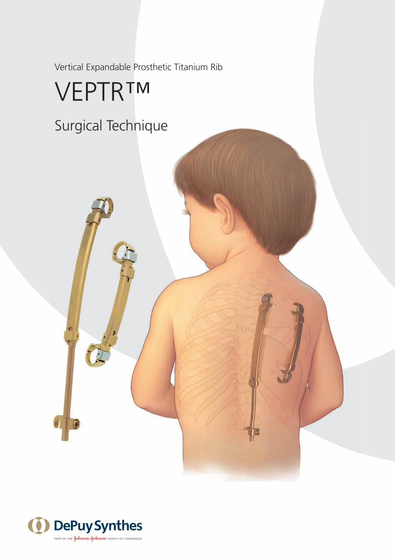
Vertical Expandable Prosthetic Titanium Rib
VEPTR™Surgical Technique

Image intensifier control
This description alone does not provide sufficient background for direct use of DePuy Synthes products. Instruction by a surgeon experienced in handling these products is highly recommended.
Processing, Reprocessing, Care and MaintenanceFor general guidelines, function control and dismantling of multi-part instruments, as well as processing guidelines for implants, please contact your local sales representative or refer to:http://emea.depuysynthes.com/hcp/reprocessing-care-maintenanceFor general information about reprocessing, care and maintenance of Synthes reusable devices, instrument trays and cases, as well as processing of Synthes non-sterile implants, please consult the Important Information leaflet (SE_023827) or refer to: http://emea.depuysynthes.com/hcp/reprocessing-care-maintenance
VEPTR Surgical Technique DePuy Synthes 1
Introduction VEPTR™ 2
Indications and Contraindications 3
Warnings and Precautions 4
Construct Options 5
AO Spine Principles 8
Surgical Technique Primary Procedure 9
Special Procedures 28
Expansion Procedure 29
Replacement of Components 32
Product Information Implants 33
Instruments 38
VEPTR System Instrument and Implant Set 44
Bibliography 48
Table of Contents
2 DePuy Synthes VEPTR Surgical Technique
VEPTR™
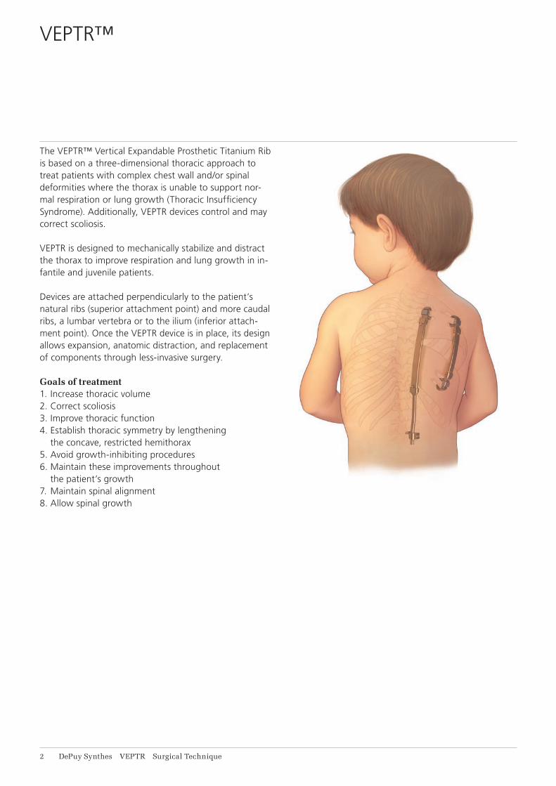
The VEPTR™ Vertical Expandable Prosthetic Titanium Rib is based on a three-dimensional thoracic ap proach to treat patients with complex chest wall and/or spinal deformities where the thorax is unable to support nor-mal respiration or lung growth (Thoracic Insufficiency Syndrome). Additionally, VEPTR devices control and may correct scoliosis.
VEPTR is designed to mechanically stabilize and distract the thorax to improve respiration and lung growth in in-fantile and juvenile patients.
Devices are attached perpendicularly to the patient’s natural ribs (superior attachment point) and more caudal ribs, a lumbar vertebra or to the ilium (inferior attach-ment point). Once the VEPTR device is in place, its design allows expansion, anatomic distraction, and replacement of components through less-invasive surgery.
Goals of treatment1. Increase thoracic volume 2. Correct scoliosis 3. Improve thoracic function 4. Establish thoracic symmetry by lengthening
the concave, restricted hemithorax 5. Avoid growth-inhibiting procedures 6. Maintain these improvements throughout
the patient’s growth7. Maintain spinal alignment8. Allow spinal growth
VEPTR Surgical Technique DePuy Synthes 3
Indications and Contraindications
IndicationsThe VEPTR device is indicated for:Primary Thoracic Insufficiency Syndrome (TIS) due to a three-dimensional deformity of the thorax• Progressive thoracic congenital scoliosis with concave
fused ribs• Progressive thoracic congenital scoliosis with flail chest
due to absent ribs• Progressive thoracic congenital, neurogenic
or idiopathic scoliosis without rib abnormality• Hypoplastic thorax syndrome, including
• Jeune’s syndrome,• Jarcho-Levin syndrome, • Cerebro costal mandibular syndrome,• others
• Congenital chest wall defect, posterolateral• Aquired chest wall defect, posterolateral• Chest wall tumor resection• Traumatic flail chest• Surgical separation of conjoined twinsSecondary Thoracic Insufficiency Syndrome due to lumbar kyphosis (non gibbus)
ContraindicationsThe VEPTR device should not be used under the follow-ing conditions:• Inadequate strength of bone (ribs/spine) for attach-
ment of the VEPTR device• Absence of proximal and distal ribs for attachment
of the VEPTR device• Absent diaphragmatic function• Inadequate soft tissue for coverage of the VEPTR
device• Age beyond skeletal maturity for uses of the VEPTR
device• Age below 6 months• Known allergy to any of the device materials• Infection at the operative site
4 DePuy Synthes VEPTR Surgical Technique
Patients implanted with the VEPTR device should not be braced. The VEPTR device is designed to allow for tho-racic cavity growth and the restrictive nature of a brace would not help the condition, but defeat its purpose.
Patients may require additional wound protection to prevent inadvertent rubbing or bumping of the wound. Patients with a diagnosis of spina bifida should have an occlusive dressing over the wound site to keep the site dry.
Warnings and Precautions

VEPTR Surgical Technique DePuy Synthes 5
Construct Options
Rib-to-Rib• Attaches to the superior rib and to the inferior rib• Components available in 70 mm or 220 mm radius
220 mm radius
70 mm radius

6 DePuy Synthes VEPTR Surgical Technique
Rib-to-Lumbar Lamina• Attaches to rib and to lumbar spine• Components available in 220 mm radius
Construct Options
VEPTR Surgical Technique DePuy Synthes 7
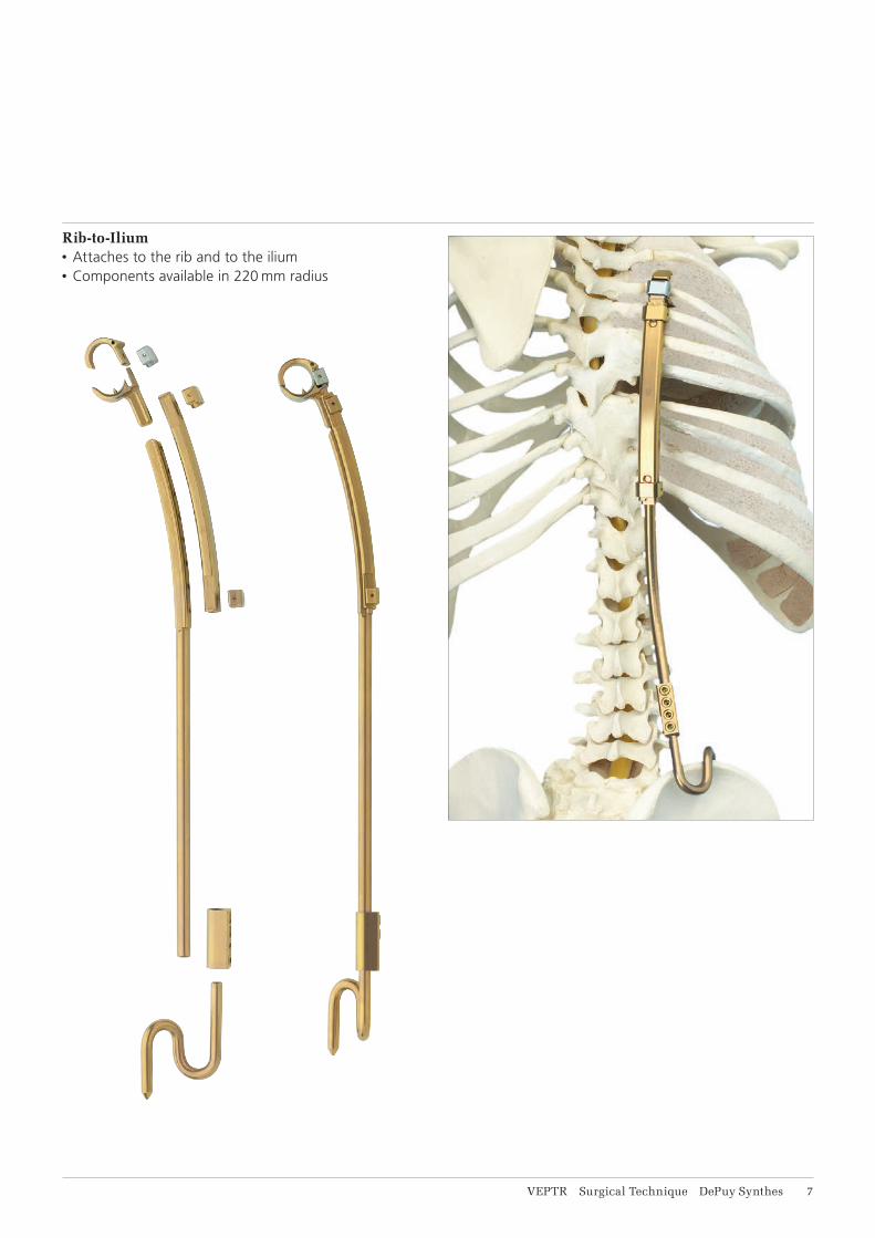
Rib-to-Ilium• Attaches to the rib and to the ilium• Components available in 220 mm radius

coronalaxial
sagittal
1 DePuy Synthes VEPTR Surgical Technique
The four principles to be considered as the foundation for proper spine patient management underpin the de-sign and delivery of the curriculum: stability, alignment, biology, and function.1,2
AO Spine Principles
StabilityStabilization to achieve a specifi c therapeutic outcome
BiologyEtiology, pathogenesis, neural protection, and tissue healing
Alignment Balancing the spine in 3 dimensions
FunctionPreservation and restoration of function to prevent disability
Copyright © 2012 by AOSpine
1 Aebi et al (1998)2 Aebi et al (2007)
VEPTR Surgical Technique DePuy Synthes 9
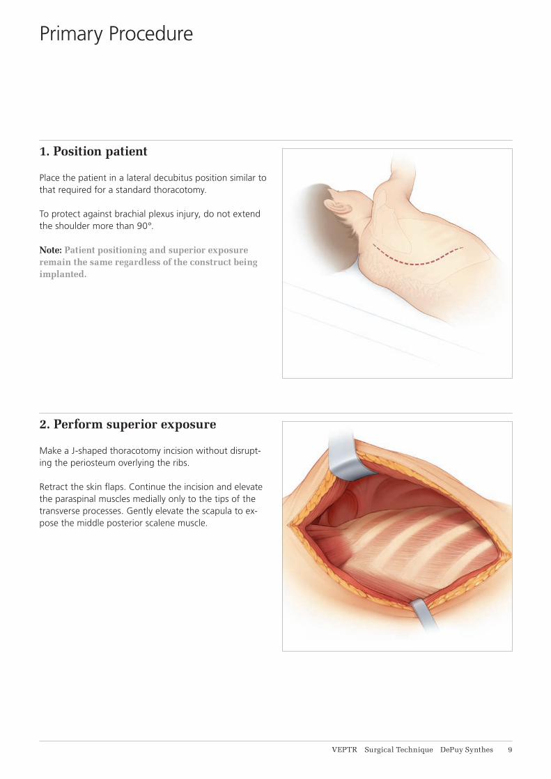
1. Position patient
Place the patient in a lateral decubitus position similar to that required for a standard thoracotomy.
To protect against brachial plexus injury, do not extend the shoulder more than 90°.
Note: Patient positioning and superior exposure remain the same regardless of the construct being implanted.
2. Perform superior exposure
Make a J-shaped thoracotomy incision without disrupt-ing the periosteum overlying the ribs.
Retract the skin flaps. Continue the incision and elevate the paraspinal muscles medially only to the tips of the transverse processes. Gently elevate the scapula to ex-pose the middle posterior scalene muscle.
Primary Procedure

11 DePuy Synthes VEPTR Surgical Technique
3a. Identify superior rib
Identify the superior rib to be used as the superior point of attachment. Mark this point and confirm location using radiographic imaging.
Note: Because of the risk of brachial plexus impinge-ment, do not choose the first rib as the superior point of attachment.
3b. Prepare rib for implants
Instruments
388.467 Rib Support Feeler
398.408 Periosteal Elevator, slightly curved blade, round tip, width 5 mm
U44-48320 Periosteal Elevator, curved, 20 cm
Make a 1-cm incision into the intercostal muscles above and below the rib where the superior cradle will attach. Insert a periosteal elevator to carefully elevate the peri-osteum adjacent to the lung.
Take care to preserve the soft tissue surrounding the rib to protect rib vascularity and the neurovascular bundle.
Use the rib support feeler to prepare the rib for the Cranial Rib Support and the Closing Half-Ring.
Cranial
Primary Procedure
VEPTR Surgical Technique DePuy Synthes 11
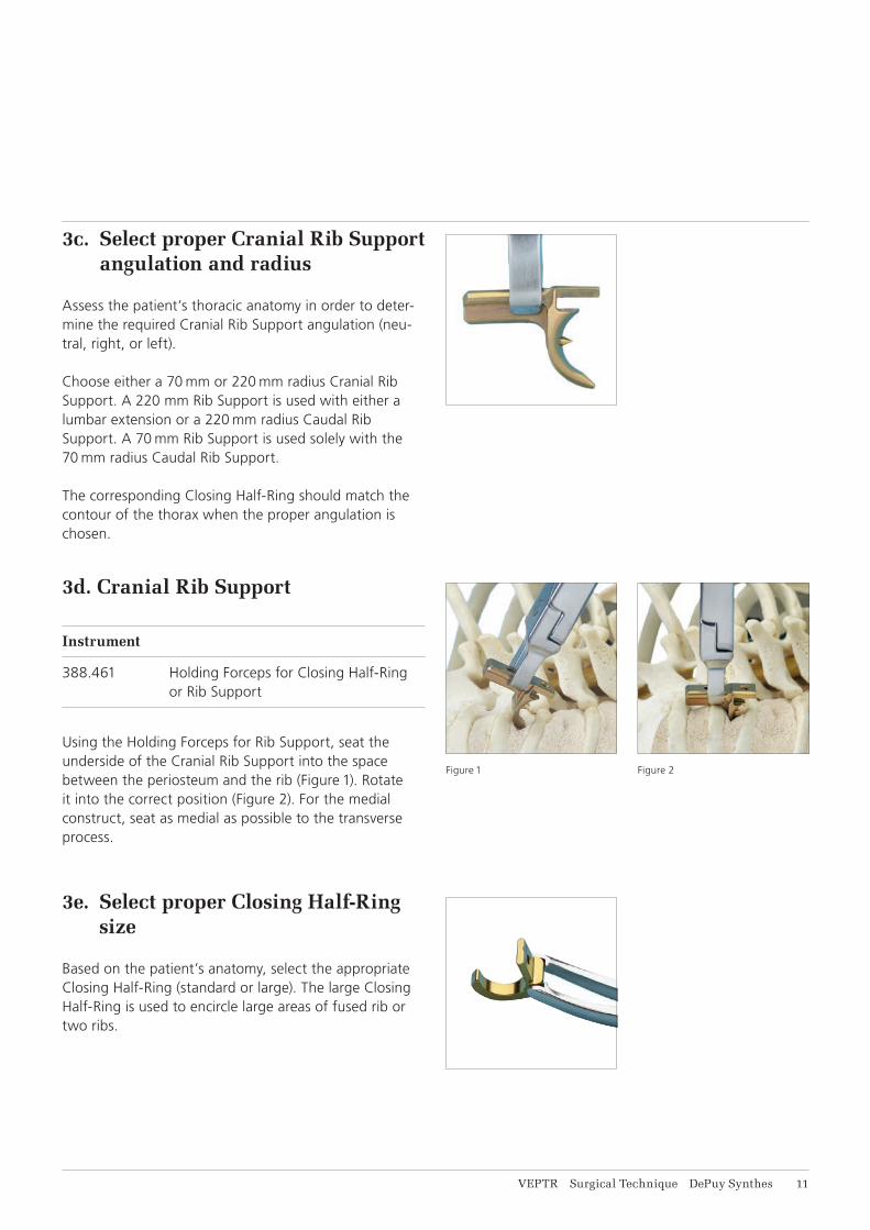
3c. Select proper Cranial Rib Support angulation and radius
Assess the patient’s thoracic anatomy in order to deter-mine the required Cranial Rib Support angulation (neu-tral, right, or left).
Choose either a 70 mm or 220 mm radius Cranial Rib Support. A 220 mm Rib Support is used with either a lumbar extension or a 220 mm radius Caudal Rib Support. A 70 mm Rib Support is used solely with the 70 mm radius Caudal Rib Support.
The corresponding Closing Half-Ring should match the contour of the thorax when the proper angulation is chosen.
3d. Cranial Rib Support
Instrument
388.461 Holding Forceps for Closing Half-Ring or Rib Support
Using the Holding Forceps for Rib Support, seat the underside of the Cranial Rib Support into the space between the periosteum and the rib (Figure 1). Rotate it into the correct position (Figure 2). For the medial construct, seat as medial as possible to the transverse process.
3e. Select proper Closing Half-Ring size
Based on the patient’s anatomy, select the appropriate Closing Half-Ring (standard or large). The large Closing Half-Ring is used to encircle large areas of fused rib or two ribs.
Figure 1 Figure 2

12 DePuy Synthes VEPTR Surgical Technique
3f. Insert Closing Half-Ring
Instrument
388.453 or Holding Forceps for Closing Half-Ring, 388.465 for VEPTR
Using the Holding Forceps for Closing Half-Ring, insert the Closing Half-Ring into the intercostal space above the contralateral side of the rib, with the open end fac-ing laterally to protect the great vessels (Figure 1). Rotate it distally to mate with the Cranial Rib Support (Figure 2).
3g. Align Cranial Rib Support and Closing Half-Ring
Instruments
388.488 Clip for Rib Support, for No. 388.494
388.489 Clip for Closing Half-Ring, for No. 388.494
388.494 Pliers for Closing Half-Ring and Rib Support
If the Closing Half-Ring and Cranial Rib Support are not aligned, prepare the Pliers for Closing Half-Ring and Rib Support. Affix the Clip for Closing Half-Ring and the Clip for Rib Support to the Pliers for Closing Half-Ring and Rib Support. This assembly is referred to as the Pliers for Closing Half-Ring and Rib Support.
Align the Cranial Rib Support with the Closing Half-Ring using the Pliers for Closing Half-Ring and Rib Support (Figure 3).
Figure 1 Figure 2
388.488
388.494388.489
Figure 3
Primary Procedure

VEPTR Surgical Technique DePuy Synthes 13
3h. Insert Lock for Rib Support
Instruments
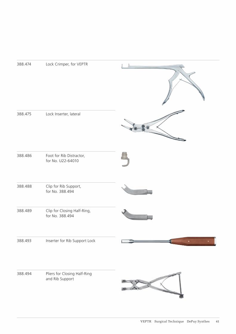
388.474 Lock Crimper, for VEPTR
388.475 Lock Inserter, lateral
388.493 Inserter for Rib Support Lock
Load a blue lock into the Inserter for Rib Support Lock (Figure 1). Insert the lock into the aligned holes of the Cranial Rib Support and the Closing Half-Ring (Figure 2). Using a hammer, firmly tap the Inserter to seat the lock.
The lateral Lock Inserter should always be used to ensure the lock is fully seated (Figure 3).
Alternatively, the lateral Lock Inserter can be used to seat the lock.
The implants now encircle the rib (Figure 4).
Figure 1
Figure 2
Figure 3 Figure 4
14 DePuy Synthes VEPTR Surgical Technique
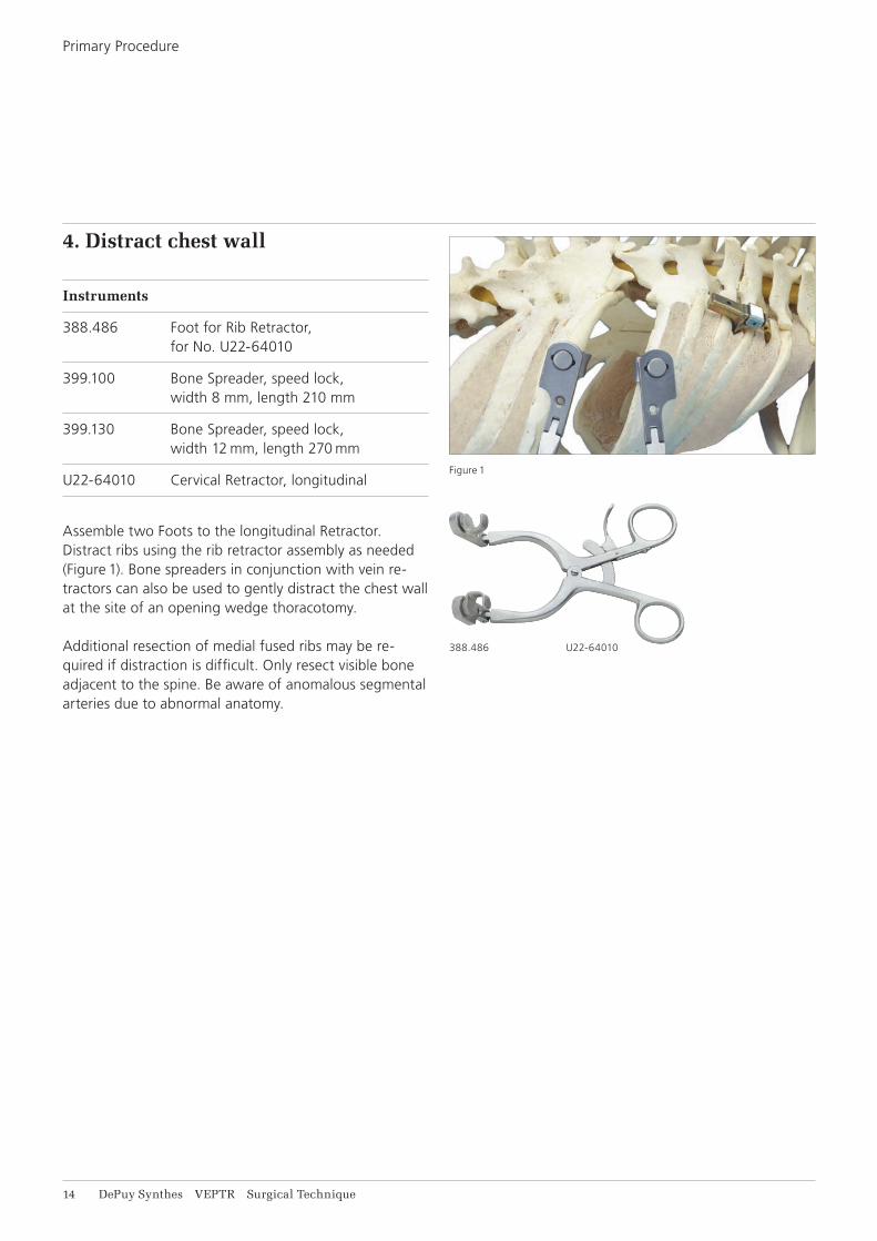
4. Distract chest wall
Instruments
388.486 Foot for Rib Retractor, for No. U22-64010
399.100 Bone Spreader, speed lock, width 8 mm, length 210 mm
399.130 Bone Spreader, speed lock, width 12 mm, length 270 mm
U22-64010 Cervical Retractor, longitudinal
Assemble two Foots to the longitudinal Retractor. Distract ribs using the rib retractor assembly as needed (Figure 1). Bone spreaders in conjunction with vein re-tractors can also be used to gently distract the chest wall at the site of an opening wedge thoracotomy.
Additional resection of medial fused ribs may be re-quired if distraction is difficult. Only resect visible bone adjacent to the spine. Be aware of anomalous segmental arteries due to abnormal anatomy.
Figure 1
U22-64010388.486
Primary Procedure

VEPTR Surgical Technique DePuy Synthes 15
5. Select appropriate Extension Bar
Instrument
388.870 Trial Rod B 6.0 mm, length 150 mm
Using the Trial Rod, measure the distance between the cranial rib and either the thoracolumbar junction or the chosen caudal rib to determine the appropriate Exten-sion Bar size.• Measure to the thoracolumbar junction when planning
a rib-to-ilium or rib-to-lumbar lamina construct. • Measure to the caudal rib when using a rib-to-rib con-
struct.
The measurement in centimeters will correspond to the correct Extension Bar size. For example, if the distance is determined to be 7 cm, use an Extension Bar marked with a 7. Implant sizes are identified from 4 to 13 in 1-cm increments.
16 DePuy Synthes VEPTR Surgical Technique
6. Lumbar extension assembly (Use for rib-to-lumbar lamina, rib-to-lumbar or rib-to-ilium constructs)
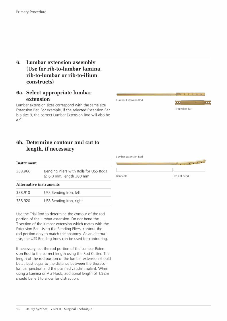
6a. Select appropriate lumbar extension
Lumbar extension sizes correspond with the same size Extension Bar. For example, if the selected Extension Bar is a size 9, the correct Lumbar Extension Rod will also be a 9.
6b. Determine contour and cut to length, if necessary
Instrument
388.960 Bending Pliers with Rolls for USS Rods B 6.0 mm, length 300 mm
Alternative instruments
388.910 USS Bending Iron, left
388.920 USS Bending Iron, right
Use the Trial Rod to determine the contour of the rod portion of the lumbar extension. Do not bend the T-section of the lumbar extension which mates with the Extension Bar. Using the Bending Pliers, contour the rod portion only to match the anatomy. As an alterna-tive, the USS Bending Irons can be used for contouring.
If necessary, cut the rod portion of the Lumbar Exten-sion Rod to the correct length using the Rod Cutter. The length of the rod portion of the lumbar extension should be at least equal to the distance between the thoraco-lumbar junction and the planned caudal implant. When using a Lamina or Ala Hook, additional length of 1.5 cm should be left to allow for distraction.
Do not bendBendable
Lumbar Extension Rod
Lumbar Extension Rod
Extension Bar
Primary Procedure

VEPTR Surgical Technique DePuy Synthes 17
6c. Insert Caudal Closure for Extension Bar
Instruments
388.456 or Lock Crimper, for VEPTR388.474
388.493 Inserter for Rib Support Lock
Prior to insertion, connect the Extension Bar with the lumbar extension by sliding the Lumbar Extension Rod into the Extension Bar. Align the most caudal hole in the Extension Bar with the most caudal hole in the Lumbar Extension Rod. The implants should overlap completely to maximize future expansion capacity.
Place a golden Closure for Extension Bar in this position using the Inserter for Rib Support Lock. With a hammer, firmly tap the Inserter to seat the lock. The Lock Crimper should always be used to ensure the Closure is fully seated.

11 DePuy Synthes VEPTR Surgical Technique
6d. Insert caudal implant
1. Lamina Hook (Use for rib-to-lumbar lamina construct)
Instrument
388.495 Holding Forceps for Hooks, for VEPTR
Make a 4-cm, longitudinal, paraspinal skin incision on the concave side of the curve at the lumbar interspace that was selected preoperatively (Figure 1). Retract the paraspinal muscles unilaterally. Do not disturb the facet joints.
Use a Lamina Feeler to separate the ligamentum flavum unilaterally from the underside of the lamina to ensure good bony contact with the Lamina Hook, leaving the interspinous ligament intact. Resect enough ligamentum flavum for the hook to pass.
Choose the appropriate Lamina Hook (right or left). The hook will be placed downward-facing and the setscrew will be lateral.
Use the Holding Forceps to place the hook in the desired location on the lumbar vertebra (Figure 2).
Tip: The hook can be further secured by using a heavy, nonabsorbable suture around the spinous process.
388.495
Figure 1
Figure 2
Primary Procedure
VEPTR Surgical Technique DePuy Synthes 19
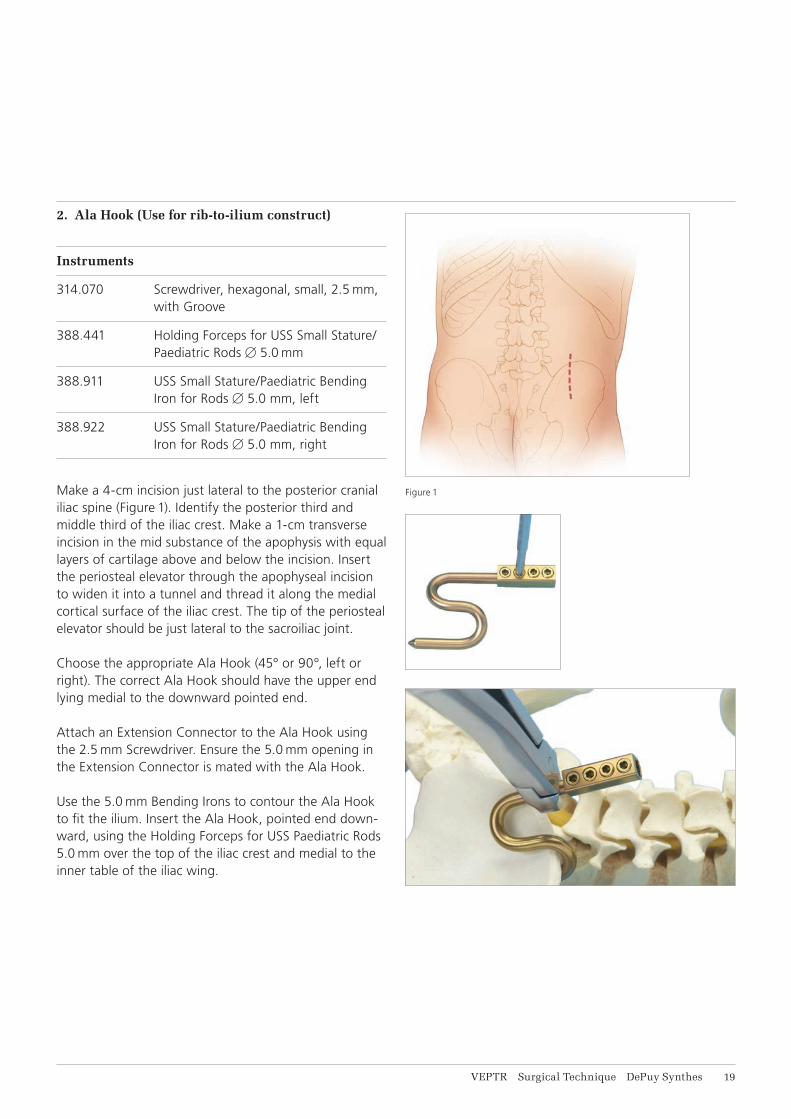
2. Ala Hook (Use for rib-to-ilium construct)
Instruments
314.070 Screwdriver, hexagonal, small, 2.5 mm, with Groove
388.441 Holding Forceps for USS Small Stature/Paediatric Rods B 5.0 mm
388.911 USS Small Stature/Paediatric Bending Iron for Rods B 5.0 mm, left
388.922 USS Small Stature/Paediatric Bending Iron for Rods B 5.0 mm, right
Make a 4-cm incision just lateral to the posterior cranial iliac spine (Figure 1). Identify the posterior third and middle third of the iliac crest. Make a 1-cm transverse incision in the mid substance of the apophysis with equal layers of cartilage above and below the incision. Insert the periosteal elevator through the apophyseal incision to widen it into a tunnel and thread it along the medial cortical surface of the iliac crest. The tip of the periosteal elevator should be just lateral to the sacroiliac joint.
Choose the appropriate Ala Hook (45° or 90°, left or right). The correct Ala Hook should have the upper end lying medial to the downward pointed end.
Attach an Extension Connector to the Ala Hook using the 2.5 mm Screwdriver. Ensure the 5.0 mm opening in the Extension Connector is mated with the Ala Hook.
Use the 5.0 mm Bending Irons to contour the Ala Hook to fit the ilium. Insert the Ala Hook, pointed end down-ward, using the Holding Forceps for USS Paediatric Rods 5.0 mm over the top of the iliac crest and medial to the inner table of the iliac wing.
Figure 1
21 DePuy Synthes VEPTR Surgical Technique
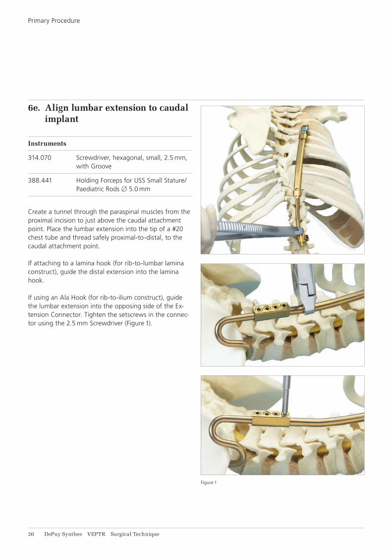
6e. Align lumbar extension to caudal implant
Instruments
314.070 Screwdriver, hexagonal, small, 2.5 mm, with Groove
388.441 Holding Forceps for USS Small Stature/Paediatric Rods B 5.0 mm
Create a tunnel through the paraspinal muscles from the proximal incision to just above the caudal attachment point. Place the lumbar extension into the tip of a #20 chest tube and thread safely proximal-to-distal, to the caudal attachment point.
If attaching to a lamina hook (for rib-to-lumbar lamina construct), guide the distal extension into the lamina hook.
If using an Ala Hook (for rib-to-ilium construct), guide the lumbar extension into the opposing side of the Ex-tension Connector. Tighten the setscrews in the connec-tor using the 2.5 mm Screwdriver (Figure 1).
Figure 1
Primary Procedure
VEPTR Surgical Technique DePuy Synthes 21
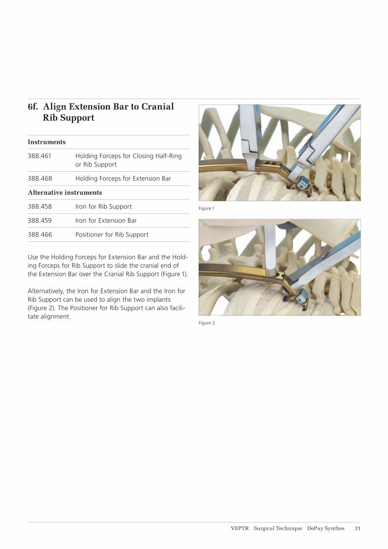
6f. Align Extension Bar to Cranial Rib Support
Instruments
388.461 Holding Forceps for Closing Half-Ring or Rib Support
388.468 Holding Forceps for Extension Bar
Alternative instruments
388.458 Iron for Rib Support
388.459 Iron for Extension Bar
388.466 Positioner for Rib Support
Use the Holding Forceps for Extension Bar and the Hold-ing Forceps for Rib Support to slide the cranial end of the Extension Bar over the Cranial Rib Support (Figure 1).
Alternatively, the Iron for Extension Bar and the Iron for Rib Support can be used to align the two implants (Figure 2). The Positioner for Rib Support can also facili-tate alignment.
Figure 2
Figure 1

22 DePuy Synthes VEPTR Surgical Technique
Figure 1
6g. Insert Closure for Extension Bar
Instruments
388.464 Spreader for Rib Support
388.474 Lock Crimper, for VEPTR
388.475 Lock Inserter, lateral
388.493 Inserter for Rib Support Lock
Insert a golden Closure for Extension Bar using the In-serter for Rib Support Lock (Figure 1) to fix the Extension Bar to the Cranial Rib Support.
Note: If necessary, the Spreader for Rib Support can be used to align the holes.
Using a hammer, firmly tap the Inserter to seat the lock.
The Lock Crimper should always be used to ensure the lock is fully seated.
Alternatively, the lateral Lock Inserter can be used to seat the lock.
Primary Procedure
VEPTR Surgical Technique DePuy Synthes 23
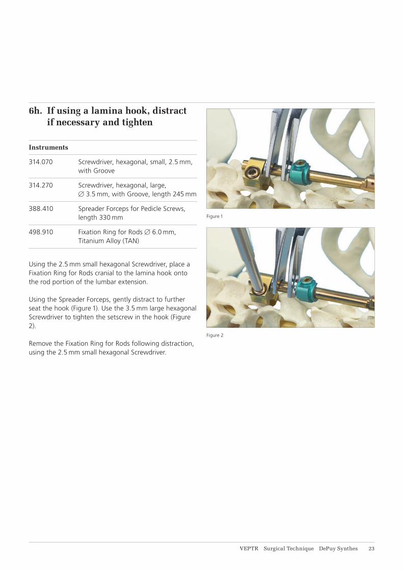
6h. If using a lamina hook, distract if necessary and tighten
Instruments
314.070 Screwdriver, hexagonal, small, 2.5 mm, with Groove
314.270 Screwdriver, hexagonal, large, B 3.5 mm, with Groove, length 245 mm
388.410 Spreader Forceps for Pedicle Screws, length 330 mm
498.910 Fixation Ring for Rods B 6.0 mm, Titanium Alloy (TAN)
Using the 2.5 mm small hexagonal Screwdriver, place a Fixation Ring for Rods cranial to the lamina hook onto the rod portion of the lumbar extension.
Using the Spreader Forceps, gently distract to further seat the hook (Figure 1). Use the 3.5 mm large hexagonal Screwdriver to tighten the setscrew in the hook (Figure 2).
Remove the Fixation Ring for Rods following distraction, using the 2.5 mm small hexagonal Screwdriver.
Figure 1
Figure 2
24 DePuy Synthes VEPTR Surgical Technique
7. Caudal Rib Support (Use for rib-to-rib constructs)
7a. Choose appropriate caudal rib
The proper caudal rib for attachment of the rib-to-rib device should be transverse in orientation and of ade-quate width. Do not choose an oblique rib, such as rib 11 or 12.
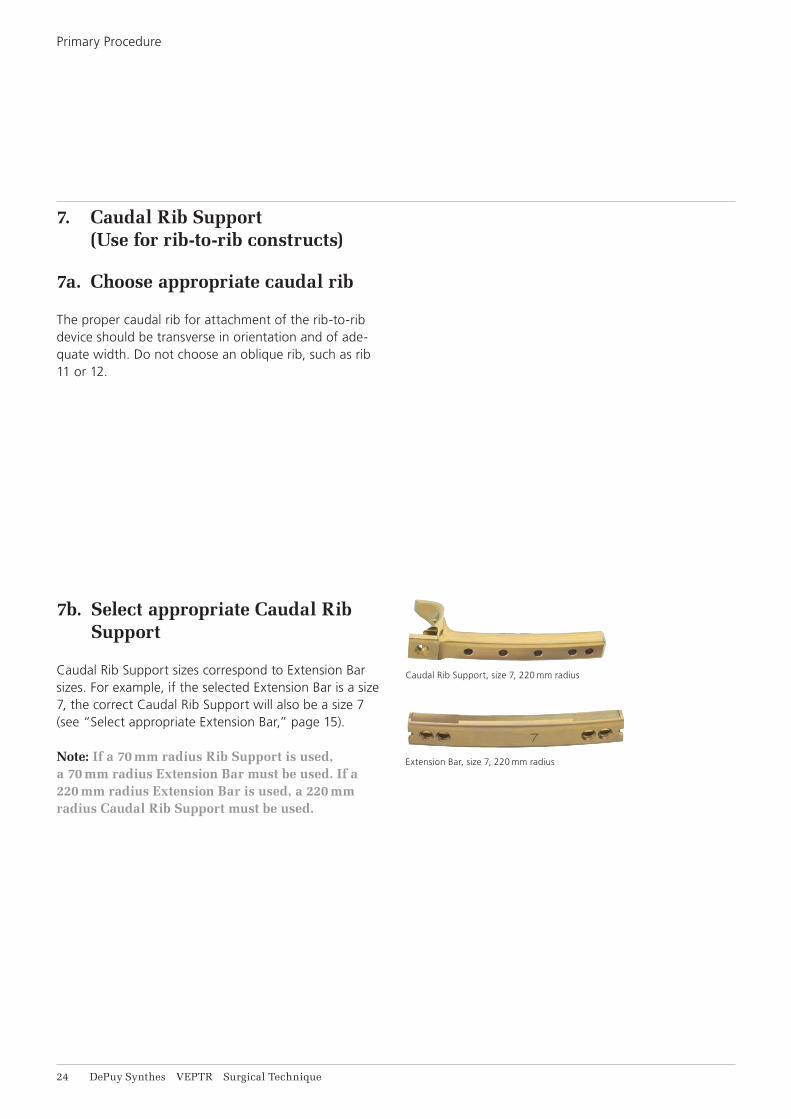
7b. Select appropriate Caudal Rib Support
Caudal Rib Support sizes correspond to Extension Bar sizes. For example, if the selected Extension Bar is a size 7, the correct Caudal Rib Support will also be a size 7 (see “Select appropriate Extension Bar,” page 15).
Note: If a 70 mm radius Rib Support is used, a 70 mm radius Extension Bar must be used. If a 220 mm radius Extension Bar is used, a 220 mm radius Caudal Rib Support must be used.
Caudal Rib Support, size 7, 220 mm radius
Extension Bar, size 7, 220 mm radius
Primary Procedure
VEPTR Surgical Technique DePuy Synthes 25
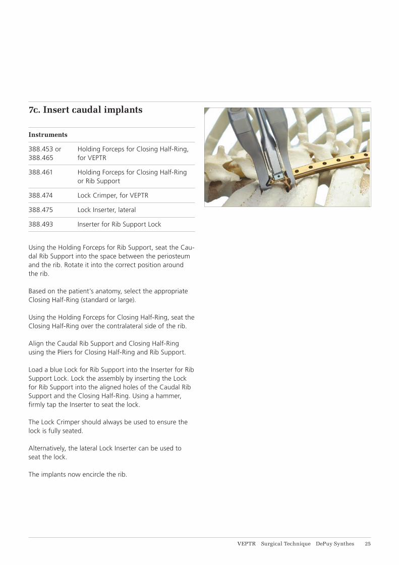
7c. Insert caudal implants
Instruments
388.453 or Holding Forceps for Closing Half-Ring, 388.465 for VEPTR
388.461 Holding Forceps for Closing Half-Ring or Rib Support
388.474 Lock Crimper, for VEPTR
388.475 Lock Inserter, lateral
388.493 Inserter for Rib Support Lock
Using the Holding Forceps for Rib Support, seat the Cau-dal Rib Support into the space between the periosteum and the rib. Rotate it into the correct position around the rib.
Based on the patient’s anatomy, select the appropriate Closing Half-Ring (standard or large).
Using the Holding Forceps for Closing Half-Ring, seat the Closing Half-Ring over the contralateral side of the rib.
Align the Caudal Rib Support and Closing Half-Ring using the Pliers for Closing Half-Ring and Rib Support.
Load a blue Lock for Rib Support into the Inserter for Rib Support Lock. Lock the assembly by inserting the Lock for Rib Support into the aligned holes of the Caudal Rib Support and the Closing Half-Ring. Using a hammer, firmly tap the Inserter to seat the lock.
The Lock Crimper should always be used to ensure the lock is fully seated.
Alternatively, the lateral Lock Inserter can be used to seat the lock.
The implants now encircle the rib.
26 DePuy Synthes VEPTR Surgical Technique
7d. Assemble construct
Instruments
388.458 Iron for Rib Support
388.459 Iron for Extension Bar
388.464 Spreader for Rib Support
388.466 Positioner for Rib Support
388.468 Holding Forceps for Extension Bar
388.472 Distractor, curved, for Extension Bar
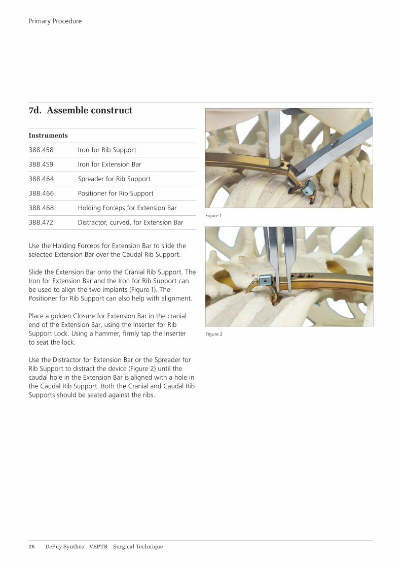
Use the Holding Forceps for Extension Bar to slide the selected Extension Bar over the Caudal Rib Support.
Slide the Extension Bar onto the Cranial Rib Support. The Iron for Extension Bar and the Iron for Rib Support can be used to align the two implants (Figure 1). The Positioner for Rib Support can also help with alignment.
Place a golden Closure for Extension Bar in the cranial end of the Extension Bar, using the Inserter for Rib Support Lock. Using a hammer, firmly tap the Inserter to seat the lock.
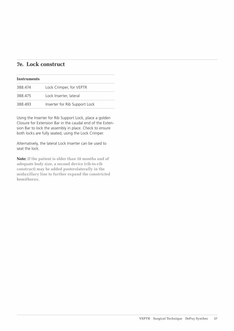
Use the Distractor for Extension Bar or the Spreader for Rib Support to distract the device (Figure 2) until the caudal hole in the Extension Bar is aligned with a hole in the Caudal Rib Support. Both the Cranial and Caudal Rib Supports should be seated against the ribs.
Figure 2
Figure 1
Primary Procedure
VEPTR Surgical Technique DePuy Synthes 27
7e. Lock construct
Instruments
388.474 Lock Crimper, for VEPTR
388.475 Lock Inserter, lateral
388.493 Inserter for Rib Support Lock
Using the Inserter for Rib Support Lock, place a golden Closure for Extension Bar in the caudal end of the Exten-sion Bar to lock the assembly in place. Check to ensure both locks are fully seated, using the Lock Crimper.
Alternatively, the lateral Lock Inserter can be used to seat the lock.
Note: If the patient is older than 18 months and of adequate body size, a second device (rib-to-rib construct) may be added posterolaterally in the midaxillary line to further expand the constricted hemithorax.

21 DePuy Synthes VEPTR Surgical Technique
Fused ribs and scoliosis
After the Cranial Rib Support and caudal point of attach-ment have been chosen, perform an opening wedge thoracostomy through the fused ribs at the apex of the thoracic deformity from the tip of the transverse process to the costochondral junction, in the general orientation of the ribs.
Separate the fusion mass. Ensure the continuity between the anterior and posterior attachments of the newly sep-arated ribs.
Continue the procedure using the appropriate construct technique.
For a detailed description of a thoracostomy, see Robert M. Campbell Jr., MD; Melvin D. Smith, MD; Anna K. Hell-Vocke, MD. “Expansion Thoracoplasty: The Surgical Technique of Opening-Wedge Thoracostomy.” Journal of Bone and Joint Surgery–American Volume. 86-A Supple-ment 1:51–64, 2004.
Hypoplastic thorax
Instrument
391.820 Wire Bending Pliers, length 155 mm, for Wires up to B 1.25 mm
A hypoplastic, low-volume thorax (as seen with Jeune’s syndrome) requires the use of a 70 mm radius rib-to-rib construct (70 mm radius implants include: Cranial Rib Support, Caudal Rib Support, Extension Bar). These con-structs are placed bilaterally in separate procedures.
After inserting both the Cranial and Caudal Rib Sup-ports, free the central segment of the selected hemi-thorax by making transverse incisions in the periosteum to enable anterior and posterior osteotomies.
Perform anterior and posterior osteotomies from ribs 3 through 8. Distract the mobilized chest segment pos-terolaterally.
Place retractors subperiosteally to protect the underlying lung.
Choose two to three sites in the central portion of the mobilized segment to insert the 2.0 mm titanium rod, which will hold the ribs to the construct. Bend the rod to form a gentle curve, using the Wire Bending Pliers.
Assemble the construct as stated in the rib-to-rib con-struct section.
After the construct has been completely assembled and locked, use the Wire Bending Pliers to again grasp the rods and contour around the implanted rib-to-rib con-struct, leaving space available to remove the locks and expand the construct.
Special Procedures
2.0 mm Rod
VEPTR Surgical Technique DePuy Synthes 29
Expansion Procedure
Note: When performing an expansion procedure on patients implanted with a VEPTR device, the deci-sion to distract the implanted VEPTR device should consider the risk/benefit of lengthening the device further versus alternative options including replace-ment of cranial and/or caudal construct components to longer ones. Remaining vigilant and closely moni-toring patients for any device breakage with careful interpretation of this area on post-op imaging is rec-ommended.
1. Position patient
Place the patient in a lateral decubitus or prone position.
2. Exposure
Identify the approximate location of the caudal Closure for Extension Bar through palpation and/or radiographic marker. Make a transverse or longitudinal incision over the caudal Closure for Extension Bar.

31 DePuy Synthes VEPTR Surgical Technique
3. Remove lock
Instruments
388.452 Lock Removal Pliers, for VEPTR
388.462 Lock Removal Device, for VEPTR
Remove the golden Closure for Extension Bar using the Lock Removal Pliers or the Lock Removal Device.
4. Distraction
Instruments
388.457 Distraction Pin for VEPTR, for temporary use
388.471 Rib Distraction Pliers
388.472 Distractor, curved, for Extension Bar
498.910 Fixation Ring for Rods B 6.0 mm, Titanium Alloy (TAN)
Use the Rib Distraction Pliers or the Distractor for Exten-sion Bar in conjunction with a Fixation Ring for Rods to gently distract the implanted device until the device is adequately lengthened. Use the Temporary Distraction Pins as placeholders to assist distraction.
Expansion procedure

VEPTR Surgical Technique DePuy Synthes 31
5. Final locking
Instruments
388.474 Lock Crimper, for VEPTR
388.475 Lock Inserter, lateral
388.493 Inserter for Rib Support Lock
Insert a new golden Closure for Extension Bar using the Inserter for Rib Support Lock to fix the Extension Bar in its distracted position. With a hammer, tap the Inserter to seat the Closure. Check to ensure the closure is fully seated using the Lock Crimper.
Alternatively, the lateral Lock Inserter can be used to seat the lock.
32 DePuy Synthes VEPTR Surgical Technique
Replacement of components
Instrument
388.452 Lock Removal Pliers, for VEPTR
For replacement of the Extension Bar, Caudal Rib Sup-port or Lumbar Extension Rod, make three transverse incisions, one at the midportion of the implanted con-struct and others along the distal and proximal portions. A portion of the previous thoracostomy incision may be used.
Unlock the device by removing the golden Closure(s) for Extension Bars using the Lock Removal Pliers. Remove the required components and insert the new components through the fibrous canal surrounding the old devices.
Install new Closure(s) for Extension Bars.
Refer to detailed instructions within this surgical tech-nique to install specific components.
Replacement of Components
VEPTR Surgical Technique DePuy Synthes 33
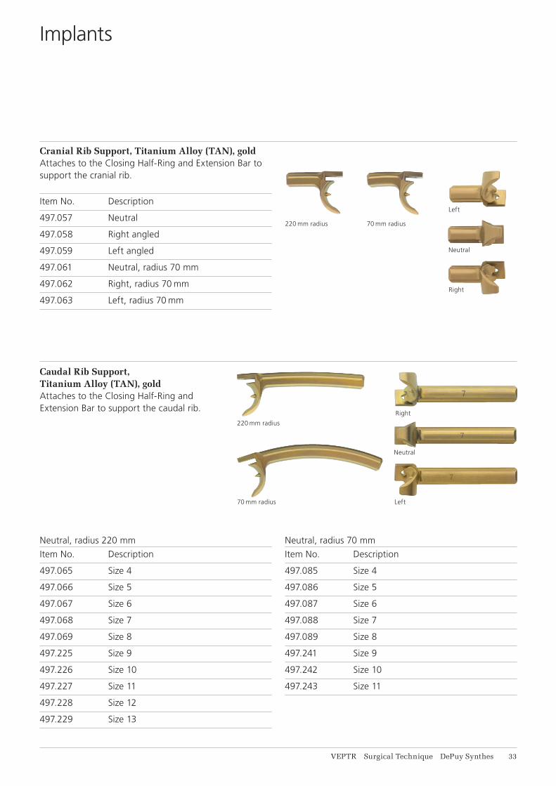
Cranial Rib Support, Titanium Alloy (TAN), goldAttaches to the Closing Half-Ring and Extension Bar to support the cranial rib.
Item No. Description
497.057 Neutral
497.058 Right angled
497.059 Left angled
497.061 Neutral, radius 70 mm
497.062 Right, radius 70 mm
497.063 Left, radius 70 mm
Neutral, radius 220 mm
Item No. Description
497.065 Size 4
497.066 Size 5
497.067 Size 6
497.068 Size 7
497.069 Size 8
497.225 Size 9
497.226 Size 10
497.227 Size 11
497.228 Size 12
497.229 Size 13
Neutral, radius 70 mm
Item No. Description
497.085 Size 4
497.086 Size 5
497.087 Size 6
497.088 Size 7
497.089 Size 8
497.241 Size 9
497.242 Size 10
497.243 Size 11
Implants
Left
Right
Neutral
220 mm radius 70 mm radius
220 mm radius
Left
Neutral
70 mm radius
Right
Caudal Rib Support, Titanium Alloy (TAN), goldAttaches to the Closing Half-Ring and Extension Bar to support the caudal rib.

34 DePuy Synthes VEPTR Surgical Technique
Right angled, radius 220 mm
Item No. Description
497.071 Size 4
497.072 Size 5
497.073 Size 6
497.074 Size 7
497.075 Size 8
497.230 Size 9
497.231 Size 10
497.232 Size 11
497.233 Size 12
497.234 Size 13
Left angled, radius 220 mm
Item No. Description
497.076 Size 4
497.077 Size 5
497.078 Size 6
497.079 Size 7
497.080 Size 8
497.235 Size 9
497.236 Size 10
497.237 Size 11
497.238 Size 12
497.239 Size 13
Right angled, radius 70 mm
Item No. Description
497.091 Size 4
497.092 Size 5
497.093 Size 6
497.094 Size 7
497.095 Size 8
497.244 Size 9
497.245 Size 10
497.246 Size 11
Left angled, radius 70 mm
Item No. Description
497.096 Size 4
497.097 Size 5
497.098 Size 6
497.099 Size 7
497.100 Size 8
497.247 Size 9
497.248 Size 10
497.249 Size 11
Implants

VEPTR Surgical Technique DePuy Synthes 35
Closing Half-Ring• Attaches to the Cranial or Caudal Rib Support
to encircle the cranial or caudal rib(s)• Two sizes, standard and extended
Item No. Description
497.126 Closing Half-Ring for Rib Support, Titanium Alloy (TAN), gold
497.129 Closing Half-Ring for Rib Support, large, Titanium Alloy (TAN)
Locks• Lock for Rib Support (blue) connects the Closing
Half-Ring to the Cranial Rib Support or the Caudal Rib Support
• Closure for Extension Bar (gold) connects the Extension Bar to the Cranial Rib Support, Caudal Rib Support or Lumbar Extension Rod
Item No. Description
497.128 Lock for Rib Support, Titanium Alloy (TAN), blue
497.125 Closure for Extension Bar, Titanium Alloy (TAN), gold
Standard Large
Lock for Rib Support (blue)
Closure for Extension Bar (gold)

36 DePuy Synthes VEPTR Surgical Technique
Extension Bar, radius 220 mm
Item No. Description
497.103 Size 4
497.104 Size 5
497.105 Size 6
497.106 Size 7
497.107 Size 8
497.108 Size 9
497.109 Size 10
497.110 Size 11
497.111 Size 12
497.112 Size 13
Lumbar Extension Rod, radius 220 mm, Titanium Alloy (TAN), goldAttaches the Extension Bar to the Lamina Hook or the Extension Connector.
Item No. Description
497.131 Size 6
497.132 Size 7
497.133 Size 8
497.134 Size 9
497.251 Size 10
497.252 Size 11
497.253 Size 12
497.254 Size 13
Extension Bar, radius 70 mm
Item No. Description
497.115 Size 4
497.116 Size 5
497.117 Size 6
497.118 Size 7
497.119 Size 8
497.120 Size 9
497.121 Size 10
497.122 Size 11
Extension Bar, Titanium Alloy (TAN), goldAttaches the Cranial Rib Support to the Caudal Rib Support or Lumbar Extension Rod.
radius 70 mmradius 220 mm
Extension Bar, radius 220 mm
Implants
VEPTR Surgical Technique DePuy Synthes 37
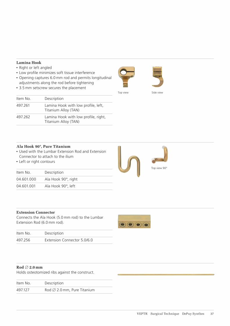
Lamina Hook• Right or left angled• Low profile minimizes soft tissue interference• Opening captures 6.0 mm rod and permits longitudinal
adjustments along the rod before tightening• 3.5 mm setscrew secures the placement
Item No. Description
497.261 Lamina Hook with low profile, left, Titanium Alloy (TAN)
497.262 Lamina Hook with low profile, right, Titanium Alloy (TAN)
Ala Hook 90°, Pure Titanium• Used with the Lumbar Extension Rod and Extension
Connector to attach to the ilium• Left or right contours
Item No. Description
04.601.000 Ala Hook 90°, right
04.601.001 Ala Hook 90°, left
Extension Connector Connects the Ala Hook (5.0 mm rod) to the Lumbar Extension Rod (6.0 mm rod).
Item No. Description
497.256 Extension Connector 5.0/6.0
Rod B 2.0 mm Holds osteotomized ribs against the construct.
Item No. Description
497.127 Rod B 2.0 mm, Pure Titanium
Top view 90°
Top view Side view

31 DePuy Synthes VEPTR Surgical Technique
Instruments
314.070 Screwdriver, hexagonal, small, 2.5 mm, with Groove
314.270 Screwdriver, hexagonal, large, B 3.5 mm, with Groove, length 245 mm
388.920 USS Bending Iron, right
388.910 USS Bending Iron, left
388.410 Spreader Forceps for Pedicle Screws, length 330 mm
388.441 Holding Forceps for USS Small Stature/Paediatric Rods B 5.0 mm
388.422 Compression Forceps, length 335 mm, for Pedicle Screws

VEPTR Surgical Technique DePuy Synthes 39
388.457 Distraction Pin for VEPTR, for temporary use
388.458 Iron for Rib Support
388.459 Iron for Extension Bar
388.461 Holding Forceps for Closing Half-Ring or Rib Support
388.462 Lock Removal Device, for VEPTR
388.464 Spreader for Rib Support
388.452 Lock Removal Pliers, for VEPTR

41 DePuy Synthes VEPTR Surgical Technique
388.465 Holding Forceps for Closing Half-Ring, for VEPTR
388.466 Positioner for Rib Support
388.467 Rib Support Feeler
388.468 Holding Forceps for Extension Bar
388.471 Rib Distraction Pliers
388.472 Distractor, curved, for Extension Bar
Instruments
VEPTR Surgical Technique DePuy Synthes 41
388.486 Foot for Rib Distractor, for No. U22-64010
388.488 Clip for Rib Support, for No. 388.494
388.489 Clip for Closing Half-Ring, for No. 388.494
388.493 Inserter for Rib Support Lock
388.494 Pliers for Closing Half-Ring and Rib Support
388.474 Lock Crimper, for VEPTR
388.475 Lock Inserter, lateral

42 DePuy Synthes VEPTR Surgical Technique
388.495 Holding Forceps for Hooks, for VEPTR
399.100 Bone Spreader, speed lock, width 8 mm, length 210 mm
388.870 Trial Rod B 6.0 mm, length 150 mm
388.911 USS Small Stature/Paediatric Bending Iron for Rods B 5.0 mm, left
388.922 USS Small Stature/Paediatric Bending Iron for Rods B 5.0 mm, right
388.940 Rod Pusher for USS Rods B 6.0 mm
388.960 Bending Pliers with Rolls for USS Rods B 6.0 mm, length 300 mm
Instruments
VEPTR Surgical Technique DePuy Synthes 43
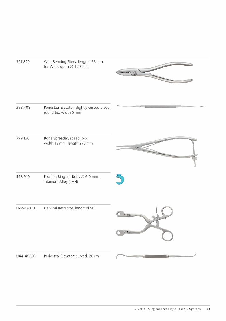
398.408 Periosteal Elevator, slightly curved blade, round tip, width 5 mm
399.130 Bone Spreader, speed lock, width 12 mm, length 270 mm
498.910 Fixation Ring for Rods B 6.0 mm, Titanium Alloy (TAN)
U22-64010 Cervical Retractor, longitudinal
U44-48320 Periosteal Elevator, curved, 20 cm
391.820 Wire Bending Pliers, length 155 mm, for Wires up to B 1.25 mm
44 DePuy Synthes VEPTR Surgical Technique
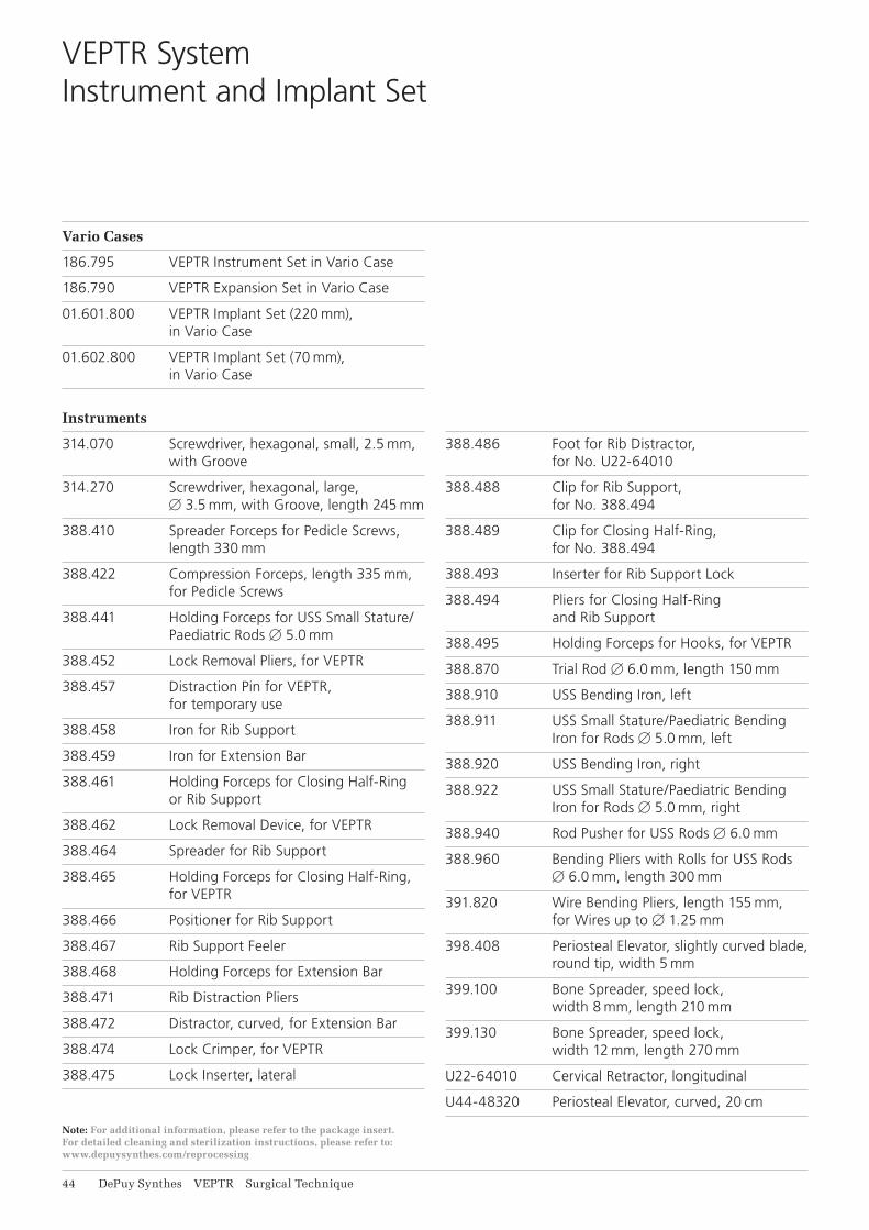
Vario Cases
186.795 VEPTR Instrument Set in Vario Case
186.790 VEPTR Expansion Set in Vario Case
01.601.800 VEPTR Implant Set (220 mm), in Vario Case
01.602.800 VEPTR Implant Set (70 mm), in Vario Case
Instruments
314.070 Screwdriver, hexagonal, small, 2.5 mm, with Groove
314.270 Screwdriver, hexagonal, large, B 3.5 mm, with Groove, length 245 mm
388.410 Spreader Forceps for Pedicle Screws, length 330 mm
388.422 Compression Forceps, length 335 mm, for Pedicle Screws
388.441 Holding Forceps for USS Small Stature/Paediatric Rods B 5.0 mm
388.452 Lock Removal Pliers, for VEPTR
388.457 Distraction Pin for VEPTR, for temporary use
388.458 Iron for Rib Support
388.459 Iron for Extension Bar
388.461 Holding Forceps for Closing Half-Ring or Rib Support
388.462 Lock Removal Device, for VEPTR
388.464 Spreader for Rib Support
388.465 Holding Forceps for Closing Half-Ring, for VEPTR
388.466 Positioner for Rib Support
388.467 Rib Support Feeler
388.468 Holding Forceps for Extension Bar
388.471 Rib Distraction Pliers
388.472 Distractor, curved, for Extension Bar
388.474 Lock Crimper, for VEPTR
388.475 Lock Inserter, lateral
388.486 Foot for Rib Distractor, for No. U22-64010
388.488 Clip for Rib Support, for No. 388.494
388.489 Clip for Closing Half-Ring, for No. 388.494
388.493 Inserter for Rib Support Lock
388.494 Pliers for Closing Half-Ring and Rib Support
388.495 Holding Forceps for Hooks, for VEPTR
388.870 Trial Rod B 6.0 mm, length 150 mm
388.910 USS Bending Iron, left
388.911 USS Small Stature/Paediatric Bending Iron for Rods B 5.0 mm, left
388.920 USS Bending Iron, right
388.922 USS Small Stature/Paediatric Bending Iron for Rods B 5.0 mm, right
388.940 Rod Pusher for USS Rods B 6.0 mm
388.960 Bending Pliers with Rolls for USS Rods B 6.0 mm, length 300 mm
391.820 Wire Bending Pliers, length 155 mm, for Wires up to B 1.25 mm
398.408 Periosteal Elevator, slightly curved blade, round tip, width 5 mm
399.100 Bone Spreader, speed lock, width 8 mm, length 210 mm
399.130 Bone Spreader, speed lock, width 12 mm, length 270 mm
U22-64010 Cervical Retractor, longitudinal
U44-48320 Periosteal Elevator, curved, 20 cm
Note: For additional information, please refer to the package insert. For detailed cleaning and sterilization instructions, please refer to: www.depuysynthes.com/reprocessing
VEPTR System Instrument and Implant Set
VEPTR Surgical Technique DePuy Synthes 45
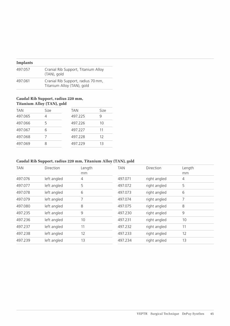
Implants
497.057 Cranial Rib Support, Titanium Alloy (TAN), gold
497.061 Cranial Rib Support, radius 70 mm, Titanium Alloy (TAN), gold
Caudal Rib Support, radius 220 mm, Titanium Alloy (TAN), gold
TAN Size TAN Size
497.065 4 497.225 9
497.066 5 497.226 10
497.067 6 497.227 11
497.068 7 497.228 12
497.069 8 497.229 13
Caudal Rib Support, radius 220 mm, Titanium Alloy (TAN), gold
TAN Direction Length mm
497.076 left angled 4
497.077 left angled 5
497.078 left angled 6
497.079 left angled 7
497.080 left angled 8
497.235 left angled 9
497.236 left angled 10
497.237 left angled 11
497.238 left angled 12
497.239 left angled 13
TAN Direction Length mm
497.071 right angled 4
497.072 right angled 5
497.073 right angled 6
497.074 right angled 7
497.075 right angled 8
497.230 right angled 9
497.231 right angled 10
497.232 right angled 11
497.233 right angled 12
497.234 right angled 13
46 DePuy Synthes VEPTR Surgical Technique
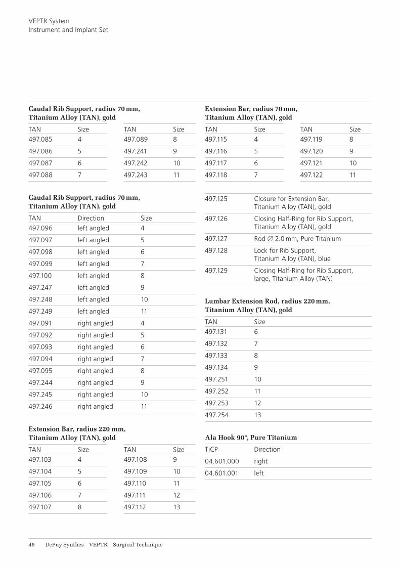
Caudal Rib Support, radius 70 mm, Titanium Alloy (TAN), gold
TAN Size TAN Size
497.085 4 497.089 8
497.086 5 497.241 9
497.087 6 497.242 10
497.088 7 497.243 11
Caudal Rib Support, radius 70 mm, Titanium Alloy (TAN), gold
TAN Direction Size
497.096 left angled 4
497.097 left angled 5
497.098 left angled 6
497.099 left angled 7
497.100 left angled 8
497.247 left angled 9
497.248 left angled 10
497.249 left angled 11
497.091 right angled 4
497.092 right angled 5
497.093 right angled 6
497.094 right angled 7
497.095 right angled 8
497.244 right angled 9
497.245 right angled 10
497.246 right angled 11
Extension Bar, radius 220 mm, Titanium Alloy (TAN), gold
TAN Size TAN Size
497.103 4 497.108 9
497.104 5 497.109 10
497.105 6 497.110 11
497.106 7 497.111 12
497.107 8 497.112 13
Extension Bar, radius 70 mm, Titanium Alloy (TAN), gold
TAN Size TAN Size
497.115 4 497.119 8
497.116 5 497.120 9
497.117 6 497.121 10
497.118 7 497.122 11
497.125 Closure for Extension Bar, Titanium Alloy (TAN), gold
497.126 Closing Half-Ring for Rib Support, Titanium Alloy (TAN), gold
497.127 Rod B 2.0 mm, Pure Titanium
497.128 Lock for Rib Support, Titanium Alloy (TAN), blue
497.129 Closing Half-Ring for Rib Support, large, Titanium Alloy (TAN)
Lumbar Extension Rod, radius 220 mm, Titanium Alloy (TAN), gold
TAN Size
497.131 6
497.132 7
497.133 8
497.134 9
497.251 10
497.252 11
497.253 12
497.254 13
Ala Hook 90°, Pure Titanium
TiCP Direction
04.601.000 right
04.601.001 left
VEPTR System Instrument and Implant Set
VEPTR Surgical Technique DePuy Synthes 47
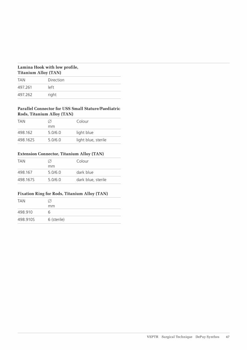
Lamina Hook with low profile, Titanium Alloy (TAN)
TAN Direction
497.261 left
497.262 right
Parallel Connector for USS Small Stature/Paediatric Rods, Titanium Alloy (TAN)
TAN B Colour mm
498.162 5.0/6.0 light blue
498.162S 5.0/6.0 light blue, sterile
Extension Connector, Titanium Alloy (TAN)
TAN B Colour mm
498.167 5.0/6.0 dark blue
498.167S 5.0/6.0 dark blue, sterile
Fixation Ring for Rods, Titanium Alloy (TAN)
TAN B mm
498.910 6
498.910S 6 (sterile)

41 DePuy Synthes VEPTR Surgical Technique
1. Aebi M, Thalgott JS, Webb JK (1998): AO ASIF Principles in Spine Surgery. Berlin: Springer.
2. Aebi M, Arlet V, Webb JK (2007) AOSPINE Manual (2 vols), Stuttgart, New York: Thieme.
Bibliography


0123
Synthes GmbHEimattstrasse 34436 OberdorfSwitzerlandTel: +41 61 965 61 11Fax: +41 61 965 66 00www.depuysynthes.com ©
DeP
uy S
ynth
es S
pine
, a d
ivis
ion
of S
ynth
es G
mbH
. 201
6.
All
right
s re
serv
ed.
036.
000.
421
DS
EM
/SP
N/1
215/
0398
11
/16
Not all products are currently available in all markets.
This publication is not intended for distribution in the USA.
All surgical techniques are available as PDF files at www.depuysynthes.com/ifu


