20
Surgical Technique Guide and Product Catalogue Cervical CFRP I/F CAGE ®

Surgical Technique
Guide and Product Catalogue
Cervical CFRP I/F CAGE®

A cervical interbody fusion device offering mechanical stability whilst facilitating bony fusion.
The CERVICAL CFRP I/F CAGE® is a carbon fibre reinforced polymer (CFRP) interbody fusion device with over 10 years clinical success1,2.
The Cage provides mechanical stability whilst facilitating optimal conditions for fusion, which can be visualised due to the radiolucent property of the biocompatible cage material.
The CERVICAL CFRP I/F CAGE distracts and maintains the intervertebral height, as well as providing
restoration of cervical lordosis. The range of cages available is based on natural anatomical variation.
I n t R o d u C t I o n

2
dEsIGn RAtIonAlE 3
FunCTIon oF AnTERIoR CERVICAL FusIon GRAFT 4
REsToRATIon And mAInTEnAnCE oF dIsC hEIGhT 5
sTAbIL ITy And FusIon 5
ImPLAnT dEsCRIPTIon 6
suRGICAl tEChnIquE 7
PosIT IonInG ThE PATIEnT 7
suRGICAL APPRoACh And ExPosuRE 8
mAkInG ThE InCIsIon 8
REmoVAL oF ThE dIsC And PREPARATIon oF ThE EndPLATEs 10
mEAsuRInG ThE APPRoPRIATE CERVICAL CFRP I /F CAGE 12
hARVEsTInG, PREPARATIon And InsERTIon oF ThE GRAFT
InTo ThE I /F CAGE 13
InsERTIon oF ThE I /F CAGE 13
CLosuRE oF ThE wound 14
PosT-oPERATIVE CARE 14
oRdERInG InFoRmAtIon 15
ImPLAnTs And InsTRumEnTATIon 15
CAsEs And TRAys 16
bonE GRAFT soLuTIons 17
C o n t E n t s

C E RV I C A L C F R P I / F C A G E
3
The fusion technique used in anterior cervical interbody fusion has gone
through many transformations, from the use of a tricortical iliac crest graft
as advocated by smith and Robinson3, to Cloward’s bicortical dowel-shaped
graft4. The CERVICAL CFRP I/F CAGE represents further advancement by
adopting the benefits of a mechanical device with the use of biologic bone
graft, resulting in a higher fusion success rate and increased pain relief1,2.
The CERVICAL CFRP I/F CAGE has been designed as an anterior solution to
cervical interbody fusion. It is indicated for the treatment of herniated cervical
discs and symptomatic cervical spondylosis. The cage has a dual function
to restore disc height in a load sharing environment and to restore cervical
lordosis, thus providing stability to the cervical spine.
A cervical interbody fusion device offering mechanical stability whilst facilitating bony fusion.

4
FunCtIon oF AntERIoR CERvICAl FusIon GRAFt
D E S I G N R AT I O N A L E
Any implant used for anterior cervical fusion has important mechanical
functions: it must achieve disc space distraction to prevent nerve root
impingement, it must support the weight of the head, and it must provide
long-term stability to the fused area in spite of continuing motion of adjacent
segments.
The CERVICAL CFRP I/F CAGE is a carbon fibre reinforced polymer implant,
designed to separate the mechanical and biological requirements of anterior
cervical fusion. The implant is filled with graft material for achievement
of bone healing and the advantage of improved sagittal plane alignment,
improved maintenance of disc space height5 and decreased bone graft donor
site morbidity.

C E RV I C A L C F R P I / F C A G E
5
REstoRAtIon And mAIntEnAnCE oF dIsC hEIGht
stAbIlIty And FusIon
disc height restoration is achieved with the correct selection and implantation
of the CERVICAL CFRP I/F CAGE. once in situ, it is a combination of cage
design and materials that ensures the maintenance of the disc height. The
cage must be strong enough to resist the level of loading (compressive
strength) as well as the cyclic nature of its application (fatigue strength).
Initial stability is achieved through the surface teeth that make contact with
the vertebral body end plates. As the graft incorporates, leading to bony
fusion, long-term stability is achieved1,2.
The open design of the CERVICAL CFRP I/F CAGE maximises the amount
of bone graft that can be packed into it without compromising the cage
strength. with a maximised area of contact between graft and end plate, the
fusion mass is also maximised, ensuring stability.
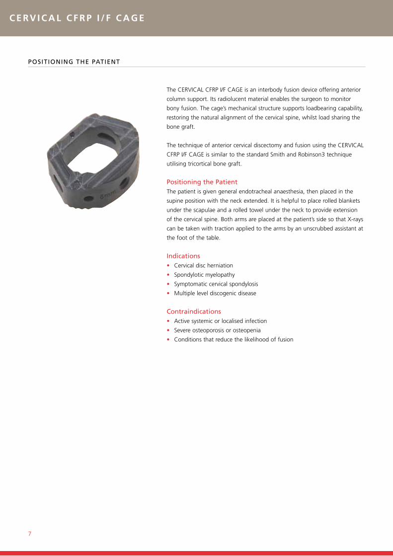
The CERVICAL CFRP I/F CAGE isavailable in a variety of sizes.
SURFACE TEETH increase stability,minimising risk of retropulsion.
The CERVICAL CFRP I/F CAGE packed withgraft prior to implantation.

Figure 1: CERVICAL CFRP I/F CAGE sizing
WIDTH
DEPT
H
Dimensions
Width Depth
Standard 15 mm 12 mm
Large 18 mm 14 mm
7˚
4, 5,6, 7or
8 mm
6
ImPlAnt dEsCRIPtIon
D E S I G N R AT I O N A L E
CERVICAL CFRP I/F CAGE implants (Figure 1) have a rounded trapezoidal shape to match the medial-lateral and anterior-posterior
dimensions appropriate for anterior cervical fusion. standard and large cages are available according to endplate size. To account
for disc height variations, each size is provided in heights of 4, 5, 6, 7 and 8 mm. The CERVICAL CFRP I/F CAGE has a shape
that includes an outer support structure and a hollow inner area, which is packed with autologous bone graft, usually harvested
from the iliac crest through a minimal “window” incision. Tooth-like serrations provide a stable interface when placed in the
intervertebral space. The cage features a taper of seven degrees from anterior to posterior, consistent with the physiological sagittal
plane alignment.
The structure of the implant has been shown to support all anticipated loads with a modulus of elasticity approximating that of
cortical bone6. As a result, the load is optimally shared between the cage and the graft, ensuring that the graft is not adversely
stress shielded. Tests of the CERVICAL CFRP I/F CAGE in the calf spine have shown it to be mechanically superior to reconstruction
using blocks of bone or methyl methacrylate7. The material is radiolucent so that bony healing can be assessed by normal
radiographic methods, while tantalum marker beads show implant position.
C E RV I C A L C F R P I / F C A G E
7
PosItIonInG thE PAtIEnt
The CERVICAL CFRP I/F CAGE is an interbody fusion device offering anterior
column support. Its radiolucent material enables the surgeon to monitor
bony fusion. The cage’s mechanical structure supports loadbearing capability,
restoring the natural alignment of the cervical spine, whilst load sharing the
bone graft.
The technique of anterior cervical discectomy and fusion using the CERVICAL
CFRP I/F CAGE is similar to the standard smith and Robinson3 technique
utilising tricortical bone graft.
Positioning the PatientThe patient is given general endotracheal anaesthesia, then placed in the
supine position with the neck extended. It is helpful to place rolled blankets
under the scapulae and a rolled towel under the neck to provide extension
of the cervical spine. both arms are placed at the patient’s side so that x-rays
can be taken with traction applied to the arms by an unscrubbed assistant at
the foot of the table.
Indications• Cervical disc herniation
• spondylotic myelopathy
• symptomatic cervical spondylosis
• multiple level discogenic disease
Contraindications• Active systemic or localised infection
• severe osteoporosis or osteopenia
• Conditions that reduce the likelihood of fusion

8
suRGICAl APPRoACh And EXPosuRE
mAkInG thE InCIsIon
S u R G I c A L T E c h N I q u E
The exposure can be made either on the left or right side according to
surgeon preference. Although risk of retraction injury to the recurrent
laryngeal nerve is higher from the right, a left sided approach has the
possibility of injuring the thoracic duct and is more likely to injure the
oesophagus. most right-handed surgeons prefer to approach from the right
side. A transverse “hemi-collar” incision is made parallel to the clavicle
extending from the sternocleidomastoid muscle to the midline (Figure 1).
The crico-thyroid membrane is at the C5-6 disc level. The incision is usually
two or three fingerbreadths above the clavicle, depending on vertebral level
desired. The incision is taken through the subcutaneous fat to the surface of
the platysma. Although some surgeons divide the platysma in line with the
skin incision, it is more cosmetic to elevate the skin a distance of two to three
centimetres on either side of the skin incision and divide the platysma in the
direction of its fibres, as shown in (Figure 2A).
| F I G u R E 1
| F I G u R E 2 A

C E RV I C A L C F R P I / F C A G E
9
The layer of deep cervical fascia is incised along the anterior border of the
sternocleidomastoid muscle (Figure 2b).
blunt dissection is used to develop the interval between the carotid sheath
and the midline structures, staying close to the trachea. The fascia along
the lateral edge of the superior belly of the omohyoid muscle is cut with a
metzenbaum (straight blunt scissors) until the edge of the oesophagus is
visible (Figure 2C).
The surgeon can use either a “peanut sponge”
or index finger to open the plane of cleavage
between the carotid sheath laterally and
the trachea and oesophagus in the midline
(Figure 2d), exposing the anterior cervical spine
| F I G u R E 2 d
Note: the diagonal fibres of the muscle.
| F I G u R E 2 C | F I G u R E 2 b
TrachealCartilage
RecurrentLaryngeal
Nerves
Longus ColiMuscle
Common CarotidArtery
SympatheticTrunk
Oesophagus
Vertebral Artery
ThyroidGland
VagusNerve
InternalJugular
Vein
Sternocleidomastoid
C-6
Cross-sectional view of the neck demonstrates the plane of cleavage between the carotid sheath laterally and the trachea and oesophagus medially.

10
REmovAl oF thE dIsC And PREPARAtIon oF thE EndPlAtEs
S u R G I c A L T E c h N I q u E
Cautery is used in the midline over the cervical spine, followed by a “peanut
sponge” to reflect the fascia and longus coli muscles (Figure 2E).
If desired, self-retaining retractors may be placed. The blunt-tooth blades are
placed medial-lateral, taking care that the teeth remain within the longus coli
muscle fibres. The smooth blades are placed superior-inferior.
A 22-gauge spinal needle is placed in the appropriate disc and a lateral x-ray
taken to verify anatomic level. If the needle has been pre-bent to a 90˚ angle
one centimetre from its tip, excessive penetration will be prevented.
with the correct level verified, 0.5ml of indigo carmine dye is injected into
the disc. This dye stains nuclear material blue and assists identification of
extruded disc fragments.
use of a Caspar or similar vertebral distractor is recommended to distract
across the disc space. small drill holes are placed in the vertebra above and
below the affected disc, just penetrating the cortex. The holes are tapped
and the long shank distraction screws are inserted, making sure that the
screw shanks are parallel. The distractor is applied, stretching the disc space
(Figure 3A).
| F I G u R E 2 E
| F I G u R E 3 A

C E RV I C A L C F R P I / F C A G E
| F I G u R E 3 b
Note: The osteophytes have been removed
on the patient’s left side and a nerve hook
verifies that the foramen is free. On the right
side, the osteophyte has not been removed
and the access to the spinal canal is limited.
| F I G u R E 3 C
11
Anterior osteophytes overlying the disc space may need to be removed using
a rongeur or osteotome. At times, these osteophytes add substantially to
the anterior-posterior dimension of the vertebral body. The anterior annulus
is incised and removed. The nucleus is removed with a pituitary rongeur or
curette. The cartilaginous endplate is peeled from the vertebral bodies above
and below using a small periosteal elevator or curette. dissection should not
be undertaken lateral to the upslope of Lushka’s joint on either side to assure
protection of the vertebral arteries. After the disc has been removed, greater
distraction can usually be achieved using the distractor.
while some surgeons have recommended that posterior osteophytes not be
removed due to increased risk of damage to the spinal cord8,9,10, Cloward4,11
and others have recommended that all posterior osteophytes be removed.
In cases of cervical spondylotic myelopathy, where removal of posterior
osteophyte formation is essential, performance of a corpectomy may be
preferred12,13. A tiny up-angled curette or kerrison rongeur can be used to
remove the posterior osteophytes, if necessary. This dissection can be carried
laterally until the neural foramen can be entered with a nerve hook to verify
that the nerve root is free and that all blue-stained nuclear material has been
removed, (Figure 3b). Vigorous probing into the foramen should be avoided
to prevent penetration of the vertebral artery.
The cage specific rasps (Figure 3C) are used to flatten the endplate and
ensure that all endplate cartilage has been removed. As recommended by
Robinson14, subchondral bone should be preserved as far as possible so that
it can function as a bearing surface for the implant.
Rasps

| F I G u R E 4 A
| F I G u R E 4 b
12
S u R G I c A L T E c h N I q u E
mEAsuRInG FoR thE APPRoPRIAtE CERvICAl CFRP I /F CAGE
The trials for the CERVICAL CFRP I/F CAGE (Figure 4A) are used to gauge the
selection of implant size.
Figure 4b shows the use of a trial for gauging both the height and the size
of the implant required, and to assure that each surface is flat and the space
is equally tapered from front to back. Each trial is slightly smaller than the
actual cage implant (0.75 mm) to allow the implant a snug fit.
Trials

C E RV I C A L C F R P I / F C A G E
| F I G u R E 5
| F I G u R E 6
13
InsERtIon oF thE I /F CAGE
hARvEstInG, PREPARAtIon And InsERtIon oF thE GRAFt Into thE I /F CAGE
The CERVICAL CFRP I/F CAGE is filled with autologous cancellous bone,
harvested from the iliac crest using the following technique. A 2 cm incision
is made over the rim of the iliac crest. The periosteum is incised with
electrocautery and elevated. An osteotome is used to remove a 1cm window
of outer cortex. A curette is used to remove sufficient cancellous bone to fill
the cage. The cortical window is replaced. The periosteum, subcutaneous
tissue and skin layers are closed with sutures of the surgeon’s choice. Filling
the CERVICAL CFRP I/F CAGE with a bone graft substitute may be preferred,
thus eliminating the need for bone graft harvest.
The selected cage is engaged with the threaded portion of the cage inserter
(Figure 5) and placed in the filler block.
using the cage filler block, the cancellous bone is packed firmly into the
hollow area of the cage. The cage is then gently tapped into the prepared
disc space (Figure 6) using the inserter designed to prevent driving the cage
too far posteriorly. under normal circumstances, the cage should be recessed
1 to 2 mm from the anterior cortex. A final x-ray is taken to verify position of
the implant.

| F I G u R E 7
14
S u R G I c A L T E c h N I q u E
ClosuRE oF thE Wound
Post-oPERAtIvE CARE
Absolute haemostasis must be achieved rior to closure. The vertebral body
distractor is removed along with the long shank distraction screws (Figure 7).
bone wax is placed in the screw holes. The anaesthetist is asked to move the
cervical spine through a range of flexion and extension positions, to insure
that stability has been achieved. An anterior cervical stabilization device can
be applied if less than optimum stability is observed.
A small drain is placed deep in the wound. The self-retaining retractors
are removed and the tissue layers closed. The platysma is usually the only
layer requiring suture. subcutaneous or subcuticular sutures are placed and
steri-strips applied to the skin. A soft cervical collar is applied.
The patient is usually placed in the surgical intensive care unit overnight
to observe for the unlikely but dangerous possibility of airway obstruction.
The patient is allowed to ambulate 24 hours post-operatively. The drain is
removed and the patient discharged when comfortable usually on the second
or third post-operative day. The patient is instructed to minimise motion of
the cervical spine and wear the soft collar for one month post-operatively.

C E RV I C A L C F R P I / F C A G E
15
standard Cages
Cat. No. Description Anterior Height
1733-01-104 CERVICAL I/F CAGE, Standard 4 mm
1733-01-105 CERVICAL I/F CAGE, Standard 5 mm
1733-01-106 CERVICAL I/F CAGE, Standard 6 mm
1733-01-107 CERVICAL I/F CAGE, Standard 7 mm
1733-01-108 CERVICAL I/F CAGE, Standard 8 mm
large Cages
Cat. No. Description Anterior Height
1733-01-204 CERVICAL I/F CAGE, Large 4 mm
1733-01-205 CERVICAL I/F CAGE, Large 5 mm
1733-01-206 CERVICAL I/F CAGE, Large 6 mm
1733-01-207 CERVICAL I/F Cage, Large 7 mm
1733-01-208 CERVICAL I/F Cage, Large 8 mm
standard Rasps
Cat. No. Description
2733-20-104 Standard Rasp, Size 4
2733-20-105 Standard Rasp, Size 5
2733-20-106 Standard Rasp, Size 6
2733-20-107 Standard Rasp, Size 7
2733-20-108 Standard Rasp, Size 8
large Rasps
Cat. No. Description
2733-20-204 Large Rasp, Size 4
2733-20-205 Large Rasp, Size 5
2733-20-206 Large Rasp, Size 6
2733-20-207 Large Rasp, Size 7
2733-20-208 Large Rasp, Size 8
ImPlAnts
IntRumEnts

16
O R D E R I N G I N f O R m AT I O N
standard trials
Cat. No. Description
2733-30-104 Standard Trial, Size 4
2733-30-105 Standard Trial, Size 5
2733-30-106 Standard Trial, Size 6
2733-30-107 Standard Trial, Size 7
2733-30-108 Standard Trial, Size 8
large trials
Cat. No. Description
2733-30-204 Large Trial, Size 4
2733-30-205 Large Trial, Size 5
2733-30-206 Large Trial, Size 6
2733-30-207 Large Trial, Size 7
2733-30-208 Large Trial, Size 8
miscellaneous
Cat. No. Description
2733-10-001 Cage Impactor
2733-10-200 CERVICAL I/F CAGE Filler Block
2733-10-002 Cancellous Bone Tamp
2733-10-100 CERVICAL I/F CAGE Inserter
CAsEs And tRAys
Cases and trays
Cat. No. Description
2733-30-010 European Cervical Instrument Tray

C E RV I C A L C F R P I / F C A G E
17
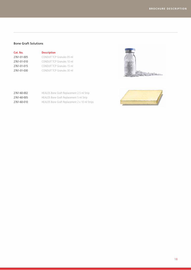
bonE GRAFt solutIons
• 3-dimensional, osteoconductive matrix constructed of cross-linked
type 1 collagen fibres, coated with non-crystal hydroxyapatite.
• strong affinity for osteoprogenitor cell attachment
and an ideal environment for the cellular proliferation
needed in the bone formation process.
• structural integrity and 95% porosity: 3-d cross-linked structure
provides excellent strength and a “shapememory” effect, retaining
its structural integrity and porosity, even when hydrated.
• Excellent graft handling characteristics: Flexible,
sponge-like strip moulds into place for complete graft site
coverage, even in irregular or uneven surfaces.
• ConduIT™ TCP Granules are made entirely of ß-TriCalcium
Phosphate, the porous, osteoconductive ceramic similar to
the mineral constituents of natural bone (i.e. 70%).
• The partially connected pore structure of ConduIT TCP Granules is
well-suited for cell-to-cell interaction, nutrition and vascularisation. Its high
degree of surface area provides a generous field for cellular attachment.
• 6-9 months resorption rate.
HEALOS® Bone Graft Replacement, just prior tohydration with bone marrow aspirate.
Hydrated, compacted HEALOSBone Graft Replacement.
“Shape memory” is retained in hydratedHEALOS Bone Graft Replacement, resulting
in excellent porosity within the site.
18
b r o c h u r e d e s c r i p t i o n
bone Graft solutions
Cat. No. Description
2761-01-005 ConduIT TCP Granules 05 ml
2761-01-010 ConduIT TCP Granules 10 ml
2761-01-015 ConduIT TCP Granules 15 ml
2761-01-030 ConduIT TCP Granules 30 ml
2761-60-002 HEALoS Bone Graft Replacement 2.5 ml Strip
2761-60-005 HEALoS Bone Graft Replacement 5 ml Strip
2761-60-010 HEALoS Bone Graft Replacement 2 x 10 ml Strips
Distributed in the USA by:DePuy Spine, Inc.325 Paramount driveRaynham, mA 02767usATel: +1 (800) 227 6633Fax: +1 (800) 446 0234
Authorized European Representative:DePuy International Ltdst Anthony’s RoadLeeds Ls11 8dTEnglandTel: +44 (0)113 387 7800Fax: +44 (0)113 387 7890
DePuy Spine EMEA is a trading division of DePuy International Limited. Registered Office: St. Anthony’s Road, Leeds LS11 8DT, EnglandRegistered in England No. 3319712
www.depuy.com
©DePuy Spine, Inc. 2011.All rights reserved.
*For recognized manufacturer, refer to product label.
Manufactured by one of the following:
DePuy Spine, Inc.325 Paramount driveRaynham, mA 02767-0350usA
DePuy Spine SÀRLChemin blanc 36Ch-2400 Le Locleswitzerland
medos International SÀRLChemin blanc 38Ch-2400 Le Locleswitzerland
0086
References:
1. Brooke nS, Rorke AW, King AT, Gullan RW: Preliminary experience of carbon fibre cage prostheses for treatment of cervical spine disorders. British Journal of neurosurgery. 11: 3, 221-227 (1997).
2. European CSRS, nice, France, June 5-7 1996 Logroscino and Specchia. 8 patients operated for cervical disc herniation. Minimum follow-up 1 year. Bony fusion achieved in 8/8 patients.
3. Robinson, RA, Smith, GW: The treatment of certain cervical spine disorders by anterior removal of the intervertebral disc and interbody fusion. JBJS 40: 607, (1958).
4. Cloward, RB: Vertebral body fusion for ruptured cervical discs. description of instruments and operative technique. Amer J Surg 98: 722-727, (1959).
5. Bartels RH, donk R, van Azn Rd, Height of cervical foramina after anterior discectomy and implantation of a carbon fibre cage. J neurosurg 95: 1 Suppl, 40-2, (2001).
6. Brantigan JW, Cunningham BW, McAfee PC, orbegoso CM, Wang H. Interbody lumbar fusion using a carbon fiber cage implant versus allograft bone. An investigational study in the Spanish goat. Spine. Jul 1; 19(13): 1436-44, (1994).
7. Brantigan, JW, Cunningham, BW, McAfee PC, Shono, Y: A biomechanical analysis of decompression and reconstruction methods in the cervical spine- emphasis on a carbon fiber composite. JBJS: in press.
8. Bohlman, HH: Cervical spondylosis with moderate to severe myelopathy. A report on seventeen cases treated by Robinson anterior cervical discectomy and fusion. Spine 2: 151-162, (1977).
9. Gore, dR, Sepic, SB: Anterior cervical fusion for degenerated or protruded discs. A review of one hundred forty-six patients. Spine 9: 667-671, (1984).
10. Stauffer, ES, Kraus, dR: Spinal cord injury as a complication of anterior cervical fusion. Clinical orthopoedics 112: 130, (1975).
11. Cloward, RB: The anterior surgical approach to the cervical spine. The Cloward procedure: past, present and future. Spine 13: 823, (1988).
12. Hayashi, H, Hosoya, K, oka, S, okada, K, Shirasaki, n,: Treatment of cervical spondylotic myelopathy by enlargement of the spinal canal anteriorly, followed by arthrodesis. JBJS 73A: 352-357, (1991).
13. Bohlman, HH, Zdeblick, TA, : Cervical kyphosis and myelopathy. Treatment by anterior corpectomy and strut grafting. JBJS 71A: 170-182, (1989).
14. Robinson, RA, Walker, AE, Ferlic, dC, Wiecking, dK: The results of anterior interbody fusion of the cervical spine. Journal 44A: 1569-1587, (1962).
EMEA: 9073-17-000 v2 12/11


