26
1 Surround Structured Lighting for Full Object Scanning Douglas Lanman, Daniel Crispell, and Gabriel Taubin Brown University, Dept. of Engineering August 21, 2007
1
Surround Structured Lighting for Full Object Scanning
Douglas Lanman, Daniel Crispell, and Gabriel TaubinBrown University, Dept. of EngineeringAugust 21, 2007

Surround Structured Lighting 2
Outline
Introduction and Related Work
System Design and Construction
Calibration and Reconstruction
Experimental Results
Conclusions and Future Work

Surround Structured Lighting 3
Review: Gray Code Structured Lighting
References: [8,9]
3D Reconstruction using Structured Light [Inokuchi 1984]Recover 3D depth for each pixel using ray-plane intersectionDetermine correspondence between camera pixels and projector planes by projecting a temporally-multiplexed binary image sequenceEach image is a bit-plane of the Gray code for each projector row/column
Point Grey Flea2(15 Hz @ 1024 x 768)
Mitsubishi XD300U(50-85 Hz @ 1024 x 768)

Surround Structured Lighting 4
Review: Gray Code Structured Lighting
References: [8,9]
3D Reconstruction using Structured Light [Inokuchi 1984]Recover 3D depth for each pixel using ray-plane intersectionDetermine correspondence between camera pixels and projector planes by projecting a temporally-multiplexed binary image sequenceEach image is a bit-plane of the Gray code for each projector row/columnEncoding algorithm: integer row/column index binary code Gray code
Point Grey Flea2(15 Hz @ 1024 x 768)
Mitsubishi XD300U(50-85 Hz @ 1024 x 768)

Surround Structured Lighting 5
Recovery of Projector-Camera Correspondences
3D Reconstruction using Structured Light [Inokuchi 1984]Our implementation uses a total of 42 images(2 to measure dynamic range, 20 to encode rows, 20 to encode columns)Individual bits assigned by detecting if bit-plane (or its inverse) is brighterDecoding algorithm: Gray code binary code integer row/column index
Recovered Rows Recovered Columns
References: [8,9]

Surround Structured Lighting 6
Overview of Projector-Camera Calibration
References: [11,12,13]
1
1
1
1
1
1
2
2
2 2
2
2
3
3
3 3
4
4
4
5
56
67
Camera Calibration ProcedureUses the Camera Calibration Toolbox for Matlab by J.-Y. Bouguet
Predicted Image-plane ProjectionDistorted Ray (4th-order radial + tangential)Normalized Ray
Estimated Camera Lens Distortion

Surround Structured Lighting 7
Overview of Projector-Camera Calibration
References: [11,12,13]
0.5
0.5 0.5
0.5
1
1 1
1
1.5
1.5 1.5
1.5
2
2 2
2
2.5
2.5 2.53
3 3
3
3.5 3.54 44.5 4.5
Estimated Projector Lens DistortionProjector Calibration ProcedureConsider projector as an inverse camera (i.e., maps intensities to 3D rays)Observe a calibration board with a set of fidicials in known locationsUse fidicials to recover calibration plane in camera coordinate systemProject a checkerboard on calibration board and detect cornersApply ray-plane intersection to recover 3D position for each projected cornerUse Camera Calibration Toolbox to recover intrinsic/extrinsic projector calibration using 2D→3D correspondences with 4th-order radial distortion

Surround Structured Lighting 8
Projector-Camera Calibration
References: [11,12,13]
0500
1000 0
500
1000
1500
400
200
0Xc2
Yc2
Oc2
Zc2
XpYp
Xc
ZpOpXc1
Zc1
Yc1
Oc1
(mm)
Zc (mm)
Y c(m
m)
Projector Calibration ProcedureObserve a calibration board with a set of fidicials in known locationsUse fidicials to recover calibration plane in camera coordinate systemProject a checkerboard on calibration board and detect cornersApply ray-plane intersection to recover 3D position for each projected cornerUse Camera Calibration Toolbox to recover intrinsic/extrinsic projector calibration using 2D→3D correspondences with 4th-order radial distortion

Surround Structured Lighting 9
Gray Code Structured Lighting Results

Surround Structured Lighting 10
Proposed Improvement: Surround Lighting
References: [1]
Limitations of Structured LightingOnly recovers mutually-visible surface(i.e., must be illuminated and imaged)Complete model requires multiple scans or additional projectors/camerasOften requires post-processing (e.g., ICP)
Proposed SolutionTrade spatial for angular resolutionMultiple views by including planar mirrorsWhat about illumination inference?
Use orthographic illumination
System ComponentsMulti-view: digital camera + planar mirrorsOrthographic: DLP projector + Fresnel lens

Surround Structured Lighting 11
Related Work
References: [2,3,4,7]
Multi-view using Planar MirrorsVisual Hull using mirrors [Forbes '06]Catadioptric Stereo [Gluckman '99]Mirror MoCap [Lin '02]
Orthographic ProjectorsRecent work by Nayar and Anand on volumetric displays using passive optical scatterers [SIGGRAPH '06]Introduces orthographic projectors
Structured Light for 3D ScanningOver 20 years of research [Salvi '04]Gray code sequences [Inokuchi '84]Recent real-time methods [Zhang '06]Including planar mirrors [Epstein '04]

Surround Structured Lighting 12
Outline
Introduction and Related Work
System Design and Construction
Calibration and Reconstruction
Experimental Results
Conclusions and Future Work

Surround Structured Lighting 13
Surround Structured Lighting Components
References: [1]
Mitsubishi XD300U Projector (1024x786)
Point Grey Flea2 Digital Camera (1024x786)
Manfrotto 410 Compact Geared Tripod Head
11''x11'' Fresnel Lens (Fresnel Technologies #54)
15''x15'' First Surface Mirrors
Newport Optics Kinematic Mirror Mounts
Surround Structured Lighting 14
Mechanical Alignment Procedure
References: [1]
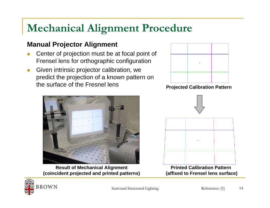
Manual Projector AlignmentCenter of projection must be at focal point of Frensel lens for orthographic configurationGiven intrinsic projector calibration, we predict the projection of a known pattern on the surface of the Fresnel lens Projected Calibration Pattern
Printed Calibration Pattern (affixed to Frensel lens surface)
Result of Mechanical Alignment(coincident projected and printed patterns)
Surround Structured Lighting 15
Mechanical Alignment Procedure
References: [1]
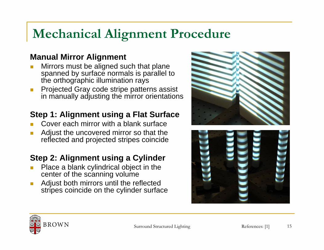
Manual Mirror AlignmentMirrors must be aligned such that plane spanned by surface normals is parallel to the orthographic illumination raysProjected Gray code stripe patterns assist in manually adjusting the mirror orientations
Step 1: Alignment using a Flat SurfaceCover each mirror with a blank surfaceAdjust the uncovered mirror so that the reflected and projected stripes coincide
Step 2: Alignment using a CylinderPlace a blank cylindrical object in the center of the scanning volumeAdjust both mirrors until the reflected stripes coincide on the cylinder surface

Surround Structured Lighting 16
Outline
Introduction and Related Work
System Design and Construction
Calibration and Reconstruction
Experimental Results
Conclusions and Future Work
Surround Structured Lighting 17
Orthographic Projector Calibration
References: [12]
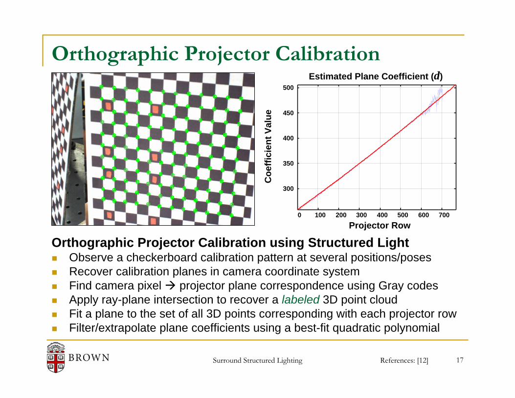
Orthographic Projector Calibration using Structured LightObserve a checkerboard calibration pattern at several positions/posesRecover calibration planes in camera coordinate systemFind camera pixel projector plane correspondence using Gray codesApply ray-plane intersection to recover a labeled 3D point cloudFit a plane to the set of all 3D points corresponding with each projector rowFilter/extrapolate plane coefficients using a best-fit quadratic polynomial
0 100 200 300 400 500 600 700
300
350
400
450
500
Projector Row
Coe
ffici
ent V
alue
Estimated Plane Coefficient (d)

Surround Structured Lighting 18
Planar Mirror Calibration
References: [1,7]
Ray ReflectionPoint ReflectionMirror Camera
Calibration ProcedureRecord planar checkerboard patterns(place against mirrors in two images)Find corners in real/reflected imagesSolve for checkerboard position/pose(also find initial mirror position/pose)Ray-trace through “reflected” cornersOptimize {RM1,TM1} to minimize back-projected checkerboard corner errorRepeat for second mirror {RM2,TM2}
Surround Structured Lighting 19
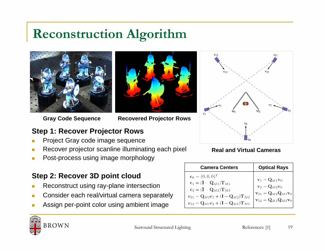
Gray Code Sequence
Reconstruction Algorithm
References: [1]
Step 1: Recover Projector RowsProject Gray code image sequenceRecover projector scanline illuminating each pixelPost-process using image morphology
Step 2: Recover 3D point cloudReconstruct using ray-plane intersectionConsider each real/virtual camera separatelyAssign per-point color using ambient image
Recovered Projector Rows
Real and Virtual Cameras
Optical RaysCamera Centers

Surround Structured Lighting 20
Outline
Introduction and Related Work
System Design and Construction
Calibration and Reconstruction
Experimental Results
Conclusions and Future Work

Surround Structured Lighting 21
Experimental Reconstruction Results
Ambient Illumination Gray Code Sequence Recovered Projector Rows

Surround Structured Lighting 22
Outline
Introduction and Related Work
System Design and Construction
Calibration and Reconstruction
Experimental Results
Conclusions and Future Work

Surround Structured Lighting 23
Conclusions and Future Work
Future WorkSub-pixel light-plane localizationEvaluate quantitative reconstruction accuracyApply post-processing to point cloud(e.g., filtering, implicit surface, texture blending)Increase the scanning volume“Flatbed” scanner configuration (i.e., no projector)Extend to real-time shape acquisition “in the round”
Primary AccomplishmentsExperimentally demonstrated Surround Structured LightingDeveloped a complete calibration procedure for prototype apparatus
Secondary AccomplishmentsProposed practical methods for orthographic projector construction/calibrationExtended Camera Calibration Toolbox for general projector-camera calibration
de Bruijn Pattern [Zhang '02]
References: [16]
Surround Structured Lighting 24
References3DIM 2007: Surround Structured Lighting1. D. Lanman, D. Crispell, and G. Taubin. Surround Structured Lighting for Full Object Scanning.
3DIM 2007.
Related Work: Orthographic Projectors and Structured Light with Mirrors2. S. K. Nayar and V. Anand. Projection Volumetric Display Using Passive Optical Scatterers.
Technical Report, July 2006.3. E. Epstein, M. Granger-Piché, and P. Poulin. Exploiting Mirrors in Interactive Reconstruction with
Structured Light. Vision, Modeling, and Visualization 2004.
Multi-view Reconstruction using Planar Mirrors4. K. Forbes, F. Nicolls, G. de Jager, and A. Voigt. Shape-from-Silhouette with Two Mirrors and an
Uncalibrated Camera. ECCV 2006.5. J. Gluckman and S. Nayar. Planar Catadioptric Stereo: Geometry and Calibration. In CVPR 1999.6. B. Hu, C. Brown, and R. Nelson. Multiple-view 3D Reconstruction Using a Mirror. Technical
Report, May 2005.7. I.-C. Lin, J.-S. Yeh, and M. Ouhyoung. Extracting Realistic 3D Facial Animation Parameters from
Multi-view Video clips. IEEE Computer Graphics and Applications, 2002.

Surround Structured Lighting 25
References3D Reconstruction using Structured Light8. J. Salvi, J. Pages, and J. Batlle. Pattern Codification Strategies in Structured Light Systems.
Pattern Recognition, April 2004.9. S. Inokuchi, K. Sato, and F. Matsuda. Range Imaging System for 3D Object Recognition.
Proceedings of the International Conference on Pattern Recognition, 1984.
Projector and Camera Calibration Methods10. R. Legarda-Sáenz, T. Bothe, and W. P. Jüptner. Accurate Procedure for the Calibration of a
Structured Light System. Optical Engineering, 2004.11. R. Raskar and P. Beardsley. A Self-correcting Projector. CVPR 2001.12. S. Zhang and P. S. Huang. Novel Method for Structured Light System Calibration. Optical
Engineering, 2006.13. J.-Y. Bouguet. Complete Camera Calibration Toolbox for Matlab.
http://www.vision.caltech.edu/bouguetj/calib_doc.
Visual Hull: Silhouette-based 3D Reconstruction14. A. Laurentini. The Visual Hull Concept for Silhouette-based Image Understanding. IEEE
Transactions on Pattern Analysis and Machine Intelligence, 1994.

Surround Structured Lighting 26
ReferencesReal-time Shape Acquisition15. S. Rusinkiewicz, O. Hall-Holt, and M. Levoy. Real-time 3D Model Acquisition. SIGGRAPH 2002.16. L. Zhang, B. Curless, and S. M. Seitz. Rapid Shape Acquisition using Color Structured Light and
Multi-pass Dynamic Programming. 3DPVT 2002.17. S. Zhang and P. S. Huang. High-resolution, Real-time Three-dimensional Shape Measurement.
Optical Engineering, 2006.


