Survey Of Watermarking Techniques And Applications Edin Muharemagic and Borko Furht Department of Computer Science and Engineering Florida Atlantic University, 777 Glades Road Boca Raton, FL 33431-0991, U.S.A. E-mail: {borko, edin}@cse.fau.edu 1 INTRODUCTION A recent proliferation and success of the Internet, together with availability of relatively inexpensive digital recording and storage devices has created an environment in which it became very easy to obtain, replicate and distribute digital content without any loss in quality. This has become a great concern to the multimedia content (music, video, and image) publishing industries, because technologies or techniques that could be used to protect intellectual property rights for digital media, and prevent unauthorized copying did not exist. While encryption technologies can be used to prevent unauthorized access to digital content, it is clear that encryption has its limitations in protecting intellectual property rights: once a content is decrypted, there’s nothing to prevent an authorized user from illegally replicating digital content. Some other technology was obviously needed to help establish and prove ownership rights, track content usage, ensure authorized access, facilitate content authentication and prevent illegal replication. This need attracted attention from the research community and industry leading to a creation of a new information hiding form, called Digital Watermarking. Basic idea is to create a metadata containing information about a digital content to be protected, and hide it within that content. The information to hide, the metadata, can have different formats. For example, it may be formatted as a character string or a binary image pattern, as illustrated in Figure 1-1. The metadata is first mapped into its bit stream representation, and then into a watermark , a pattern of the same type and dimension as the cover work , the digital content to be protected. The watermark is then embedded into the cover work. The embedded watermark should be imperceptible, and it should be robust enough to survive not only most common signal distortions, but also distortions caused by malicious attacks. Figure 1-1. General framework of digital watermarking systems It is clear that digital watermarking and encryption technologies are complementing each other, and that a complete multimedia security solution depends on both. This paper provides and overview of the image watermarking techniques and it describes various watermarking application scenarios.
Transcript
Survey Of Watermarking Techniques And Applications
Edin Muharemagic and Borko Furht Department of Computer Science and Engineering
A recent proliferation and success of the Internet, together with availability of relatively inexpensive digital recording and storage devices has created an environment in which it became very easy to obtain, replicate and distribute digital content without any loss in quality. This has become a great concern to the multimedia content (music, video, and image) publishing industries, because technologies or techniques that could be used to protect intellectual property rights for digital media, and prevent unauthorized copying did not exist.
While encryption technologies can be used to prevent unauthorized access to digital content, it is clear that encryption has its limitations in protecting intellectual property rights: once a content is decrypted, there’s nothing to prevent an authorized user from illegally replicating digital content. Some other technology was obviously needed to help establish and prove ownership rights, track content usage, ensure authorized access, facilitate content authentication and prevent illegal replication.
This need attracted attention from the research community and industry leading to a creation of a new information hiding form, called Digital Watermarking. Basic idea is to create a metadata containing information about a digital content to be protected, and hide it within that content. The information to hide, the metadata, can have different formats. For example, it may be formatted as a character string or a binary image pattern, as illustrated in Figure 1-1. The metadata is first mapped into its bit stream representation, and then into a watermark, a pattern of the same type and dimension as the cover work, the digital content to be protected. The watermark is then embedded into the cover work. The embedded watermark should be imperceptible, and it should be robust enough to survive not only most common signal distortions, but also distortions caused by malicious attacks.
Figure 1-1. General framework of digital watermarking systems
It is clear that digital watermarking and encryption technologies are complementing each other, and that a complete multimedia security solution depends on both. This paper provides and overview of the image watermarking techniques and it describes various watermarking application scenarios.
2
2 DIGITAL WATERMARKING TECHNIQUES
2.1 Digital Watermarking Systems
Digital watermarking system consists of two main components: watermark embedder and watermark detector, as illustrated in Figure 2-1. The embedder combines the cover work
OC , an original copy of digital media (image, audio, video), and the payload P, a collection of bits representing metadata to be added to the cover work, and creates the watermarked cover WC . The watermarked cover WC is perceptually identical to the original OC but with the payload embedded in. The difference between WC and OC is referred to as embedding distortion. The payload P is not directly added to the original cover OC . Instead, it is first encoded as a watermark W, possibly using a secret key K. The watermark is then modulated and/or scaled, yielding a modulated watermark mW , to ensure that embedding distortion will be small enough to be imperceptible.
Figure 2-1 Digital Watermarking Systems with Informed Detection
Before it gets to a detector, the watermarked cover WC may be subjected to different
types of processing yielding corrupted watermarked cover WC . This corruption could be caused either by various distortions created by normal signal transformations, such as compression, decompression, D/A and A/D conversions, or by distortions introduced by various malicious attacks. The difference between WC and WC is referred to as noise N.
Watermark detector either extracts the payload P from the corrupted watermarked cover
WC , or it produces some kind confidence measure indicating how likely it is for a given
payload P to be present in WC . The extraction of the payload is done with help of a watermark key K .
Watermark detectors can be classified into two categories, informed and blind, depending on whether the original cover work OC needs to be available to the watermark detection process or not. Informed detector, also known as a non-blind detector, uses the original cover work OC in a detection process. Blind detector, also known as an oblivious detector, does not need the knowledge of the original cover OC to detect a payload.
2.2 Watermarking as Communication
Watermarking system, as presented in the previous section, can be viewed as some form of communication. The payload message P, encoded as a watermark W , is modulated and transmitted across a communication channel to the watermark detector. In this model, the cover work OC represents a communication channel and therefore it can be viewed as
3
one source of noise. The other source of noise is a distortion caused by normal signal processing and attacks.
Modeling watermarking as communication is important because it makes it possib le to apply various communication system techniques, such as modulation, error correction coding, spread spectrum communication, matched filtering, and communication with side information, to watermarking.
Those techniques could be used to help design key building blocks of a watermarking system which deal with the following:
• How to embed and detect one bit
• What processing/embedding domain to use
• How to use side information to ensure imperceptibility
• How to use modulation and multiplexing techniques to embed multiple bits
• How to enhance robustness and security, where robustness can be defined as a watermark resistance to normal signal processing, and security can be defined as a watermark resistance to intentional attacks
2.3 Embedding One Bit in Spatial Domain
It is a common practice in communication to model channel noise as a random variable whose values are drown independently from a Normal distribution with zero mean and some variance, 2
nσ . This type of noise is referred to as Additive White Gaussian Noise (AWGN). It is also known from communication theory that the optimal method for detecting signals in the presence of AWGN is matched filtering, which is based on comput ing linear correlation between transmitted and received signals and comparing it to a threshold.
Figure 2-2. Watermark Embedding Procedure
Applying those two ideas to watermarking, yields a simple, spatial domain image watermarking technique with blind detection, which is illustrated in Figure 2-2. The watermark is created as an image having the same dimensions as the original cover image
OC with luminance values of its pixels generated as a key-based pseudorandom noise pattern drawn from a zero mean, unit variance Normal distribution, N(0,1). The watermark is then multiplied with the embedding strength factor s, and added to the luminance values of the cover image pixels. The embedding strength factor is used to impose a power cons traint in order to ensure that, once embedded, the watermark will not be perceptible. Note that, once the embedding strength factor s is selected, it is applied globally to all cover images that need to be watermarked. Also note that this embedding procedure creates the watermark W independently of the cover image OC .
According to the model of Digital Watermarking System depicted in Figure 2-1, the watermark detector will work on a received image C, which could be represented either
4
as NWCCC mOW ++== ˆ , if the image was watermarked, or as NCC O += otherwise, where N is a noise caused by normal signal processing and attacks.
To detect the watermark, a detector has to detect a presence of the signal W in the received, possibly watermarked image C. In other words, the detector has to detect the signal W in the presence of noise caused by OC and N. Assuming that both OC and N are AWGN, the optimal way of detecting watermark W in the received image C is based on computing the linear correlation between W and C, as:
∑⋅=⋅
⋅=
jiijijcw
JICW
JICWLC
,
11),( , (1)
where ijw and ijc represent pixel values at location i,j in W and C, and I and J represent the image dimensions.
If the received image C was watermarked, that is, if NWCC mO ++= , then:
)(1
),( NWWWCWJI
CWLC mO ⋅+⋅+⋅⋅
= (2)
Since we assumed that OC and N were AWGN, and we have created the watermark W as AWGN, the additive components of linear correlation OCW ⋅ , and NW ⋅ are expected to have small magnitudes, and the component WsWWW m ⋅=⋅ is expected to have much larger magnitude. This is illustrated in Figure 2-3, where it is shown that AWGNs generated as pseudorandom patterns using different keys (i.e. seeds) have very low correlation with each other, but high correlation with itself.
Figure 2-3. Correlation values for a pseudorandom pattern generated with seed=57 correlated
with pseudorandom patterns generated with other seeds
Therefore, if a calculated linear correlation ),( CWLC between the received image C and watermark W is small, then a conclusion can be made that the image C was not watermarked. Otherwise, the image C was watermarked. This decision is usually made based on a threshold T, so that if TCWLC <),( , the watermark W is not detected in C, and if TCWLC >),( , the watermark W is detected in C.
A watermark detection procedure based on threshold is illustrated in Figure 2-4. Two curves represent distribution of linear correlation (LC) values calculated for the set of un-marked images (the curve that peaks for the detection value 0), and for the set of watermarked images (the curve that peaks for the detection value 1). For a selected threshold value T, the portion of the curve for the un-marked images to the right of the threshold line T, represents all tested un-marked images which will be erroneously detected as marked images, and the portion of the curve for the marked images to the left of the threshold line T, represents watermarked images which will erroneously be declared as un-marked. The former error is called a false positive error, and the latter is called a false negative error. The false negative error rate can also be seen as a measure of efficiency of the watermarking system because it can be seen as a failure rate of the embedder to embed a detectable watermark.
5
False positive and false negative errors occur because original cover images CO are not accurately modeled as AWGN, and consequently they can have high correlation with the watermark signal W. Several proposed watermarking systems are based on this technique. [4][28][41][51][56].
Figure 2-4. Watermark Detection Procedure based on Linear Correlation: The left-hand curve represents distribution of LC values when no watermark has been embedded; The right-hand curve represents distribution of LC values when watermark was embedded
2.4 Patchwork: Another Spatial Domain Watermarking Technique
The Patchwork is another spatial domain watermarking technique designed to imperceptibly embed a single bit of information in a cover image [4]. It is a statistical method which embeds a watermark by changing statistical distribution of luminance values in the set of pseudo-randomly selected pairs of image pixels. This technique is based on an assumption that luminance values of an image have the following statistical property: ∑ ≈−
nii ba 0)( , where n
iaA 1}{= , and nibB 1}{= are two patches of pseudo-
randomly selected image pixels. A watermark is embedded by increasing brightness of pixels that belong to the patch n
iaA 1}{= , and accordingly decreasing brightness of pixels
that belong to the patch nibB 1}{= . In other words, after pseudo-randomly selecting
patches niaA 1}{= and n
ibB 1}{= , luminance values of the selected pixels are modified
according to the following formula: δδ −=∧+= iiii bbaa~~ . This modification
creates a unique statistic which indicates presence or absence of watermark. The watermark detector will select the same n pairs of pixels belonging to two patches and it will compute: ∑ −=∆
nii ba )
~~( . If δn2≈∆ , the image is watermarked; otherwise, it is
not.
This watermarking technique creates a watermark independently of the cover image, and it uses blind detection (i.e. the detector does not require the original cover image in order to be able to determine whether the image has been watermarked or not). The watermark detection is based on linear correlation because the detection process described above is equivalent to correlating the image with a pattern consisting of 1s and -1s, where the pattern contains a 1 for each pixel from the patch n
iaA 1}{= and a -1 for each pixel from
the patch nibB 1}{= .
2.5 Watermarking in Transform Domains
A watermark can be embedded into the cover image in a spatial domain, and we have described two such techniques earlier. Alternatively, a watermark embedding operation can be carried out in a transform domain, such as discrete Fourier transform (DFT)
6
domain, the full- image (global) discrete cosine transform (DCT) domain, the block-based DCT domain, the Fourier-Mellin transform domain, or the wavelet transform domain.
Transform domains have been extensively studied in the context of image coding and compression, and a lot of research results seem to be very applicable to digital watermarking. From theory of image coding we know that in most images the colors of neighboring pixels are highly correlated. Mapping into a specific transform domain, such as DCT or DWT, serves two purposes. It should de-correlate the original sample values and it should concentrate the energy of the original signal into just a few coefficients. For example, when a typical image is mapped into the spatial- frequency domain, the energy is concentrated in the low-index terms which are very large compared to the high- index terms. This means that a typical image is dominated by the low frequency components. Those low frequencies represent the overall shapes and outlines of features in the image, and its luminance and contrast characteristics. High frequenc ies represent sharp edges and crispiness in the image, but contribute little spatial- frequency energy. As an example, a typical image might contain 95% of the energy in the lowest 5% of the spatial frequencies of the two dimensional DCT domain. Retention of these DCT components, together with sufficiently many higher frequency components to yield an image with enough sharpness to be acceptable to the human eye, was the objective for creation of an appropriate quantization table to be used for JPEG compression.
As we’ll see in the next couple of sections, the selection of a specific transform domain to use for watermarking has its own reasons and advantages.
2.5.1 Watermarking in DCT Domain and Spread Spectrum Technique
DCT domain has been used extensively for embedding a watermark for a number of reasons. Using the DCT, an image is divided into frequency bands, and the watermark can be conveniently embedded in the visually important low to middle frequency bands. Sensitivities of the human visual system to changes in those bands have been extens ively studied in the context of JPEG compression, and the results of those studies can be used to minimize the visual impact of the watermark embedding distortion. Additionally, requirements for robustness to JPEG compression can be easily addressed because it is possible to anticipate which DCT coefficients will be discarded by the JPEG compression scheme. Finally, since JPEG/MPEG coding is based on a DCT decomposition, embedding a watermark in the DCT domain makes it possible to integrate watermarking with image/video coding and make real- time watermarking applications.
An efficient solution for watermarking in global DCT domain was introduced by Cox et. al. [15] and it is based on spread spectrum technology. General spread spectrum system spreads a narrow band signal over a much wider frequency band so that the signal to noise ratio (SNR) in a single frequency band is low and appears like noise to an outsider. However, a legitimate receiver with precise knowledge of the spreading function should be able to extract and sum up the transmitted signals so that the SNR of the received signal is strong.
Since, as we pointed out before, a watermarking system can be modeled as communication where the cover image is treated as noise and the watermark is viewed as a signal that is transmitted through it, it was only natural to try to apply techniques that
7
worked in communications to watermarking. The basic idea is to spread the watermark energy over visually important frequency bands, so that the energy in any one band is small and undetectable, making the watermark imperceptible. Knowing the location and content of the watermark, makes it possible to concentrate those many weak watermark signals into a single output with high Watermark to Noise Ratio (WNR). Here is a high-level overview of this watermarking technique.
The watermark is embedded in the first n lowest frequency components { }nicC 1= of a
full image DCT in order to provide high level of robustness to JPEG compression. The watermark consists of a sequence of real numbers { }n
iwW 1= drawn from a Normal distribution N(0,1), and it is embedded into the image using the formula )1(~
iii swcc += , where s is the watermark embedding strength factor. Watermark detection is performed using the following similarity measure:
'''
)',(WWWW
WWsim⋅
⋅= . (3)
The 'W is the extracted watermark, calculated as:
n
i
ini s
cc
w 11 }/)1~
{(}'{ −= , (4)
where ic~ components are extracted from the received, possibly watermarked image, and
ic components are extracted from the original cover image.
The watermark is said to be present in the received image if )',( WWsim is greater than the given threshold.
Since the original image is needed for calculation of the extracted watermark W’, which is used as part of the watermark presence test, this watermarking system falls into the category of systems with informed detectors.
The authors used an empirically determined value of 0.1 for the embedding strength factor s, and chose to spread the watermark across 1000 lowest frequency non-DC DCT coefficients (n=1000). Robustness tests showed that this scheme is robust to JPEG compression to the quality factor of 5%, dithering, fax transmission, printing-photocopying-scanning, multiple watermarking, and collusion attacks.
2.5.2 Watermarking in Wavelet Domain
With the standardization of JPEG-2000 and a decision to use wavelet-based image compression instead of DCT-based compression, watermarking techniques operating in the wavelet transform domain have become more attractive to the watermarking research community. The advantages of using the wavelet transform domain are an inherent robustness of the scheme to the JPEG-2000 lossy compression, and possibility of minimizing computation time by embedding watermarks inside of a JPEG-2000 encoder. Additionally, the wavelet transform has some properties that could be exploited by watermarking solutions. For example, wavelet transform provides multi- resolution representation of images, and this could be exploited to build more efficient watermark
8
detection schemes, where watermark detection starts from the low-resolution sub-bands first, and only if detection fails in those sub-bands, it explores the higher resolution sub-bands and additional coefficients it provides.
Zhu et al. [50] propose a unified approach to digital watermarking of images and video based on the two-dimensional (2-D) and three-dimensional (3-D) discrete wavelet transform. This approach is very similar to the Cox et al. [15] we presented above. The only difference is that Zhu generates a random vector with N(0,1) distribution and spreads it across coefficients of all high-pass bands in the wavelet domain as a multi-resolution digital watermark, where as Cox does it only across a small number of perceptually most important DCT coefficients. The watermark added to a lower resolution represents a nested version of the one corresponding to a higher resolution, and the hierarchical organization of the wavelet representation allows detection of watermarks at all resolutions except the lowest one. The ability to detect lower resolution watermarks reduces computational complexity of watermarking algorithms because fewer frequency bands are involved in computation. It also makes this watermarking scheme robust to image/video down sampling operation by power of two in either space or time.
2.5.3 Watermarking in DFT Domain
The discrete Fourier transform of an image is generally complex valued, and this leads to a magnitude and phase representation for the image. Most of the information about any typical image is contained in the phase, and the DFT magnitude coefficients convey very little information about the image [46].
Adding a watermark to the phase of the DFT, as it was proposed in [57], improves the robustness of the watermark because any modification of those visually important image components in an attempt to remove the watermark will significantly degrade the quality of the image. Another reason to modify/modulate the phase coefficients to add a watermark is based on communications theory which established that modulating phase is more immune to noise than modulating amplitude. Finally, authors also reported that the phase based watermarking was relatively robust to changes in image contrast.
Figure 2-5. Robustness to Geometric Transformations: Embed the watermark inside a new
workspace which is invariant to translation, rotation and scaling
Adding a watermark to the DFT magnitude coefficients and ignoring the phase was proposed in [46]. Embedding a watermark in the DFT magnitude coefficients which convey very little information about an image should not introduce a perceptible distortion. However, since modifications of the DFT magnitude coefficients are much less perceptible than phase modifications, one would expect that good image compressors would give much higher importance to preserving the DFT phase then the DFT magnitude, rendering the DFT magnitude based watermarking system vulnerable to image compression. The authors reported a surprising result that all major compression schemes (JPEG, SPIHT and MPEG) preserved the DFT magnitude coefficients as well as they preserved the DFT phase.
9
Another reason for using the DFT magnitude domain for watermarking is its translation or shift invariant property. A cyclic translation of an image in the spatial domain does not affect the DFT magnitude, and because of that the watermark embedded in the DFT magnitude domain will be translation invariant.
Image translation, as well as image scaling and rotation, generally do not affect a perceived image quality. However, translation or any other geometrical transformation de-synchronizes the image and thus makes the watermarks embedded using techniques described in the previous sections undetectable. To make the watermark detectible after a geometrical transformation has been applied to the watermarked image, the watermark needs to be synchronized, and synchronization process consists of an extensive search over a large space that covers all possible x, and y-axis translation offsets, all possible angles of rotation, and all possible scaling factors. An alternative to search for synchronization during watermark detection process was proposed in [39]. The basic idea is to avoid a need for synchronization search by transforming the image into a new workspace which is invariant to specific geometrical transformations, and embedding the watermark in that workspace. This is shown in Figure 2-5. The authors in [39] proposed embedding the watermark in the Fourier-Mellin transform domain which is invariant to translation, scaling and rotation. The Fourier-Mellin transform is computed by taking the Fourier transform of a log-polar map. A log-polar mapping is defined as:
)sin(
)cos(
θ
θµ
µ
ev
eu
=
= (5)
It provides one-on-one mapping between the 2),( ℜ∈vu , and )2,0(,),,( πθµθµ ∈ℜ∈ , and scaling and rotation in the (u,v) space convert into a translation in the ),( θµ space. The ),( θµ space is converted into the DFT magnitude domain to achieve translation invariance, and the watermark can be embedded in that domain, perhaps using one of techniques we described so far.
2.6 Watermarking With Side Information: Informed Embedding
The embedding components of the watermarking systems described so far create a watermark W independently of the cover CO. The embedder depicted in Figure 2-2, for example, pseudo-randomly generates the watermark pattern first, and then multiplies each watermark pixel value with a global embedding strength factor s, and adds it to the cover CO. The global embedding strength factor s is also selected independently of the cover CO and it is used to control a tradeoff between watermark robustness and its transparency or imperceptibility. Increasing the embedding strength factor s will increase the energy of the embedded watermark, resulting in higher robustness. However, it will also increase embedding distortion resulting in less transparent watermark and causing a loss of fidelity of the watermarked image CW compared to the original cover CO.
The embedder obviously has access to the original cover image CO in order to be able to embed the watermark into it. However, even though the embedder has access to the original cover image, the watermarking systems described so far did not take advantage of that information. In this section we will see how watermarking systems can use the information about the original cover image to improve watermark embedding
10
performance. This kind of watermarking systems are called watermarking systems with Informed Embedding, and their model is illustrated in Figure 2-6.
We will first look into how we could improve the effectiveness of the watermarking embedder depicted in Figure 2-2 by having the embedder take into consideration the original cover image and calculate the embedding strength factor s according to this information.
Figure 2-6 Digital Watermarking System with Informed Embedding and Blind Detection
We have seen that the original watermarking system was not 100% effective, because it had a non-zero false negative rate. Since a watermark was created independently of the cover image, it was to be expected that some cover images would interfere with the watermark in such a way that the embedded watermark would not be detectable. The informed embedding can be used to create a watermarking system which yields 100% effectiveness. This can be achieved by adjusting the embedding strength s for each individual cover image, so that every watermarked cover CW will have fixed-magnitude linear correlation with the watermark W. In other words the embedder will select the embedding strength factor s, to ensure that TCWLC W >),( is always correct.
Design of a watermarking system with informed embedding can be cast as an optimization problem which could be stated as follows: Given an original cover CO, select the embedding strength s to maximize specific important property, such as fidelity, robustness, or embedding effectiveness, while keeping the other property or properties fixed. For example, informed embedding can be used to improve robustness of the watermark while maintaining a fixed fidelity. The objective is to maximize the energy of the watermark signal, without increasing perceptible distortion of the watermarked signal. This can be done by taking advantage of imperfections of human visual system (HVS), and its inability to recognize all the changes equally. The characteristics of HVS and its sensitivities to frequency and luminance changes, as well as its masking capabilities have been captured into various perceptual models (i.e. models of HVS). Those models are then used as part of watermark embedding algorithms to help identify areas in the original cover image where the watermark embedding strength factor can be locally increased without introducing a perceptible change.
A lot of research has been done over the years to understand how HVS responds to frequency and luminance changes. The frequency sensitivity refers to the eye’s response to spatial, spectral, or time frequency changes. Spatial frequencies are perceived as patterns or textures, and spatial frequency sensitivity is usually described as the eye’s sensitivity to luminance changes [14]. It has been shown that an eye is the most sensitive to luminance changes in the mid-range spatial frequencies, and that sensitivity decreases at lower and higher spatial frequencies. The pattern orientation affects sensitivity as well and an eye is the most sensitive to vertical and horizontal lines and edges and it is the least sensitive to lines and edges with 45-degree orientation. Spectral frequencies are perceived as colors, and human eye is the least sensitive to changes in blue color.
11
Hurtung and Kutter [30] took into consideration color sensitivity of HVS, and proposed a solution where the watermark is added to the blue channel of an RGB image. Temporal frequencies are perceived as motion or flicker, and it has been demonstrated that eye sensitivity decreases very quickly as temporal frequencies exceed 30 Hz.
A number of solutions have been proposed where frequency sensitivity of HVS is exploited to ensure that the watermark is imperceptible. Those solutions use transform domain (e.g. DCT, DFT, Wavelet), and the watermark is added directly into the transform coefficients of the image. Even when a global embedding strength factor s, is used by the embedder, the watermark embedding algorithm can be changed to take into account local characteristics of the cover OC as follows. If { }iwW = is the watermark,
{ }iO cC = is the cover image, { }iW cC ~= is the watermarked image, and s represents the global embedding strength, then the embedder can embed the watermark using the following formula: )1(~
iii swcc += . Here, the amount of change is clearly dependant on characteristics of the cover image OC . Contrast that with the embedding formula
iii swcc +=~ we used before where the amount of change was the same irrespective of the magnitude of the ic coefficients.
More advanced embedding algorithms have been created by taking full advantage of characteristics of the HVS. For example, it is known that different spectral components may have different levels of tolerance to modification, and also it is known that the presence of one signal can hide or mask the presence of another signal. Those characteristics of the HVS can be exploited as well to create an efficient image-adaptive solution. A single embedding strength factor, s, will not be appropriate in that case. Instead, more general watermark embedding formula )1(~
iiii wscc += should be used. Different image-adaptive solutions select multiple scaling parameters is different ways. Walfgang et al. [52] present a couple of image-adaptive watermarking solutions.
2.7 Watermarking With Side Information: Informed Coding
Watermarking systems we described above use the cover information as part of the watermark embedding operation. The watermark W is created independently of the cover
OC , and then it is locally amplified or attenuated depending on the local characteristics of the cover OC and based on perceptual models of sensitivities and masking capabilities of HVS. Since the watermark W is created independently of the cover OC , it is clear that those algorithms do not take full advantage of all the side information about the cover OC available to the watermark embedder.
Instead of creating the watermark independently of the cover OC , and then modifying it based on local characteristics of the cover OC in an attempt to minimize interfe rence and distortion, the embedder can use the side information about the cover OC during the watermark encoding/creation process to choose between several available alternative watermarks and select the one that will cause the least distortion of the cover OC . This technique is referred to as Watermarking with Informed Coding.
12
Watermarking with Informed Coding was inspired by theoretical results published by Max Costa in his “Writing on Dirty Paper” report [13] on the capacity of a Gaussian channel having interference that is known to the transmitter. Costa described the problem using a dirty paper analogy, which could be stated as follows [14]: Given a sheet of paper covered with independent dirt spots having normally distributed intensity, write a message on it using limited amount of ink, and then send the paper on its way to a recipient. Along the way the paper acquires more normally distributed dirt. How much information can be reliably sent, assuming that the recipient cannot distinguish between ink and dirt. This problem is illustrated in the Figure 2-7.
Figure 2-7 Dirty-paper channel studied by Costa. There are two noise sources, both AWGN. The
encoder knows the characteristics of the first noise source (dirty paper or the original cover) before it selects (watermark) W
Costa showed that the capacity of his dirty-paper channel is given by:
)1(log21
22N
PC
σ+= (6)
where P represents the power constraint imposed on the transmitter (i.e. there was a limited amount of ink available to write a message), and 2
Nσ represents a variance of the second source of noise. Surprisingly enough, the first source of noise, the original dirt on the paper, does not have any effect on the channel capacity.
Costa’s dirty paper problem can also be viewed as watermarking system with blind detection. The message to be written is a watermark W, the message is written on (embedded in) the first coat of dirt, the Cover OC , the limited amount of ink can be interpreted as a power constraint that ensures fidelity, and the second noise source, n, represents distortions caused by normal signal processing and attacks. Since the dirty paper channel can be cast as a watermarking system, Costa’s results attracted a lot of attention in the watermarking research community because they established an upper bound for the watermark capacity and demonstrated tha t capacity does not depend on the interference caused by the cover OC .
The watermark systems inspired by Costa’s work are based on the following principle: Instead of having one watermark for each message, have several alternatives available (the more, the better), and select the one with minimum interference with the cover OC . Unfortunately, straightforward implementation of this principle is not practical. The problem is that both watermark embedder and watermark detector are required to find the closest watermark to a given vector representing possibly distorted cover OC , for every message/payload. For large number of messages and large number of watermarks for each message, computational time and storage requirements are simply too high.
As a solution to this problem we need to use watermarks that are structured in such a way as to allow efficient search for closest watermark to a given cover OC [25]. Quantizing to a lattice has been identified as an appropriate tool, and most of the work related to the
13
watermarking with informed coding is based on using lattice codes, where watermarks represent points in a regular lattice.
Figure 2-8 Quantization index modulation information embedding and detection
Chen and Wornell [11] have proposed watermark embedding based on that principle. Their method called quantization index modulation (QIM) is based on the set of N-dimensional quantizers, one quantizer for each possible message m that needs to be transmitted. The message to be transmitted determines the quantizer to use. The selected quantizer is then used to embed the information by quantizing the cover OC . The quantization of OC can be done in any domain (i.e. spatial, DCT, etc.). A distortion can be controlled by selecting an N-dimensional quantization point closest to the cover OC . In the decoding process, a distance metric is evaluated for all quantizers and the one with the smallest distance from the received image WC
~ identifies the embedded information.
This is illustrated in the Figure 2-8, for a one-dimensional case and two uniform, scalar quantizers representing two different messages, m1 and m2. Those two messages could be used to represent two distinct values of one bit: 0 and 1. The watermarking system based on QIM was shown to have better performance than other watermarking systems based on the standard spread-spectrum modulation which are not image-adaptive.
There are other possible ways to partition the space, and there are other possible ways to embed a watermark. For example, it is possible to embed a watermark by enforcing a desired relationship, as proposed by Koch at all [33]. This solution uses relationship between DCT coefficients to embed a watermark as follows: An image is partitioned into 8x8 blocks, and a pair of DCT coefficients is selected to represent a single bit in each block. Let’s say out of the set of DCT coefficients ),..,( 8811 aa , the selected pair is
),( mnij aa . The mutual relationship between two coefficients can then be used to represent
the value of one bit. For example, mnij aa < , can be interpreted as bit 1. The bit embedding process then consists of making appropriate changes to the pair of coefficients, if needed, to ensure that the relationship between coefficients is correct for the bit we want to embed. For example, assuming that the relationship mnij aa < represents bit value 1, the embedding algorithm can be described as follows: To embed a bit value 1 into the 8x8 block, check the relationship between coefficients in the pair. If
mnij aa < , nothing needs to be done since the relationship already indicates a correct bit value. Otherwise, modify coefficients appropriately to enforce desired relationship
mnij aa < . In order to strike the balance between robustness and possible image degradation caused by modifications of the coefficients, the pair is selected from mid-range frequencies. This approach shows good robustness to JPEG compression down to a quality factor of 50%.
2.8 Watermarking and Multi-bit Payload
A watermark designed to carry only one bit of information is typically created as a pseudo-random noise drown from Gaussian as we described earlier. The detector extracts
14
the embedded bit by verifying whether the watermark is present or not. Most watermarking applications, however, require more than one bit of information to be embedded.
The information rate of the watermarking system can be increased by introducing additional watermarks, and mapping each individual watermark to different bit string (multi-bit message). For example, to support 4-bit messages, one would need 162 4 = different watermarks, each one mapping to a different 4-bit message. The message is detected by computing a detection value for each of 16 watermarks, and selecting the one with the highest detection value. This technique is known as direct message coding. It works well for short messages, but it is not practical for longer bit strings. For example, in order to embed 16 bits of information, the watermarking system would need
65536216 = different watermarks. Those watermarks would have to be created with the maximum possible separation to avoid a situation where a small corruption of the watermarked image would lead to erroneous watermark detection. Ensuring that 65536 watermarks are far apart from one another is not easy. Additionally, the detector would have to compare a test image against 65536 different watermarks even if it only had to check for the watermark absence.
An alternative to direct message coding is a technique where a different watermark represents each individual bit of the multi-bit message. A multi-bit message can be embedded into a cover image by adding watermarks representing individual bits of the multi-bit message to the cover, one by one. This is the approach used in [33] we described before. More generally, this technique can be presented as the one where watermarks representing individual bits of a multi-bit message are first combined together into a single watermark representing the whole message, and then added into the cover image.
Watermarks can be combined together in a couple of different ways. For example, they could be tiled together in such a way that any individual tile is a watermark representing individual message bit. This is equivalent to the space division multiplexing. Alternatively, an approach equivalent to frequency division multiplexing could be used where watermarks representing individual message bits would be placed into disjoint frequency bands. Or, most generally, an approach analogous to code division multiplexing in spread spectrum communications could be used. In this approach each bit is spread across the whole image. The watermarks representing individual bits can be combined together without interfering with each other because they are selected to be mutually orthogonal.
2.9 Classification of Watermarking Systems
Watermarking systems can be classified according to many different criteria. For example, depending on whether a Watermark Embedder uses side information or not, watermarking systems can be categorized into the systems with Blind and Informed Embedders. The Informed Embedder category can further be divided into Embedders with Informed Embedding and with Informed Coding depending on whether side information is used to optimize watermark embedding operation of an independently generated watermark, or it is used to help select the most appropriate watermark for the
15
given Cover Work. Watermarking systems can also be categorized into systems with Informed and Blind Detectors, depending on whether the original Cover Work is needed in order to be able to detect the watermark. Other classifications are possible as well. Watermarking systems can be classified based on how a watermark gets merged with the Cover Work to create the Watermarked Cover, what technology is used to minimize perceptible distortion of the Watermarked Cover, whether watermarks are manipulated in spatial or transform domains, or based on how they implement support for multi-bit messages. The classification summary is shown in the Table 2-1.
Table 2-1 Classification of Watermarking Systems
2.10 Evaluation of Watermarking Systems
Once a watermarking system has been designed and implemented, it is important to be able to objectively evaluate its performance. This evaluation should be done in such a way to be able to compare results against other watermarking systems designed for the same or similar purpose [31][34][40].
By definition, watermarking is a technique for embedding a watermark into a cover work imperceptibly and robustly. Therefore a quality of a new watermarking system can be measured by, for example, evaluating those two properties and comparing results against an equivalent set of measures obtained by evaluating other watermarking systems. But, how does one objectively measure whether a distortion introduced by embedding a watermark is perceptible or not? This is actually not easy. As we’ll see, watermark imperceptibility can be evaluated either using subjective evaluation techniques involving human observers, or using some kind of distortion or distance metrics. The former cannot be automated and the later is not always dependable. Watermark robustness is easier to evaluate thanks to the existence of standardized benchmark tests. Those tests are designed to create various distortions to the watermarked cover under tests, so that it is possible to measure watermark detection rate under those conditions.
In addition to imperceptibility and robustness, watermarks have other properties that may need to be evaluated as well. We will address those later on, after we look into techniques one can use to evaluate watermark imperceptibility.
2.10.1 Evaluation of Imperceptibility
Imperceptibility of an embedded watermark can be expressed either as a measure of fidelity or quality. Fidelity represents a measure of similarity between the original and watermarked cover, whereas quality represents an independent measure of acceptability of the watermarked cover. The most accurate tests of fidelity and quality are subjective tests which involve human observers. Those tests have been developed by psychophysics, a scientific discipline whose goal is to determine relationship between the physical world and people’s subjective experience of that world. An accepted measure for evaluation of the level of distortion is a Just Noticeable Difference (JND), and it represents a level of distortion that can be perceived in 50% of experimental trials. One JND thus represents a minimum distortion that is generally perceptible.
16
Watermark perceptibility can be measured using different experiments developed as a result of various psychophysics studies. One example is the so called two alternative, forced choice test. In this procedure human observers are presented with a pair of images, one original and one watermarked, and they must decide which one has higher quality. Statistical analysis of responses provides some information about whether the watermark is perceptible. For example, if the fidelity of the watermarked image is high, meaning that it is very similar to the original, the random responses will be received and we’ll see approximately 50% of the observers selecting the original image as the higher quality one, and 50% of the observers selecting the watermarked image as the higher quality image. This result can be interpreted as zero JND. As we increase the watermark strength, the perceptible distortion will increase, and with that the ratio of observers identifying the original image as the higher quality one will increase as well. Once this ratio gets to 75%, we have reached a distortion equivalent to one JND. Variations of that test are possible, and more information about it can be found in [14]
Another, more general approach, allows observers more options in their choice of answers. Instead of selecting the higher quality image, observers are asked to rate the quality of the watermarked image under test. One example of quality scale that can be used to evaluate perceptibility of an embedded watermark is the one recommended by the ITU-R Rec.500, where a quality rating depends on the level of impairment a distortion creates. The recommended scale has 5 quality levels which go from excellent to bad, and those quality levels correspond to impairment descriptions which go from imperceptible distortion to very annoying distortion.
These subjective tests can provide very accurate measure of perceptibility of an embedded watermark. However, they can be very expensive to administer, they are not easily repeatable, and they cannot be automated.
An alternative approach is an automated technique for quality measure based on a model of human visual system (HVS). One such model was proposed by Watson [49].
The Watson’s model estimates the perceptibility of changes in terms of changes of individual DCT blocks, and then it pools those estimates into a single estimate of perceptual distance ),( WO CCD , where OC is the original image, and WC is a distorted version of OC .
The model has three components: sensitivity table, luminance masking and contrast masking. The sensitivity table, derived in [1], specifies the amount of change for each individual DCT coefficient that produces one JND. However, it is known that sensitivity to coefficient change depends on the luminance value, so that in bright background DCT coefficients can be changed by a larger amount before producing one JND. In other words, the bright background can mask more noise than the dark background. To account for this, Watson’s model adjusts the sensitivity table ijS for each block k, according to the block’s DC term, as follows:
α
⋅=
O
o
CkC
jiSkjiSL),0,0(
),(),,( , (7)
17
where ),0,0( kCO is the DC values of the thk block, α is a constant with a suggested
value of 0.649, and OC is the average of the DC coefficients in the image.
The third component of the model, the contrast masking, represents the reduction in visibility of change in one frequency due to the energy present in that frequency. The contrast masking is accounted for as follows:
where ),( jiv is a constant between 0 and 1 and may be different for each frequency coefficient. Watson uses a value of 0.7 for all ji, . The ),,( kjiSLC represents the amounts by which individual terms of the block DCT may be changed before resulting in one JND.
To compare the original image OC and a distorted image WC , the model first computes the difference between corresponding DCT coefficients,
),,(),,(),,( kjiCkjiCkjie OW −= , (9)
and then uses it to calculate the error in the thji, frequency of the block k as a fraction of one JND given by:
),,(
),,(),,(
kjiSLCkjie
kjid = (10)
Those individual errors are then combined, or pooled together into a single perceptual distance measure:
p
kji
pWO kjidCCD
1
,,
),,(),(
= ∑ , (11)
where Watson recommends a value of 4=p .
In general, modeling of HVS is very complex and the resulting quality metrics did not show clear advantage over simple distortion metrics so far [48].
The distortion metrics is yet another alternative. It is based on measuring distortion caused by embedding a watermark, and it is very easy to apply. The distortion can be represented as a measure of difference or distance between the original and the watermarked signal. One of the simplest distortion measures is the mean squared error (MSE) function defined as:
∑ −=N
owOW icicN
CCMSE 2])[][(1
),( . (12)
The most popular distortion measures are the Signal to Noise Ratio defined as:
∑ ∑ −=N N
WOoOW icicicCCSNR 22 ])[][(/][),( , (13)
and the Peak Signal to Noise Ration defined as:
18
∑ −=N
WooN
WO icicicCCPSNR 22 ])[][(/][max),( . (14)
For more detailed list of distortion measures see [31].
Distortion metric tests are simple and popular. Their advantage is that they do not depend on subjective evaluations. Their disadvantage is that they are not correlated with human vision. In other words, small distance between the original and the watermarked signal does not always guaranty high fidelity of the watermarked signal.
Wang and Bovik [48] have proposed a new quality metric called the Universal Image Quality Index. The index is calculated by modeling any image distortion as a combination of the following three factors: loss of correlation, luminance distortion and contrast distortion. The new index is mathematically defined, and it is not explicitly based on the HVS model. The authors claim that it performs significantly better than the widely used MSE distortion metric.
It is defined as:
))((
42222 yx
yxQ
yx
xy
++=
σσ
σ, (15)
where x is the original image, y is a distorted version of x, and
∑∑∑∑ −−
=−−
=== 2222 )(1
1,)(
11
,1
,1
yyN
xxN
yN
yxN
x iyixii σσ
2.10.2 Evaluation of Other Properties
Robustness property can be evaluated by applying various kinds of “normal” signal distortions and attacks that are relevant for the target application. The robustness can be assessed by measuring detection probability of the watermark after signal distortion. This is usually done using standardized benchmarking tests, and we’ll provide more information about it in the next section.
Reliability can be evaluated by assessing the watermark detection error rate. This can be done either analytically, by creating models of watermarking systems under test, or empirically, by running a number of tests and counting the number of errors. As we stated before, false positive and false negative errors are interrelated and it is not possible to minimize both probabilities (or error rates) simultaneously. Because of that those two errors should always be measured and presented together, for example using a receiver operating characteristics (ROC) curve.
Capacity is an important property because it has a direct negative impact on watermark robustness. Higher capacity (the amount of information being embedded) causes lower watermark robustness. Capacity can be assessed by calculating the ratio of capacity to reliability. This can be done empirically by fixing one parameter (e.g. payload size) and determining the other parameter (e.g. error rate). Those results can then be used to estimate the theoretical maximum capacity of the watermarking system under consideration. Since a requirement for capacity depends on the application, the question is how important it is to estimate the excess capacity capability of the watermarking
19
system under consideration. It may be important because the excess capacity can be traded for improvements in reliability. This can be done by using the excess payload bits for error detection and/or correction.
Another property that may need to be taken into consideration is the watermark access unit or granularity. It represents the smallest part of an audiovisual signal needed for reliable detection of a watermark and extraction of its payload. In the case of image watermarking for example, this property can be evaluated by using test images of different sizes.
In general, in order to obtain statistically valid results, it is important of ensure that a/ the watermarking system under consideration is tested using a large number of test inputs, b/ the set of test inputs is representative of what is expected in the operating environment (application), and c/ the tests are executed multiple times using different watermarking keys.
2.10.3 Benchmarking
There are a number of benchmarking tools which have been created to standardize watermarking system evaluating processes.
Stirmark is a benchmarking tool for digital watermarking designed to test robustness. For a given watermarked input image, Stirmark generates a number of modified images which can then be used to verify if the embedded watermark can still be detected. The following image alterations have been implemented in Stirmark Version 3.1: Cropping, Flip, Rotation, Rotation-Scale, FMLR, sharpening, Gaussian filtering, Random bending, linear transformations, Aspect ratio, Scale changes, Line removal, Color reduction, JPEG compression. More information about is can be found at: www.watermarkingworld.org.
Checkmark is a benchmarking suite for digital watermarking developed on Matlab under UNIX and Windows. It has been recognized as an effective tool for evaluation and rating of watermarking systems. Checkmark offers some additional attacks not present in Stirmark. Also, it takes the watermark application into account which means that the scores from individual attacks are weighted according to their importance for a given watermark purpose. The following image alterations have been implemented: Wavelet compression (jpeg 2000 based on Jasper), Projective transformations, Modeling of video distortions based on projective transformations, Warping, Copy, Template removal, Denoising (midpoint, trimmed mean, soft and hard thresholding, wiener filtering), Denoising followed by perceptual remodulation, Non- linear line removal, and Collage. More information about is can be found at: http://watermarking.unige.ch/Checkmark/
Optimark is a benchmarking tool developed to address some deficiencies recognized in Stirmark 3.1. Some of its features are: graphical user interface, detection performance evaluation using multiple trials utilizing different watermarking keys and messages, ROC curve, detection and embedding time evaluation, payload size evaluation, and so on. More information about is can be found at: http://poseidon.csd.auth.gr/optimark.
Certimark is a benchmarking suite developed for watermarking of visual content and a certification process for watermarking algorithms. It has been created as a result of a
20
large research project funded by European Union. More information about is can be found at: www.certimark.org.
3 APPLICATIONS OF DIGITAL WATERMARKING Very frequently there’s a need to associate some additional information with a digital content, such as music, image or video. For example, copyright notice may need to be associated with an image to identify a legal owner of that image. Or a serial number may need to be associated with a video to identify a legitimate user of that video. Or some kind of identifier may need to be associated with a song to help find a database where more information about it can be obtained from. This additional information can be associated with a digital content by placing it in the header of a digital file, or for images, it can be encoded as a visible notice. Storing information in the header of a digital file has a couple of disadvantages. First, it may not survive a file format conversion, and second, once an image is displayed or printed, its association with the header file and information stored in it is lost. Adding a visible notice to an image may not be acceptable if it negatively affects the esthetics of the image. This could be corrected to some extent by making the notice as small as possible and/or moving it to a visually insignificant portion of the image, such as the edge. However, once on the edge, this additional information can easily be cropped off, either intentionally or unintentionally.
Figure 3-1 The Lena image used as a test image on the left, and the cropped part of the original image which identifies the copyright owner, Playboy Enterprises, Inc. on the right.
This is exactly what happened with an image of Lena Soderberg after its copyright notice was cropped off. The image was originally published as a Playboy centerfold in November 1972. After the image has been scanned for use as the test image, most of it has been cropped including the copyright notice which was printed on the edge of the image. The “Lena” image became probably the most frequently used test image in image processing research, and appeared in a number of journal articles without any reference to its rightful owner, Playboy Enterprises, Inc.
Digital watermarking seems to be the suitable method for associating this additional information, the metadata, with a digital work. The metadata is imperceptibly embedded as a watermark in a digital content, the cover work, and it becomes inseparable from it. Furthermore, since watermarks will go through the same transformations as the cover work they are embedded in, it is sometimes possible to learn whether and how the content has been tampered with by looking into the resulting watermarks.
3.1 Classification of Digital Watermarking Applications There are a number of different watermarking application scenarios, and they can be classified in a number of different ways. The following classification is based on the type of information conveyed by the watermark [38].
Table 3-1 Classes of watermarking applications
21
In the following section we’ll provide a more detailed explanation of possible application scenarios involving watermarking.
3.2 Digital Watermarking for Copyright Protection Copyright protection appears to be one of the first applications digital watermarking was targeted for. The metadata in this case contains information about the copyright owner. It is imperceptibly embedded as a watermark in the cover work to be protected. If users of digital content (music, images, and video) have an easy access to watermark detectors, they should be able to recognize and interpret the embedded watermark and identify the copyright owner of the watermarked content.
An example of one commercial application created for that purpose is Digimarc Corporation ImageBridge Solution. The ImageBridge watermark detector is made available in a form of plug- ins for many popular image processing solutions, such as Adobe PhotoShop or Corel PhotoPaint. When a user opens an image using Digimark enabled application, Digimarc’s watermark detector will recognize a watermark. It will then contact a remote database using the watermark as a key to find a copyright owner and his contact information. An honest user can use that information to contact the copyright owner to request permission to use the image.
We have shown above how an invisibly embedded watermark can be used to identify copyright ownership. It would be nice if an embedded watermark could be used to prove the ownership as well, perhaps even in a court of law. We can envision the following scenario: A copyright owner distributes his/her digital content with his/her invisible watermark embedded in it. In the case of a copyright ownership dispute, a legal owner should be able to prove his ownership by demonstrating that he owns the original work, and that the disputed work has been derived from the original by embedding a watermark into it. This could be done by producing the original work together with the watermark detector, and having detector detect the owner’s watermark in a disputed work. Unfortunately, it appears that the above scenario can be defeated under certain assumptions, and because of that watermarking has not been accepted yet as a technology dependable enough to be used to prove the ownership. One potential problem is related to the availability of watermark detector. It has been demonstrated that if a detector is widely available, then it is not possible to protect watermark security. In other words, if a detector is available, it is always possible to remove an embedded watermark. This can be achieved by repeatedly making imperceptible changes to the watermarked work, until a watermark detector fails to detect the watermark. Once the watermark is removed, the original owner will not be able to prove his ownership any longer. Even if the original watermark cannot be removed, Craver et al. [19][20][21] demonstrated that, under certain conditions, it is possible to add another watermark to an already watermarked image in such a way as to make it appear that this second watermark is present in all copies of disputed image, including the original image. This is known as an ambiguity attack, and it could be used not only to dispute the ownership claims of the rightful copyright owner, but also to make new ownership claim to the original digital content
22
3.3 Digital Watermarking for Copy Protection The objective of a copy protection application is to control access to and prevent illegal copying of copyrighted content. It is an important application, especially for digital content, because digital copies can be easily made, they are perfect reproductions of the original, and they can easily and inexpensively be distributed over the Internet with no quality degradation.
There are a number of technical and legal issues that need to be addressed and resolved in order to create a working copy protection solution. Those issues are difficult to resolve in open systems, and we are not aware of the existence of an open system copy protection solution. Copy protection is feasible in closed, proprietary systems, and we will describe one proprietary solution, the Digital Versatile Disk (DVD) copy protection solution [5].
DVD copy protection system has a number of components designed to provide copy protection at several levels. The Content Scrambling System (CSS) encrypts MPEG-2 video and makes it unusable to anyone who does not have a decoder and a pair of keys required to decrypt it. But, once the video has been decrypted, CSS does not provide any additional protection for the content.
Additional mechanisms have been put in place to provide extra protection for the decrypted (or unscrambled) video. For example, the Analog Protection System (APS) prevents an unscrambled video displayed on television from being recorded on an analog device, such as VCR. APS does it by modifying NTSC/PAL signals in such a way that video can still be displayed on television but it cannot be recorded on VCR.
There was also a need to support limited copying of video content. For example, a customer should be able to make a single copy of the broadcast video for later viewing (a.k.a. time shifting recording), but he should not be able to make additional copies. The Copy Control Management System (CCMS) has been designed to provide that level of copy control by introducing and supporting three rules for copying: Copy_Free, Copy_Never, and Copy_Once. Two bits are needed to encode those rules, and the bits are embedded into the video frames in the form of watermarks.
Figure 3-2 DVD copy protection systems with watermarking.
It is obvious that this copy control mechanism will work only if every DVD recorder contains a watermark detector. The problem is how to ensure that every DVD recorder will have the watermark detector, since there does not seem to exist a natural economic incentive for DVD manufacturers to increase a production cost of their product by incorporating watermark detectors in DVD recorders. After all, a perceived market value of a DVD recorder with a watermark detector may be lower compared with a recorder without it, because a customer would rather have a device that can make illegal copies.
One solution to this problem could be to force DVD manufacturers to add watermark detectors in their devices by law. Since such a law does not exist, and even if it did, it would be very difficult to enforce it across every country in the world, an alternative solution was needed. The solution that has been adopted for DVD systems is based on the patent license. Basically, the DVD encryption patent license makes it mandatory to use watermark detectors in the patent compliant devices.
23
The patent- license approach ensures that compliant devices will use watermark detectors and prevent illegal copying, but it also makes it legal to manufacture noncompliant devices, the devices which do not implement the patented decryption, and therefore do not have to implement a watermark detector. Consequently, the DVD copy control mechanism does not prevent all possible illegal copying.
Interaction of encryption and copy control, combined with the playback control, a mechanism which allows a DVD compliant device to detect illegal copies, is used to create a solution where only illegal copies can be played on noncompliant devices, and only legal copies can be played on compliant devices, as illustrated by Figure 3-2. The objective of this scheme is to insure that one device will not be able to play both legal and illegal content. If a customer wants to play both lega l and illegal copies he will have to purchase both compliant and noncompliant devices. However, if one of the two has to be selected, the hope is that most customers will choose a compliant one.
3.4 Digital Watermarking for Fingerprinting There are some applications where the additional information associated with a digital content should contain information about the end user, rather than about the owner of a digital content. For example, consider what happens in a film making environment. During the course of film production, the incremental results of work are usually distributed each day to a number of people involved in a movie making activity. Those distributions are known as film dailies, and they are confidential. If a version is leaked out, the studio would like to be able to identify the source of the leak. The problem of identifying the source of a leak can be solved by distributing slightly different copies to each recipient, thus uniquely associating each copy with a person receiving it.
As another example, consider a digital cinema environment, an environment where films are distributed to cinemas in digital format instead of via express mail in the form of celluloid prints. Even though digital distribution of films could be more flexible and efficient and less expensive, film producers and distributors are slow to adopt it because they are concerned about potential loss of revenue caused by illegal copying and redistribution of films. Now, if each cinema receives a uniquely identifiable copy of a film, then, if illegal copies have been made, it should be possible to associate those copies with the cinema where they have been made, and initiate an appropriate legal action against it.
Associating unique information about each distributed copy of digital content is called fingerprinting, and watermarking is an appropriate solution for that application because it is invisible and inseparable from the content. This type of application is also known as traitor tracing because it is useful for monitoring or tracing illegally produced copies of digital work. Also, since watermarking can be used to keep track of multiple transactions that have taken place in the history of the copy of a digital content, the term transaction tracking has been used as well.
3.5 Digital Watermarking for Content Authentication Multimedia editing software makes it easy to alter digital content. For example, Figure 3-3 shows three images. The left one is the original, authentic image. The middle one is the modified version of the original image, and the right one shows the image region
24
which has been tampered. Since it is so easy to interfere with a digital content, there’s a need to be able to verify integrity and authenticity of the content.
A solution to this problem could be borrowed from cryptography, where digital signature has been studied as a message authentication method. Digital signature essentially represents some kind of summary of the content. If any part of the content is modified, its summary, the signature, will change making it possible to detect that some kind of tampering has taken place. One example of digital signature technology being used for image authentication is the trustworthy digital camera described in [26].
Digital signature information needs to be somehow associated and transmitted with a digital content it was created from. Watermarks can obviously be used to achieve that association by embedding signature directly into the content. Since watermarks used in the content authentication applications have to be designed to become invalid if even slight modifications of digital content take place, they are called fragile watermarks.
Fragile watermarks, therefore, can be used to confirm authenticity of a digital content. They can also be used in applications where it is important to figure out how digital content was modified or which portion of it has been tampered with. For digital images, this can be done by dividing an image into a number of blocks and creating and embedding a fragile watermark into each and every block.
Figure 3-3 Original image, tampered image, and detection of tampered regions.
Courtesy of D. Kirovski’s PowerPoint presentation.
Digital content may undergo lossy compression transformation, such as JPEG image conversion. While resulting JPEG compressed image still has an authentic content, the image authenticity test based on the fragile watermark described above will fail. Semi-fragile watermarks can be used instead. They are designed to survive standard transformations, such as lossy compression, but they will become invalid if a major change, such as the one in Figure 3-3, takes place.
3.6 Digital Watermarking for Broadcast Monitoring Many valuable products are regularly broadcast over the television network: news, movies, sports events, advertisements, etc. Broadcast time is very expensive, and advertisers may pay hundreds of thousands of dollars for each run of their short commercial that appears during commercial breaks of important movies, series or sporting events. The ability to bill accurately in this environment is very important. It is important to advertisers who would like to make sure that they will pay only for the commercials which were actually broadcast. And, it is important for the performers in those commercials who would like to collect accurate royalty payments from advertisers.
Broadcast monitoring is usually used to collect information about the content being broadcast, and this information is then used as the bases for billing as well as other purposes. A simple way to do monitoring is to have human observers watch the broadcast and keep track of everything they see. This kind of broadcast monitoring is expensive, and it is prone to errors. Automated monitoring is clearly better. There are two categories of automated monitoring systems: passive and active. Passive monitoring systems
25
monitor the content being broadcast and make an attempt to recognize it by comparing it with the known content stored in a database. They are difficult to implement for a couple of reasons. It is difficult to compare broadcast signals against the database content, and it is expensive to maintain and manage a large database of content to compare against. Active monitoring systems rely on the additional information which identifies the content and gets broadcast together with the content itself. For analog television broadcast, this content identification information can be encoded in the vertical blanking interval (VBI) of the video signal. The problem with this approach is that it is suitable for analog transmission only, and even in that case it may not be reliable because, in the USA, content distributors do not have to distribute information embedded in the VBI.
A more appropriate solution for active monitoring is based on watermarking. The watermark containing broadcast identification information gets embedded into the content itself, and the resulting broadcast monitoring solution becomes compatible with broadcast equipment for both digital and analog transmission.
3.7 Digital Watermarking for System Enhancement Digital watermarking can also be used to convey side-channel information with the purpose of enhancing functionality of the system or adding value to the content it is embedded in. This type of applications, where a device is designed to react to watermark for the benefit of the user, is also referred to as device control applications [14].
An example of an early application of watermarking for system enhancement is described in the Ray Dolby’s patent application filed in 1981, where he proposed to make radio devices which would turn Dolby FM noise reduction control system on and off automatically, in response to an inaudible signal broadcast within the audio frequency spectrum. Such a signal constitutes a simple watermark, and the proposed radio device was an enhancement compared to the radio devices used at that time, where listeners had to manually turn their radio’s Dolby FM decoder on and off.
More recently, Philips and Microsoft have demonstrated an audio watermarking system for music. Basically, as music is played, a microphone on a PDA can capture and digitize the signal, extract the embedded watermark and based on information encoded in it, identify the song. If a PDA is network connected, the system can link to a database and provide some additional information about the song, including information about how to purchase it.
Another example of a similar application is Digimarc MediaBridge system. On content production side, watermarks representing unique identifiers are embedded into images, and then printed and distributed in magazines as advertisements. On the user side, an image from a magazine is scanned, the watermark is extracted using the MediaBridge software, and the unique identifier is used to direct a web browser to an associated web site.
4 CONCLUSIONS
In this paper we presented an overview of digital watermarking. First we looked into various watermarking techniques. We presented a general model of the watermarking system, and identified its two main components: embedder and detector. Depending on
26
whether the original content was needed for detection, we classified watermarking systems into blind or informed detectors. We drew a parallel between a watermarking system and communications, and recognized a possibility to apply various communications system techniques to watermarking. In the overview of watermarking techniques, we introduced various watermarking system solutions for embedding a single bit in different domains, spatial, global and block DCT, Wavelet, and discrete Fourier domains. Those systems were based on blind embedding, where the watermark is both created and modulated independently of the original cover. We then presented improvements that could be achieved if the side information about the original cover is used by the embedder. Those systems have been divided into two groups. The first group represents watermarking systems that use informed embedding. Those systems create watermarks independently of the original cover, but they use the original cover information in the watermark modulation process trying to maximize the watermark energy without increasing perceptual distortion of the watermarked cover. The second group represents watermarking systems that use informed coding. Those systems do not generate watermark independently of the original cover. Instead, they use the original cover information to select one watermark, out of a set of available watermarks, which creates the least amount of distortion, and causes the least interference with the original cover. We then discussed the issues related to embedding multi-bit payloads, as well as issues related to the evaluation of watermarking systems. Then we looked at the range of applications that could benefit from applying digital watermarking technology. Protection of intellectual property is very important nowadays because digital multimedia content can be copied and distributed quickly, easily, inexpensively, and with high quality. Watermarking has been accepted as a complementary technology to multimedia encryption, providing some additional level of protection of intellectual property rights. Other applications, such as fingerprinting, content authentication, copy protection and device control have also been identified.
5 REFERENCES
[1] Ahumada, A. J. Jr; Peterson, H. A.; “Luminance-model-based DCT quantization for color image compression,” Human Vision, Visual Processing, and Digital Display III, Pages 365--374, 1992
[2] Arnold, M.; Schmucker, M; Wolthusen, S.D.; “Techniques and Applications of Digital Watermarking and Content Protection,” Artech House, 2003.
[3] Bell, A.E.; “The dynamic digital disk,” IEEE Spectrum, Volume: 36 Issue: 10 , Oct. 1999, Pages: 28 -35
[4] Bender, W.; Gruhl, D.; Morimoto, N.; Lu A., ”Techniques for Data Hiding,” IBM Systems Journal, Volume 35, Number 3&4, Pages: 313-336, 1996.
[5] Bloom, J.A.; Cox, I.J.; Kalker, T.; Linnartz, J.-P.M.G.; Miller, M.L.; Traw, C.B.S.; “Copy Protection for DVD Video,” Proceedings of the IEEE , Volume: 87, Issue: 7, July 1999, Pages: 1267 -1276.
[9] Chen, B.; Sundberg, C.-E.W.; “Digital audio broadcasting in the FM band by means of contiguous band insertion and pre-canceling techniques,” IEEE Transactions on Communications, Volume: 48 Issue: 10 , Oct. 2000, Pages: 1634 -1637
[10] Chen, B.; Wornell, G.W.; “An information-theoretic approach to the design of robust digital watermarking systems,” Proceedings of IEEE International Conference on Acoustics, Speech, and Signal Processing, March 1999. Volume: 4 , Pages: 2061 -2064
[11] Chen, B.; Wornell, G.W.; “Quantization index modulation: a class of provably good methods for digital watermarking and information embedding,” IEEE Transactions on Information Theory, Volume: 47, Issue: 4, May 2001, Pages: 1423 -1443.
[12] Chou, J.; Pradhan, S.S.; El Ghaoui, L.; Ramchandran, K.; “Watermarking based on duality with distributed source coding and robust optimization principles,” Proceedings of International Conference on Image Processing, Volume: 1, Sept. 2000, Pages: 585 -588
[13] Costa, M.; “Writing on dirty paper,” IEEE Transactions on Information Theory, Volume: 29 Issue: 3 , May 1983, Pages: 439 -441
[16] Cox, I.J.; Linnartz, J.-P.M.G.; “Some general methods for tampering with watermarks,” IEEE Journal on Selected Areas in Communications, Volume: 16 Issue: 4 , May 1998, Pages: 587 -593
[17] Cox, I.J.; Miller, M.L.; “Electronic watermarking: the first 50 years,” IEEE Fourth Workshop on Multimedia Signal Processing, Oct. 2001, Pages: 225 -230
[18] Cox, I.J.; Miller, M.L.; McKellips, A.L.; “Watermarking as communications with side information,” Proceedings of the IEEE , Volume: 87 Issue: 7 , July 1999, Pages: 1127 -1141
[19] Craver, S.; Memon, N.; Yeo, B.-L.; Yeung, M.M.; “Resolving rightful ownerships with invisible watermarking techniques: limitations, attacks, and implications,” IEEE Journal on Selected Areas in Communications, Volume: 16, Issue: 4, May 1998, Pages: 573 -586.
[20] Craver, S.; Memon, N.; Boon-Lock Yeo; Yeung, M.M.; “On the invertibility of invisible watermarking techniques,” Proceedings of International Conference on Image Processing, Volume: 1, Oct. 1997, Pages: 540 -543
[21] Craver, S.A.; Min Wu; Liu, B.; “What can we reasonably expect from watermarks?,” IEEE Workshop on the Applications of Signal Processing to Audio and Acoustics, Oct. 2001, Pages: 223 -226
[23] Depovere, G.; Kalker, T.; Linnartz, J.-P.; “Improved watermark detection reliability using filtering before correlation,” Proceedings of International Conference on Image Processing, ICIP 98, Volume: 1, Oct. 1998, Pages: 430-434.
[24] Dugelay, J.-L.; Roche, S.; “Fractal transform based large digital watermark embedding and robust full blind extraction,” Proceedings of IEEE International Conference on Multimedia Computing and Systems, Volume: 2, June 1999, Pages: 1003-1004.
[25] Eggers, J.J.; Su, J.K.; Girod, B.; “Robustness of a blind image watermarking scheme,” Proceedings of 2000 International Conference on Image Processing, Volume: 3, Sept. 2000, Pages: 17 -20.
[26] Friedman, G.L., “The Trustworthy Digital Camera: Restoring Credibility to the Photographic Image,” IEEE Transaction on Consumer Electronics, Vol. 39, No. 4, November 1993, pp. 905-910.
[27] Furht, B.; Muharemagic, E..; “Multimedia Security: Watermarking Techniques,” IEC Comprehensive Report on Information Security, International Engineering Consortium, Chicago, IL, 2003.
[28] Fridrich, J.; “Robust bit extraction from images,” IEEE International Conference on Multimedia Computing and Systems, 1999., Volume: 2 , Pages: 536 -540
[29] Hartung, F.; Girod, B; “Digital Watermarking of MPEG-2 Coded Video in the Bitstream Domain,” Proceedings of the IEEE International Conference on Acoustics, Speech and Signal Processing, Vol. 4, Munich, Germany, Apr. 1997, Pages: 2621-2624.
[30] Hartung, F.; Kutter, M.; “Multimedia watermarking techniques,” Proceedings of the IEEE , Volume: 87, Issue: 7 , 1999, Pages: 1079 -1107
[31] Katzenseisser, S.; Petitcolas, F.A.P; “Information Hiding Techniques for Steganography and Digital Watermarking,” Artech House, Boston – London, 2000.
[32] Kirovski, D.; Malvar, H.; “Robust spread-spectrum audio watermarking,” Proceedings of 2001 IEEE International Conference on Acous tics, Speech, and Signal Processing, Volume: 3, May 2001, Pages: 1345 -1348
[33] Koch, E.; Zhao, J.; “Towards Robust and Hidden Image Copyright Labeling,” in IEEE Workshop on Nonlinear Signal and Image Processing, 1995.
[34] Kutter, M; Petitcolas, F.A.P.; “A Fair Benchmark for Image Watermarking Systems,” Security and Watermarking of Multimedia Contents, SPIE-3657:226-239, 1999.
[35] Langelaar, G.C.; Setyawan, I.; Lagendijk, R.L.; ”Watermarking digital image and video data. A state-of-the-art overview,” IEEE Signal Processing Magazine, Volume: 17, Issue: 5, Sept. 2000, Pages: 20-46
[36] Mintzer, F.; Braudaway, G.; “If one watermark is good, are more better?,” Proceedings Int. Conf. Acoustics, Speech, Signal Processing, Volume 4, Phoenix, AZ, March 1999
[37] Moulin, P.; O'Sullivan, J.A.; “Information-theoretic analysis of information hiding,” IEEE Transactions on Information Theory, Volume: 49 Issue: 3, March 2003, Pages: 563 -593
29
[38] Nikolaidis, A.; Tsekeridou, S.; Tefas, A.; Solachidis, V.; “A survey on watermarking application scenarios and related attacks,” Proceedings of 2001 International Conference on Image Processing, Volume: 3, Oct. 2001, Pages: 991-994.
[39] O'Ruanaidh, J.J.K.; Pun, T.; “Rotation, scale and translation invariant digital image watermarking,” Proceedings of Internationa l Conference on Image Processing, Volume: 1, Oct. 1997, Pages: 536 -539.
[41] [Pitas]Pitas, I.; “A method for signature casting on digital images,” Proceedings of International Conference on Image Processing, Volume: 3, 1996, Pages: 215 -218
[42] Piva, A.; Barni, M.; Bartolini, F.; Cappellini, V.; “DCT-based watermark recovering without resorting to the uncorrupted original image,” Proceedings of International Conference on Image Processing, Volume: 1, Oct. 1997, Pages: 520 -523.
[43] Podilchuk, C.I.; Delp, E.J.; “Digital watermarking: algorithms and applications,” IEEE Signal Processing Magazine, Volume: 18, Issue: 4, July 2001, Pages: 33 -46
[44] Podilchuk, C.I.; Wenjun Zeng; “Image-adaptive watermarking using visual models,” IEEE Journal on Selected Areas in Communications, Volume: 16 Issue: 4, May 1998, Pages: 525 -539
[45] Pradhan, S.S.; Chou, J.; Ramchandran, K.; “Duality between source coding and channel coding and its extension to the side information case,” IEEE Transactions on Information Theory, Volume: 49 Issue: 5 , May 2003, Pages: 1181 -1203
[46] Ramkumar, M.; Akansu, A.N.; Alatan, A.A.; “A robust data hiding scheme for images using DFT,” Proceedings of 1999 International Conference on Image Processing, Volume: 2, Oct. 1999, Pages: 211 -215.
[49] Watson,A.B.;”DCT Quantization Matrices Optimized for Individual Images,” Human Vision, Visual Processing, and Digital Display IV, SPIE-1913:202, 1993.
[50] Wenwu Zhu; Zixiang Xiong; Ya-Qin Zhang; “Multiresolution watermarking for images and video: a unified approach,” Proceedings of 1998 International Conference on Image Processing, Volume: 1, Oct. 1998, Pages: 465-468.
[51] Wolfgang, R.B.; Delp, E.J.; “A watermark for digital images,” Proceedings of International Conference on Image Processing, Volume: 3 , 1996, Pages: 219 -222
[52] Wolfgang, R.B.; Podilchuk, C.I.; Delp, E.J.; “Perceptual watermarks for digital images and video,” Proceedings of the IEEE, Volume: 87, Issue: 7, July 1999, Pages: 1108-1126.
[53] Min Wu; Bede Liu; “Data hiding in image and video .I. Fundamental issues and solutions,” IEEE Transactions on Image Processing, Vol. 12, Number 6, June 2003, Pages: 685- 695
[54] Min Wu; Yu, H.; Bede Liu; “Data hiding in image and video .II. Designs and applications,” IEEE Transactions on Image Processing, Vol. 12, Number 6, June 2003, Pages: 696- 705
30
[55] Wong, P.H.W.; Au, O.C.; ”A capacity estimation technique for JPEG-to-JPEG image watermarking”, IEEE Transactions on Circuits and Systems for Video Technology, Vol. 13, Issue: 8 , Aug. 2003, Pages: 746 -752
[56] Wenjun Zeng; Bede Liu; “On resolving rightful ownerships of digital images by invisible watermarks,” Proceedings. of International Conference on Image Processing, Volume: 1 , 1997, Pages: 552 -555
[57] Ruanaidh, J.J.K.O.; Dowling, W.J.; Boland, F.M.; “Phase watermarking of digital images” Proceedings of International Conference on Image Processing, Volume: 3, Sept. 1996, Pages: 239 -242


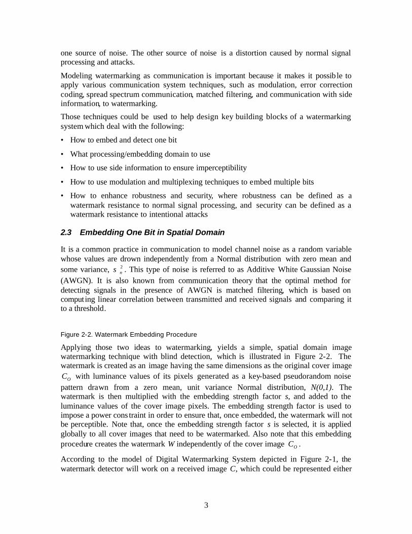
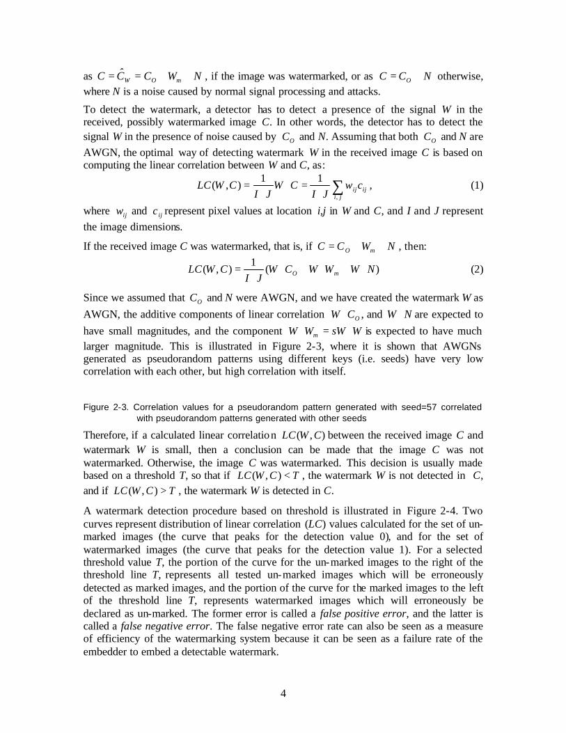
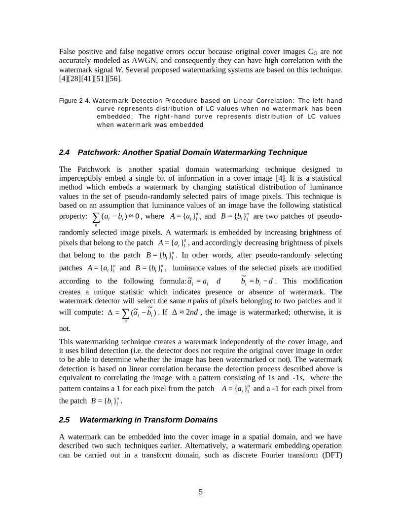


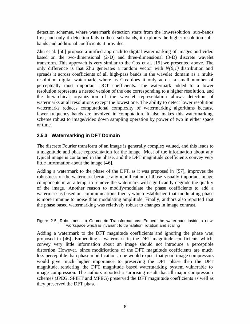


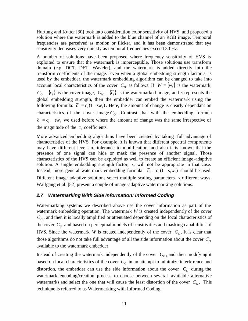
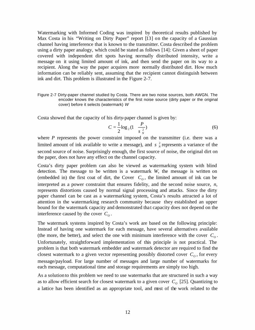
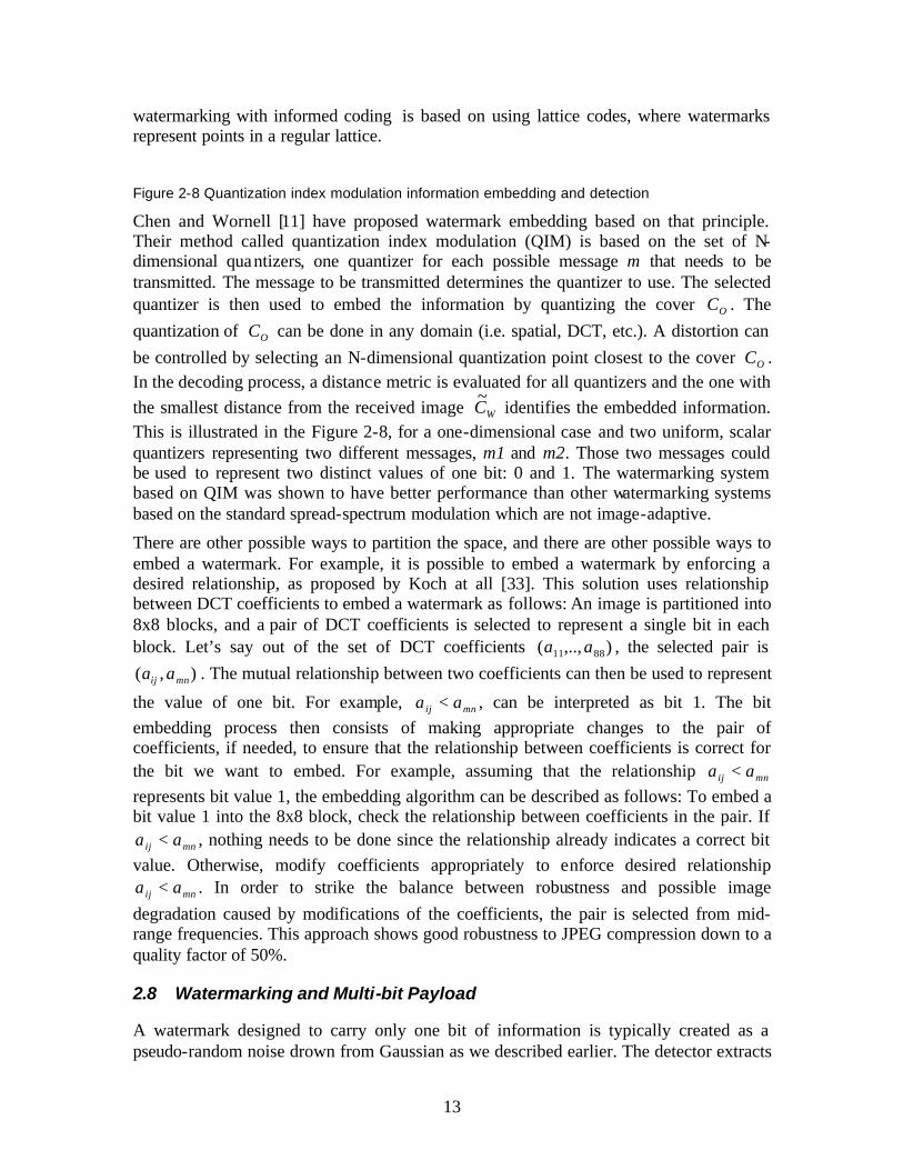


![Borko Jovanovic, MS, PhD Biostatistician [email protected]](https://static.documents.pub/doc/80x56/61fb98b72e268c58cd600e97/borko-jovanovic-ms-phd-biostatistician-emailprotected.jpg)


