SUSPENDED AWNINGS IN COMMERCIAL AREAS STRUCTURAL ASSESSMENT OF RISKS IN MUDGEE SHIRE BILL JORDAN & ASSOCIATES PTY LTD CONSULTING ENGINEER AND HERITAGE CONSULTANT PO Box 141 Newcastle NSW 2300 Ph: (02) 4929 4841 Fax: (02) 4929 7933 Email: [email protected]
Transcript
SUSPENDED AWNINGS IN COMMERCIAL
AREAS STRUCTURAL ASSESSMENT OF RISKS IN
MUDGEE SHIRE
B I L L J O R D A N & A S S O C I A T E S P T Y L T D C O N S U L T I N G E N G I N E E R A N D
Bill Jordan & Associates Suspended awnings in commercial areas June 2003 Mudgee and Gulgong
S U S P E N D E D AW N I N G S I N C O M M E RC I A L A R E A S
STRUCTURAL ASSESSMENT OF RISKS IN MUDGEE SHIRE
INTRODUCTION
BACKGROUND
Mudgee Shire Council, jointly with the NSW Heritage Office, commissioned Bill Jordan & Associates Pty Ltd to undertake a study aimed at conserving suspended awnings in the commercial areas of Mudgee and Gulgong. The Heritage Office advised Mudgee Shire Council of its willingness to share the cost of the study by letter dated 3 April 2003 and Bill Jordan & Associates was formally commissioned by Council by email from Mr Peter Whitehall, on Council’s behalf, on 9 April 2003.
The project was initiated following concerns about the risks of hanging awnings collapsing into the street. One such awning has collapsed in Bathurst in recent years from the impact of falling masonry from a collapsing parapet; it is understood that a pedestrian was killed and others injured. Many of the awnings were originally fitted with support posts at the front edge and were converted to the hanging configuration following concerns in the 1950s about their safety when hit by motor vehicles.
Mudgee Shire Council has asked property owners to have their awnings structurally assessed and certified following the Bathurst incident and, as a result of the advice received from local engineers, it was concluded that most hanging awnings could not be shown to be safe and would either have to be supported by posts or subject to major and unsightly strengthening. Whilst the return of posts to awnings originally so supported can be shown to be beneficial in terms of heritage values, many awnings from the early 20th century onwards were originally designed with hangers and support of these awnings by posts would be detrimental to heritage values: this particularly applies to buildings such as the art deco Regent Theatre which is a building of State significance on the NSW Heritage Register.
In this report the term “awning” is used to refer to all over-footpath shelter structures, although many of those fitted with post support are more correctly termed “verandahs”.
SITE VISIT
Mudgee and Gulgong were visited by the writer on 22 and 23 April 2003 and a number of properties inspected as a preliminary assessment. The buildings were looked at together with Mr Christo Aitken, the Mudgee Heritage Advisor and Mr Peter Whitehall of Mudgee Shire Council. One property was also assessed more thoroughly to allow sample calculations, but the time and resources available did not allow assessment adequate for “certification”.
The opportunity was also taken of discussing the issues with local structural engineer Mr Luke Morris of Barnson Consulting Engineers. Mr Morris advised that the conditions under which the original assessments were briefed and carried out required a great degree of conservatism on the part of the engineer to reduce risk. Also, the assessments were done when the previous edition of AS1170.2, the wind loading code, was in force and that code results in higher wind speeds and hence pressures than the current edition.
This report should not be used for assessments outside Mudgee Shire without permission from the author.
2
Bill Jordan & Associates Suspended awnings in commercial areas June 2003 Mudgee and Gulgong
HERITAGE CONSIDERATIONS
TYPES OF AWNINGS
It is necessary to separate the different types of hanging awnings, both structurally and from the point of view of their heritage significance. In the first instance, awning groups are:
1) awnings supported by posts as originally constructed;
2) awnings which had posts originally, were converted to hanging, and have now been converted back to post support;
3) awnings originally supported by posts and converted to hanging in the mid 20th century;
4) awnings built as hanging awnings (from about World War I onwards) and remaining so;
5) awnings which were originally hanging and which have had posts fitted to reduce the risk of failure;
6) cantilever awnings.
The principal focus of this report is groups 3) to 5). In terms of heritage significance groups 4) and 5) need to be assessed carefully because they have been, or could be, altered to the detriment of their significance. In terms of the Burra Charter, however, at least some awnings in group 3) may deserve retention to reflect the period of history in which they were originally converted.
ASSESSMENT AND CONSERVATION
It is beyond the scope of this report to undertake detailed heritage assessments. However, it is recommended that a simple heritage assessment be made and short heritage impact statement (i.e. no more than a few pages) be prepared if work is proposed in individual cases.
In the first instance, in this regard, a list of individual buildings, groups of buildings or streetscapes could be prepared which would alert Council staff where work was contemplated. This might be undertaken by carrying out a photographic survey followed by a categorization of the awnings into the different types listed above with observation of awning attachment details which would highlight the risk factors.
STRUCTURAL ASSESSMENT
BASIS
RELEVANT STANDARDS
Standards Australia has published codes formerly known as the “loading codes” as the AS 1170 series for many years. From the latest editions issued in 2002 these codes have been entitled “Structural design actions” and have been issued jointly with Standards New Zealand. The following are the current codes relevant to this project:
• AS/NZS 1170.2:2002 – Structural design actions, Part 0: General principles
• AS/NZS 1170.1:2002 – Structural design actions, Part 1: Permanent, imposed and other actions
• AS 1170.4—1993 – Minimum design loads on structures, Part 4: Earthquake loads (The application of this code has been amended by AS/NZS 1170.0:2002)
3
Bill Jordan & Associates Suspended awnings in commercial areas June 2003 Mudgee and Gulgong
Mention is also made in this report of AS 3826—1998, Strengthening buildings for earthquake.
FORMER STANDARDS
Much of the work carried out previously has been done when the following codes were in force:
• AS 1170.1—1989 – SAA Loading Code, Part 1: Dead and live loads and combinations
• AS 1170.2—1989 – SAA Loading Code, Part 2: Wind loads
There is a number of significant differences between the former codes and the current ones. This is to be expected as codes continue to be refined as knowledge improves, replacing conservative assumptions made to cover gaps in knowledge. In the case of awnings there have been some significant changes; wind actions, in particular, are now of lesser magnitude than previously.
Imposed actions (Dead and live loads)
Section 4.7.3 of AS 1170.1—1989, which was introduced with Amendment 1 of 1993, classified the loads on awnings in accordance with whether they were attached to single storey buildings or otherwise; the comparable section in the 2002 code, section 3.5.1 classifies them in accordance with whether they are “accessible from adjacent windows, roofs or balconies” or “accessible only from ground level”.
The refinement in definition makes a difference to the loading applicable to quite a number of awnings in Mudgee, reducing the applicable loading for many; the actual loading values remain the same. It also gives scope for making building changes which impede access and which might be more acceptable for conservation purposes.
Wind actions
There have been significant changes in the assessment of wind loading in the 2002 code. For Mudgee this has resulted in ultimate wind speeds being reduced by 7% and the consequent pressures being reduced by 13% in a generalised case. Further refinement is possible by undertaking specific wind load calculations for a particular building: in most cases shielding of a building by adjacent ones, its location in the terrain and its orientation with respect to prevailing winds will reduce loads some more.
Wind data for both Mudgee and Gulgong have been obtained from the Bureau of Meteorology. However, the data are not sufficient to produce any refinement in the calculations.
Earthquake loads
In the Newcastle earthquake of 1989, many street awnings collapsed and a number of people were killed as a result. In most cases the failure was caused by brickwork collapsing onto the awning which then collapsed under the impact of the extra weight which was far in excess of the load normally considered. Although the awnings which caused the casualties were suspended awnings, similar damage with similar results could have occurred with cantilevered or post-supported awnings. Under AS 1170.4, Mudgee has an earthquake acceleration coefficient of approximately 0.085 compared with Sydney, 0.08 and Newcastle, 0.11. Design earthquake force is proportional to the acceleration coefficient, so the design force in Mudgee is only 23% less than that in Newcastle.
In most cases actual design earthquake forces will be less than the design wind forces, but the vulnerability of elements of the building such as unreinforced masonry parapets needs to be considered.
RISK OF FAILURE
FAILURE TYPES
In structural engineering terms, there are two types of “failure” defined by AS 1170.0:2002:
4
Bill Jordan & Associates Suspended awnings in commercial areas June 2003 Mudgee and Gulgong
Limit states, serviceability defined as “states that correspond to conditions beyond which specified service criteria for a structure or structural element are no longer met”
Limit states, ultimate defined as “states associated with collapse, or with similar forms of structural failure.”
For the purposes of this study, where possible it would be prudent to go further and define failure as the state causing risk to human life and limb. In some instances this may allow judgement to be used to go beyond the bounds set down by the code. If “failure” only results in repairs to damaged structures and there are no safety issues, it could be argued that the compromise is justified to preserve heritage significance.
WIND LOADING
DIRECT AWNING WIND LOADING
Wind loading on an awning can result in both downwards and upwards forces. For most of the awnings concerned the downwards design wind forces in AS 1170.2 are twice the upwards ones.
Downwards design wind forces are considerably less than the design forces for live loading (“imposed actions” in the 2002 code) on the awning, and can be excluded from consideration, even when taken in conjunction with live loads, as design live loads are reduced when considered in combination with wind.
Uplift on the awning has been considered a concern in the past, but with the reduced values in the 2002 code it is considered that it would only be of concern in rare cases
Appendix A sets out calculations for typical awning wind loading.
LOADING ON FACADE
In this writer’s opinion, there is a greater risk in many old buildings from wind loads applied to facades or parapets either directly or via awning hanging supports. Each building needs to be individually assessed, but some generic factors are set out later in this report.
In general there is a risk of failure where awning hangers are attached only to walls with no attempt to transfer the loads into side walls, floors or roof structures. Unfortunately, the fitting of hangers in this fashion was common when awning posts were removed from old buildings in the mid 20th century.
EARTHQUAKE LOADING
Masonry parapets are particularly vulnerable under earthquake loading, as a toppling parapet can result in failure both to the awning and front wall. In the worst cases observed after the Newcastle earthquake, in buildings similar to many in Mudgee and Gulgong, the parapet toppled onto the awning, the hangers of which then pulled down the front wall as well.
Simple guidelines for strengthening and securing parapets and building walls have been developed and published as AS 3826—1998. Using these guidelines or adaptations of them will not only satisfy earthquake requirements but, in most instances, wind loading requirements as well.
5
Bill Jordan & Associates Suspended awnings in commercial areas June 2003 Mudgee and Gulgong
SPECIFIC ASSESSMENTS
AWNING HANGER ATTACHMENTS TO SIDE AND DIVIDING WALLS
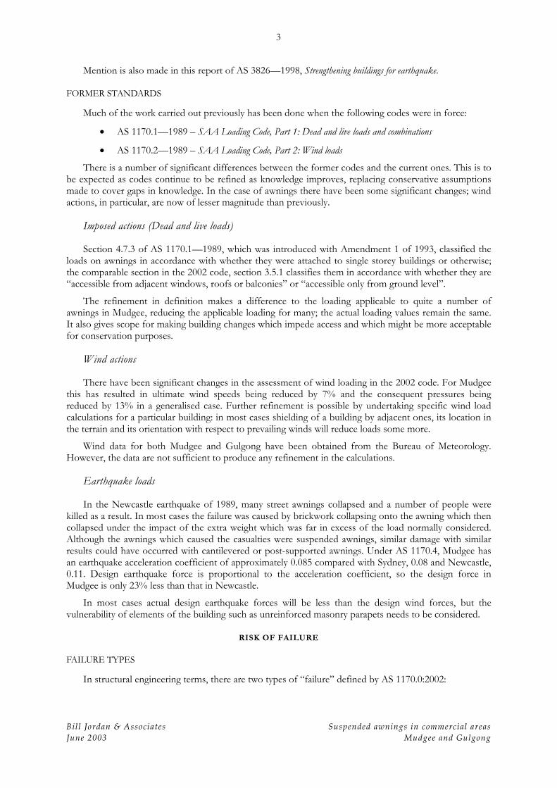
In buildings originally built with hanging awnings, observation indicated that hangers attached at the front of side walls were likely to have the load transferred securely into the brickwork well back along the side wall. For example, in a small shop in Gulgong, appearing to date from before World War II , the embedded steel bar could be seen by way of its surface corrosion, as seen in figure 1.
The attachment of this awning is seen as a pointer to building practice at the time. It should be possible to find similar attachment details and the extent of them in other buildings by close inspection of the applicable bed joint and/or by using a metal detector.
In all instances corrosion has to be taken into account, but in the Mudgee climate it is unlikely that major problems will be found unless there have been other corrosive influences.
ATTACHMENT TO FRONT WALLS
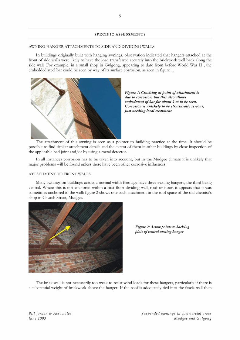
Many awnings on buildings across a normal width frontage have three awning hangers, the third being central. Where this is not anchored within a first floor dividing wall, roof or floor, it appears that it was sometimes anchored in the wall: figure 2 shows one such attachment in the roof space of the old chemist’s shop in Church Street, Mudgee.
The brick wall is not necessarily too weak to resist wind loads for these hangers, particularly if there is a substantial weight of brickwork above the hanger. If the roof is adequately tied into the fascia wall then
Figure 1: Cracking at point of attachment is due to corrosion, but this also allows embedment of bar for about 2 m to be seen. Corrosion is unlikely to be structurally serious, just needing local treatment.
Figure 2: Arrow points to backing plate of central awning hanger
6
Bill Jordan & Associates Suspended awnings in commercial areas June 2003 Mudgee and Gulgong
it is likely that it could also be shown to resist design earthquake loads. Each case needs to be assessed individually.
However, it would be possible to adopt the details given in AS 3826—1998 to make sure that the centre hanger does not rely solely on brickwork for its support. Appendix B gives some suggestions.
APPLIED LOADS
The other design consideration is the ability of the awning to carry occasional loads from people on them. AS 1170.1:2002 sets out a uniformly distributed “imposed action” of 1.0 kPa where the awning is only accessible from ground level and 1.5 kPa where it is accessible from adjacent windows, roofs or balconies. A nominated concentrated action of 1.8 kN will usually be less critical than the distributed action in the cases concerned.
Preliminary calculations have been carried out for the awning of the old chemist’s shop in Church Street Mudgee. These calculations resulted in a preliminary determination of the capacity of the hanging rods and their attachments. Accurate calculations were not possible because the full weight of the awning could not be ascertained without lifting roofing, and the dimensions and details of the hanging rods and their attachments could not be determined from the ground. However, the calculations carried out
Figure 4: Typical hanger attachment from 1920s which does not have the same inherent weakness as that shown in figure 3.
Figure 3: Typical hanger attachment using hook which might need strengthening. This building appears to date from around WWI.
7
Bill Jordan & Associates Suspended awnings in commercial areas June 2003 Mudgee and Gulgong
indicate that most awnings, particularly those where access is not readily available, are likely to conform to requirements providing they have not be weakened by corrosion or physical damage.
For the awning concerned, it was calculated that the centre hanging rod, which takes more than half the load, is stressed to approximately 120 MPa under factored ultimate loads. Even if the rods are of wrought iron, rather than steel, this stress is considered acceptable. Attachments need to be proven for the load: in particular, the hook at the top, wall attachment is likely to be overstressed and a careful measurement and analysis of the hook would be required in individual cases. If the hook is found to be in need of strengthening an unobtrusive bar could be welded across the open part of the hook and give the necessary strength.
The inherent weakness in the hooked attachment seems to have been recognized in later buildings and a more secure yoke and bolt attachment has been used. These still need to be checked, particularly for corrosion, as there are more hidden crevices where rust could start and be hidden.
It is also relevant that many of the hanging awnings have had 80 or more years of service without signs of structural distress. In this writer’s opinion, the approach to assessing the awnings should be to firstly assess why they have survived so long before trying to apply current codes simplistically. With this approach the inherent strengths of the structures may become apparent. However, all elements of a structure which might influence the awning need to be taken into account. As noted above, the principal cause of failure of awnings during the Newcastle earthquake was the collapse onto them of unsecured parapets.
OTHER COMMENTS
REGENT THEATRE, MUDGEE
The Regent Theatre is a 1930s Art Deco building which is on the State Heritage Register. It is our opinion that this building’s awning can be shown to meet all requirements:
• the awning hanging rods are secured at the top by full rings, not hooks;
Figure 5
8
Bill Jordan & Associates Suspended awnings in commercial areas June 2003 Mudgee and Gulgong
• the weight of brickwork above the hanging rods should be sufficient to secure them even if they are only wall mounted;
• there are no signs of structural distress;
• the awning contains many steel members and is likely to have sufficient weight to resist uplift;
• adequacy of attachments of the roof and floors to the front wall needs to be checked and supplemented if necessary;
• the stability of the parapet needs to be investigated;
• corrosion needs to be checked.
SHOP IN HERBERT STREET, GULGONG
The shop in Gulgong shown in figure 6 appears to date from the 1920s with the hanging awning as original construction. Unsympathetic support posts have been fitted.
Observation indicates that the front wall above the awning has bowed out and this could be unstable
with or without the support posts fitted to the awning. It is suggested that the front wall be strengthened by installation of a suitable internal structure and that roof and parapet attachment details similar to those in Appendix B be fitted. It is likely that the posts can then be removed, returning the awning to its original configuration.
CIVIC THEATRE, MUDGEE
The Civic Theatre in Mudgee is another Art Deco style building which, although as not as prominent as the Regent Theatre, is of a type which is becoming rarer in NSW. It, too, has had unsympathetic support posts fitted to the awning.
Figure 6
9
Bill Jordan & Associates Suspended awnings in commercial areas June 2003 Mudgee and Gulgong
It is our opinion that a proper engineering assessment, possibly leading to installation of some hidden strengthening or securing of the front wall, would allow these unsightly posts to be removed.
HAZARDOUS PARAPETS
It is understood that there is a proposal to reconstruct a posted awning on the building shown in Figure 8, in Market Street, Mudgee. This building has a parapet which is particularly vulnerable to damage in an earthquake or extreme winds. There is a risk to pedestrians even for a post supported awning because of the large mass of masonry which could fall. It is recommended that suitable securing and/or strengthening be undertaken on this parapet and that it be done sympathetically to the historic fabric.
Figure 7
Figure 8
10
Bill Jordan & Associates Suspended awnings in commercial areas June 2003 Mudgee and Gulgong
CONCLUSION AND RECOMMENDATIONS
Suspended awnings in the commercial areas of Mudgee and Gulgong form part of the historic fabric of the towns and many have heritage significance in that configuration and should be conserved.
Assessment indicates that most original hanging awnings can fulfil strength requirements providing adequate resources are available to carry out the engineering required and some strengthening is undertaken in accordance with standard details.
It is recommended that heritage assessments be commissioned to identify significant hanging awnings and that resources be sought to allow the conservation of those of high significance which make a contribution to the community.
J.W. Jordan FIEAust CPEng NPER Structural Reg. No. 161488 June 2003
APPENDICES
A. Sample wind loading calculations
B. AS 3826—1998 details with suggestions
APPENDIX A
WIND LOAD CALCULATIONS FOR AWNING UPLIFT
Section, figure, equation, table and appendix references are to AS 1170.2:2002
WIND SPEED CALCULATION
Risk factors
Under Building Code of Australia, all building awnings can be considered as having Importance Level 2 (considered on its own, the Regent Theatre awning would have this value, although building as a whole would be Level 3)
Consequently, Annual Probability of Exceedance = 1:500
(There may be some argument for heritage buildings of great significance being analysed using a higher figure, say 1:1000, but that needs to be decided elsewhere.)
Location
Mudgee is located near the border of regions A1 & A3 in Figure 3.1.
(Table 3.1): V500 = 45 m/s (= VR) direction not specified in generic case, hence directional modifier, Md = 1.0 (Table 3.2);
(This could be as low as 0.80 for specific buildings).
Terrain & site exposure
Terrain category is a measure of terrain roughness and shielding by other buildings. Section 4.2.1 places the town centre in Terrain category 3 (TC3) but reference to the AS 1170.2:2002 Commentary indicates that a slightly rougher terrain can be assumed for centres of small towns. For buildings up to 10 m high, which covers most of the towns concerned, the applicable Terrain/Height multiplier is 0.81. This may need to be modified at the edge of the developed area in accordance with Section 4.2.3.
So, Mz,cat = 0.81
Shielding
Shielding of buildings from wind by adjacent buildings is calculated in accordance with Section 4.3. Assuming 60 m (2 chain) width roads and building heights of 6 m, (conservative) the shielding multiplier can be as low as = 0.75. However, in the conservative generic case adopt Ms = 1.0
Topography
The topographic multiplier accounts for increased wind speeds on hills and escarpments. No such effects are likely in most of Mudgee and Gulgong, so adopt Mt = 1.0.
Design wind speed
Equation 2.2: Vsit, = VRMd(Mz,catMsMt)
So, Vsit, = 45 x 1.0 x 0.81 x 1.0 x 1.0 = 36.5 m/s (ultimate) This is likely to be a maximum and consideration of some of the other factors noted above would
reduce it for individual buildings.
2
Bill Jordan & Associates Suspended awnings in commercial areas June 2003 Mudgee and Gulgong
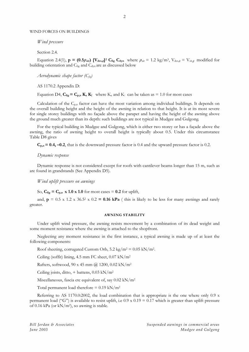
WIND FORCES ON BUILDINGS
Wind pressure
Section 2.4.
Equation 2.4(1), p = (0.5 air) [Vdes, ]2 Cfig Cdyn where air = 1.2 kg/m3, Vdes, = Vsit, modified for building orientation and Cfig and Cdyn are as discussed below
Aerodynamic shape factor (Cfig)
AS 1170.2 Appendix D:
Equation D4, Cfig = Cp,n Ka Kl where Ka and Kl can be taken as = 1.0 for most cases
Calculation of the Cp,n factor can have the most variation among individual buildings. It depends on the overall building height and the height of the awning in relation to that height. It is at its most severe for single storey buildings with no façade above the parapet and having the height of the awning above the ground much greater than its depth: such buildings are not typical in Mudgee and Gulgong.
For the typical building in Mudgee and Gulgong, which is either two storey or has a façade above the awning, the ratio of awning height to overall height is typically about 0.5. Under this circumstance Table D8 gives
Cp,n = 0.4, –0.2, that is the downward pressure factor is 0.4 and the upward pressure factor is 0.2.
Dynamic response
Dynamic response is not considered except for roofs with cantilever beams longer than 15 m, such as are found in grandstands (See Appendix D5).
Wind uplift pressure on awnings
So, Cfig = Cp,n x 1.0 x 1.0 for most cases = 0.2 for uplift,
and, p = 0.5 x 1.2 x 36.52 x 0.2 = 0.16 kPa ( this is likely to be less for many awnings and rarely greater.
AWNING STABILITY
Under uplift wind pressure, the awning resists movement by a combination of its dead weight and some moment resistance where the awning is attached to the shopfront.
Neglecting any moment resistance in the first instance, a typical awning is made up of at least the following components:
Ceiling (soffit) lining, 4.5 mm FC sheet, 0.07 kN/m2
Rafters, softwood, 90 x 45 mm @ 1200, 0.02 kN/m2
Ceiling joists, ditto, + battens, 0.03 kN/m2
Miscellaneous, fascia etc equivalent of, say 0.02 kN/m2
Total permanent load therefore = 0.19 kN/m2
Referring to AS 1170.0:2002, the load combination that is appropriate is the one where only 0.9 x permanent load (“G”) is available to resist uplift, i.e 0.9 x 0.19 = 0.17 which is greater than uplift pressure of 0.16 kPa (or kN/m2), so awning is stable.
3
Bill Jordan & Associates Suspended awnings in commercial areas June 2003 Mudgee and Gulgong
There are secondary restraints, such as the moment resistance at the edge of the shopfront, and most awnings include steel components which would make them heavier and more resistant to uplift.
It is concluded, therefore, that typical awnings in Mudgee and Gulgong are resistant to wind uplift, but each needs separate assessment to ensure that this is so.
APPENDIX B
DETAILS FROM AS 3826—1998
These details should not be applied without structural engineering advice.
Figure B1: Excerpts from details in AS 3826—1998 suitable for fascia wall stabilization. Modifications shown required to secure awning hangers which should be attached positively to steel or timber stud as required by engineering analysis.
2
Bill Jordan & Associates Suspended awnings in commercial areas June 2003 Mudgee and Gulgong
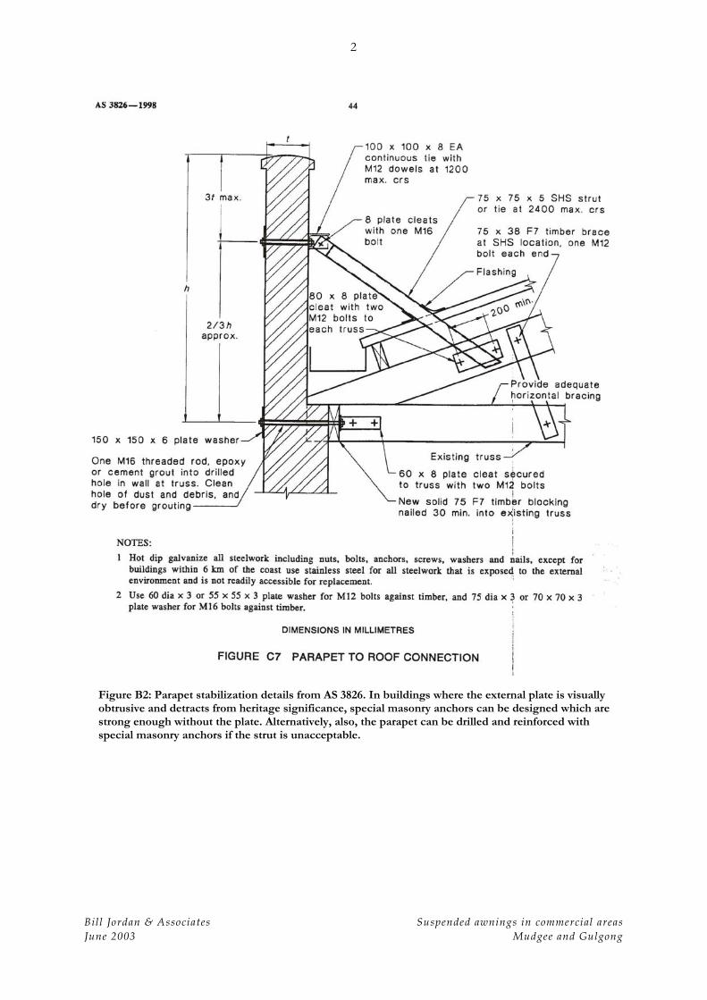
Figure B2: Parapet stabilization details from AS 3826. In buildings where the external plate is visually obtrusive and detracts from heritage significance, special masonry anchors can be designed which are strong enough without the plate. Alternatively, also, the parapet can be drilled and reinforced with special masonry anchors if the strut is unacceptable.