24
116 SUSPENSION A journey of a thousand miles begins with a single step. Confucius
116
SUSPENSIONA journey of a thousand miles begins with a single step.
Confucius
117
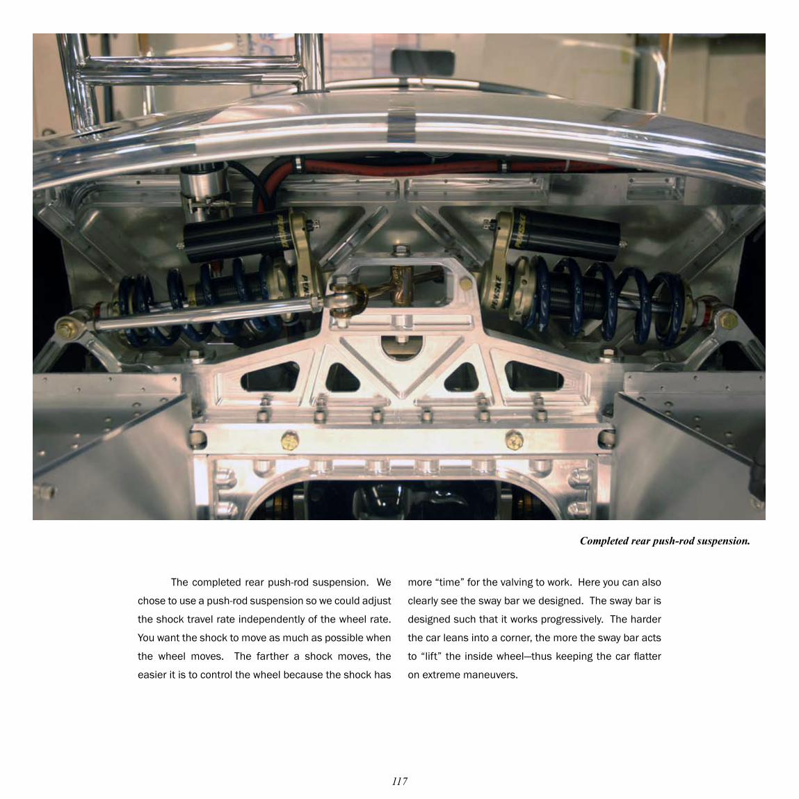
The completed rear push-rod suspension. We
chose to use a push-rod suspension so we could adjust
the shock travel rate independently of the wheel rate.
You want the shock to move as much as possible when
the wheel moves. The farther a shock moves, the
easier it is to control the wheel because the shock has
Completed rear push-rod suspension.
more “time” for the valving to work. Here you can also
clearly see the sway bar we designed. The sway bar is
designed such that it works progressively. The harder
the car leans into a corner, the more the sway bar acts
to “lift” the inside wheel—thus keeping the car flatter
on extreme maneuvers.
118
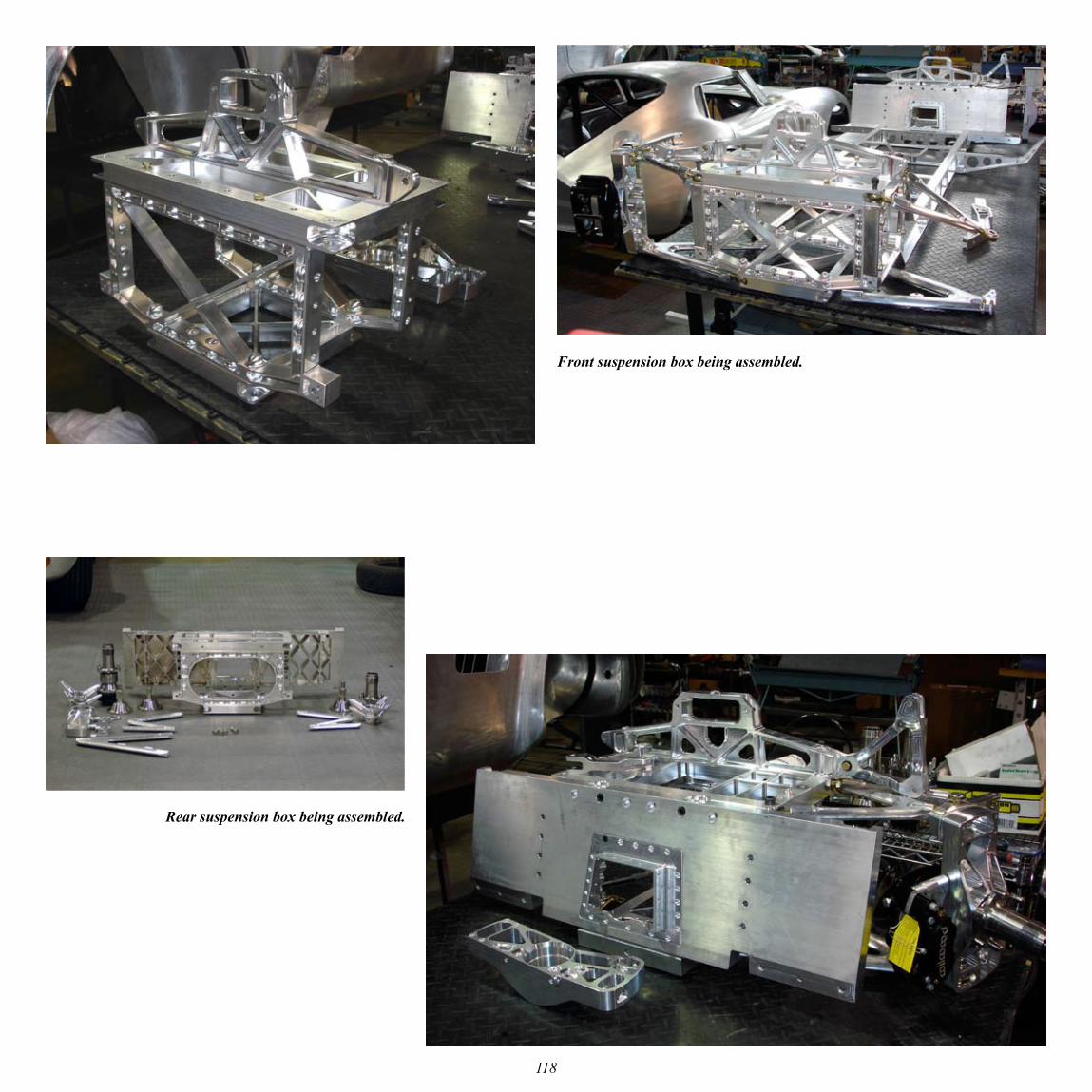
Front suspension box being assembled.
Rear suspension box being assembled.
119
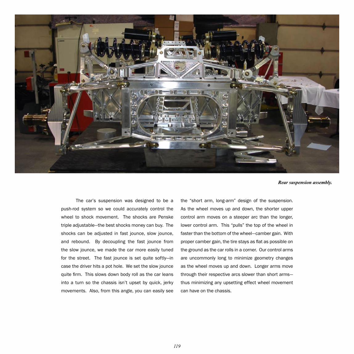
The car’s suspension was designed to be a
push-rod system so we could accurately control the
wheel to shock movement. The shocks are Penske
triple adjustable—the best shocks money can buy. The
shocks can be adjusted in fast jounce, slow jounce,
and rebound. By decoupling the fast jounce from
the slow jounce, we made the car more easily tuned
for the street. The fast jounce is set quite softly—in
case the driver hits a pot hole. We set the slow jounce
quite firm. This slows down body roll as the car leans
into a turn so the chassis isn’t upset by quick, jerky
movements. Also, from this angle, you can easily see
Rear suspension assembly.
the “short arm, long-arm” design of the suspension.
As the wheel moves up and down, the shorter upper
control arm moves on a steeper arc than the longer,
lower control arm. This “pulls” the top of the wheel in
faster than the bottom of the wheel—camber gain. With
proper camber gain, the tire stays as flat as possible on
the ground as the car rolls in a corner. Our control arms
are uncommonly long to minimize geometry changes
as the wheel moves up and down. Longer arms move
through their respective arcs slower than short arms—
thus minimizing any upsetting effect wheel movement
can have on the chassis.
120
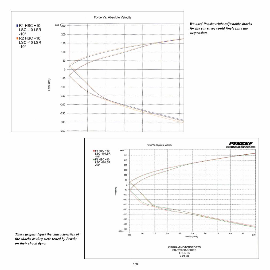
We used Penske triple-adjustable shocks for the car so we could finely tune the suspension.
These graphs depict the characteristics of the shocks as they were tested by Penske on their shock dyno.
121
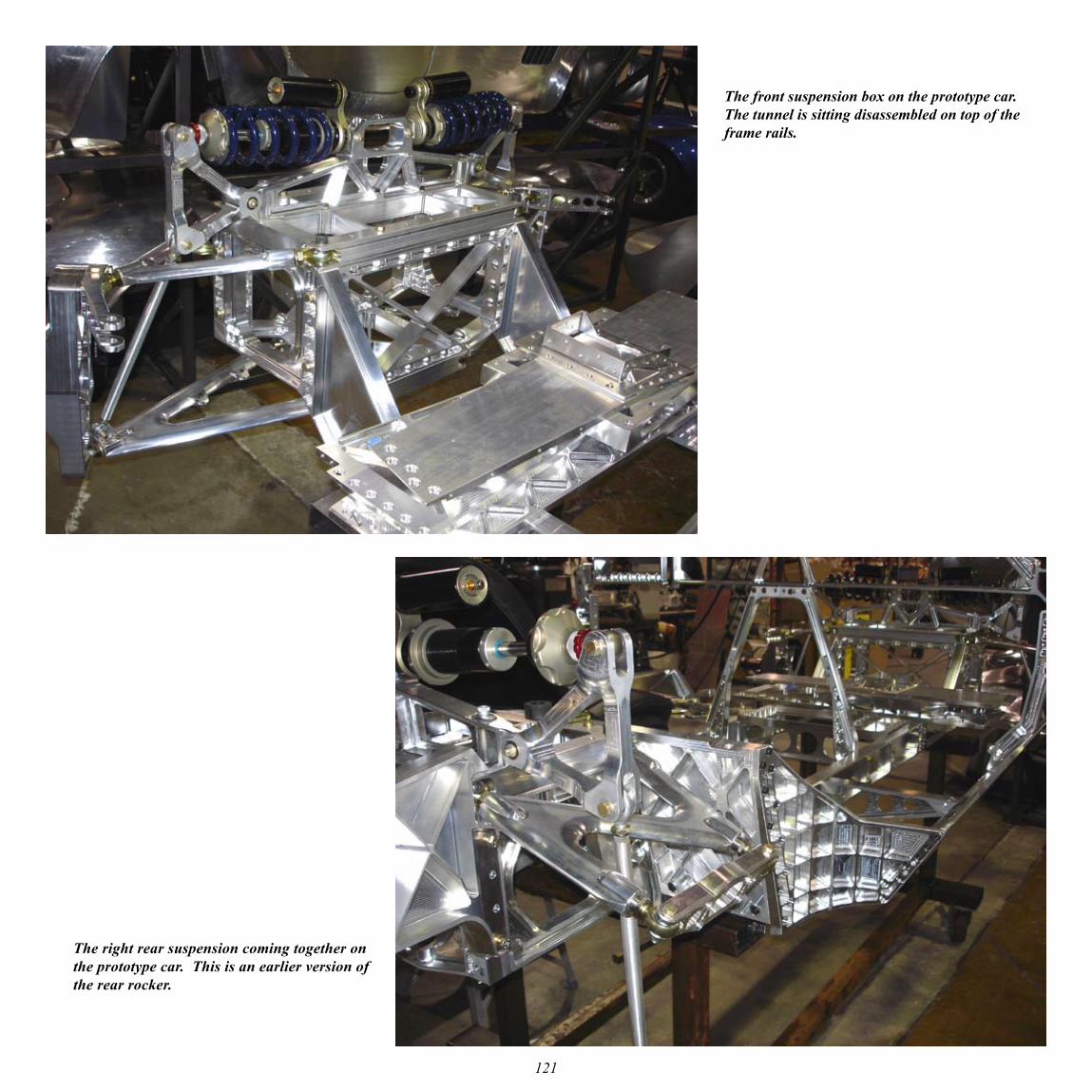
The front suspension box on the prototype car. The tunnel is sitting disassembled on top of the frame rails.
The right rear suspension coming together on the prototype car. This is an earlier version of the rear rocker.
122
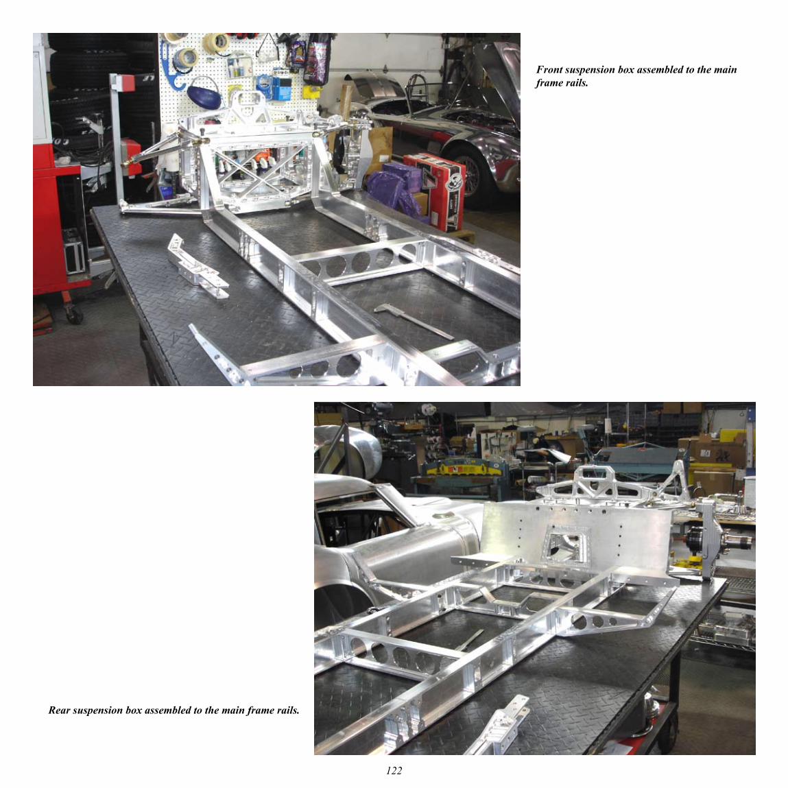
Front suspension box assembled to the main frame rails.
Rear suspension box assembled to the main frame rails.
123
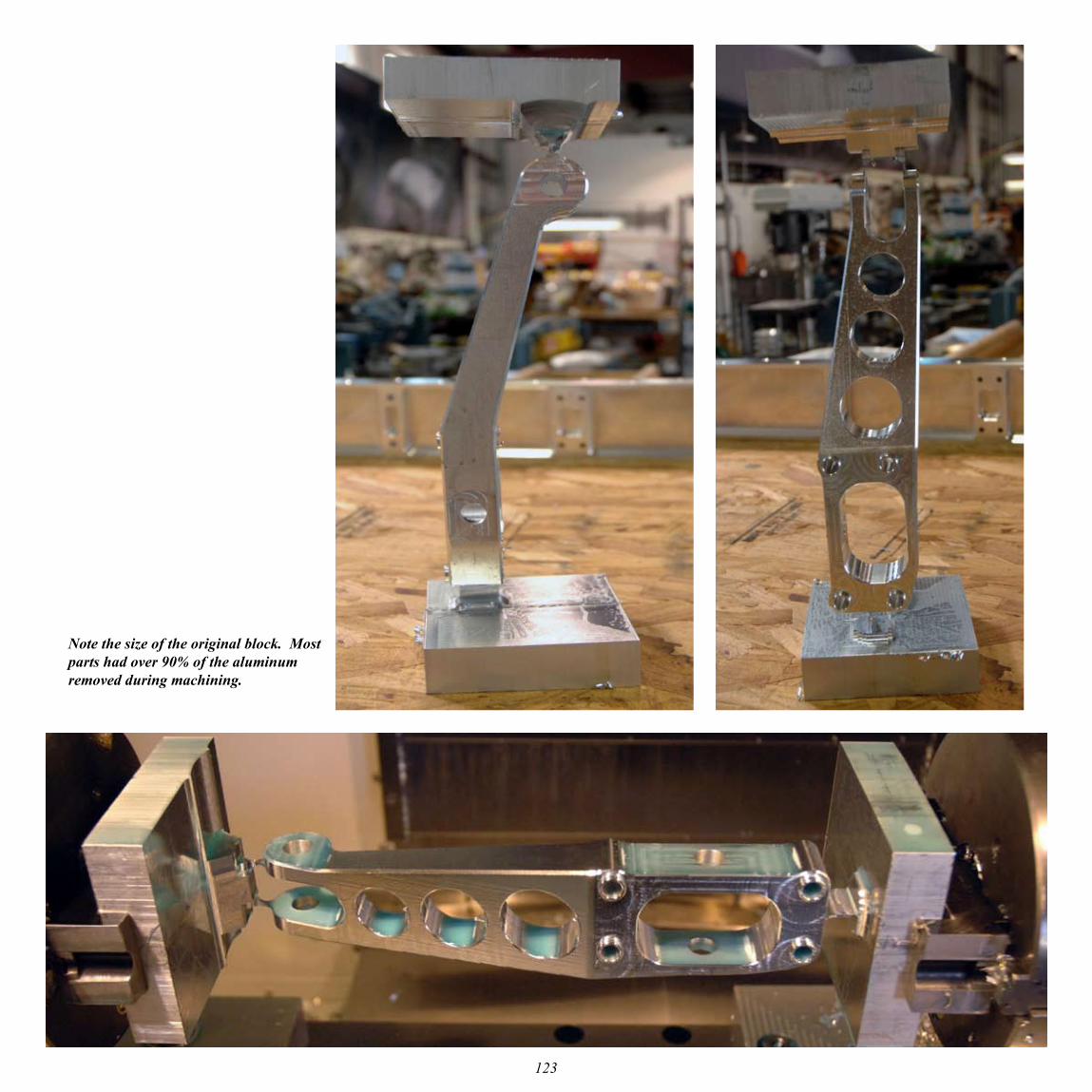
Note the size of the original block. Most parts had over 90% of the aluminum removed during machining.
124
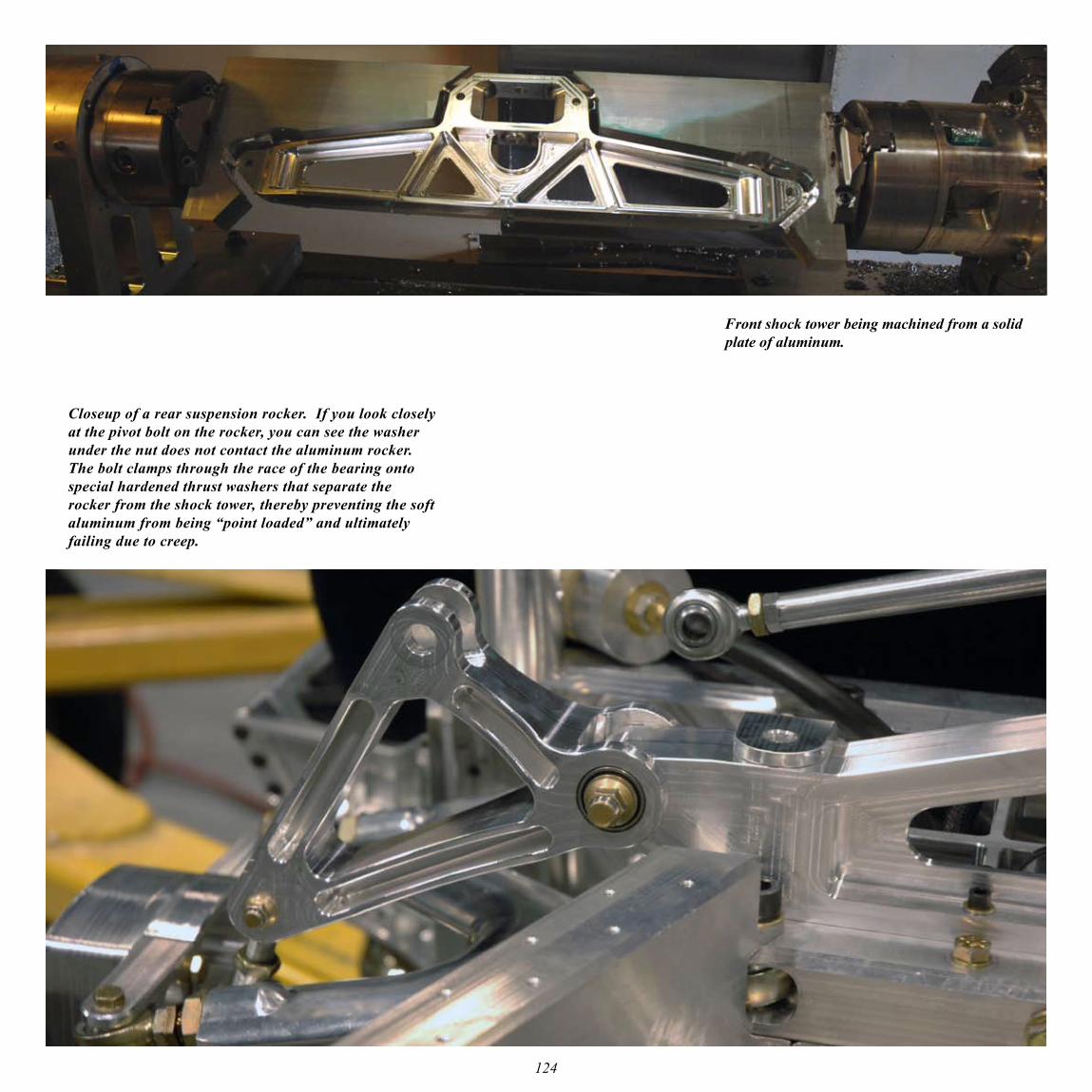
Front shock tower being machined from a solid plate of aluminum.
Closeup of a rear suspension rocker. If you look closely at the pivot bolt on the rocker, you can see the washer under the nut does not contact the aluminum rocker. The bolt clamps through the race of the bearing onto special hardened thrust washers that separate the rocker from the shock tower, thereby preventing the soft aluminum from being “point loaded” and ultimately failing due to creep.
125
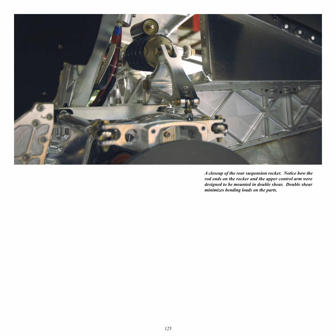
A closeup of the rear suspension rocker. Notice how the rod ends on the rocker and the upper control arm were designed to be mounted in double shear. Double shear minimizes bending loads on the parts.
126
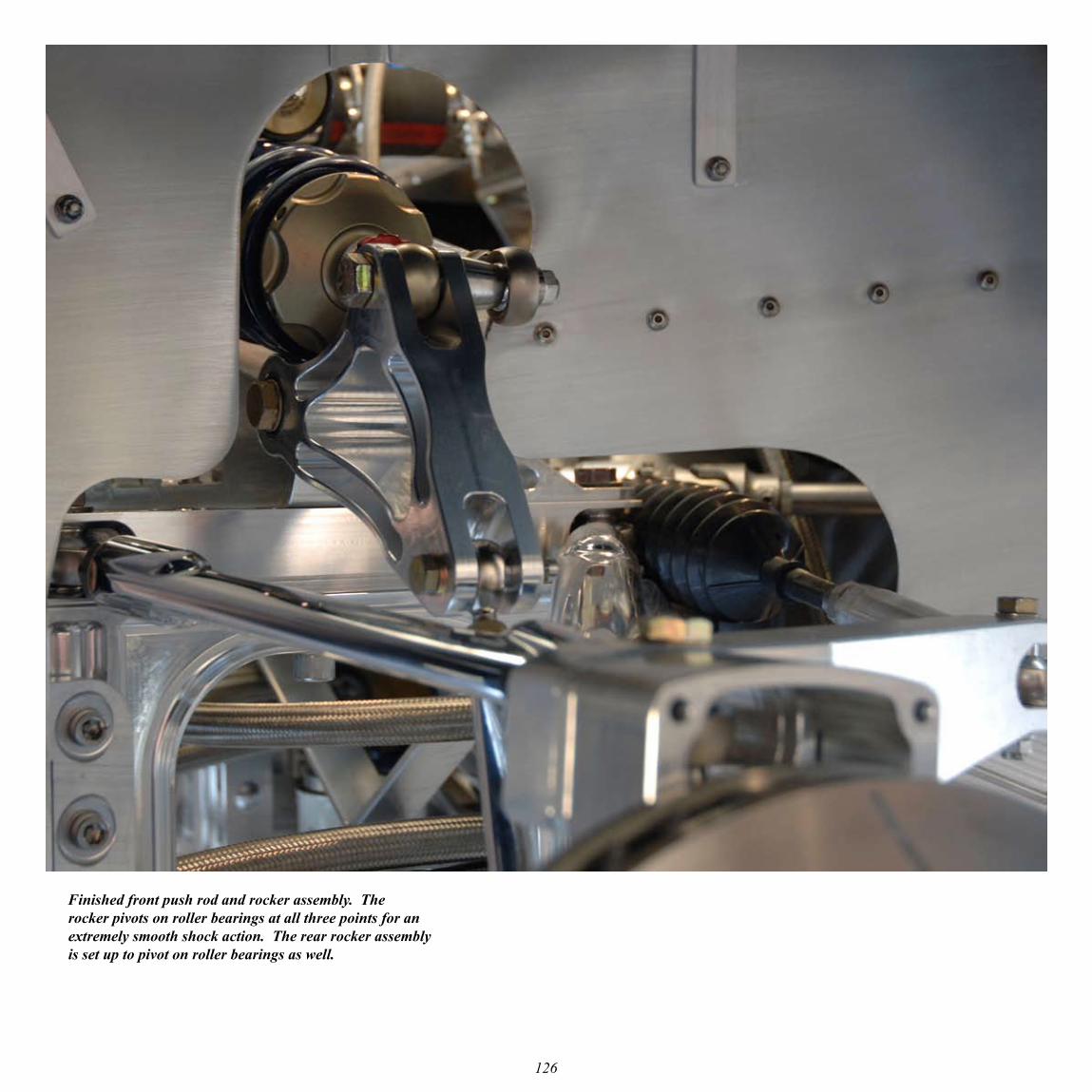
Finished front push rod and rocker assembly. The rocker pivots on roller bearings at all three points for an extremely smooth shock action. The rear rocker assembly is set up to pivot on roller bearings as well.
127
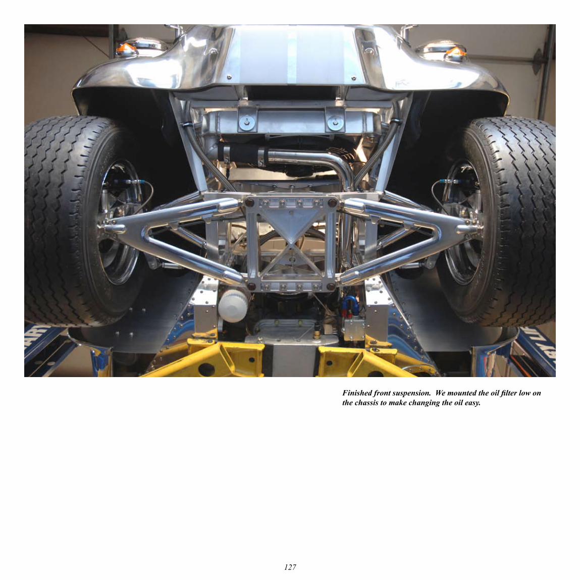
Finished front suspension. We mounted the oil filter low on the chassis to make changing the oil easy.

128
The operation of the sway bar is easy to see in this picture. The design of the sway bar is inherently progressive. The sway bar was machined from a 2-inch bar of 17-4 PH and then precipitation hardened in our shop.
129
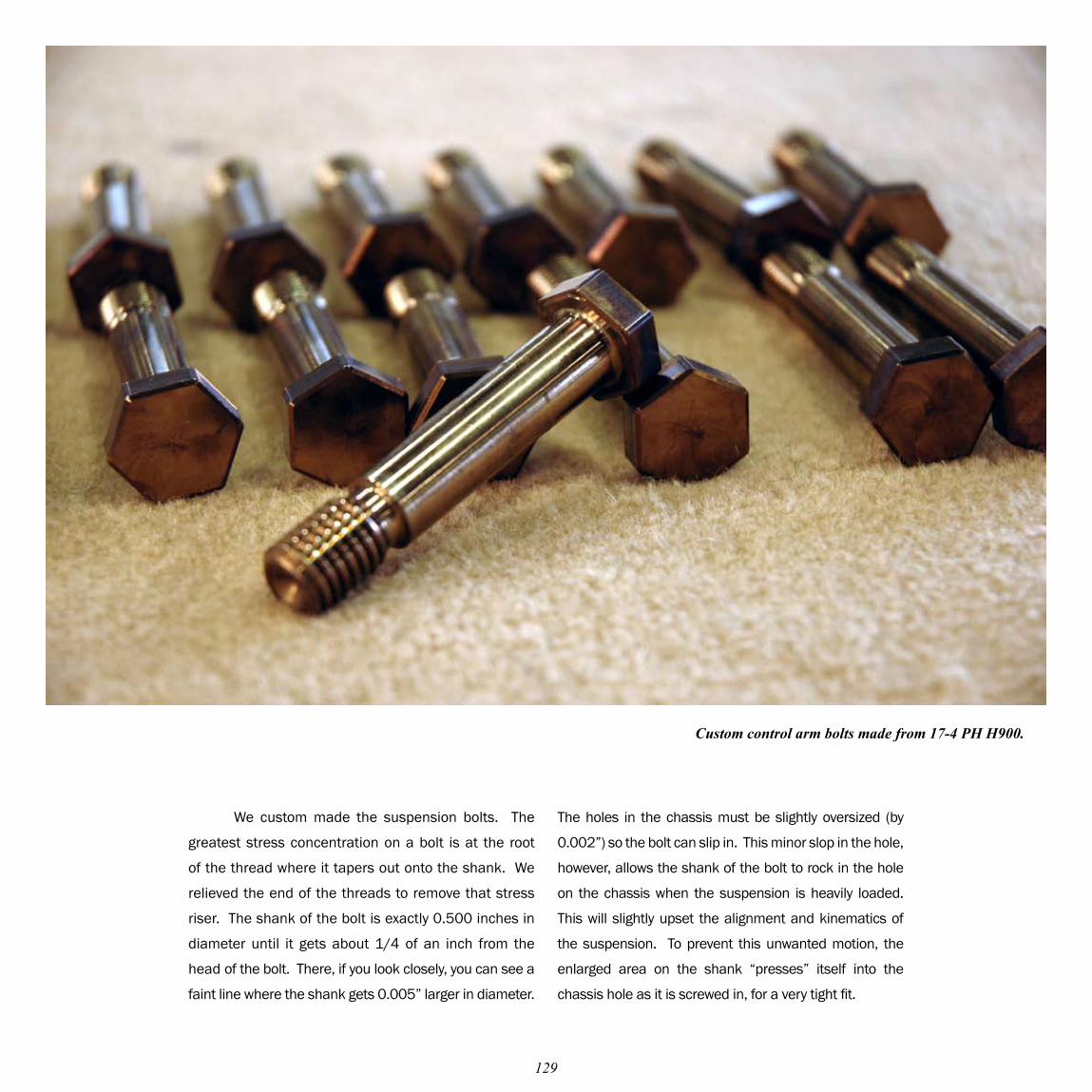
We custom made the suspension bolts. The
greatest stress concentration on a bolt is at the root
of the thread where it tapers out onto the shank. We
relieved the end of the threads to remove that stress
riser. The shank of the bolt is exactly 0.500 inches in
diameter until it gets about 1/4 of an inch from the
head of the bolt. There, if you look closely, you can see a
faint line where the shank gets 0.005” larger in diameter.
Custom control arm bolts made from 17-4 PH H900.
The holes in the chassis must be slightly oversized (by
0.002”) so the bolt can slip in. This minor slop in the hole,
however, allows the shank of the bolt to rock in the hole
on the chassis when the suspension is heavily loaded.
This will slightly upset the alignment and kinematics of
the suspension. To prevent this unwanted motion, the
enlarged area on the shank “presses” itself into the
chassis hole as it is screwed in, for a very tight fit.
130
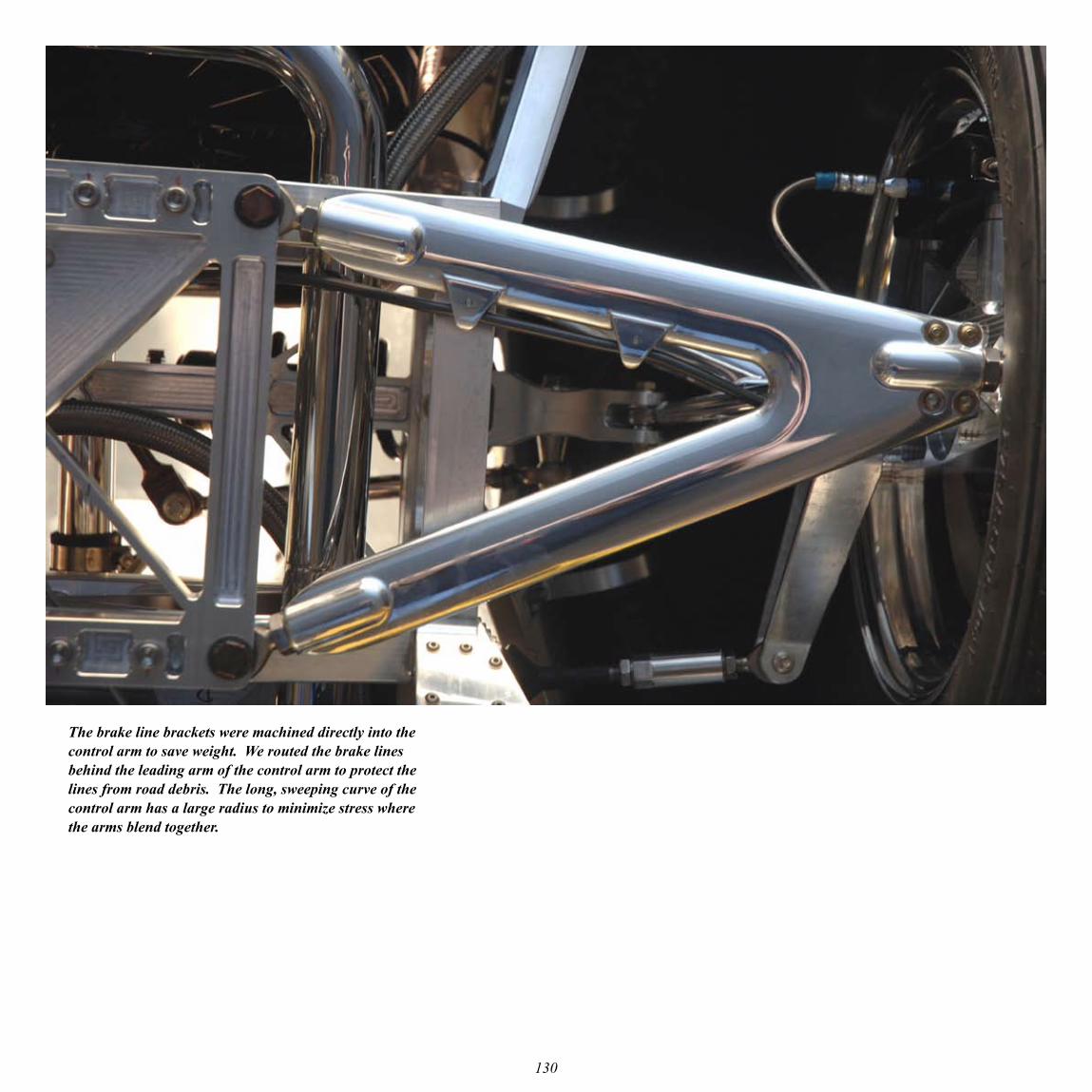
The brake line brackets were machined directly into the control arm to save weight. We routed the brake lines behind the leading arm of the control arm to protect the lines from road debris. The long, sweeping curve of the control arm has a large radius to minimize stress where the arms blend together.
131
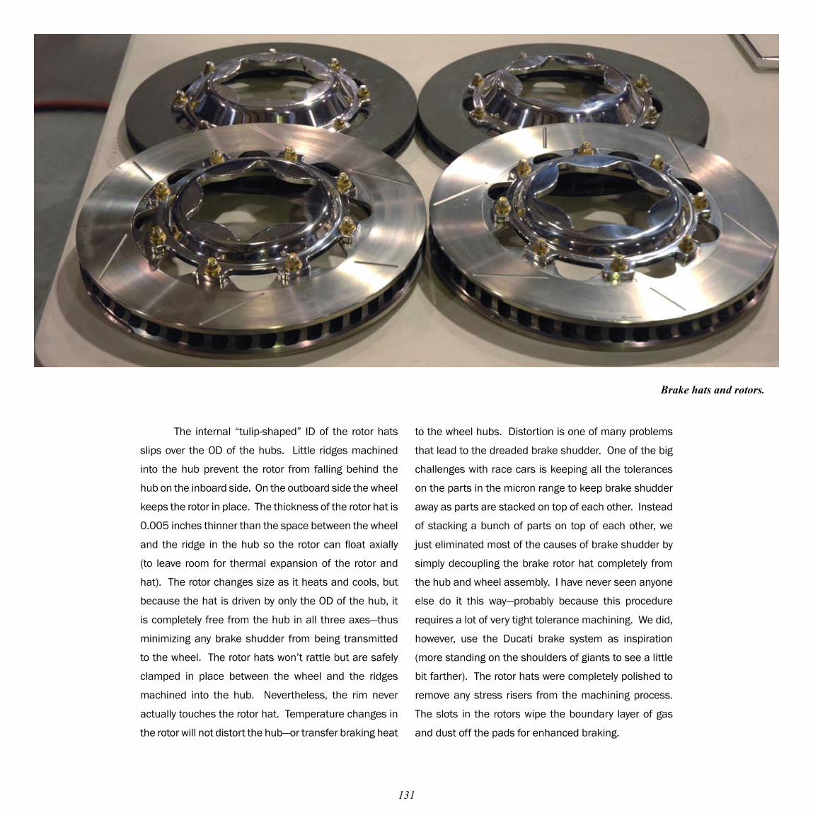
The internal “tulip-shaped” ID of the rotor hats
slips over the OD of the hubs. Little ridges machined
into the hub prevent the rotor from falling behind the
hub on the inboard side. On the outboard side the wheel
keeps the rotor in place. The thickness of the rotor hat is
0.005 inches thinner than the space between the wheel
and the ridge in the hub so the rotor can float axially
(to leave room for thermal expansion of the rotor and
hat). The rotor changes size as it heats and cools, but
because the hat is driven by only the OD of the hub, it
is completely free from the hub in all three axes—thus
minimizing any brake shudder from being transmitted
to the wheel. The rotor hats won’t rattle but are safely
clamped in place between the wheel and the ridges
machined into the hub. Nevertheless, the rim never
actually touches the rotor hat. Temperature changes in
the rotor will not distort the hub—or transfer braking heat
Brake hats and rotors.
to the wheel hubs. Distortion is one of many problems
that lead to the dreaded brake shudder. One of the big
challenges with race cars is keeping all the tolerances
on the parts in the micron range to keep brake shudder
away as parts are stacked on top of each other. Instead
of stacking a bunch of parts on top of each other, we
just eliminated most of the causes of brake shudder by
simply decoupling the brake rotor hat completely from
the hub and wheel assembly. I have never seen anyone
else do it this way—probably because this procedure
requires a lot of very tight tolerance machining. We did,
however, use the Ducati brake system as inspiration
(more standing on the shoulders of giants to see a little
bit farther). The rotor hats were completely polished to
remove any stress risers from the machining process.
The slots in the rotors wipe the boundary layer of gas
and dust off the pads for enhanced braking.
132
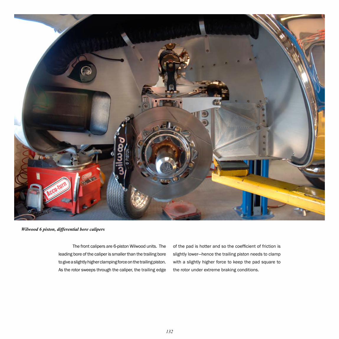
The front calipers are 6-piston Wilwood units. The
leading bore of the caliper is smaller than the trailing bore
to give a slightly higher clamping force on the trailing piston.
As the rotor sweeps through the caliper, the trailing edge
Wilwood 6 piston, differential bore calipers
of the pad is hotter and so the coefficient of friction is
slightly lower—hence the trailing piston needs to clamp
with a slightly higher force to keep the pad square to
the rotor under extreme braking conditions.
133
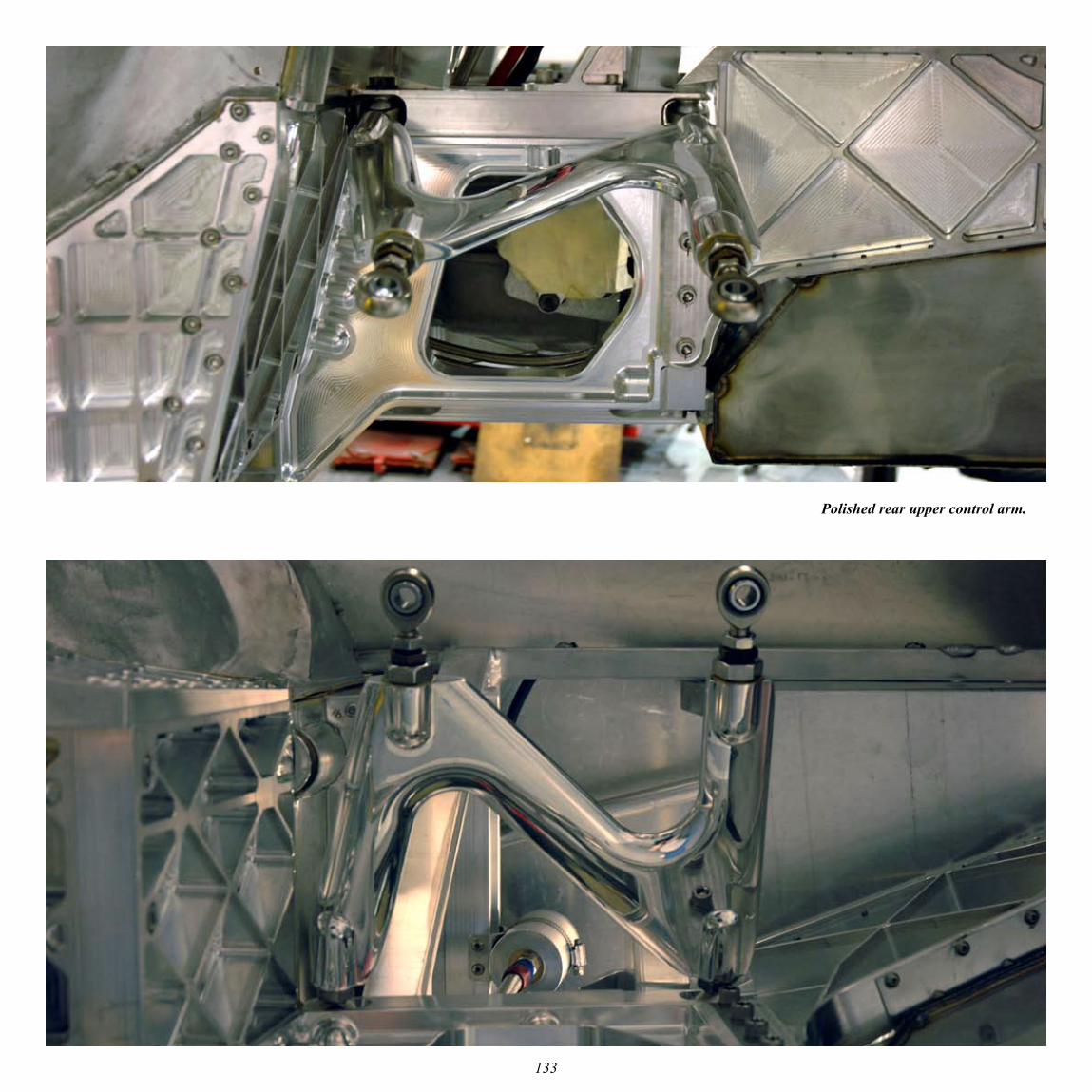
Polished rear upper control arm.
134
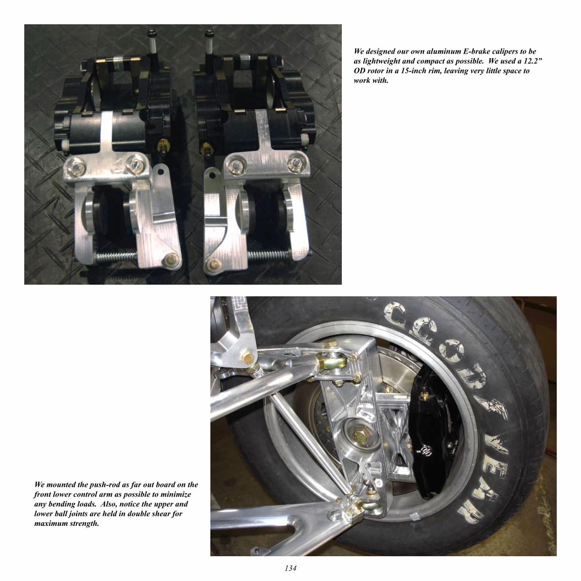
We mounted the push-rod as far out board on the front lower control arm as possible to minimize any bending loads. Also, notice the upper and lower ball joints are held in double shear for maximum strength.
We designed our own aluminum E-brake calipers to be as lightweight and compact as possible. We used a 12.2” OD rotor in a 15-inch rim, leaving very little space to work with.
135
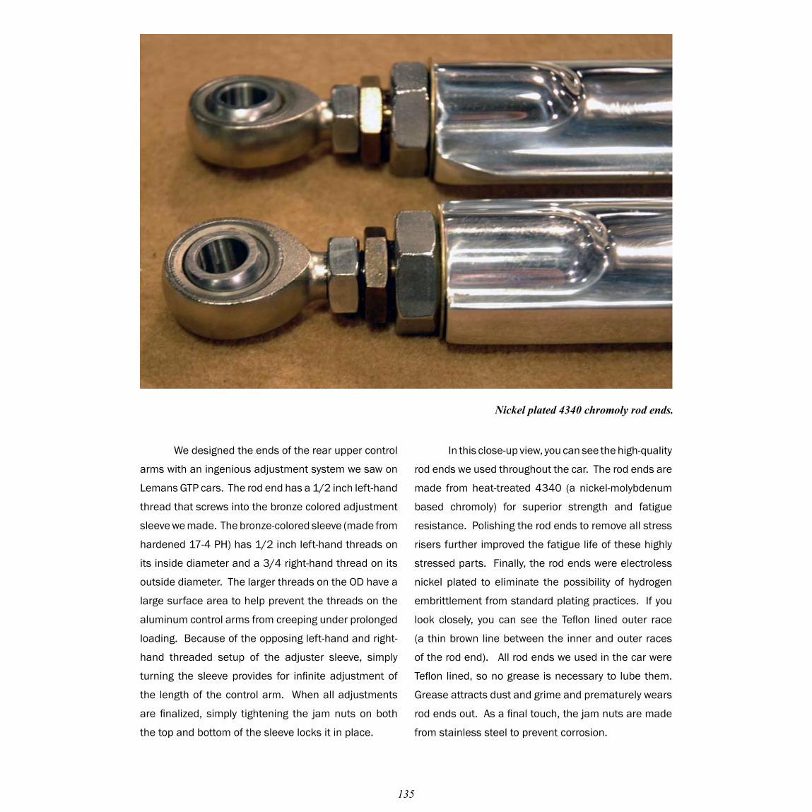
We designed the ends of the rear upper control
arms with an ingenious adjustment system we saw on
Lemans GTP cars. The rod end has a 1/2 inch left-hand
thread that screws into the bronze colored adjustment
sleeve we made. The bronze-colored sleeve (made from
hardened 17-4 PH) has 1/2 inch left-hand threads on
its inside diameter and a 3/4 right-hand thread on its
outside diameter. The larger threads on the OD have a
large surface area to help prevent the threads on the
aluminum control arms from creeping under prolonged
loading. Because of the opposing left-hand and right-
hand threaded setup of the adjuster sleeve, simply
turning the sleeve provides for infinite adjustment of
the length of the control arm. When all adjustments
are finalized, simply tightening the jam nuts on both
the top and bottom of the sleeve locks it in place.
Nickel plated 4340 chromoly rod ends.
In this close-up view, you can see the high-quality
rod ends we used throughout the car. The rod ends are
made from heat-treated 4340 (a nickel-molybdenum
based chromoly) for superior strength and fatigue
resistance. Polishing the rod ends to remove all stress
risers further improved the fatigue life of these highly
stressed parts. Finally, the rod ends were electroless
nickel plated to eliminate the possibility of hydrogen
embrittlement from standard plating practices. If you
look closely, you can see the Teflon lined outer race
(a thin brown line between the inner and outer races
of the rod end). All rod ends we used in the car were
Teflon lined, so no grease is necessary to lube them.
Grease attracts dust and grime and prematurely wears
rod ends out. As a final touch, the jam nuts are made
from stainless steel to prevent corrosion.
136
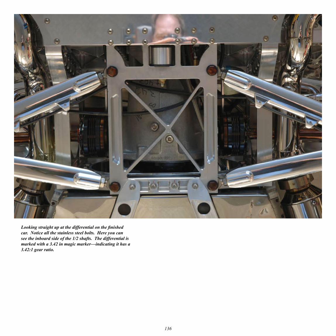
Looking straight up at the differential on the finished car. Notice all the stainless steel bolts. Here you can see the inboard side of the 1/2 shafts. The differential is marked with a 3.42 in magic marker—indicating it has a 3.42:1 gear ratio.
137
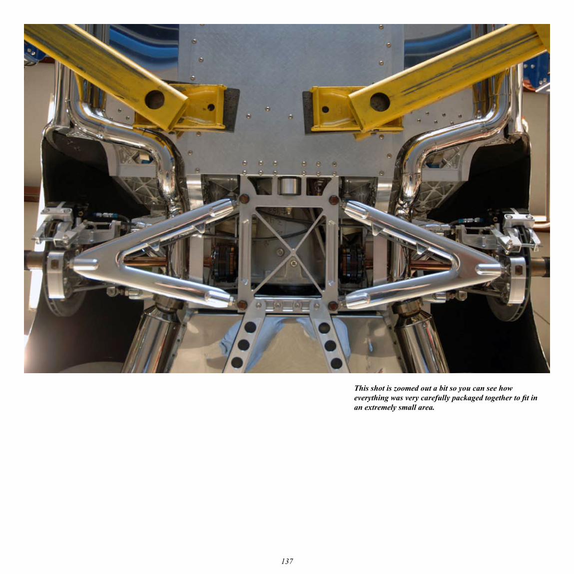
This shot is zoomed out a bit so you can see how everything was very carefully packaged together to fit in an extremely small area.
138
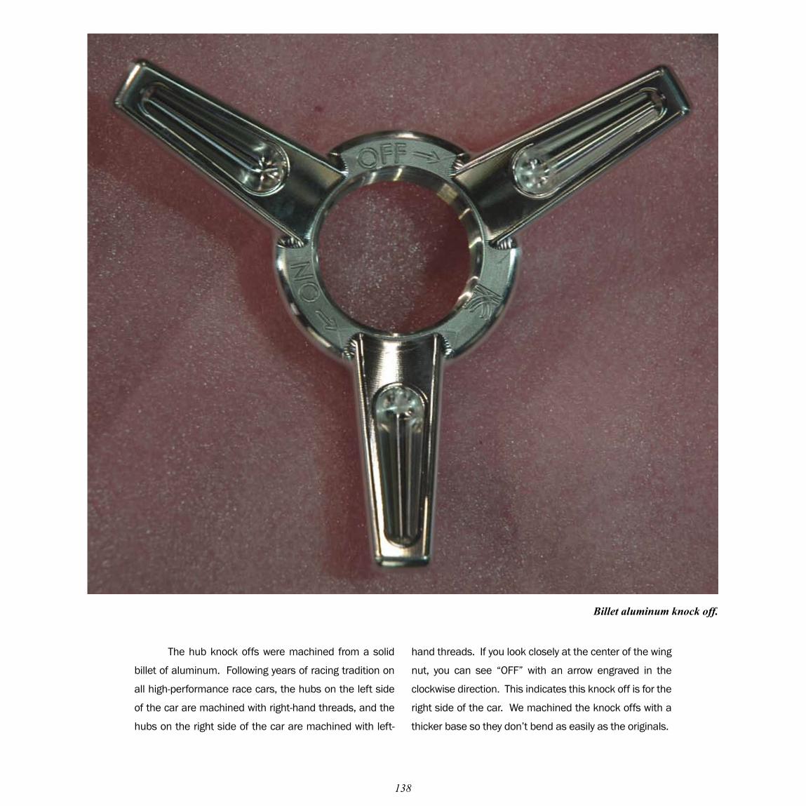
The hub knock offs were machined from a solid
billet of aluminum. Following years of racing tradition on
all high-performance race cars, the hubs on the left side
of the car are machined with right-hand threads, and the
hubs on the right side of the car are machined with left-
Billet aluminum knock off.
hand threads. If you look closely at the center of the wing
nut, you can see “OFF” with an arrow engraved in the
clockwise direction. This indicates this knock off is for the
right side of the car. We machined the knock offs with a
thicker base so they don’t bend as easily as the originals.
139
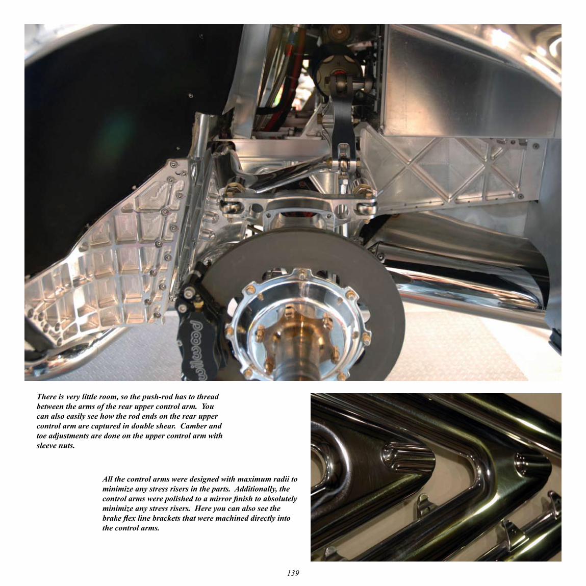
There is very little room, so the push-rod has to thread between the arms of the rear upper control arm. You can also easily see how the rod ends on the rear upper control arm are captured in double shear. Camber and toe adjustments are done on the upper control arm with sleeve nuts.
All the control arms were designed with maximum radii to minimize any stress risers in the parts. Additionally, the control arms were polished to a mirror finish to absolutely minimize any stress risers. Here you can also see the brake flex line brackets that were machined directly into the control arms.


