42
Sustainable Rail Plan May 2013

Sustainable Rail PlanMay 2013

Sustainable Rail Plan
Los Angeles County Metropolitan Transportation Authority May 2013
Acknowledgment
This document was prepared by ICF International and LTK Engineering under contract through Metro’s Environmental Compliance and Services Department. Technical input was provided by staff in the following departments: Wayside Systems, Systems Engineering, Rail Operations, Facilities Maintenance, Equipment Maintenance, Major Capital Project Engineering, and Procurement.

Sustainable Rail Plan
Los Angeles County Metropolitan Transportation Authority i May 2013
Table of Contents
1 Introduction ........................................................................................................................ 3
2 Background ........................................................................................................................ 4
3 Sustainable Rail Strategies ............................................................................................... 6 3.1 Vehicles and Propulsion ............................................................................................ 8 3.2 Vehicle Auxiliary Systems ........................................................................................ 25 3.3 Vehicle Operations .................................................................................................. 28 3.4 Rail Facilities............................................................................................................ 30
4 Recommendations ............................................................................................................32 4.1 Recommendations for Existing and Impending Procurements ................................. 32 4.2 Recommendations for Bundled Near-, Medium-, and Long-Term Strategies............ 33
References ..............................................................................................................................35
Appendix A: Simulation Inputs ..............................................................................................36 List of Figures Figure 1: Energy split (in kWh) for a two hour operation scenario on the Gold Line, with actual system settings .......................................................................................................................................................... 7 Figure 2: Simulated energy distribution for reduced train size (two cars at AW1) ...................................... 24 Figure 3: Simulated energy distribution for standard train size (two cars at AW1 and one car at AW0) .... 25 Figure 4: Time and distance chart for the simulated peak hour service ..................................................... 37 Figure 5: Graphic representation of the two hour operating period used for energy calculations .............. 38 List of Tables Table 1: Metro policies, plans, and strategies related to sustainability and energy...................................... 4 Table 2: Summary of energy savings from simulated energy efficiency measures...................................... 8 Table 3: Technical specifications of the Mitrac Energy Saver ultracapacitor system ................................. 11 Table 4. Estimated ROI for Trimet on-board energy storage unit, provided by American Maglev ............. 12 Table 5: Distribution of brake energy in the simulated rail vehicle.............................................................. 12 Table 6: Estimated cost and technical specification capacitor-based WESSs ........................................... 16 Table 7: Energy savings as a function of line and regeneration voltage .................................................... 19 Table 8: Simulated energy consumption for standard and lightweight vehicles ......................................... 21 Table 9: Energy and cost savings over various time periods with reduced vehicle weight ........................ 22 Table 10: Energy and cost savings of reduced train size ........................................................................... 23 Table 11. Estimated costs and energy savings of interior lighting options ................................................. 26 Table 12: Short-, medium-, and long term strategies recommended to reduce rail energy use ................ 34 Table 13: Input data for simulations ............................................................................................................ 36 Table 14: Results of the simulated reference operation ............................................................................. 39

Sustainable Rail Plan
Los Angeles County Metropolitan Transportation Authority ii May 2013
blankpage

Sustainable Rail Plan
Los Angeles County Metropolitan Transportation Authority 3 May 2013
1 Introduction As a leader in environmental responsibility, the Los Angeles County Metropolitan Transportation Authority (Metro) is pursuing a variety of sustainability strategies to maximize transportation efficiency, access, safety, and performance while minimizing energy use, consumption, pollution, and waste generation. As recently as 2011, Metro spent $33 million on electricity, with $21 million for propulsion of heavy- and light-rail and $12 million for facility operations (e.g., bus and rail maintenance facilities, layovers, terminals, and headquarters building).
This study examines strategies to reduce energy consumption from rail operations, which account for the majority of Metro’s electricity use, and analyzes the costs and potential energy savings for many of these strategies. Furthermore, this study supports the implementation of Metro’s Energy Conservation and Management Plan (ECMP). The ECMP presents a strategic framework to guide sustainable, cost-effective, and efficient energy use throughout Metro’s operations and facilities. This study supports the ECMP goals by identifying strategies that directly reduce energy used by rail operations, auxiliary systems, propulsion, and facilities. The recommendations provided in this study expand upon those outlined in the ECMP. Specifically, this study provides detailed recommendations that apply to the ECMP sections regarding key equipment upgrades and powerful sustainability and investment-grade opportunities to explore. While the ECMP addresses Metro’s broader energy use and procurement strategy, this study specifically addresses the rail system and analyzes in detail the energy efficiency opportunities within Metro’s rail equipment and operations.
The body of this study consists of four sections. The following section describes Metro’s sustainability efforts to date, and discusses how this study furthers those efforts. Section 3 discusses energy-saving strategies, grouping them into four categories based on the aspect of Metro’s rail systems to which they relate:
Vehicles and Propulsion
Vehicle Auxiliary Systems
Vehicle Operations
Rail Facilities
For each strategy, the report gives an overview of the strategy, describes what other transit agencies are doing, and discusses costs, energy impacts, and the timeline for implementation.
Section 4 recommends approaches for Metro to take regarding existing and impending procurement, as well as packages of strategies for implementation over the short, medium, and long term future based on costs, feasibility, and energy savings.

Sustainable Rail Plan
Los Angeles County Metropolitan Transportation Authority 4 May 2013
2 Background Over the past five years, Metro has been working to make all aspects of its operations more sustainable and this study represents the latest step in this effort. As noted previously, one of the major efforts to date has been the development of Metro’s guiding ECMP. The ECMP analyzes Metro’s energy use, demand, rates, and supply. Energy use profiles and the various procurement options are explored, in terms of both rate structures and supply contracts available to the agency. Second, the ECMP identifies opportunities for improved energy management and energy efficiency. Lastly, the ECMP presents several strategies in order to effectively manage energy demand and supply, which includes creating an Energy Management Program that centralizes the coordination of energy management functions and activities. In the context of this study, the ECMP estimates that energy use for rail propulsion will increase 90% by 2020.
To date, Metro has adopted several other plans, policies, and strategies that address energy efficiency, ranging from comprehensive policies establishing sustainability as a general goal for the agency to plans addressing specific energy saving actions, which are summarized in Table 1 and discussed in more depth below.
Table 1: Metro policies, plans, and strategies related to sustainability and energy
Policies
2007 Energy and Sustainability Policy
2009 Metro Environmental Policy
2011 Renewable Energy Policy
Plans 2008 Sustainability Implementation Plan
2011 Energy Conservation and Management Plan
Studies 2010 Greenhouse Gas Emissions Cost Effectiveness Study
2012 Sustainable Rail Scoping Plan
The Metro Board of Directors (“Board”) first adopted the Energy and Sustainability Policy in 2007 to chart a path toward reducing energy consumption and embracing energy efficiency, energy conservation, and sustainability. Later the next year, the Board adopted the Sustainability Implementation Plan, which identified short-term sustainability projects and general guidelines for longer-term projects. Then in 2009, Metro adopted the comprehensive Metro Environmental Policy, which provides guidance on:
Identifying potential environmental impacts generated by our development activities and developing mitigation measures to address those impacts
Operating and maintaining Metro vehicles and facilities to minimize negative impacts on the environment
Reducing our consumption of natural resources
Reducing or eliminating the use of hazardous materials

Sustainable Rail Plan
Los Angeles County Metropolitan Transportation Authority 5 May 2013
Increasing the amount of recycling and use of recycled products
Reducing and/or diverting the amount of solid waste going to landfills
More recently, in 2011 the Board passed a motion to establish the Renewable Energy Policy. This policy called for creative renewable energy solutions and a review of the technical feasibility for off- and on-track renewable power projects on Metro property and infrastructure, including canopies, substations, parking lots, park and rides, landscaped areas, utility poles, tunnels, garages, and maintenance buildings. In 2011, Metro also developed the Energy
Conservation and Management Plan. This plan provides a blueprint to direct Metro’s overall energy use in a sustainable, cost-effective, and energy efficient manner. It also addresses energy used for vehicle propulsion and includes recommendations to improve the management of propulsion energy.
Metro has also developed several other studies that outline potential strategies for greenhouse gas reduction and address Metro’s sustainability including the Greenhouse Gas Emissions Cost
Effectiveness Study. This report analyzed several rail energy efficiency strategies, including wayside and on-board energy storage. The Sustainable Rail Plan goes one step further, examining several additional options to reduce energy consumption from rail operations, which account for the majority of Metro’s electricity use, and analyzing the potential energy savings from many of these strategies.
To date, Metro has planned several projects to reduce energy consumption on rail lines. For example, Metro awarded in November 2012 a contract to VYCON for a 2 MW flywheel energy storage system which stores energy generated by braking trains and redistributes it to rail lines as needed. This wayside storage system will be built at the Red Line’s Westlake/MacArthur Park Station. Similarly, Metro is also planning a 1 MW flywheel system on the Gold Line in Highland Park.
The Agency has also undertaken a multi-year project to replace tunnel lighting along the Red Line. The current lighting fixtures are T12 and T8 fluorescent tubes that use between 64 and 78 watts per fixture and require replacement every 2 years, whereas new LED fixtures being installed will use only 28 watts per fixture and require replacement every 10 years. Over 8,000 fixtures retrofits are planned by 2014. Metro is testing LED lighting at its subway platforms as well as part of an effort to increase safety and reduce energy consumption. Metro has also completed lighting retrofits in the Division 20 shop and is planning comprehensive lighting retrofits at two more of its Divisions as part of the FY14 Capital Program.
Additionally, Metro is also currently piloting the Mass Air Flow Collection Equipment (MACE). This project consists of the design and testing of a self-contained turbine system that can be installed on the wall of the subway tunnel. Initial findings indicate that power generated from wind of passing subway trains can be used to offset energy demand from lighting, rail propulsion, or other uses, lowering overall energy demand.
These projects provide examples for understanding the costs, energy savings, and co-benefits of energy reduction measures that the agency may pursue in the future.

Sustainable Rail Plan
Los Angeles County Metropolitan Transportation Authority 6 May 2013
3 Sustainable Rail Strategies The subsections below present a combination of qualitative and quantitative discussions regarding the feasibility, cost, and energy reduction potential of various strategies to enhance the sustainability of Metro’s rail system.
The quantitative analysis is based on modeling performed by LTK Engineering. Using its proprietary software, RR©LTK, LTK simulated various energy saving options for vehicles operating along the Gold Line alignment from Union Station to Sierra Madre as a reference case.1 Appendix A contains details on the inputs and results of the simulation. This simulation allowed ICK/LTK to quantify the expected results with some certainty and produce an analysis of energy impacts that is comparable between strategies. All energy savings are compared to the total energy consumed at the substation unless mentioned otherwise.
Some of the operational energy savings measures are a result of very basic considerations. Quantifying the energy savings is difficult in such cases. It is obvious that energy can be saved, but the savings depend on a variety of different circumstances that are not easily validated theoretically. An example is the strategy of allowing passengers to open vehicle doors individually as needed instead of having the driver open all doors at each station. Opening side doors only when needed by a passenger will minimize the hot air entering the vehicle at each station. If cost and energy savings potential are not discussed in substantial detail for a particular section, then there are no reliable data to report for the strategy.
The split of all energy sources and energy sinks in the reference case is shown in Figure 1. The red portion of the energy split shows the energy supplied by either the substations (10,658 kWh; 90.2%) or the vehicles in regenerative braking mode (1,162 kWh; 9.8%). All other colors show the simulated system loads: The biggest part of this energy is consumed by the propulsion system to move the vehicle (dark blue) followed by the auxiliary loads (yellow). Distribution losses (841 kWh; 7.2%) are shown in green (return rail losses), violet (overhead connecting system losses) and light blue (feeders/breakers losses).
1 The line from Union Station to Sierra Madre was used for the energy calculation because the data base for the simulations was already set up. LTK used these simulations to investigate traction power issues along this line a few years earlier.

Sustainable Rail Plan
Los Angeles County Metropolitan Transportation Authority 7 May 2013
Figure 1: Energy split (in kWh) for a two hour operation scenario on the Gold Line, with actual system settings
Source: LTK modeling using LTK RR v16.8.0.0
Table 2 lists the measures that were found to be the most effective in saving energy of those considered in the analysis, in descending order of effectiveness.
Regen1,162
Substations10,658
Feeders/Breakers39
Aux Loads1,508
OCS/Third Rail594
Propulsion9,471
Return Rail208

Sustainable Rail Plan
Los Angeles County Metropolitan Transportation Authority 8 May 2013
Table 2: Summary of energy savings from simulated energy efficiency measures
Energy Saving Option Description Potential Savings
Reduced Train Length Removing vehicles from a train when passenger loading is low saves the most energy by far. Running a two car train instead of a three car train with the same passenger loading reduces the energy consumption by about 30%.
~30%
On-board Energy Storage On-board storage can save energy up to about 20%. However, this percentage depends heavily on the already existing capability to regenerate energy to other vehicles.
5 to 20%
Wayside Storage Wayside energy storage systems (WESS) can achieve savings similar to on-board storage. Investment costs tend to be higher than for on-board storage systems, but since the space is typically less limited, a WESS can be designed more generously and therefore is better suited to also reduce peak-power consumption. This allows cost savings in addition to energy savings.
5 to 20%
Increasing Regeneration Voltage Increasing the regeneration voltage allows greater regeneration efficiency. However, a substantial investment to upgrade wayside components and existing vehicles would be needed to achieve these savings. The efficiency also depends on the actual receptivity of the line.
< 20%
Friction Brake Blending The energy savings from friction brake blending depend very much on the receptivity of the line. Without regenerative braking, savings will be nonexistent. The better the line receptivity during regenerative braking, the greater the energy savings.
< 5%
Car Weight Reduction Car weight must be watched closely for new car procurements. Savings of approximately 1000 lbs can result in energy savings of about 1% (at best; less if regenerative braking is available).
< 1-2%
Table 2 does not include several strategies related to vehicle auxiliary systems, vehicle operations, and facilities because of the challenge of quantifying the savings from these strategies using the simulation-based analysis discussed above.
3.1 Vehicles and Propulsion
3.1.1 Energy Storage
Overview
This strategy increases energy efficiency by using energy storage technology to capture the electricity produced by dynamic braking, store that energy in an on-board device, and release the energy to power the train partially during acceleration. On-board energy storage is already in use by some European rail transit agencies, and several agencies in the United States are considering it. Currently, Metro light rail and heavy rail cars rely on dynamic braking, which feeds energy generated by braking back into the line or catenary. However, if no other train is nearby to absorb this re-generated energy, it is burned off by resistors. On-board energy storage systems would capture this excess energy for later re-use.

Sustainable Rail Plan
Los Angeles County Metropolitan Transportation Authority 9 May 2013
Energy storage systems can also be located at the wayside; wayside systems are discussed in Section 3.1.3. These systems are complex, and many different options are available to transit agencies, each of which has its own advantages. Three major parameters define an energy storage system:
Energy storage capacity, which is determined by the size and energy density of the storage technology.
Power rating, which is the maximum current that can be transmitted between the line and the storage device.
Load cycles, or how many charging cycles can the storage system handle over its lifetime.
Four different energy storage technologies are being offered by the industry:
Flywheel systems are the oldest from of energy storage, and have been in use since the 1960s. At the core of these systems is a flywheel that rotates faster as it receives energy from braking vehicles and then acts as a generator during discharge. In order to maximize energy storage while minimizing the size and weight of the system, the flywheel rotates at high speed, operating in a vacuum enclosure with magnetic bearings to reduce friction. Flywheels provide the most load cycles of any storage system, but also require sophisticated control circuits and extensive maintenance. Flywheels are best suited for wayside storage, since they can interfere with vehicle movement and operations unless complex and costly measures are taken to mitigate these impacts. On-board flywheels also pose potential risks to the public should they fail or come loose.
Batteries have high energy density, and battery technology has improved substantially over the past few years. However, batteries have a limited number of load cycles, and must be relatively large and heavy in order to accommodate typical power cycles in a rail system. For this reason, they are best suited for wayside energy storage systems (WESSs) rather than on-board systems. Large battery storage systems that would be capable of handling power cycles on rail lines are currently being tested to store energy generated by wind or solar power. The one instance where batteries are a feasible on-board energy storage technology is in light, low speed street car systems, which generate less energy when braking, allowing for an on-board battery that does not exceed weight limits. Streetcars such as the Alstom Citadis, which operates in Nice and Bordeaux, or the Kawasaki test vehicle SWIMO2 contain on-board battery energy storage systems.
Capacitors, like batteries, have also seen dramatic technological improvements over the past several years. The latest generation of capacitors, sometimes called supercapacitors or ultracapacitors, are double layer electrochemical capacitors with a capacitance on the order of thousands of Farads per cell. They are capable of delivering large amounts of energy at high rates, and can rapidly be discharged and recharged to be ready for the next energy delivery. These capacitors last longer and provide up to 10 times more power than batteries,
2 SWIMO is Kawasaki’s next generation of light rail vehicle; they report that the name stands for “Smooth-WIn-Mover”. More information is available online at: http://www.kawasakirailcar.com/overview-of-swimo.html

Sustainable Rail Plan
Los Angeles County Metropolitan Transportation Authority 10 May 2013
and are more compact and lower-maintenance than flywheels, and are more efficient than either. Their relatively high energy density, low weight, and high power rating makes capacitors ideal for on-board energy storage. Several capacitor-based energy storage systems, including the Bombardier Mitrac on-board storage device and Siemens’ wayside Sitras SES (static energy storage) system, have been used in transit systems in both the U.S. and Europe, and can be considered service proven.
Hybrid storage packs use capacitors to handle the large currents generated during braking and batteries to store the resulting energy. Such units are used for vehicle on-board energy storage, because they optimize weight and size. Siemens has created a hybrid-based system called Sitras HES (hybrid energy storage).
3.1.2 On-board Energy Storage
Overview
There are three major advantages to on-board energy storage:
1. According to information provided by Metro and the manufacturer, ABB Technologies, this technology results in an average 15% reduction in electricity use. The effectiveness of this technology varies greatly depending on the drive profile of each rail car – specifically the amount of braking and acceleration used along the route to stop at stations and overcome grades.
2. The peak power demand of the vehicle is substantially reduced. This reduces voltage sag along the catenary and, as a result, reduces power losses in the substation and along the catenary, creating additional energy savings. Cutting peak power will also reduce energy costs, since billing is typically based on peak power demand. If a rail system is designed around on-board energy storage, it can reduce the need for substations and allow for a lighter catenary design, saving money. On existing lines, on-board storage would allow for increasing service frequency without upgrading the existing wayside power systems.
3. Unlike WESSs, no changes to wayside equipment are needed. The vehicles with an on-board energy storage unit can operate on all lines anytime and they can mix with any other vehicles. Vehicles with and without on-board energy storage can also operate as multiple units, thus even storing some of the brake energy of the non-equipped vehicle, depending on the size of the storage unit.
The disadvantage of on-board energy storage systems is that they add more equipment to the vehicle and increase the vehicle weight. To optimize weight and capacity, on-board storage systems might not necessarily be designed to capture all the brake energy, expecting that part of the regenerated energy will be absorbed in the traditional way by other vehicles on the line. However, the energy needed to accelerate the additional weight is often more than compensated with the improved energy efficiency resulting from the on-board energy storage.
Metro may consider adding on-board energy storage equipment to existing vehicles or specifying it for new vehicles. In both cases, space and weight are important factors, especially on the Green Line, where the axle load over some bridges is limited. On-board energy storage units operate in parallel with the brake resistors. They can be mounted on the roof or under the

Sustainable Rail Plan
Los Angeles County Metropolitan Transportation Authority 11 May 2013
floor of a vehicle. On the P2000 vehicles, roof space on the B car is available. On the P2550 cars, space on the A and B car is available for an energy storage unit. Mounting the unit under the floor would be too costly on all vehicles, because space is not readily available. In either case, the weight and balance characteristics of the vehicle must be considered when adding new devices. As a reference for weight and space requirements, Table 3 shows the technical data of the Mitrac Energy Saver ultracapacitor system marketed by Bombardier.
Table 3: Technical specifications of the Mitrac Energy Saver ultracapacitor system
Mitrac Energy Saver Ultracapacitor
Weight: 428 kg
Energy storage: 1 kWh
Max Power: 300 kW
Dimensions: 1700x680x450 mm
Typically one such box is installed per vehicle. Since the two traction inverters are connected on the high voltage side through the common High Speed Circuit Breaker (HSCB), one storage device can store the brake energy of both trucks.
Adding a roof mounted energy storage system for the P2000 and P2550 would not require an unreasonable effort because roof space is available, and could be accomplished within a year. Due to the age and the complexity of the forced commutated chopper controls of the P865/2020 vehicles, adding on-board energy storage is not recommended for these vehicles. If on-board storage is considered for the Red Line, it should be done concurrently with a refurbishment of the vehicles only, since no under floor space is readily available.
What Other Agencies Are Doing
In May 2012, TriMet finished equipping one of its Type 3 vehicles (S70) with an on-board energy storage device. After testing and collecting energy saving data, TriMet now plans to equip all 27 vehicles of the Type 3 fleet with on-board energy storage. The project is funded entirely by a federal TIGGER grant, and requires investment from TriMet. The contact person at TriMet is Mr. Jason Grohs. The equipment supplier is American Maglev Technology, which subcontracts to Temes (a Transtechnik spin-off) for the system design, and Marathon Power is tasked to design and build the controls. It took TriMet nine months to design, build, install and test the prototype roof mounted energy storage device.

Sustainable Rail Plan
Los Angeles County Metropolitan Transportation Authority 12 May 2013
Costs
TriMet is allocating approximately $ 4.2M for 27 on-board energy storage units, not including vehicle modification costs and maintenance over expected the life cycle. Table 4 shows the estimated order of magnitude of return on investment from this system.
Table 4. Estimated ROI for Trimet on-board energy storage unit, provided by American Maglev
Parameter Value
Energy Rating 0.7 kWh
Power Rating 700 kW
Investment ~$155,000 per car (equipment, only)
Estimated ROI 20 yrs
The payback period of about 20 years is quite long. Similar considerations, and the increase in vehicle weight resulting from the energy storage unit, convinced BART recently to remove the requirement for on-board energy storage from the specifications of its new 700 car fleet.
Energy Impacts
The energy savings achievable with on-board energy storage depend to a large degree on how the existing system is operated. The possible energy savings are a function of the actual receptivity of the line. The more receptive the line, the less additional energy will be saved on-board. Table 5 shows the brake energy distribution for the simulated base case.
Table 5: Distribution of brake energy in the simulated rail vehicle
Parameter Energy Consumption Energy savings
Friction Brake and Train Resistance 2,171 kWh 35%
Rheostatic Brake Resistor 2,751 kWh 45%
Regenerated to the Line and Auxiliaries 1,162 kWh 20%
Total Brake Energy 6,091 kWh 100%
Theoretically an on-board storage device could harvest the 45% of the total brake energy that is dissipated by the brake resistors, in addition to the 20% already regenerated. However, conversion losses to store the energy and feed it back to the vehicle will be about 15%. Therefore the additional energy saving on the vehicle will be 38% in the best case scenario for the simulated peak hour revenue service.
It is important to note that the above figures only consider energy used by the vehicle, not the total system, and are based on an ideal scenario. At the substation, the total regenerated energy will increase from the current 10% to about 30%, so the resulting system-wide energy savings will be 20% at best. If other strategies are employed to increase traditional regeneration, such as increasing the regeneration voltage along the line, the additional savings

Sustainable Rail Plan
Los Angeles County Metropolitan Transportation Authority 13 May 2013
will decrease to between 7% and 10% under the simulated scenario. TriMet was already regenerating 70% of the dynamic braking energy from its cars, so the agency designed its on-board storage systems with a rather low capacity of 0.7 kWh per vehicle. TriMet’s on-board storage system increased the dynamic brake energy recovery to 90%, resulting in a system wide energy savings of about 7%. Decreasing vehicle headways would also increase the effectiveness of traditional regeneration and diminish the energy savings from on-board storage. As a result, on-board storage is more effective at saving energy during off-peak service.
Since vehicles with on-board energy storage can still regenerate energy to the line as well, the on-board storage system does not have to be designed to accommodate the maximum brake energy. If more energy is regenerated to the line, the on-board energy storage system can be smaller and more affordable.
On-board energy storage systems can also reduce the energy consumed by auxiliary systems on Metro subway cars. The brake resistors on these cars heat the air underneath the vehicle, which is used to cool the air-conditioning compressors. When the cooling air is warmed by the brake resistors, it increases the energy consumed for air conditioning. On-board energy storage systems will reduce the amount of energy dissipated to the resistors, resulting in cooler air under the car and more energy-efficient HVAC systems.
3.1.3 Wayside Energy Storage Substations
Overview
Traditionally, regenerative braking energy is transferred to a third rail or overhead catenary, where other railcars can utilize the regenerated power while accelerating. If the regenerated power cannot be used by nearby railcars, it is dissipated through on-board resistors. The installation of a WESS at the substation to store the regenerated energy temporarily on the wayside at locations where the line voltage needs support, instead of dissipating it on the vehicle, can result in substantial energy savings. WESSs utilize the same technology as on-board storage systems; for a discussion of this technology see the overview in Section 3.1.1 above.
WESSs are generally seen as an alternative to on-board energy storage units. While On board storage system typically are operated in one mode, to save as much energy as possible, WESSs are operated in varying modes allowing transit operators to prioritize energy savings or optimize electricity use along the rail system in other ways.
Energy Saving Mode: This mode results in the maximum energy savings. The WESS is operated at no or low energy content, and is always ready to accept all excess power regenerated to the line.
Voltage Stabilization Mode: In this mode the WESS is operated to always have excess energy stored, so that it can be fed back to the line as soon as the line drops below a minimum voltage. If the line voltage returns to the normal operating range, the WESS is recharged, even if the power is provided by the substation rather than by regenerating vehicles. Voltage stabilization mode saves less energy overall, but offers the following co-benefits:
Sustainable Rail Plan
Los Angeles County Metropolitan Transportation Authority 14 May 2013
Peak Power Reduction: The peak power demand is reduced. Reducing the peak power demand can have a significant impact on energy cost, since most utilities consider the peak power demand in setting up the cost per kWh.
Substation Reductions: Operating the WESS in the voltage stabilization mode can require fewer substations along a line.
Service Frequency Increase: Adding a WESS in the voltage stabilization mode allows operators to increase the operating frequency and reduce headways without upgrading existing substations.
A WESS can be operated in different modes at different times of the day in order to maximize economic benefits. For example, the energy saving mode can be selected during off-peak service when traditional regeneration is less effective at conserving energy and line voltage is generally more stable. During peak hour service, more trains can absorb energy generated back to the line through traditional regeneration, so it is preferable to operate the system in voltage stabilization mode, cutting costs by reducing the peak power demand and the need for additional substations.
The advantages of WESS over on-board storage are as follows:
There are no weight limitations because the equipment is stationary.
There are fewer space restrictions. The lack of weight and space restrictions allows transit operators to design an optimal energy storage system.
More energy can be stored than in on-board equipment.
Operating a WESS in voltage stabilization mode has several cost-saving co-benefits, allowing transit agencies to reduce peak power consumption or avoid installing new substations.
The disadvantage of a WESS is that the overhead contact system (OCS) and rails still see all the traction power current dynamics and must be designed for the same maximum currents as without energy storage. In other words, wayside losses remain equal, compared to operating without any storage system.
Planning and implementing a WESS involves acquiring real estate if right-of-way that may not be available, planning and constructing the building to house the storage unit, building the connections to the line, and purchasing and installing the unit. The process would likely require one to two years at a typical location, but could take longer in locations where a transit agency must purchase real estate to accommodate the WESS. Therefore, if a WESS is added to an existing system it will most likely be placed near a train station or a substation where the transit agency already owns real estate and the additional wiring and switchgear can be kept to a minimum. Siemens indicates that the space requirement for a 3 kWh ultracapacitor storage system is about 27 square feet, which does not include access and building requirements.
Metro is installing a flywheel-based WESS with a 2 MW power rating and approximately 8 kWh of energy storage at the Westlake/McArthur Park, which serves the Red and Purple Lines. The system is provided by VYCON and funded through a $4.5 million TIGGER grant from the
Sustainable Rail Plan
Los Angeles County Metropolitan Transportation Authority 15 May 2013
Federal Transit Administration. This should provide excellent data to analyze the potential of saving energy on the wayside in an actual Metro operation. Another WESS is planned near Avenue 61 in Highland Park on the Gold Line, which will have 5 flywheels with a total capacity of 1 MW.
What Other Agencies Are Doing
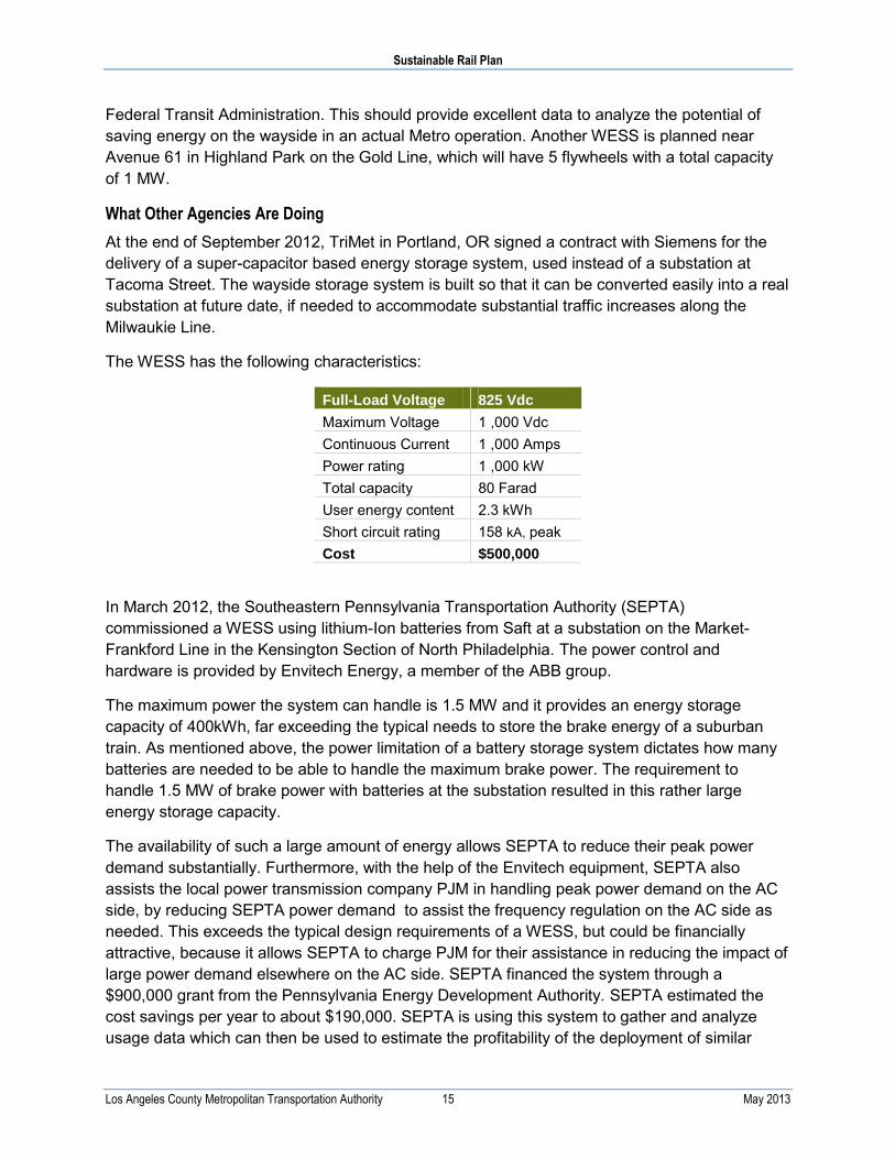
At the end of September 2012, TriMet in Portland, OR signed a contract with Siemens for the delivery of a super-capacitor based energy storage system, used instead of a substation at Tacoma Street. The wayside storage system is built so that it can be converted easily into a real substation at future date, if needed to accommodate substantial traffic increases along the Milwaukie Line.
The WESS has the following characteristics:
Full-Load Voltage 825 Vdc
Maximum Voltage 1 ,000 Vdc Continuous Current 1 ,000 Amps Power rating 1 ,000 kW Total capacity 80 Farad User energy content 2.3 kWh Short circuit rating 158 kA, peak Cost $500,000
In March 2012, the Southeastern Pennsylvania Transportation Authority (SEPTA) commissioned a WESS using lithium-Ion batteries from Saft at a substation on the Market-Frankford Line in the Kensington Section of North Philadelphia. The power control and hardware is provided by Envitech Energy, a member of the ABB group.
The maximum power the system can handle is 1.5 MW and it provides an energy storage capacity of 400kWh, far exceeding the typical needs to store the brake energy of a suburban train. As mentioned above, the power limitation of a battery storage system dictates how many batteries are needed to be able to handle the maximum brake power. The requirement to handle 1.5 MW of brake power with batteries at the substation resulted in this rather large energy storage capacity.
The availability of such a large amount of energy allows SEPTA to reduce their peak power demand substantially. Furthermore, with the help of the Envitech equipment, SEPTA also assists the local power transmission company PJM in handling peak power demand on the AC side, by reducing SEPTA power demand to assist the frequency regulation on the AC side as needed. This exceeds the typical design requirements of a WESS, but could be financially attractive, because it allows SEPTA to charge PJM for their assistance in reducing the impact of large power demand elsewhere on the AC side. SEPTA financed the system through a $900,000 grant from the Pennsylvania Energy Development Authority. SEPTA estimated the cost savings per year to about $190,000. SEPTA is using this system to gather and analyze usage data which can then be used to estimate the profitability of the deployment of similar

Sustainable Rail Plan
Los Angeles County Metropolitan Transportation Authority 16 May 2013
systems, strategically located along their alignments. SEPTA recently received a $1.5 million federal grant to build a second system and is planning to build in total 10 such WESS on its busiest line. At this time it is unclear what SEPTA’s estimated return on investment is for this project; however, the results will help inform other policymakers at other transit agencies such as Metro.
Costs
Table 6 contains information on the energy rating, power rating, and estimated cost of two different capacitor-based WESSs. These figures do not include real estate and installation costs; only the cost of the WESS itself.
Table 6: Estimated cost and technical specification capacitor-based WESSs
Manufacturer Energy Rating Power Rating Estimated Cost
IMPulse/Envitech 2 kWh 750 kW $325,000
Siemens 2.5 kWh 1 MW $800,000
The cost of a 3 kWh WESS is roughly similar to those of a small (~350 kW) substation, but providing energy to the WESS would cost less. In general, if a WESS is built into a system, fewer substations would be necessary, but adjacent substations would need to provide more power to compensate for the relatively low lower power rating of the WESS.
Most WESS units in service are prototypes purchased with the support of federal funding. It seems that the energy saving benefits of a WESS are not commercially attractive at current energy costs although the possibilities of saving energy and stabilizing the line voltage provide clear benefits. In order to achieve a return on investment from WESSs, it is important that transit agencies operate the system to reduce costs by stabilizing the line voltage and reduce peak power demand (which is the objective of Metro’s Gold Line WESS installation).
Energy Impacts
Theoretical estimates for WESSs are often higher, but they sometimes neglect the fact that an existing system already saves some energy due to traditional regeneration between vehicles and feeding auxiliary vehicle loads. The range of potential energy savings is similar to the overall savings achieved by on-board storage devices. WESSs can have greater energy storage capacity than on-board systems, but unlike on-board storage systems WESSs cannot reduce losses along the OCS and rail.
An extensive test of a WESS was performed with a 1 MW, 5 kWh storage station in Hannover, Germany in 2004. The system reduced annual energy consumption by approximately 18% compared to the year prior to the installation of the WESS.
Other results from WESS systems have shown fewer benefits. Sacramento Regional Transit installed a battery energy storage system on its Folsom Line in 2007 and removed it after the initial trial period since no significant energy savings were achieved. Original estimates had predicted energy savings of up to 280 MWh per year for the system. The system did stabilize

Sustainable Rail Plan
Los Angeles County Metropolitan Transportation Authority 17 May 2013
voltage and reduce peak power demand, but since peak power costs still varied greatly, the resulting cost savings were difficult to estimate.
3.1.4 Bidirectional Substations
Overview
Substations are mostly unidirectional, converting AC power from the public grid to DC power for use in the rail system. However, substations can be designed to be bidirectional, which would allow the utility to buy back excess energy generated by braking vehicles on the DC side, ensuring that none of this energy went to waste. This measure is currently not considered feasible, because the varying power availability makes it challenging for utilities to buy back fluctuating power from consumers. The advance of SMART grid technologies and an increase in electricity costs may make this strategy feasible over the long term.
3.1.5 Changing the Line Voltage
Overview
All Metro rail vehicles have the capability to regenerate brake energy to the line. If the line is non-receptive (meaning no other vehicles are consuming power at the time a vehicle is braking), then only the on-board auxiliary loads of the braking vehicle are powered by regenerative braking, which means that roughly 95% of the braking energy is lost. Three factors influence the receptivity of the line:
Headways: The shorter the headways, the more likely it is that other vehicles will be drawing power from the line in the vicinity of a braking vehicle.
Regeneration Voltage: the OCS system is specified for an operational voltage range within the system can operate safely. The upper limit of this range is called the regeneration voltage, because it is the maximum voltage at which vehicles can regenerate electricity back to the OCS without overwhelming the circuitry. When the line voltage reaches the regeneration voltage, vehicles switch from feeding energy to the line to dissipating it through the brake resistors.
No-load voltage: the no-load voltage is the voltage at which substations are designed to operate when there are no trains on the line. The difference between the regeneration voltage and the no-load voltage determines how much electricity trains are able to feed back into the line.
Headways are determined by ridership demand, so reducing headways is not considered an energy saving strategy. Decreasing the no-load voltage will increase the amount of energy that vehicles can feed back into the system, but will also decrease the length of the line that can be fed by each substation, so if the no-load voltage is too low it will require more substations along each line. Increasing the regeneration voltage up to the limits permitted by vehicles and wayside equipment will also increase the efficiency of regeneration.
The rail lines operated by Metro are designed for a nominal 750 Vdc line voltage. The operational voltage range is typically specified as 525 to 900 Vdc, with a no-load voltage of 850

Sustainable Rail Plan
Los Angeles County Metropolitan Transportation Authority 18 May 2013
Vdc at the substation. Metro light rail vehicles begin to transfer some brake power to the brake resistors when the line voltage reaches approximately 875 Vdc. The transition to the brake resistor is completed at approximately 925 Vdc, depending on the vehicle type.
An international standard, IEC 60850, was developed in the mid-1990s that allows vehicles to regenerate for a short time at a higher line voltage than the traditionally used voltage range for a 750 Vdc system like Metro’s. This standard allows increasing the regeneration voltage on a vehicle for up to 5 minutes to 950 or even 1000 Vdc during regenerative braking. Therefore, even if the no load voltage of the substation is set at 850 Vdc, the vehicles still can achieve a line voltage increase of 150Vdc to better re-use the regenerated energy.
The benefit of increasing the maximum regeneration voltage is that it can be a relatively low-cost way to increase the energy efficiency of a rail line. The disadvantage is that the strategy will be impossible to implement or will create technical challenges unless all vehicles or equipment on the line are compatible with the increased voltages. Most vehicles currently in use by Metro are designed to operate with a 925 Vdc peak regeneration voltage. The exception is the P2550, which is designed to handle a higher regeneration voltage of 950 Vdc, but its maximum regeneration voltage is controlled by software to be compatible with the existing vehicles and the wayside overvoltage protection systems. The future P3010 vehicles are also specified to be able to provide higher regeneration voltages in compliance with IEC 60850.
The Gold Line, which is currently operated as an isolated system, would allow increasing line voltage if it operates with P2550 or P3010 vehicles only. Upgrading other alignments will not be possible as long as the P2000, P2020 and P865 cars remain in operation and should be considered a long term solution. However, it is recommended that all new vehicles and wayside systems be built to meet IEC 60850 so that regeneration voltage can be increased in the future.
Even though increasing the line voltage on the Gold Line is feasible in the short term, it would require additional efforts to review and retrofit the power system along the line in order to ensure safety and achieve maximum possible energy savings. Investigation with the Metro Engineering Department revealed that the surge arrestors in use along the OCS on all lines, including the Gold Line, have a maximum continuous operating voltage of 940 Vdc. This means that the surge arrestors would have to be replaced if the brake voltage was allowed to increase to 950 Vdc or more. The replaced arrestors could become spares for the other lines until such time as the regeneration voltage is increased on all lines. Other critical items to be addressed before implementing higher voltage include the ground fault protection and the substation circuit breaker. Indeed, all elements of the power system will need to be reviewed before any steps are taken to implement higher voltages. Metro will also have to collaborate with AsaldoBreda, the manufacturer of the P2550 vehicles, to update the vehicle software. Another obstacle is the interoperability with other lines through the Regional Connector once that line is in service.
Costs
We do not have cost data on this strategy. However, the following aspects of this strategy would involve additional costs:
Replacing surge arrestors if increasing the regeneration voltage to over 925 Vdc.

Sustainable Rail Plan
Los Angeles County Metropolitan Transportation Authority 19 May 2013
Reviewing and upgrading other elements of the power system as needed to accommodate the higher regeneration voltage.
Potentially installing more substations, if the no-load voltage is lowered.
Energy Impacts
Based on a simulation with the P2550 vehicles operating at AW1 on the Gold Line, with a six minute headways between Union Station and Sierra Madre, we estimate that Metro could reduce energy use as follows under different combinations of no load voltage and maximum regeneration voltage. The yellow highlighted row is the simulated current operating condition with a no load voltage setting at 850 Vdc.
Table 7: Energy savings as a function of line and regeneration voltage
No-load Voltage Regeneration Voltage Regenerated Portion of Total Brake Energy at
Vehicle
Energy Savings at Substation
750V No regeneration – –
750V 900V 43% 21%
850V 900V 19% 10%
850V 950V 36% 18%
850V 1000V 45% 23%
Notes:
Total brake energy: 100% of the energy available at brake entry speed. It consists of the energy dissipated by the friction brakes and the brake resistor and the energy regenerated to the line. Energy dissipated by the train resistance is not included, since this energy is always lost.
Energy savings at substation: This is the actual energy savings achieved by the reduced power demand at the substation. This includes all propulsion and auxiliary power as well as all system losses. This percentage is the expected financial savings. For example: if the regeneration feature on the P2550 is disabled, the energy costs would be expected to increase by 10%. Please note that energy cost savings do not represent a net overall dollar savings to Metro, as the costs to prepare the wayside system and on-board changes also have to be considered. Calculation of such costs and the pay-back time based on energy savings are beyond the scope of this report.
The energy savings due to regenerative braking under the current operating conditions is 10%. Lowering the no-load substation voltage to 750 Vdc could save roughly an additional 11% energy due to improved regeneration. Savings of 8-13% could be achieved by allowing the P2550 vehicle to regenerate at 950 Vdc or higher while maintaining the current substation no-load voltage at 850 Vdc.
3.1.6 Brake Blending
Overview
Intelligent brake blending is an energy saving option applicable to three-truck light rail vehicles (LRVs), using friction brakes on the center truck and dynamic brake on the two motor trucks. The traditional approach, as on Metro’s P865, P2020 and P2000 LRVs, is to blend in the friction brakes on the center truck proportionally with the dynamic brakes on the motor trucks. An intelligent brake blending system would give preference to the dynamic brakes on the motor

Sustainable Rail Plan
Los Angeles County Metropolitan Transportation Authority 20 May 2013
trucks over the friction brakes on the center truck, thus first fully using the regeneration capabilities before blending in the friction brakes on the center truck.
With traditional blending, about one third of the kinetic energy of the vehicle is always dissipated into heat by the friction brakes on the center truck. This means that less than two thirds of the energy is converted into electric energy by the traction motors.
The specification for the new Metro P3010 vehicles requires this new intelligent blending approach. Therefore no additional efforts are needed other than supervising the implementation during design reviews. The P2550 vehicles also have some level of this type of brake blending, albeit not as aggressively as specified for the P3010. For older vehicles, such as P2000 and P865, a change of the blending concept is not recommended, due to the cost of modifying the control software. For these vehicles the programming tools are old and might not be readily available. Therefore this measure is suited for new vehicle procurements only.
Since a modification of the existing vehicles is not recommended, this measure will be applied only gradually over the time with the roll-out of new vehicles.
Costs
Since this strategy only requires a change to specifications, the costs of implementation are negligible. In addition to cost savings from reduced energy, this strategy will also save money on maintenance because it will result in less use of the friction brakes on the center truck. For example, the new blending scheme on the P2550 increased the brake pad life from 8,000 miles on the P2000 to 34,000 miles.
Energy Impacts
Theoretically, the regeneration capability could be improved by up to about 25% at the vehicle level with intelligent blending. In reality it will be less, because wheel rail adhesion will limit the useful maximum brake effort per motor truck, requiring blending in the friction brakes on the center truck to avoid sliding motor trucks. A more realistic estimate is that the energy savings will be about 5%, but such percentage also depends on the receptivity of the line or if on-board energy storage devices are used.
3.1.7 Reducing Vehicle Weight
Overview
The impact of the vehicle weight on energy consumption is generally underestimated. Reducing the weight of railcars directly improves energy efficiency. The primary challenge of this strategy is administering contracts with carbuilders to encourage weight reduction without sacrificing safety and durability.
This strategy is difficult to achieve on existing vehicles, because it requires carbuilders to go through extensive weight saving programs while not compromising safety. Therefore, a retrofit on an existing vehicle would not be cost effective. However, if components or parts of these vehicles are replaced during a refurbishment program, special attention should be given to the weight of the replacement parts.

Sustainable Rail Plan
Los Angeles County Metropolitan Transportation Authority 21 May 2013
This strategy is strongly recommended for new railcars. It requires agencies and carbuilders to focus on using new and alternative materials during the design phase, and to look for opportunities to re-design the car structure while still meeting the requirements for the car body strength in CPUC GO143-B, such as for collision and corner posts, truck to carbody attachments, and truck design. In order to accomplish these objectives, new vehicle specification could include financial incentives to encourage the carbuilder to keep the vehicle weight low. For instance, in Europe, the vehicle cost is often compared with the vehicle weight. Vehicles proposed at a lower weight can offset some of the initial costs by the estimated cost savings resulting from energy saved over a 30 year vehicle life. Therefore, a more expensive but lighter vehicle might compare favorably to a cheaper but heavier one. In the process of developing procurement specifications, stiff weight penalties could be developed and applied if the carbuilder exceeds the proposed vehicle weight.
Since weight saving measures can only be applied to new vehicles, no additional time is needed to implement this strategy. The carbuilding industry will have to invest in research and development or incorporate technologies that reduce weight. However, from Metro’s perspective, it simply requires outlining the specific weight requirements through its procurement processes.
Costs
The costs of implementing this strategy depend upon the incentives that transit agencies use to encourage carbuilders to design lighter vehicles. See Table 9 below for an estimate of the potential cost savings due to reducing vehicle weight.
Energy impacts
In order to estimate the potential energy savings due to reducing vehicle weight, simulation of a round trip of a train with two P2550 vehicles was done for segment the between Union Station and Sierra Madre for both the current vehicles and for vehicles that were 500 kg lighter. Table 8 shows the results.
Table 8: Simulated energy consumption for standard and lightweight vehicles
Scenario Actual Weight
(P2550 vehicles)
Substation
kWh
Savings
kWh
baseline 119,709 lbs 464 –
weight reduction 118,628 lbs
(-500 kg)
459 5
Savings of 2.5 kWh per vehicle may not look like much, but considering that a vehicle makes approximately 10 round trips a day, an energy saving of 25 kWh per vehicle per day will result. Since 20 vehicles operate on an average per day on the Gold Line between Union Station and Sierra Madre, this would result in savings of 500 kWh per day. Table 9 shows the energy and cost savings due to reducing vehicle weight by 500 kg, based on a cost of $0.14 per kWh, over different time periods.

Sustainable Rail Plan
Los Angeles County Metropolitan Transportation Authority 22 May 2013
Table 9: Energy and cost savings over various time periods with reduced vehicle weight
Savings per car
and day Savings per fleet and
day Savings per fleet and
year Savings for the design life of
one vehicle
Energy (kWh) 39 780 284,700 427,050
Cost $3.50 $70 $39,858 ~$60,000
These estimates can be used as a starting point for creating incentives to carbuilders for providing lighter vehicles.
It is important to note that the calculations shown above do not consider regenerative braking or other strategies to reduce energy use. Using a fully receptive line or on-board energy storage may reduce the energy and cost benefits of lighter vehicles by approximately one third.
3.1.8 Reducing train length
Overview
In the same way as car weight impacts the energy consumption, so does the number of cars in a train. Running trains consisting of more vehicles than needed requires more energy due to the weight of an additional vehicle. The increased vehicles’ operating miles also increase maintenance costs. An efficient way to optimize train size is to increase it only during rush hour service and reduce it for off-peak service. The easiest way to accomplish this is to drop off vehicles at the end terminals of a line and then couple them up again when needed for the next rush hour service. It is recognized that this is not feasible on certain Metro lines, which are constrained by the available real estate and storage track design. For example, on many of the Metro light rail lines, the shop is somewhere in the middle of the line, or not even along the alignment, as on the Exposition Line. The Gold Line however has some storage room at each end of the line, which would allow storing vehicles during off peak service without any additional construction needed. For future planning, new alignments might include more storage tracks at the end of the line, allowing storage of some vehicles during off-peak hours.
At this time, there is some variation in the length of trains that are run at different times during the day. In general, the cars are taken off the trains during off-peak times, as appropriate.
What Other Agencies are Doing
BART changes the length of its trains on an hourly basis, using trains of up to ten cars during peak-hours and as few as four cars during off-peak service.
Costs
We do not have data on the costs to implement this strategy. The following section contains an analysis of the potential energy and cost savings from reducing train size. Any potential savings need to be compared with the expenses required to split the train and pull the unused cars back into a yard.

Sustainable Rail Plan
Los Angeles County Metropolitan Transportation Authority 23 May 2013
Energy Impacts
A simulation was conducted using current Gold Line conditions to compare the energy consumption of a two car train loaded at AW1 to a three car train transporting the same number of passengers, consisting of two AW1 loaded cars plus one empty vehicle (AW0). The simulation is based on two hours of operation between Union Station and Sierra Madre with six minute headways, and includes regenerative braking. Table 10 shows the results.
Table 10: Energy and cost savings of reduced train size
Train Consist Propulsion Energy Substation Energy
AW1 + AW1 + AW0 13,397 kWh 15,880 kWh 100%
AW1 + AW1 9,471 kWh 10,658 kWh 67%
Energy Savings 3,926 kWh 5,222 kWh 33%
Cost Savings $ 730 per two hours of operation
According to the simulation, reducing train size by one car would reduce substation energy consumption 33%, saving 5.2 MWh of energy over two hours. Assuming that electricity costs $0.14 per kWh, this would save $730 over the two hour period.
Note that in off-peak operation the regenerated energy contributes less to the propulsion power because the trains are geographically further apart, so reducing the train size is more effective in off-peak hours on a per-mile basis. Similar results would be expected across all lines. In particular, the Exposition line has the potential to save energy, since it is currently operated with three car trains although current ridership may not yet require that many cars per train.
Figure 2 and Figure 3 show the energy consumption of an AW1 loaded train consisting of a) a two car train and b) a three car train with the same passenger load (in total <AW1 per car).

Sustainable Rail Plan
Los Angeles County Metropolitan Transportation Authority 24 May 2013
Figure 2: Simulated energy distribution for reduced train size (two cars at AW1)
Source: LTK modeling using LTK RR v16.8.0.0
Regen1,162
Substations10,658
Feeders/Breakers39
Aux Loads1,508
OCS/Third Rail594
Propulsion9,471
Return Rail208
Ground Losses0

Sustainable Rail Plan
Los Angeles County Metropolitan Transportation Authority 25 May 2013
Figure 3: Simulated energy distribution for standard train size (two cars at AW1 and one car at AW0)
Source: LTK modeling using LTK RR v16.8.0.0
3.2 Vehicle Auxiliary Systems
3.2.1 Vehicle Interior Lighting
Overview
There are opportunities to replace older lighting technologies, such as fluorescent lighting with magnetic ballasts, with more efficient lighting in some vehicles. Based on conversations with Metro staff, most interior lighting other than on the P2550 cars is from T12 fluorescent light tubes. In most cases, the low voltage power consumption could be reduced by about 20% by replacing the T12 with more efficient T8 tubes. The T8 tubes can be mounted in the same fixtures as the T12 tubes. Most vehicles already have a high frequency, electronic ballast of greater than 30 kHz which are likely compatible with T8 tubes.
Another option for more efficient lighting is switching to LEDs. However, LED efficiencies are in the same range as fluorescent tubes such as the T8 or T5 fluorescent tubes. The T8 and T5 tubes are also priced much lower than any LED lights with comparable light output. The high cost of LED lights even pushes maintenance costs up higher than for efficient fluorescent tubes. At this time, the only reason to switch to LED lighting would be if there are accessibility issues in
Regen1,720
Substations15,880
Feeders/Breakers90
Aux Loads2,263OCS/Third Rail
1,369
Propulsion13,397
Return Rail480
Ground Losses0

Sustainable Rail Plan
Los Angeles County Metropolitan Transportation Authority 26 May 2013
the placement of the lighting. The expected longer life time of an LED bulb might be beneficial under these conditions.
Costs & Energy Impacts
If we assume that the interior lighting load is about 800 W per car, then a 20% power reduction will result in a power savings of about 160 W. Including conversion losses saved, the power savings at the OCS will be about 180 W. With an average operating time of about 14 hours a day per vehicle (powered-up), we estimate a savings of 2.5 kWh per day or 920 kWh per year.
Table 11 below shows an estimate performed for different lighting options based on a M7 car operated by Metro North. It clearly shows that the costs of the LED lighting do not cut the maintenance costs for interior lighting. This is mainly based on the fact that changing a light tube is fairly easy and similar between T8 and LED tubes. The additional labor used to change fluorescent tubes more often is more than offset by the higher costs of the LED lights.
Table 11. Estimated costs and energy savings of interior lighting options
Cost Factor Conventional Fluorescent
(T12)
High Efficiency Fluorescent
(T5) LED
Installed power
for similar light intensity 1,106 W 729 W 1,130 W
Initial HW costs $3,222 $4,928 $4,800
Maintenance costs / year $48.24 $49.82 $512
Energy costs / year $1,217 $802 $1,243
Maintenance & energy costs
per year $1,265 $852 $1,755
Total cost, 20 yrs 1 $28,522 $21,968 $39,900
Total energy use, 20 yrs 2
(at light fixture) 110,600 kWh 72,900 kWh 113,000 kWh
Total energy use, 20 yrs 3
(at the substation) 152,075 kWh 100,237 kWh 155,375 kWh
1 At current energy and labor costs including initial costs; 2 Assuming 5,000 hours per year; 3 Assuming that conversion losses are about 27% between the substation and the light fixture.
3.2.2 Light Controls
Keeping interior lights off
Currently all vehicles operate with the interior lighting on, as long as the vehicle is powered up. During daylight this is not really necessary. Especially on the Green Line, with no underground stations or tunnels, the lights could be switched off during the day. Note that this strategy is not applicable for the subway.

Sustainable Rail Plan
Los Angeles County Metropolitan Transportation Authority 27 May 2013
Especially for new vehicles, an intelligent light controller could be specified. This controller controls the lights as needed, depending on the exterior light conditions. Additionally GPS route information could be used to identify underground stations and tunnels to switch on the lights before entering these locations and keep the lights on if tunnels / underground stations follow each other in a short distance.
Especially with LED lighting, the interior lights could be dimmed or switched on easily, since they do not need a start-up time.
Running the Green Line without interior lights for about 12 hours a day on average, would save close to 10kWh per day and vehicle. This will result in energy savings per vehicle per year of about 3,650kWh, equivalent to about $511.
Reduce interior light intensity local mode
If the vehicle is parked in local mode, interior lighting could default into emergency lighting after a time delay. A switch, resetting the timer, could be installed for the cleaning personnel to activate all lights as needed.
3.2.3 HVAC Improvements
Overview
There are several opportunities to reduce the energy consumed by heating, ventilation, and air conditioning in rail vehicles. We list several different strategies in this category below; it is important to note that many of them either could be implemented in tandem with other strategies or would decrease in effectiveness in combination with other strategies, and we discuss the particularly important interrelationships with other strategies discussed in this report:
Variable voltage / variable frequency drives for compressors: Typically, HVAC compressors operate only in “on” or “off” mode. As long as the compressor is on it will draw the maximum power and cool the air accordingly. In order to control the temperature of the air inside the vehicle, a heating element re-heats the cold air to the desired temperature before routing it to the passenger area. In some cases, two independently controlled compressors work in parallel for improved power control. Variable voltage / variable frequency drives (VVVFD) can be used to further improve the compressor controls, allowing for the elimination of the re-heat mode, and reducing the energy consumption of the HVAC system when temperatures require less than the maximum level of cooling. Installing VVVFDs is likely only cost-effective when replacing an HVAC system.
Variable Fresh Air Intake: Traditionally, HVAC units mix fresh air in with the return air of the vehicle in order to maintain interior air quality. However, fresh air is typically warmer than return air, so this increases the energy needed to cool the vehicle. If only a few passengers are on-board the vehicle, then the amount of fresh air can be reduced, conserving energy without impacting air quality. The approximate number of passengers on-board is already known to the vehicle controls, because the weight signal, used to adjust the traction and braking effort as a function of vehicle load, provides this information. Therefore the same weight signal can be used to vary the amount of fresh air that enters the vehicle by changing the position of the fresh

Sustainable Rail Plan
Los Angeles County Metropolitan Transportation Authority 28 May 2013
air dampers. Some HVAC units already have such dampers, but typically only two or three damper positions (open, closed or perhaps partially closed) are used. Changing this operation into a continuous positioning of the fresh air dampers is a cost effective improvement for new equipment, considering the vehicle life time. This strategy can also reduce energy use during cooler weather by allowing for the use of fresh air to cool vehicles rather than air conditioned return air. However, refurbishing existing equipment might not be recommended since this strategy also requires a substantial software change. Instead, this strategy is best suited for new cars.
Windows: Windows are also a point of energy loss during hot and sunny days. Vehicle windows in the Los Angeles area should be replaced by windows with a high heat rejection to keep the solar heat-load inside the vehicle low. This can be done during regular window replacements on existing vehicles, and can be specified for new vehicles.
Car Body Insulation: For new vehicles, Metro should ensure that car body side walls provide enough thermal insulation to minimize energy loss. This can be achieved by using more efficient thermal insulation material or by increasing the wall thickness, although the latter approach may not be desirable if it reduced the width of the seating area. During the design of the side wall structure, special care must be given to minimize locations where a heat transfer from the outside to the inside wall can occur. Any such heat transfer location will increase the inside temperature, similar to a heating element. This strategy is best implemented through increasing specifications requirements for insulation on new cars.
What Other Agencies Are Doing
The New York Metropolitan Transit Authority (NYMTA) uses VVVFDs on their R142, R142A, R143, and R160 fleets. Several European transit agencies use variable fresh air intakes.
3.3 Vehicle Operations
3.3.1 Layover Mode
Overview
All light rail vehicles at Metro do have a layover mode which is activated by the cab key in the position “local”. In this position all auxiliaries are kept operational at full capacity while the propulsion is disabled. The cab key can be removed in this position. In most cases, this results in many LRVs being left running and powered up in the yard for hours. It is not uncommon that such vehicles have all the lights on, the HVAC running, and all doors open. This situation wastes energy and can be easily addressed with an operational change and with some vehicle control changes, which can easily be implemented in the new vehicle procurement. On existing vehicles these control changes would require some hardware and software modifications. Especially the software modifications would have to be done by the original equipment manufacturer (OEM), which typically turns out to be a cost driver.

Sustainable Rail Plan
Los Angeles County Metropolitan Transportation Authority 29 May 2013
Operational Changes
Metro could establish yard rules to address vehicles in Layover Mode. For instance, the rule could state that all vehicles coming back from the evening rush hour should be parked completely shut down and all doors open overnight, unless rain is in the forecast. Layovers in the summer during the day should be with doors closed and HVAC running with the fresh air dampers closed, if possible by the vehicle type. This would likely require a dedicated person in charge of tending to the vehicles when in layover at the yard.
Control changes new vehicles
Although the requirements discussed are not part of the new P3010 car specification, it is recommended to address these issues with forthcoming specification review meetings and the preliminary design reviews.
3.3.2 Door Controls
Overview
Modifying the procedure to open all the doors at every transit station has the potential to save energy without any financial investment. Each time that the doors open, conditioned air escapes the train, increasing the energy that must be spent by the train’s HVAC system. On Metro’s light rail lines, there are stations that receive relatively few boardings and alightings, and energy used for cooling is wasted each time the doors open. If the task of opening the door is left to the passenger using the train’s Door Release feature rather than having the driver open all doors on one side, then less cool air will be lost. This strategy will be especially effective on warm days, during off-peak operation and at station toward the end of the route when fewer passengers are boarding. Currently, Metro periodically implements this type of measure. On days when the temperature exceeds 100F, Metro’s operations staff receives notice not to open all doors. However, based on research conducted as part of this Plan, this policy is rarely enacted or enforced.
Costs
This strategy does not require any physical investments, since all Metro light rail vehicles are currently equipped with the local Door Release feature. However, it would require some additional effort to educate passengers about the change, which could be accomplished by adding automated messages to the passenger information system.
3.3.3 Train operation
Overview
Some operators do not maximize train energy efficiency by switching back and forth between excessive acceleration and excessive braking rather than controlling speed by coasting. While some of this behavior is driven by the trains’ Automatic Train Protection (ATP) system, which requires prompt responses by drivers to avoid penalty brake applications, some of it may be avoidable without any adverse impacts on service. Train runtime simulations prove that high

Sustainable Rail Plan
Los Angeles County Metropolitan Transportation Authority 30 May 2013
accelerations followed by high decelerations can easily be replaced by constant speed with little to no impact on trip times.
The first step in identifying opportunities to operate trains more efficiently is to analyze operating behaviors for opportunities to reduce wasted energy. These opportunities could be realized through driver training, as well as through software that is currently available to help guide drivers to operate vehicles more precisely based on track profile, signal conditions and train location. It may also be possible to optimize automatic train operation (ATO) systems for increased efficiency in some cases. For example, ATO systems could be adjusted so that trains pulling into Union Station do not stop before reaching the platform. There may also be opportunities to reprogram the ATO controls in order to increase coasting without impacting the schedule.
For new alignments, it may also be possible to design tracks in order to maximize operational efficiency. One of the operational considerations is already applied on the Red and Purple lines, where the stations are located at a higher level to use gravity to reduce the amount of energy trains need to brake and accelerate. This type of engineering consideration can also work in tandem with regenerative braking systems to enhance the use of energy captured during braking.
Driver training, speed control software, or ATO reprogramming are all low-cost strategies that can be implemented at any time. Design strategies are likely only feasible when Metro is designing a new line.
Costs & Energy Impacts
Due to the variety of strategies that could be considered under this approach and the need to collect further data in order to identify opportunities to save energy, we are unable to quantify the potential costs or energy savings due to more efficient train operation.
3.4 Rail Facilities
3.4.1 Facility Lighting Upgrades
Overview
This strategy reduces energy usage and greenhouse gas emissions by replacing existing lighting in Metro facilities with more efficient and cost-effective equipment. LED fixtures in signals, emergency cut-off lights, tunnel lighting, and other applications can cut energy consumption by up to 75% and also reduce crew maintenance costs. This strategy could be implemented over the next several years by replacing old lighting fixtures at the end of their operating life with new fixtures.
The implementation of efficient “plug and play” lighting fixtures in the 22 mile Red Line subway tunnel was outlined in the GHG Cost Effectiveness Report prepared by ICF for Metro in 2010. The lighting in the subway tunnel is mainly used to illuminate the tunnel for train operators, as well as to illuminate the walkways in case of emergencies, evacuations, and repairs. Currently, an older, less efficient lamp and fixture combination with two four-foot T12 or T8 lamps are used

Sustainable Rail Plan
Los Angeles County Metropolitan Transportation Authority 31 May 2013
in the tunnel. These fixtures typically burn out and need replacement every 2 years. However, because of the trains’ operating schedules, workers are only given between two to six hours at night to repair or replace defective fixtures or install new ones. Since a repair, replacement, or new installation can take up to 20 minutes per fixture, a four person crew can only handle up to six fixtures in each two hour period.
Metro is currently installing “plug and play” technology that can achieve: 1) a reduction in replacement and installation time, 2) a reduction in power and energy usage, and 3) an increase in the life of the lamp and fixture combination. As noted previously, the current lighting uses between 64 and 78 watts per fixture and need to be replaced every 2 years. LED retrofit kits provide significantly more efficient lamp and ballast combinations that use just 28 watts per fixture. These lamps last much longer requiring replacement every 10 years. As of March 2013, Metro maintenance staff have retrofitted about 5% of fixtures in the tunnel. This project should be complete by March 2014.
In the GHG Cost Effectiveness Report, an audit of two of Metro’s facilities showed that two thirds of the current lighting was linear fluorescent T12 lamps, with a lifetime of about 20,000 hours. The newer, more efficient T8 or T5 lamps and fixture combinations and have a lifetime of 24,000 – 36,000 hours and could save up to 30% of energy use for lighting in facilities. Other lighting efficiency opportunities at Metro rail facilities include replacing 1000 watt high pressure sodium fixtures and metal halide fixtures of various wattages. More efficient technologies such as T5 high-output fluorescent, LED’s and induction are being explored as potential replacements.
Costs
An estimate of $153 per fixture is needed to replace a T12 fixture with either a T5 or T8 fixture; and $1,314 per fixture to replace a metal halide fixture with a LED fixture. The California Database for Energy Efficient Resources (DEER) provides a cost estimate of $221 per fixture to replace a standard metal halide fixture with a more efficient halide fixture. Another factor in the determination of costs for facility lighting will be the availability of incentives. Both Los Angeles Department of Water and Power (LADWP) and Southern California Edison (SCE) provide incentives for energy efficiency programs and rebates for installation of energy efficient technologies. Metro has committed to pursuing these rebates whenever applicable. Metro is currently working with the utilities in maximizing these financial incentives.
Energy Impacts
As noted previously, there is up to a 30% energy savings when going from a T12 to a T5 or T8 fixture. The efficient metal halide fixtures and LEDs can save about 35% in energy consumption; whereas LED lighting can reduce energy by up to 75%; however, these estimated energy savings are not always achieved in practice. Ultimately the total energy savings is a function of how many fixtures can be retrofitted and the type of fixture being retrofitted. As part of Metro’s Energy Conservation and Management Plan, comprehensive lighting retrofits at rail divisions are planned for FY14.

Sustainable Rail Plan
Los Angeles County Metropolitan Transportation Authority 32 May 2013
3.4.2 Stationary HVAC Improvements
HVAC improvements for stationary auxiliary services are focused primarily on the HVAC units themselves, rather than the intake and VVVFD units that were discussed previously. HVAC units with improved energy efficiency performance can save money and reduce maintenance at stations and other facilities such as maintenance shops.
A review of current temperature settings and sensor locations is the first step in reducing the energy consumption of existing stationary AC systems. Often temperature sensors are in a location where the reading is largely dependent on solar radiation, resulting in rooms being cooled too much when the sun is on the sensor. Sectionalizing the temperature controls also will reduce cooling costs if rooms not directly impacted by solar radiation are not controlled by the same circuit as a room fully exposed to the sun. This review could be implemented immediately.
4 Recommendations This report includes two types of recommendations: The first level is a list of potential issues that could be addressed as part of the new procurement process of up to 235 new light rail vehicles (P3010) for Metro and have the highest priority. The second type of recommendations is distinguished by their potential impact over the short-, medium-, and long-term future.
4.1 Recommendations for Existing and Impending Procurements
Some of the following vehicle-related energy saving measures could be included in the design of the new procurement process for the new light rail vehicles (P3010 cars). Some of those measures can be implemented with minimal or no impact to the contract. Some measures would result in contract changes, increasing the costs.
Layover mode: Reducing the energy consumption in “local” operating mode should be possible for the P3010 with minimal cost impact to the P3010 contract, if done immediately. Metro needs to define the details of the local mode as part of the Specification and Design Review. Metro should seriously consider using some or all of the suggested measures in Section 3.3.1 in their definition for the local operating mode for the P3010.
HVAC operation: Improving the energy efficiency of the air conditioning as outlined in Section 3.2.3 above will result in a contract change; however, it is recommended to obtain a cost estimate for such a change and carefully weigh a decision to proceed with such a change.
Interior lighting: Currently the specification for the P3010 asks for interior LED lighting. The specification does not address the controls of these LED lights. It is suggested to request that the LED lighting is controlled by a light sensitive sensor to reduce the light intensity as a function of the interior light conditions up to the point of switching them off completely following the recommendations outlined in section 3.2.2. It is possible that this request might lead to a contract cost change since the specification does not require such a control. It should be discussed during the upcoming Specification Review.

Sustainable Rail Plan
Los Angeles County Metropolitan Transportation Authority 33 May 2013
Onboard energy storage: It might be possible to discuss onboard energy storage during the new procurements. However, it can be expected that such a contract change will not be commercially attractive as noted in the Section 3.1.1 of this document.
Although the strategies outlined above focus on the current procurement, there is also an opportunity to improve the energy efficiency of new subway vehicles. Since the specification for new subway cars has not yet been written, Metro might consider specifying explicitly some of the energy saving measures. Since the subway runs mostly in tunnels, many of the measures discussed previously in Section 3 are not well suited for implementation into a new subway car specification. Also, since the subway cars have all axles powered, and use a brake effort taper at high speed, the dynamic brake blending does not leave room for improvement.
The following issues are the most effective for a subway car specification:
Onboard energy storage (might not be needed if Metro installs wayside storage systems)
Variable fresh air intake for HVAC
Weight control
4.2 Recommendations for Bundled Near-, Medium-, and Long-Term Strategies
Table 12 sorts the energy saving strategies discussed in Section 3 in terms of the implementation time frame and prioritizes strategies within each time frame by cost, ease of implementation, and potential energy savings.

Sustainable Rail Plan
Los Angeles County Metropolitan Transportation Authority 34 May 2013
Table 12: Short-, medium-, and long term strategies recommended to reduce rail energy use
Strategy Section Upfront costs
Energy savings
Effort required
Short-term strategies
Specify brake blending for new vehicles 3.1.6 None 5% None.
Replace T12 fluorescent railcar lighting fixtures with T8 lighting
3.2.1 Minimal 0.1% Ballasts need to be verified for suitability to power T8 tubes.
Change light-rail door controls so that doors are passenger-activated
3.3.2 Minimal yes Requires operating rule change and/or better enforcement of existing policies. This should also be considered for implementation at all times, not just during times of elevated temperatures.
Modify layover mode settings 3.3.1 Minimal yes Wiring and component changes are needed to activate emergency lights. Depending on the vehicle type software, wiring changes may be needed to implement the HVAC layover mode.
Driver training, speed control software, and ATO reprogramming
3.3.3 Low yes Can be implemented at any time; requires training. Design strategies are likely only feasible when Metro is designing a new line.
Modify lighting controls to turn off interior lights during the day on above ground routes
-- Low to
medium <0.1% Mechanical and wiring modifications on the car needed to install light-sensitive switches and override circuits.
Medium-term strategies
Specify or implement incentives for lightweight vehicles
3.1.7 Low <2%
Variable cool air intakes on HVAC systems in new vehicles
3.2.3 Moderate yes OEM involvement needed. Feasibility for existing equipment must be investigated.
Specify variable speed compressors on HVAC systems in new vehicles
3.2.3 Moderate
to high yes
OEM involvement needed. Auxiliary power supply system would have to be changed. Feasibility for existing equipment must be investigated.
Install new wayside energy storage substations 3.1.3 High 5-20% Space availability must be investigated.
Long-term strategies
Increase the regeneration voltage to 1000 V 3.1.5 Moderate <10% Existing wayside equipment must be inspected, reviewed, & replaced where necessary. All vehicles running on alignment w/ increased line voltage must be able to accept higher line voltages.
Reduce train size during off-peak service 3.1.8 High ~30% Requires creating storage tracks at end of lines. For some lines such as at both ends of the Gold line, this could also be a short term measure.
Install roof-mounted on-board energy storage systems on P2000 and P2550 vehicles
3.1.1 High <10% Average for P2000 & P2550: new installation on the roof.
Install bidirectional substations 3.1.4 High 5-20% Requires utility participation and upgrades to grid infrastructure.

Sustainable Rail Plan
Los Angeles County Metropolitan Transportation Authority 35 May 2013
References American Public Transit Association (APTA). Transit Sustainability Practice Compendium. Draft Report, August 2009.
BASE Energy, Inc. (2007). Energy Efficiency Assessment of Bay Area Rapid Transit (BART) Train Cars. Pacific Gas and Electric Company, Report No. BASE-PGE-05-09. November 2007.
Blue Ribbon Commission on Sustainability and the New York Metropolitan Transportation Authority (MTA) (2010). Smart Fleets Task Force Report.
Blue Ribbon Commission on Sustainability and the MTA (2010). Greening Mass Transit & Metro
Regions: The Final Report of the Blue Ribbon Commission on Sustainability and the MTA.
Elektrische Bahnen (2005). eb 6(103): 299.
Ogasa, M. (2008). “Energy Saving and Environmental Measures in Railway Technologies: Example with Hybrid Electric Railway Vehicles,” IEEJ Transactions on Electric and
Environmental Engineering 3(1) (January 2008): 15–20.
Turner, M (2007). “RT to Save Energy with $400,000 Grant.” Sacramento Business Journal, July 24, 2007.

Sustainable Rail Plan
Los Angeles County Metropolitan Transportation Authority 36 May 2013
Appendix A: Simulation Inputs Table 13 shows the input data used for all simulations referenced in this report:
Table 13: Input data for simulations
Parameter Value(s)
Program version: RR©LTK V16.11
Program file: PGL_Union-to-SierraMadre.rr
Track data: Pasadena Outbound (OB) Pasadena Inbound (IB)
Vehicle: P2550
AW0: 108,200 lbs
AW1: 119,709 lbs
Max acceleration/deceleration 3 mphps / 3.5 mphps
Friction brake contribution 25%
Train size Two vehicles per train unless otherwise stated
Auxiliary loads 40 kW constant per vehicle
Headways Six minutes unless otherwise stated (peak hour service)
Substation no load voltage 850 Vdc
(Metro later confirmed that the actual no load setting is 860 Vdc)
Regeneration voltage 900 Vdc
unless otherwise stated
Operating time Two hours during peak service
Figure 4 shows the time and distance chart for the simulated peak hour service in one direction.
Figure 5 shows a graphic representation of the two hour operating period used for energy calculations. The results of this two hour operating period are summarized in Table 14. All other simulations are compared with these results.

Sustainable Rail Plan
Los Angeles County Metropolitan Transportation Authority 37 May 2013
Figure 4: Time and distance chart for the simulated peak hour service
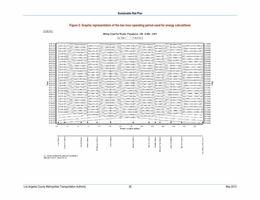
Sustainable Rail Plan
Los Angeles County Metropolitan Transportation Authority 38 May 2013
Figure 5: Graphic representation of the two hour operating period used for energy calculations

Sustainable Rail Scoping Plan
Los Angeles County Metropolitan Transportation Authority 39 May 2013
Table 14: Results of the simulated reference operation
Parameter Result Parameter Result
Total Train Count: 62 Line Filter kWh, Regen.: 7
Total Car Count: 124 Line Filter kWh, Motoring: 31 2
Total Train Miles: 770.6 Train kWh: 10979
Total Ton Miles: 92245 Net Train kWh: 9816
Electrical Train Miles: 709.3 Distribution kWh: 841
Total Car Miles: 1541.2 Distribution Losses: 7.1 %
Electrical Car Miles: 1418.6 Regen. Portion of Braking Energy: 19.1 %
Total Braking Energy: 6091 Regen. Contribution to System: 9.8 %
Rheostatic Brake kWh: 2751 Substation kWh/Car Mile: 7.51
Friction Brake kWh: 2171 Car kWh/Car Mile: 7.74

13-1
770
jl ©
2013
lac
mta
213.922.1100 Tel213.922.5259 Fax
metro.net
One Gateway Plaza Los Angeles, CA 90012-2952


