27
Sustainable refrigeration
Sustainable refrigeration
NCE/ 2
leading the way for Natural refrigerants
1986 – HCFC phase started across the Nestlé organisation
1997 – Nestlé take the leading role in reviving CO2 as an industrial
refrigerant
2001 – Ozone depleting substances reduced by 93% of finished goods
2001 – Commissioned the largest carbon dioxide/ammonia system to be
built in the last 50 years
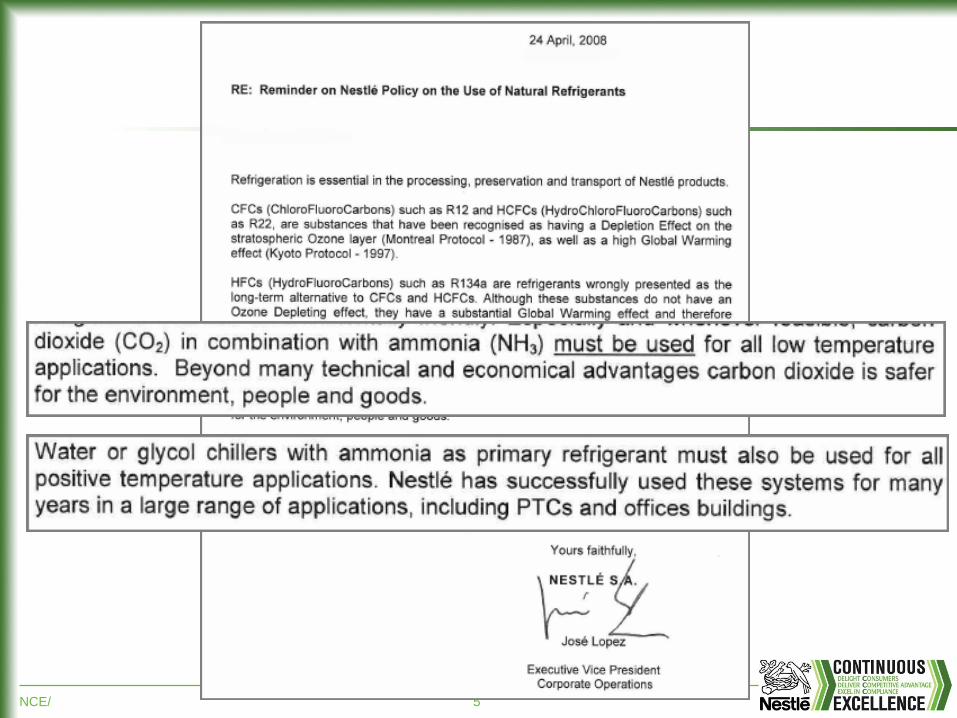
2001 - Nestlé position on refrigerants „where ever possible, nestle will use
natural refrigerants on new industrial refrigeration systems‟
NCE/ 3
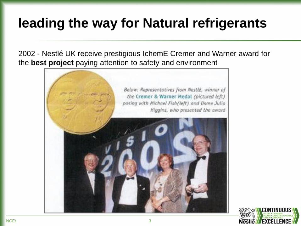
leading the way for Natural refrigerants
2002 - Nestlé UK receive prestigious IchemE Cremer and Warner award for
the best project paying attention to safety and environment
NCE/ 4
leading the way for Natural refrigerants
2005 – Nestlé set up working group on sustainable gases
Nestlé accelerate phase out of HydroChlroFlouroCarbons (HCFC‟s) well
ahead of the Montreal protocol and EU requirments. Approx 112 tons by
2004.
In most R22 phase out projects Nestlé has reduced energy by at least 25%
by using more efficient refrigeration systems. The indirect reduction of GWP
as a result is note worthy.
NCE/ 5
NCE/ 6
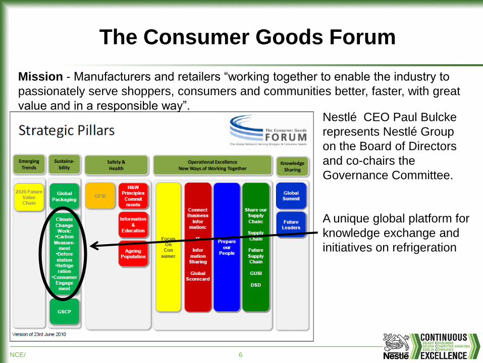
The Consumer Goods Forum
Mission - Manufacturers and retailers “working together to enable the industry to
passionately serve shoppers, consumers and communities better, faster, with great
value and in a responsible way”.
A unique global platform for
knowledge exchange and
initiatives on refrigeration
Nestlé CEO Paul Bulcke
represents Nestlé Group
on the Board of Directors
and co-chairs the
Governance Committee.
NCE/ 7
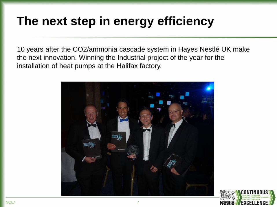
The next step in energy efficiency
10 years after the CO2/ammonia cascade system in Hayes Nestlé UK make
the next innovation. Winning the Industrial project of the year for the
installation of heat pumps at the Halifax factory.
NCE/ 8
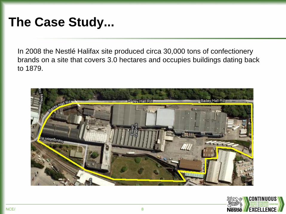
The Case Study...
In 2008 the Nestlé Halifax site produced circa 30,000 tons of confectionery
brands on a site that covers 3.0 hectares and occupies buildings dating back
to 1879.
NCE/ 9
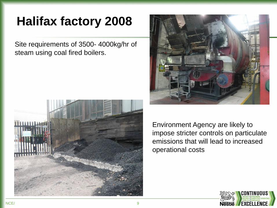
Halifax factory 2008
Site requirements of 3500- 4000kg/hr of
steam using coal fired boilers.
Environment Agency are likely to
impose stricter controls on particulate
emissions that will lead to increased
operational costs
NCE/ 10
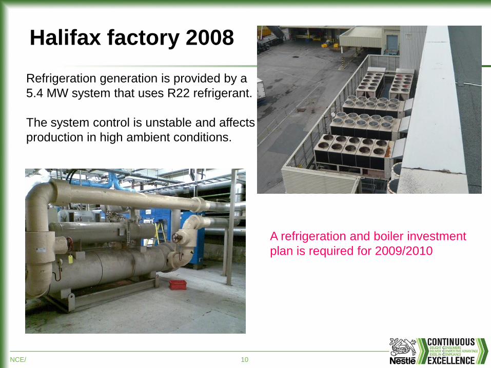
Halifax factory 2008
Refrigeration generation is provided by a
5.4 MW system that uses R22 refrigerant.
The system control is unstable and affects
production in high ambient conditions.
A refrigeration and boiler investment
plan is required for 2009/2010
NCE/ 11
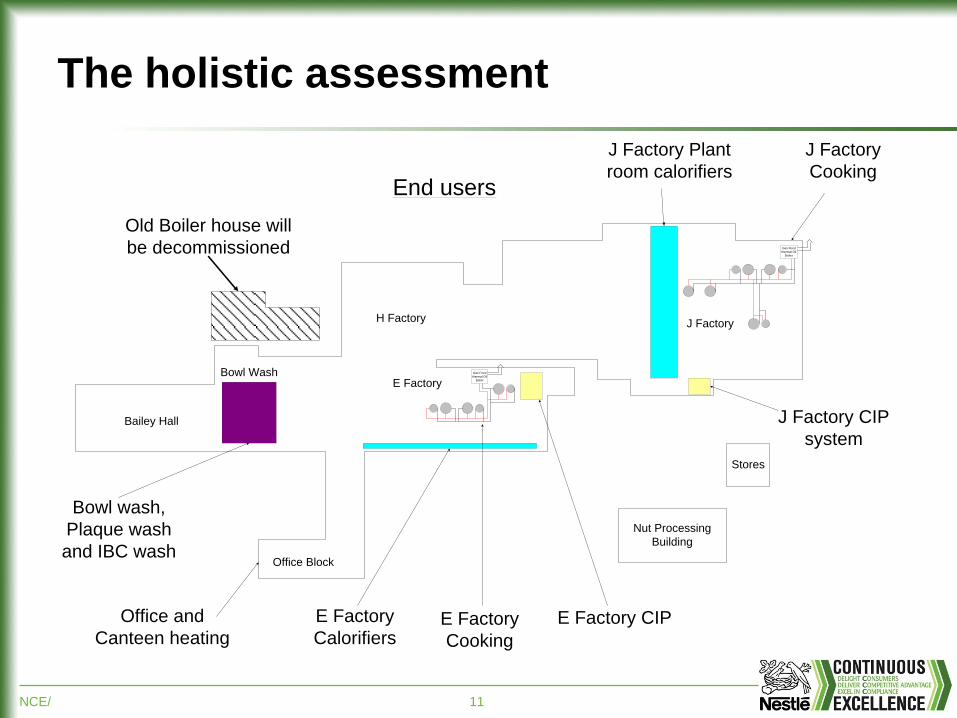
The holistic assessment
Office Block
Bailey Hall
E Factory
H FactoryJ Factory
Nut Processing
Building
Stores
End users
Bowl Wash
Old Boiler house will
be decommissioned Gas Fired
thermal Oil
Boiler
Gas Fired
thermal Oil
Boiler
J Factory Plant
room calorifiers
J Factory
Cooking
J Factory CIP
system
E Factory CIP E Factory
Cooking
E Factory
Calorifiers
Bowl wash,
Plaque wash
and IBC wash
Office and
Canteen heating
NCE/ 12
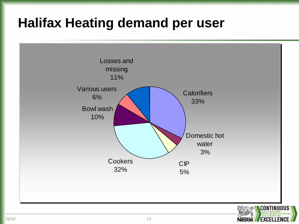
Halifax Heating demand per user
Calorifiers
33%
Domestic hot
water
3%
CIP
5%
Cookers
32%
Bowl wash
10%
Various users
6%
Losses and
missing
11%
NCE/ 13
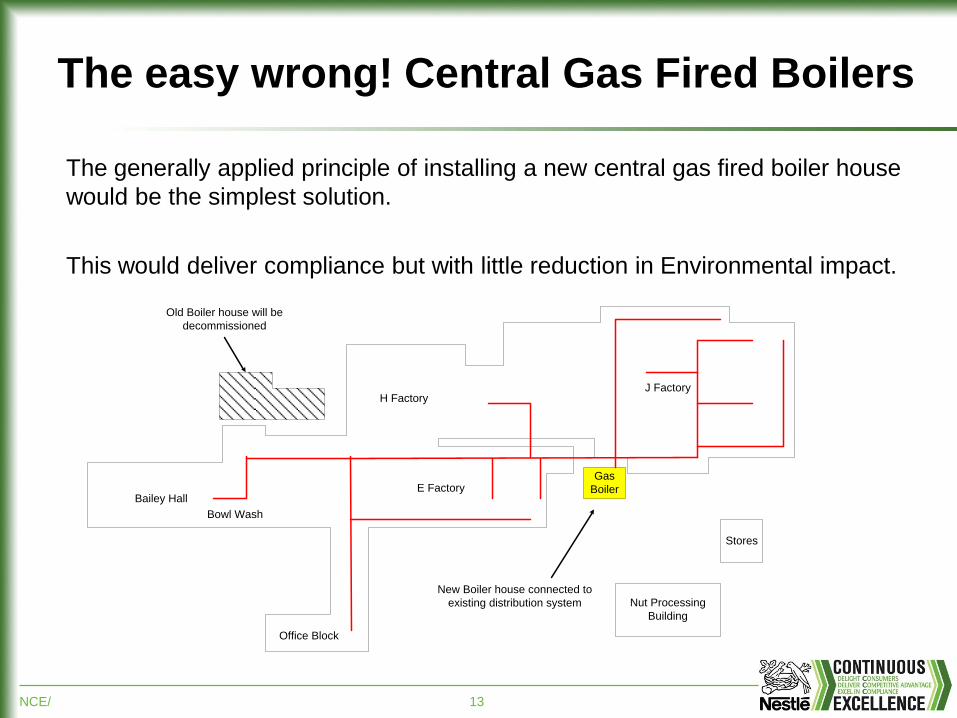
The easy wrong! Central Gas Fired Boilers
Office Block
Bailey HallE Factory
H FactoryJ Factory
Nut Processing
Building
Stores
Bowl Wash
Gas
Boiler
New Boiler house connected to
existing distribution system
Old Boiler house will be
decommissioned
The generally applied principle of installing a new central gas fired boiler house
would be the simplest solution.
This would deliver compliance but with little reduction in Environmental impact.
NCE/ 14
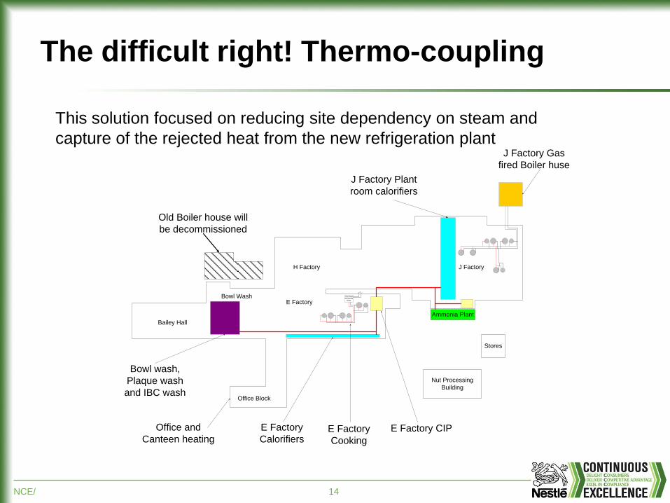
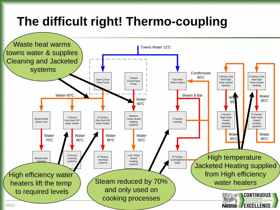
The difficult right! Thermo-coupling
Office Block
Bailey Hall
E Factory
H Factory J Factory
Nut Processing
Building
Stores
Bowl Wash
Old Boiler house will
be decommissioned
Gas Fired
thermal Oil
Boiler
J Factory Plant
room calorifiers
J Factory Gas
fired Boiler huse
E Factory CIP E Factory
Cooking
E Factory
Calorifiers
Bowl wash,
Plaque wash
and IBC wash
Office and
Canteen heating
Ammonia Plant
This solution focused on reducing site dependency on steam and
capture of the rejected heat from the new refrigeration plant
NCE/ 15
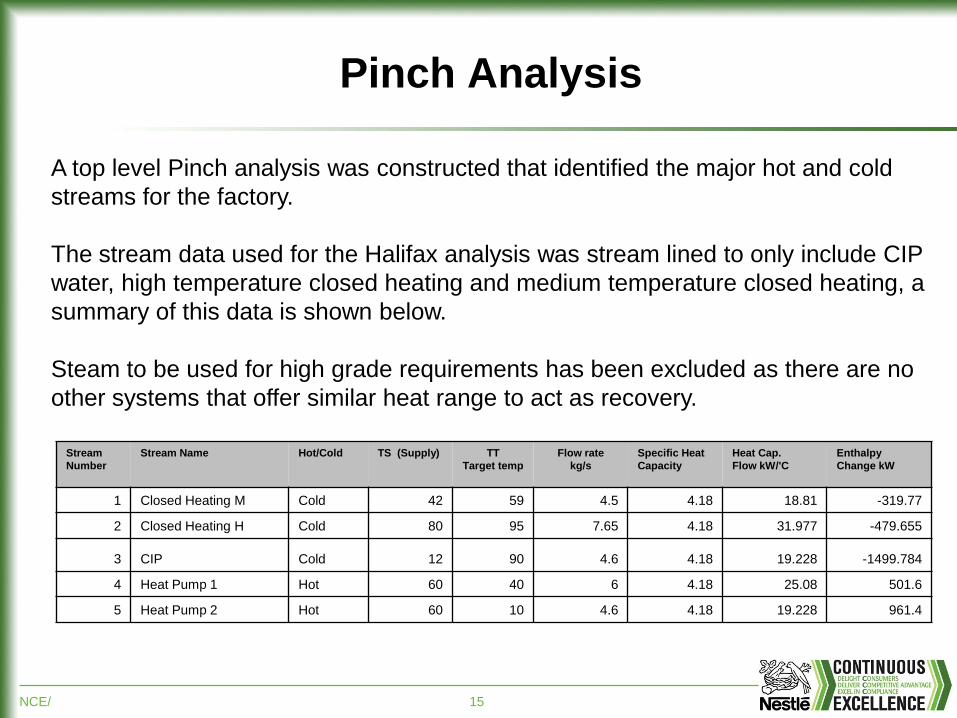
Pinch Analysis
A top level Pinch analysis was constructed that identified the major hot and cold
streams for the factory.
The stream data used for the Halifax analysis was stream lined to only include CIP
water, high temperature closed heating and medium temperature closed heating, a
summary of this data is shown below.
Steam to be used for high grade requirements has been excluded as there are no
other systems that offer similar heat range to act as recovery.
Stream
Number
Stream Name Hot/Cold TS (Supply) TT
Target temp
Flow rate
kg/s
Specific Heat
Capacity
Heat Cap.
Flow kW/'C
Enthalpy
Change kW
1 Closed Heating M Cold 42 59 4.5 4.18 18.81 -319.77
2 Closed Heating H Cold 80 95 7.65 4.18 31.977 -479.655
3 CIP Cold 12 90 4.6 4.18 19.228 -1499.784
4 Heat Pump 1 Hot 60 40 6 4.18 25.08 501.6
5 Heat Pump 2 Hot 60 10 4.6 4.18 19.228 961.4
NCE/ 16
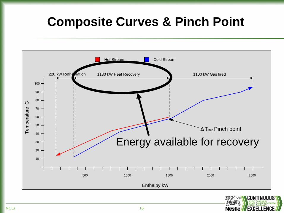
Composite Curves & Pinch Point
10
20
30
40
50
60
70
80
90
100
500 1000 1500 2000
Enthalpy kW
Te
mp
era
ture
„C
Cold StreamHot Stream
1130 kW Heat Recovery 1100 kW Gas fired 220 kW Refrigeration
2500
ΔTmin Pinch point
Energy available for recovery
NCE/ 17
The difficult right! Thermo-coupling
Mould Wash
Steam Coil
J Factory
Gas fired CIP
water heater
E Factory
Gas fired CIP
water heater
Medium
Temp closed
heating
systems
Mould wash
machine
J Factory
cleaning
systems
E Factory
cleaning
systems
Low Temp
closed
heating
systems
Open Circuit
Heat Pump
Closed
Circuit Heat
Pump
Gas fired
steam boilers
J Factory
cooking
E Factory
cooking/Bowl
wash
J factory Gas
fired high
temp closed
heating
E factory Gas
fired high
temp closed
heating
J Factory
High temp
closed
heating
systems
E Factory
High temp
closed
heating
systems
Towns Water 12'C
Water 60'C Steam 8 Bar Water
60'C
Water
70'C
Water
80'C
Water
80'C
Water
50'C
Water
95'C
Water
95'C
Water
85'C
Water
85'C
Condensate
90'C
Waste heat warms
towns water & supplies
Cleaning and Jacketed
systems
High efficiency water
heaters lift the temp
to required levels
Steam reduced by 70%
and only used on
cooking processes
High temperature
Jacketed Heating supplied
from High efficiency
water heaters
NCE/ 18
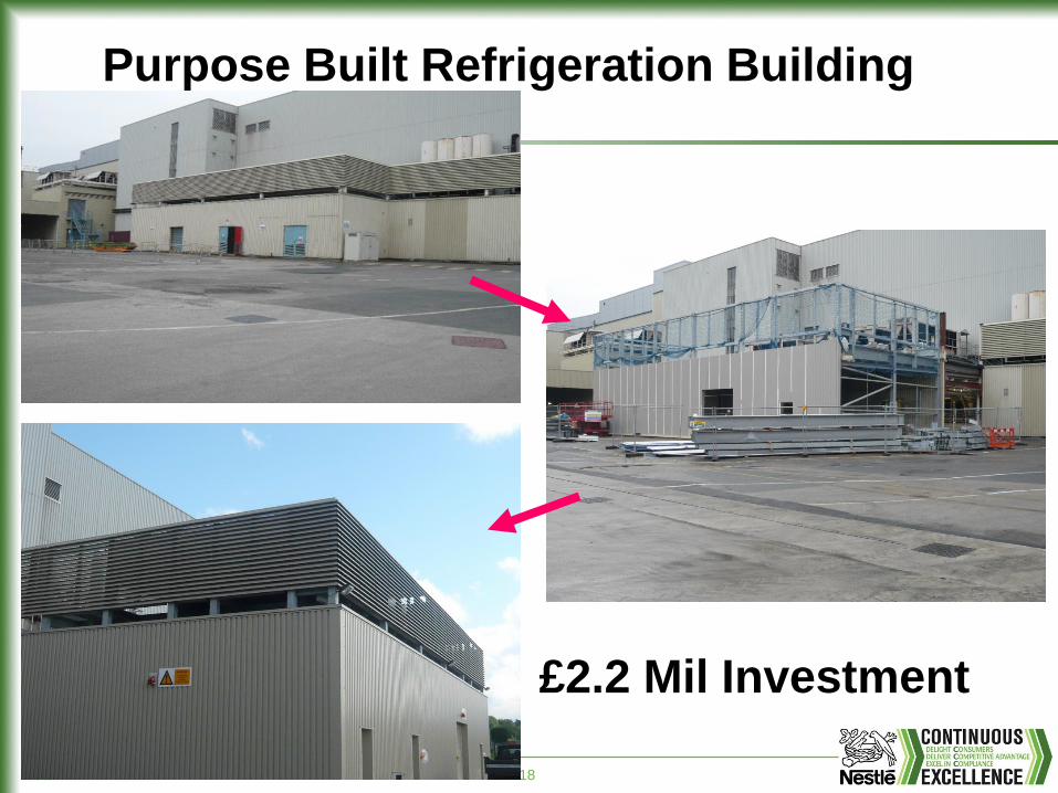
Purpose Built Refrigeration Building
£2.2 Mil Investment
NCE/ 19
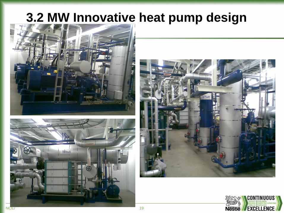
3.2 MW Innovative heat pump design
NCE/ 20
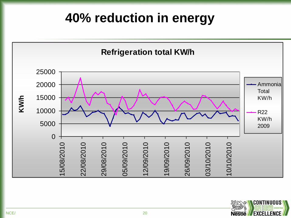
40% reduction in energy
Refrigeration total KW/h
0
5000
10000
15000
20000
25000
15
/08
/20
10
22
/08
/20
10
29
/08
/20
10
05
/09
/20
10
12
/09
/20
10
19
/09
/20
10
26
/09
/20
10
03
/10
/20
10
10
/10
/20
10
KW
/h
Ammonia
Total
KW/h
R22
KW/h
2009
NCE/ 21
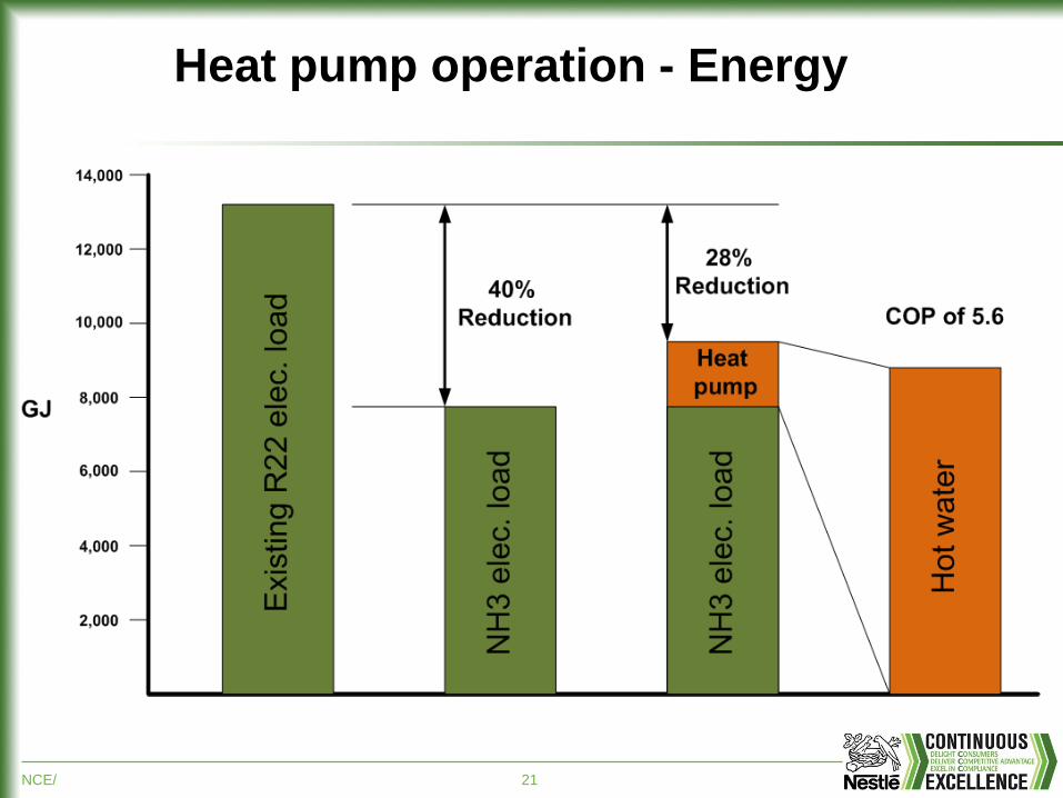
Heat pump operation - Energy
NCE/ 22
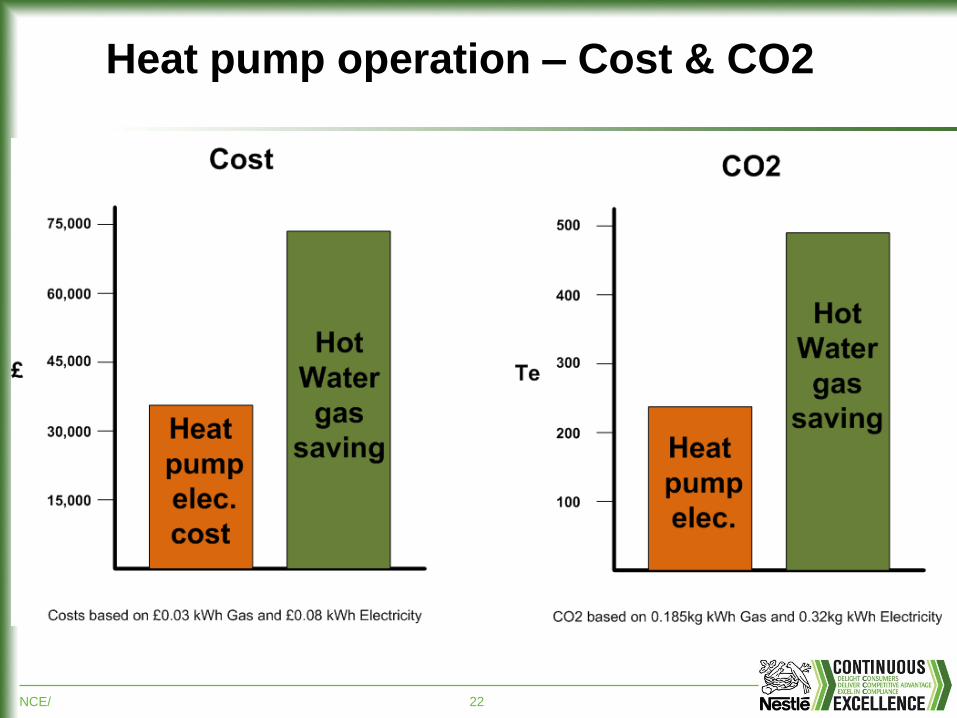
Heat pump operation – Cost & CO2
NCE/ 23
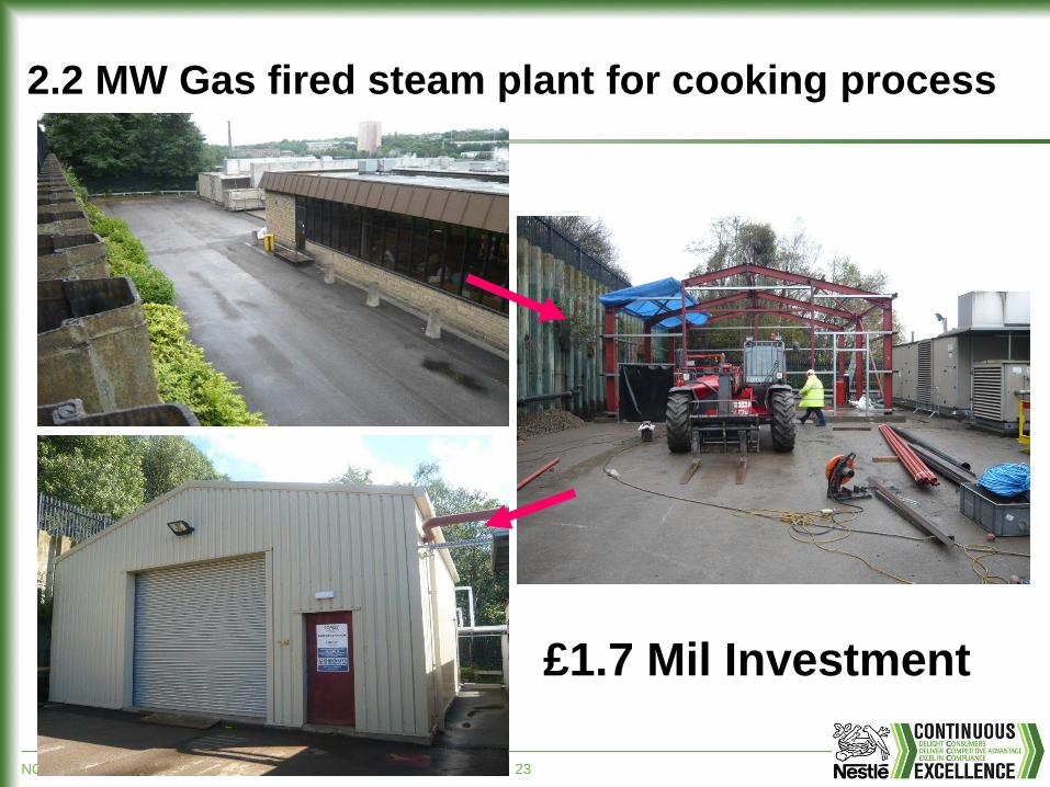
2.2 MW Gas fired steam plant for cooking process
£1.7 Mil Investment
NCE/ 24
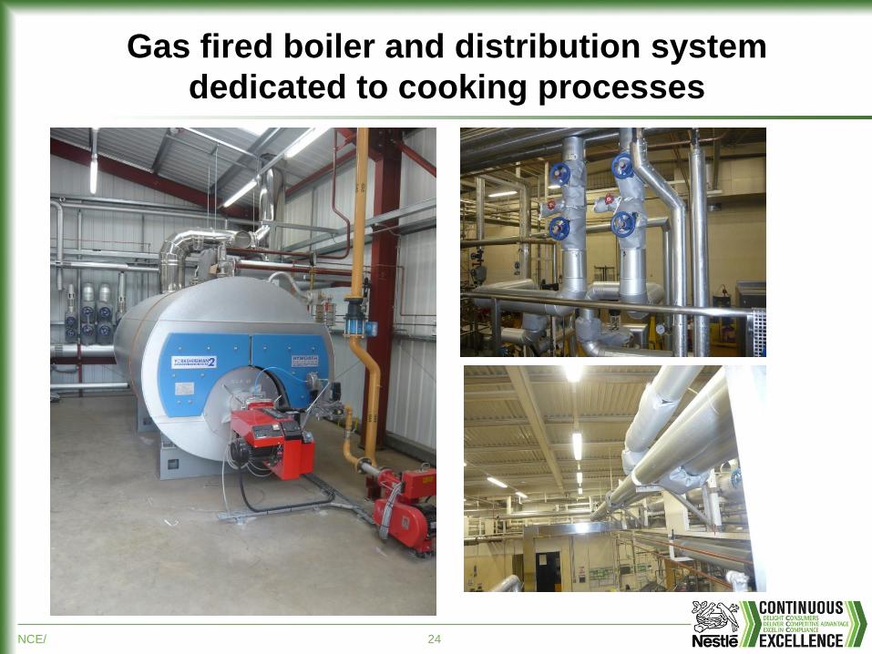
Gas fired boiler and distribution system
dedicated to cooking processes
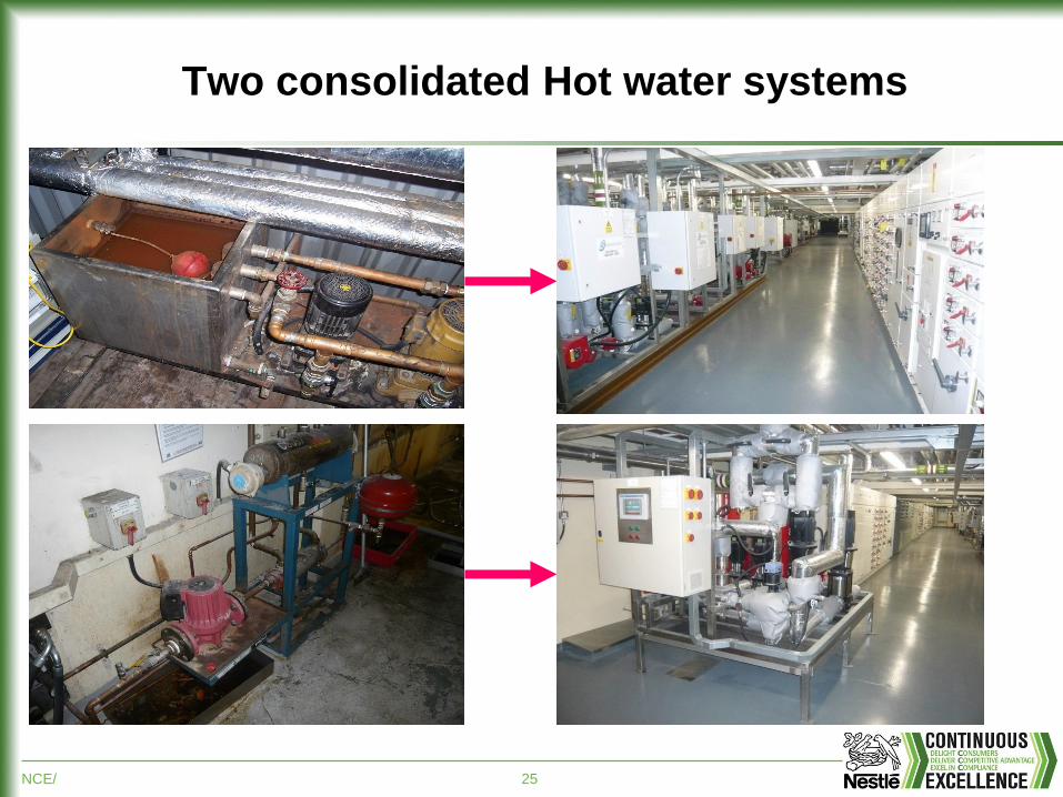
NCE/ 25
Two consolidated Hot water systems
NCE/ 26
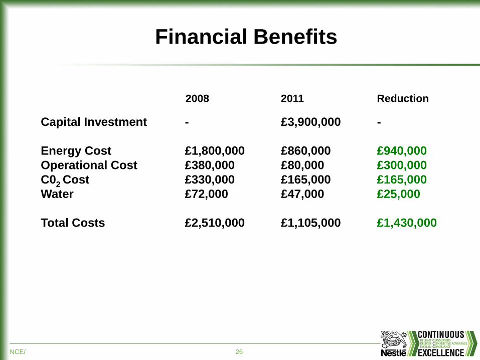
2008 2011 Reduction
Capital Investment - £3,900,000 -
Energy Cost £1,800,000 £860,000 £940,000
Operational Cost £380,000 £80,000 £300,000
C02 Cost £330,000 £165,000 £165,000
Water £72,000 £47,000 £25,000
Total Costs £2,510,000 £1,105,000 £1,430,000
Financial Benefits
NCE/ 27
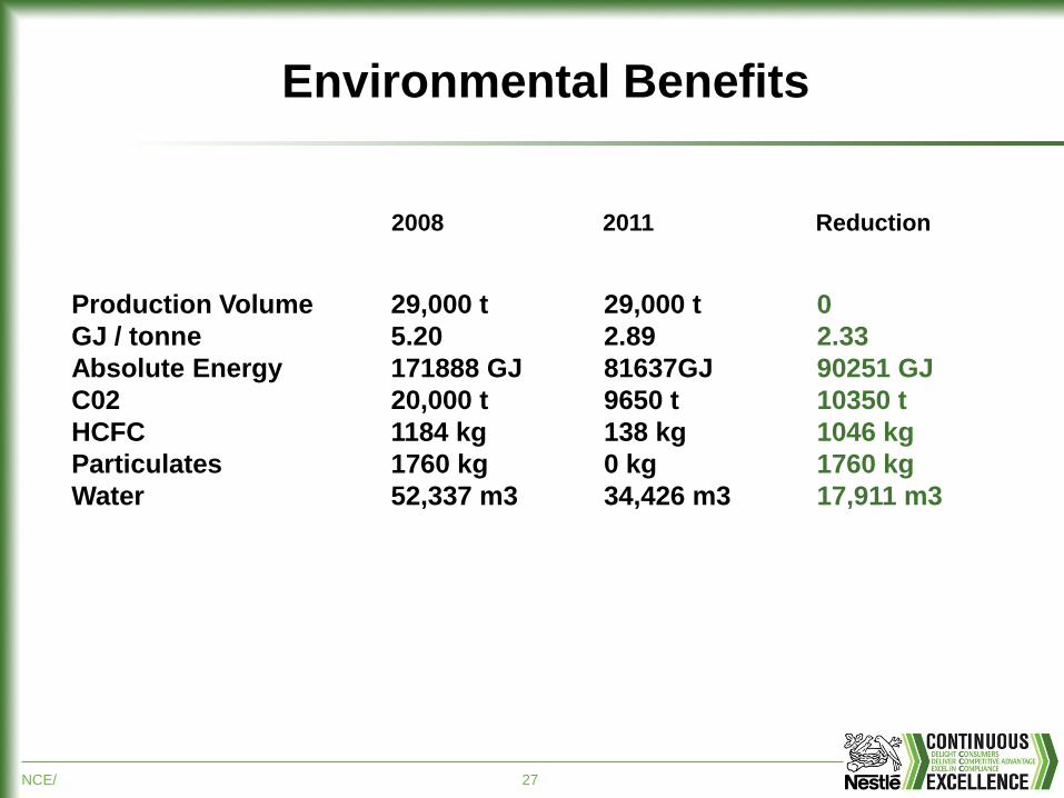
Environmental Benefits
Production Volume 29,000 t 29,000 t 0
GJ / tonne 5.20 2.89 2.33
Absolute Energy 171888 GJ 81637GJ 90251 GJ
C02 20,000 t 9650 t 10350 t
HCFC 1184 kg 138 kg 1046 kg
Particulates 1760 kg 0 kg 1760 kg
Water 52,337 m3 34,426 m3 17,911 m3
2008 2011 Reduction


