48
SIP Trunk Service Configuration Guide for IntelePeer NDA-31783 Issue 1.01 SV9300 ®
SIP Trunk Service Configuration Guidefor IntelePeer
NDA-31783Issue 1.01
SV9300®

NEC Corporation of America reserves the right to change the specifications, functions, or features atany time without notice.
NEC Corporation of America has prepared this document for use by its employees and customers.The information contained herein is the property of NEC Corporation of America and shall not bereproduced without prior written approval of NEC Corporation of America.
UNIVERGE is a registered trademark of NEC Corporation. All other brand names and product namesreferenced in this document are trademarks or registered trademarks of their respective companies.
Copyright 2016
NEC Corporation of America3929 W. John Carpenter Freeway
Irving, TX 75063-9406
Communications Technology Group

SIP Trunk Service Configuration Guide i
___________________________________________________________________________________
___________________________________________________________________________________
TABLE OF CONTENTS
Section 1 NEC SV9300 Setup Guide................................................................................... 1
1.1 This Guide and Related Documents .......................................................... 1
1.2 SIP Trunk Account Information .................................................................. 1
1.3 SV9300 System Software .......................................................................... 1
1.4 Requirements ............................................................................................ 2
1.5 Limitations ................................................................................................. 2
Section 2 NEC PBX Configuration...................................................................................... 3
2.1 Prerequisites .............................................................................................. 3
2.1.1 SIP Trunking Information from SIP trunk provider .................................... 3
2.1.2 NEC UNIVERGE SV9300 ......................................................................... 3
2.1.3 Installation Worksheet .............................................................................. 3
Section 3 SV9300 Programming ......................................................................................... 5
3.1 System Version and License Check .......................................................... 5
3.2 CC-CP00 Network Setup ........................................................................... 7
3.3 IP PAD Network Settings ......................................................................... 10
3.4 SIP Trunk Port Allocation ........................................................................ 11
3.5 SIP Trunk Port Settings ........................................................................... 12
3.6 SIP Trunk Route Settings ........................................................................ 14
3.7 Route to Route Connection Settings ....................................................... 17
3.8 SIP Trunk Control Channel Settings ........................................................ 18
3.9 SIP Trunk Destination Point Code Settings ............................................. 20
3.10 SIP Trunk Profile Settings ....................................................................... 21
3.11 T38 Fax Settings .................................................................................... 28
Issue 1.01 IntelePeer ___________________________________________________________________________________
ii Table of Contents
___________________________________________________________________________________
3.12 DID Digit Conversion Settings ................................................................. 30
3.13 Caller ID Display ...................................................................................... 33
Section 4 Initial Testing and Troubleshooting................................................................. 36
SIP Trunk Service Configuration Guide iii
___________________________________________________________________________________
___________________________________________________________________________________
LIST OF FIGURES and tables
Table 1 Installation Worksheet .......................................................................................... 4
Figure 1 System Version .................................................................................................... 5
Figure 2 CM F88 SIP Trunk Port Licenses ......................................................................... 6
Figure 3 CM 0B1xx Network Setup .................................................................................... 7
Figure 4 CM 0B1xx Network Setup (continued) ................................................................. 8
Figure 5 CM 0B2xx IP PAD Network Settings .................................................................. 10
Figure 6 CM 1003 SIP Trunk Port Allocation .................................................................... 11
Figure 7 CM 30 SIP Trunk Port Settings .......................................................................... 12
Figure 8 CM 30 SIP Trunk Port Settings (continued) ....................................................... 13
Figure 9 CM 35 SIP Trunk Route Settings ....................................................................... 14
Figure 10 CM 35 SIP Trunk Route Settings (continued) .................................................... 15
Figure 11 CM 35 SIP Trunk Route Settings (continued) .................................................... 15
Figure 12 CM 35 SIP Trunk Route Settings (continued) .................................................... 16
Figure 13 CM 36 Route to Route Connection Settings ...................................................... 17
Figure 14 CM A7 SIP Trunk Control Channel Settings ...................................................... 18
Figure 15 CM A7 SIP Trunk Control Channel Settings (continued) ................................... 19
Figure 16 CM A8 SIP Trunk Destination Point Code Settings ............................................ 20
Figure 17 CM BA SIP Trunk Profile Settings ...................................................................... 21
Figure 18 CM BA SIP Trunk Profile Settings (continued) ................................................... 22
Figure 19 CM BA SIP Trunk Profile Settings (continued) ................................................... 23
Figure 20 CM BA SIP Trunk Profile Settings (continued) ................................................... 24
Figure 21 CM BA SIP Trunk Profile Settings (continued) ................................................... 25
Issue 1.01 IntelePeer___________________________________________________________________________________
iv List of Figures and Tables
___________________________________________________________________________________
Figure 22 CM BA SIP Trunk Profile Settings (continued) ................................................... 26
Figure 23 CM 67 T38 Fax Settings ..................................................................................... 28
Figure 24 CM 6721 T38 Fax Settings (continued) .............................................................. 29
Figure 25 CM 35 YYY=170~172 DID Digit Conversion Settings ........................................ 30
Figure 26 CM 7690 DID Digit Conversion Settings (continued) ......................................... 31
Figure 27 CM 76 DID Digit Conversion Settings (continued) ............................................. 31
Figure 28 CM 08 Basic Services – Caller ID Display .......................................................... 33
Figure 29 CM 08 Basic Services – Caller ID Display (continued) ....................................... 33
Figure 30 CM 15 Service Restriction Class A – Caller ID Display (continued) ................... 34
Figure 31 CM 8A LCR Development Table – Caller ID Display (continued) ...................... 35
Table 2 Troubleshooting Guide ....................................................................................... 37
SIP Trunk Service Configuration Guide 1
Configuring NEC SV9300 for SIP Trunking
SECTION 1 NEC SV9300 SETUP GUIDE
1.1 This Guide and Related Documents
This guide was created to assist knowledgeable vendors with configuring the NEC SV9300 Communication Server and a SIP Trunking service. It provides sample entries for the required fields. The actual data is provided by your SIP trunk provider when service is activated. Questions about software and hardware installation or other PBX configuration issues should be directed to NEC’s National Technical Assistance Center (NTAC).
For complete details on using SIP trunks with the SV9300, refer to the SV9300 System Manual.
For complete details on using DID features, refer to the DID feature in the SV9300 Features and Specifications Manual.
For details about related hardware, refer to the SV9300 System Hardware Manual.
These manuals can be downloaded from NEC’s National Technical Assistance Center (NTAC) web site. You must have a valid dealer ID to access the documents.
1.2 SIP Trunk Account Information
Contact your SIP trunk provider representative.
1.3 SV9300 System Software
The SV9300 requires system software V3.1.0 or higher.
Issue 1.01 IntelePeer
2 SIP Trunk Service Configuration Guide
1.4 Requirements
With the SV9300, a VoIP gateway daughter board is required in addition to licensing for IP (SIP) trunks.
A minimum of four IP (SIP) trunks are required due to the NEC Communications Server infrastructure setup.
The system software for the NEC Communications Server should be version V3.1.0 or higher.
NEC recommends that the requirements and programming are completed with as much information as possible before scheduling an activation appointment with your SIP trunk provider.
1.5 Limitations
The following limitations apply:
UNIVERGE SV9300 supports T.38 or G.711 pass-through faxing. Supported fax protocol is determined by SIP trunk provider. If SIP trunk provider only supports best-effort, SIP trunk faxing may be unreliable.
SIP diversion header is not supported – Call forwarding to 8xx numbers
SIP Privacy – Cannot mark the calling party number as private or restricted
Secondary SIP server for failover is not supported
IntelePeer Issue 1.01
SIP Trunk Service Configuration Guide 3
SECTION 2 NEC PBX CONFIGURATION
This section provides information to NEC’s solution providers and NEC Associates for configuring an NEC UNIVERGE SV9300 to connect to a SIP Trunk service provider.
2.1 Prerequisites
Before you configure the UNIVERGE SV9300, you must have the following information available.
2.1.1 SIP Trunking Information from SIP trunk provider
Primary SIP Proxy Server IP Address and SIP account information.
Number Plan, if applicable for the Point-to-Point Connection
Trunking DID(s)The DID(s) are forwarded to the Public WAN IP address(s), DNS or DNS SRV records of the PBX.
2.1.2 NEC UNIVERGE SV9300
SV9300 CPU software version V2.4.1 or higher
VOIPDB (PZ-64IPLC-A, PZ-128IPLC-A, GPZ-64IPLD or GPZ-128IPLD)
SIP Trunk Port Licenses
Digital, IP and TDM Telephones
2.1.3 Installation Worksheet
Use the worksheet to record the information needed for setting up the SIP Trunking service.
Issue 1.01 IntelePeer
4 SIP Trunk Service Configuration Guide
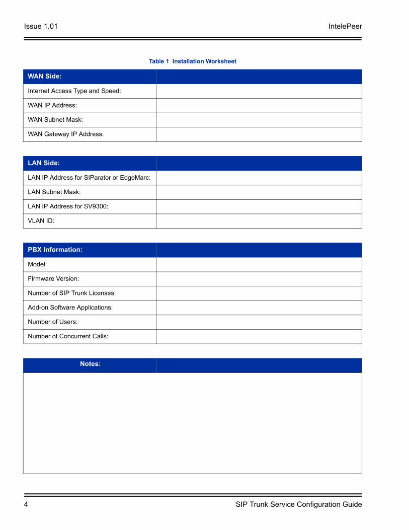
Table 1 Installation Worksheet
WAN Side:
Internet Access Type and Speed:
WAN IP Address:
WAN Subnet Mask:
WAN Gateway IP Address:
LAN Side:
LAN IP Address for SIParator or EdgeMarc:
LAN Subnet Mask:
LAN IP Address for SV9300:
VLAN ID:
PBX Information:
Model:
Firmware Version:
Number of SIP Trunk Licenses:
Add-on Software Applications:
Number of Users:
Number of Concurrent Calls:
Notes:
IntelePeer Issue 1.01
SIP Trunk Service Configuration Guide 5
SECTION 3 SV9300 PROGRAMMING
The following commands must be changed for SIP trunking service.
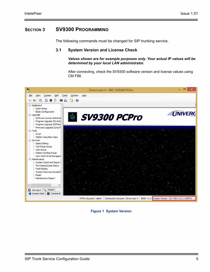
3.1 System Version and License Check
Values shown are for example purposes only. Your actual IP values will be determined by your local LAN administrator.
After connecting, check the SV9300 software version and license values using CM F88.
Figure 1 System Version
Issue 1.01 IntelePeer
6 SIP Trunk Service Configuration Guide
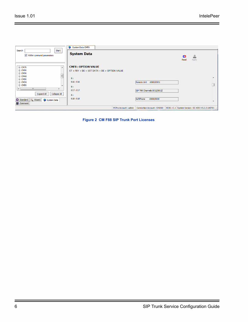
Figure 2 CM F88 SIP Trunk Port Licenses
IntelePeer Issue 1.01
SIP Trunk Service Configuration Guide 7
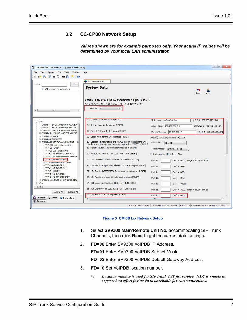
3.2 CC-CP00 Network Setup
Values shown are for example purposes only. Your actual IP values will be determined by your local LAN administrator.
1. Select SV9300 Main/Remote Unit No. accommodating SIP Trunk Channels, then click Read to get the current data settings.
2. FD=00 Enter SV9300 VoIPDB IP Address.
FD=01 Enter SV9300 VoIPDB Subnet Mask.
FD=02 Enter SV9300 VoIPDB Default Gateway Address.
3. FD=10 Set VoIPDB location number.
Location number is used for SIP trunk T.38 fax service. NEC is unable to support best effort faxing do to unreliable fax communications.
Figure 3 CM 0B1xx Network Setup
Issue 1.01 IntelePeer
8 SIP Trunk Service Configuration Guide
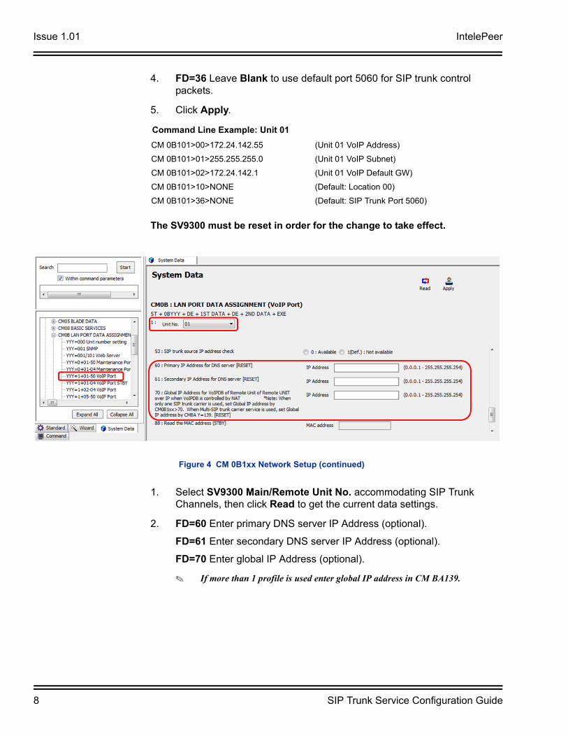
4. FD=36 Leave Blank to use default port 5060 for SIP trunk control packets.
5. Click Apply.
The SV9300 must be reset in order for the change to take effect.
1. Select SV9300 Main/Remote Unit No. accommodating SIP Trunk Channels, then click Read to get the current data settings.
2. FD=60 Enter primary DNS server IP Address (optional).
FD=61 Enter secondary DNS server IP Address (optional).
FD=70 Enter global IP Address (optional).
If more than 1 profile is used enter global IP address in CM BA139.
Command Line Example: Unit 01
CM 0B101>00>172.24.142.55 (Unit 01 VoIP Address)
CM 0B101>01>255.255.255.0 (Unit 01 VoIP Subnet)
CM 0B101>02>172.24.142.1 (Unit 01 VoIP Default GW)
CM 0B101>10>NONE (Default: Location 00)
CM 0B101>36>NONE (Default: SIP Trunk Port 5060)
Figure 4 CM 0B1xx Network Setup (continued)
IntelePeer Issue 1.01
SIP Trunk Service Configuration Guide 9
3. Click Apply.
The SV9300 must be reset in order for the change to take effect.
Command Line Example: Unit 01
CM 0B101>60>151.164.1.8 (Unit 01 Primary DNS Server Address)
CM 0B101>61>151.164.11.201 (Unit 01 Secondary DNS Server Address)
CM 0B101>02>172.24.142.1 (Unit 01 Global IP Address)
Issue 1.01 IntelePeer
10 SIP Trunk Service Configuration Guide
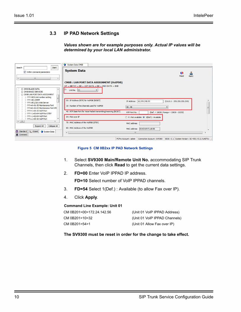
3.3 IP PAD Network Settings
Values shown are for example purposes only. Actual IP values will be determined by your local LAN administrator.
1. Select SV9300 Main/Remote Unit No. accommodating SIP Trunk Channels, then click Read to get the current data settings.
2. FD=00 Enter VoIP IPPAD IP address.
FD=10 Select number of VoIP IPPAD channels.
3. FD=54 Select 1(Def.) : Available (to allow Fax over IP).
4. Click Apply.
The SV9300 must be reset in order for the change to take effect.
Figure 5 CM 0B2xx IP PAD Network Settings
Command Line Example: Unit 01
CM 0B201>00>172.24.142.56 (Unit 01 VoIP IPPAD Address)
CM 0B201>10>32 (Unit 01 VoIP IPPAD Channels)
CM 0B201>54>1 (Unit 01 Allow Fax over IP)
IntelePeer Issue 1.01
SIP Trunk Service Configuration Guide 11
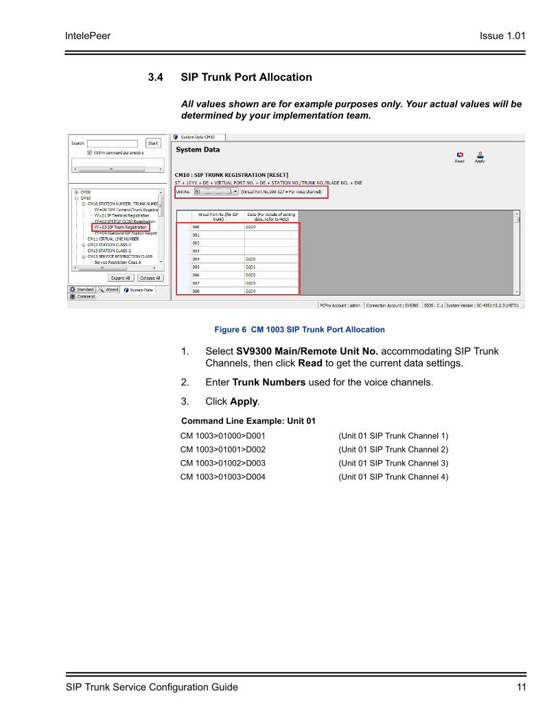
3.4 SIP Trunk Port Allocation
All values shown are for example purposes only. Your actual values will be determined by your implementation team.
1. Select SV9300 Main/Remote Unit No. accommodating SIP Trunk Channels, then click Read to get the current data settings.
2. Enter Trunk Numbers used for the voice channels.
3. Click Apply.
Figure 6 CM 1003 SIP Trunk Port Allocation
Command Line Example: Unit 01
CM 1003>01000>D001 (Unit 01 SIP Trunk Channel 1)
CM 1003>01001>D002 (Unit 01 SIP Trunk Channel 2)
CM 1003>01002>D003 (Unit 01 SIP Trunk Channel 3)
CM 1003>01003>D004 (Unit 01 SIP Trunk Channel 4)
Issue 1.01 IntelePeer
12 SIP Trunk Service Configuration Guide
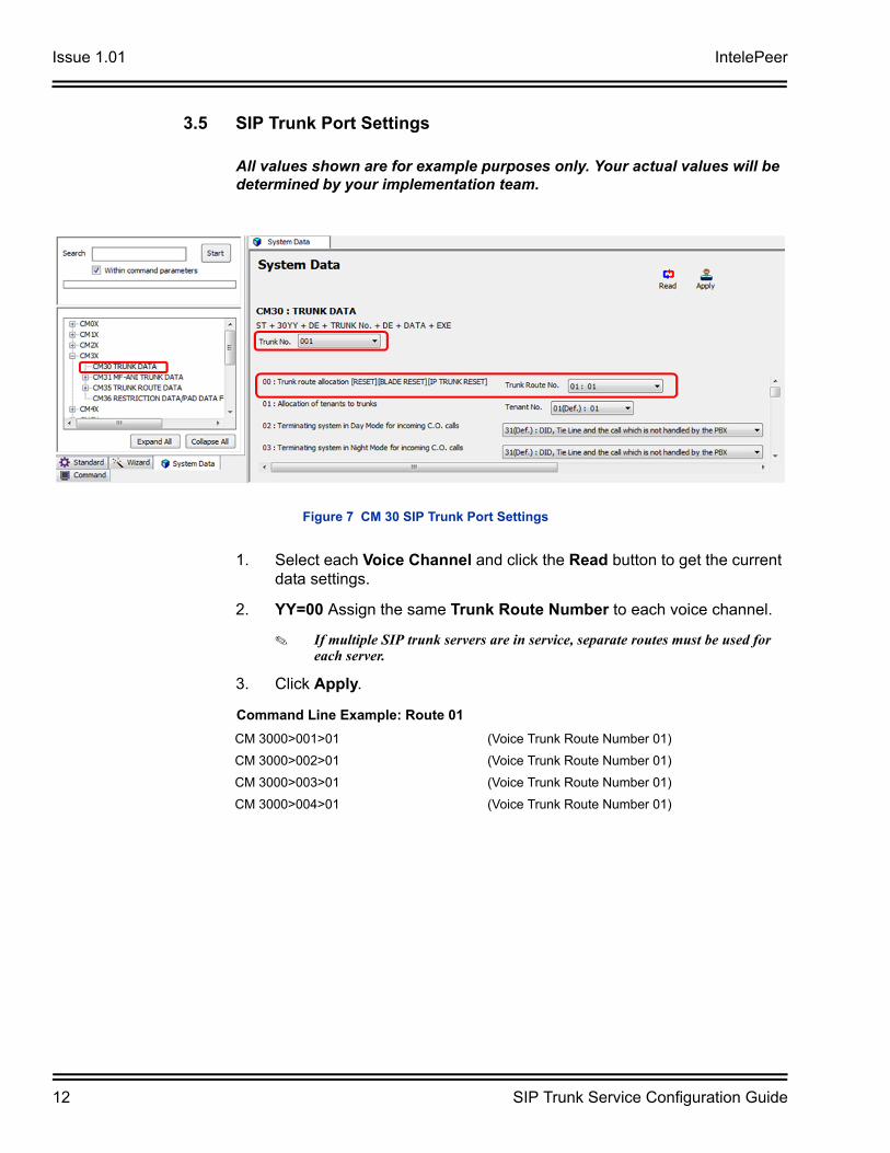
3.5 SIP Trunk Port Settings
All values shown are for example purposes only. Your actual values will be determined by your implementation team.
1. Select each Voice Channel and click the Read button to get the current data settings.
2. YY=00 Assign the same Trunk Route Number to each voice channel.
If multiple SIP trunk servers are in service, separate routes must be used for each server.
3. Click Apply.
Figure 7 CM 30 SIP Trunk Port Settings
Command Line Example: Route 01
CM 3000>001>01 (Voice Trunk Route Number 01)
CM 3000>002>01 (Voice Trunk Route Number 01)
CM 3000>003>01 (Voice Trunk Route Number 01)
CM 3000>004>01 (Voice Trunk Route Number 01)
IntelePeer Issue 1.01
SIP Trunk Service Configuration Guide 13
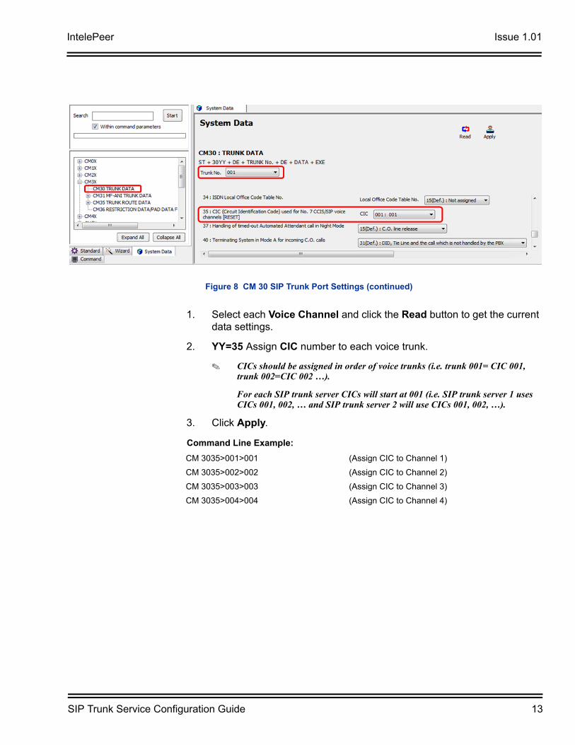
1. Select each Voice Channel and click the Read button to get the current data settings.
2. YY=35 Assign CIC number to each voice trunk.
CICs should be assigned in order of voice trunks (i.e. trunk 001= CIC 001, trunk 002=CIC 002 …).
For each SIP trunk server CICs will start at 001 (i.e. SIP trunk server 1 uses CICs 001, 002, … and SIP trunk server 2 will use CICs 001, 002, …).
3. Click Apply.
Figure 8 CM 30 SIP Trunk Port Settings (continued)
Command Line Example:
CM 3035>001>001 (Assign CIC to Channel 1)
CM 3035>002>002 (Assign CIC to Channel 2)
CM 3035>003>003 (Assign CIC to Channel 3)
CM 3035>004>004 (Assign CIC to Channel 4)
Issue 1.01 IntelePeer
14 SIP Trunk Service Configuration Guide
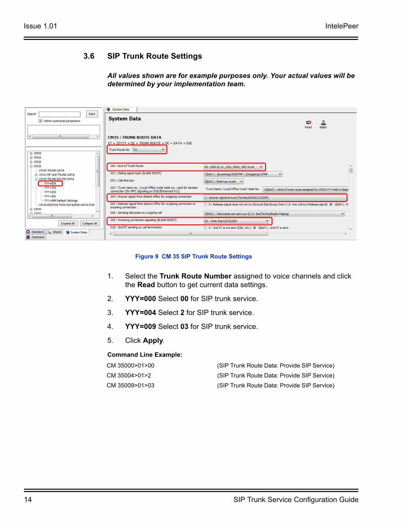
3.6 SIP Trunk Route Settings
All values shown are for example purposes only. Your actual values will be determined by your implementation team.
1. Select the Trunk Route Number assigned to voice channels and click the Read button to get current data settings.
2. YYY=000 Select 00 for SIP trunk service.
3. YYY=004 Select 2 for SIP trunk service.
4. YYY=009 Select 03 for SIP trunk service.
5. Click Apply.
Figure 9 CM 35 SIP Trunk Route Settings
Command Line Example:
CM 35000>01>00 (SIP Trunk Route Data: Provide SIP Service)
CM 35004>01>2 (SIP Trunk Route Data: Provide SIP Service)
CM 35009>01>03 (SIP Trunk Route Data: Provide SIP Service)
IntelePeer Issue 1.01
SIP Trunk Service Configuration Guide 15
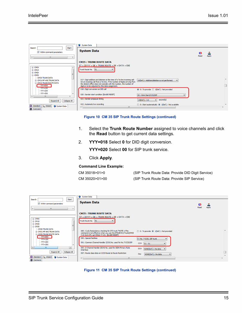
1. Select the Trunk Route Number assigned to voice channels and click the Read button to get current data settings.
2. YYY=018 Select 0 for DID digit conversion.
YYY=020 Select 00 for SIP trunk service.
3. Click Apply.
Figure 10 CM 35 SIP Trunk Route Settings (continued)
Command Line Example:
CM 35018>01>0 (SIP Trunk Route Data: Provide DID Digit Service)
CM 35020>01>00 (SIP Trunk Route Data: Provide SIP Service)
Figure 11 CM 35 SIP Trunk Route Settings (continued)
Issue 1.01 IntelePeer
16 SIP Trunk Service Configuration Guide
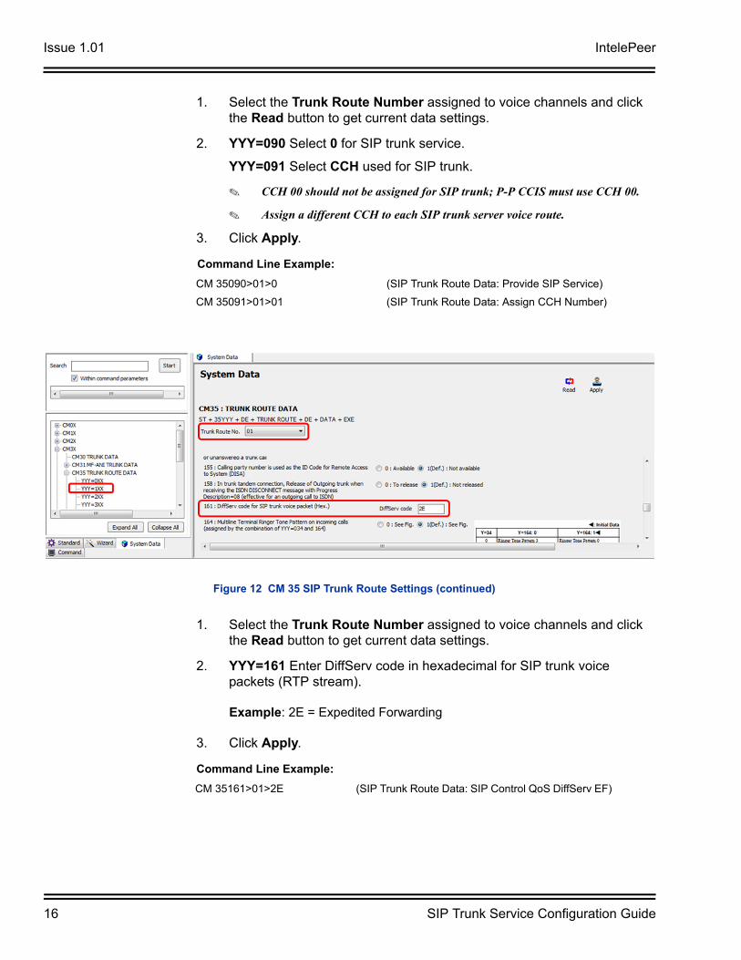
1. Select the Trunk Route Number assigned to voice channels and click the Read button to get current data settings.
2. YYY=090 Select 0 for SIP trunk service.
YYY=091 Select CCH used for SIP trunk.
CCH 00 should not be assigned for SIP trunk; P-P CCIS must use CCH 00.
Assign a different CCH to each SIP trunk server voice route.
3. Click Apply.
1. Select the Trunk Route Number assigned to voice channels and click the Read button to get current data settings.
2. YYY=161 Enter DiffServ code in hexadecimal for SIP trunk voice packets (RTP stream).
Example: 2E = Expedited Forwarding
3. Click Apply.
Command Line Example:
CM 35090>01>0 (SIP Trunk Route Data: Provide SIP Service)
CM 35091>01>01 (SIP Trunk Route Data: Assign CCH Number)
Figure 12 CM 35 SIP Trunk Route Settings (continued)
Command Line Example:
CM 35161>01>2E (SIP Trunk Route Data: SIP Control QoS DiffServ EF)
IntelePeer Issue 1.01
SIP Trunk Service Configuration Guide 17
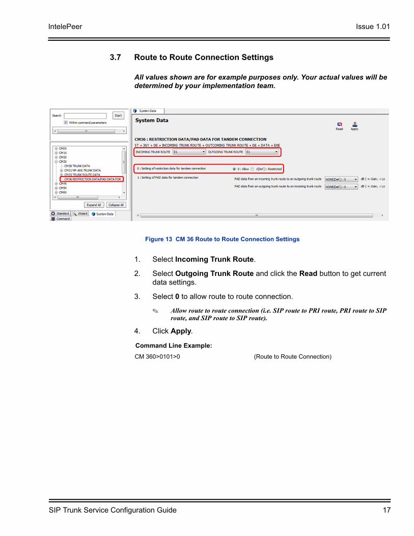
3.7 Route to Route Connection Settings
All values shown are for example purposes only. Your actual values will be determined by your implementation team.
1. Select Incoming Trunk Route.
2. Select Outgoing Trunk Route and click the Read button to get current data settings.
3. Select 0 to allow route to route connection.
Allow route to route connection (i.e. SIP route to PRI route, PRI route to SIP route, and SIP route to SIP route).
4. Click Apply.
Figure 13 CM 36 Route to Route Connection Settings
Command Line Example:
CM 360>0101>0 (Route to Route Connection)
Issue 1.01 IntelePeer
18 SIP Trunk Service Configuration Guide
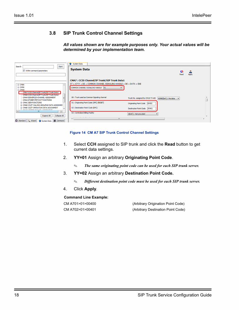
3.8 SIP Trunk Control Channel Settings
All values shown are for example purposes only. Your actual values will be determined by your implementation team.
1. Select CCH assigned to SIP trunk and click the Read button to get current data settings.
2. YY=01 Assign an arbitrary Originating Point Code.
The same originating point code can be used for each SIP trunk server.
3. YY=02 Assign an arbitrary Destination Point Code.
Different destination point code must be used for each SIP trunk server.
4. Click Apply.
Figure 14 CM A7 SIP Trunk Control Channel Settings
Command Line Example:
CM A701>01>00400 (Arbitrary Origination Point Code)
CM A702>01>00401 (Arbitrary Destination Point Code)
IntelePeer Issue 1.01
SIP Trunk Service Configuration Guide 19
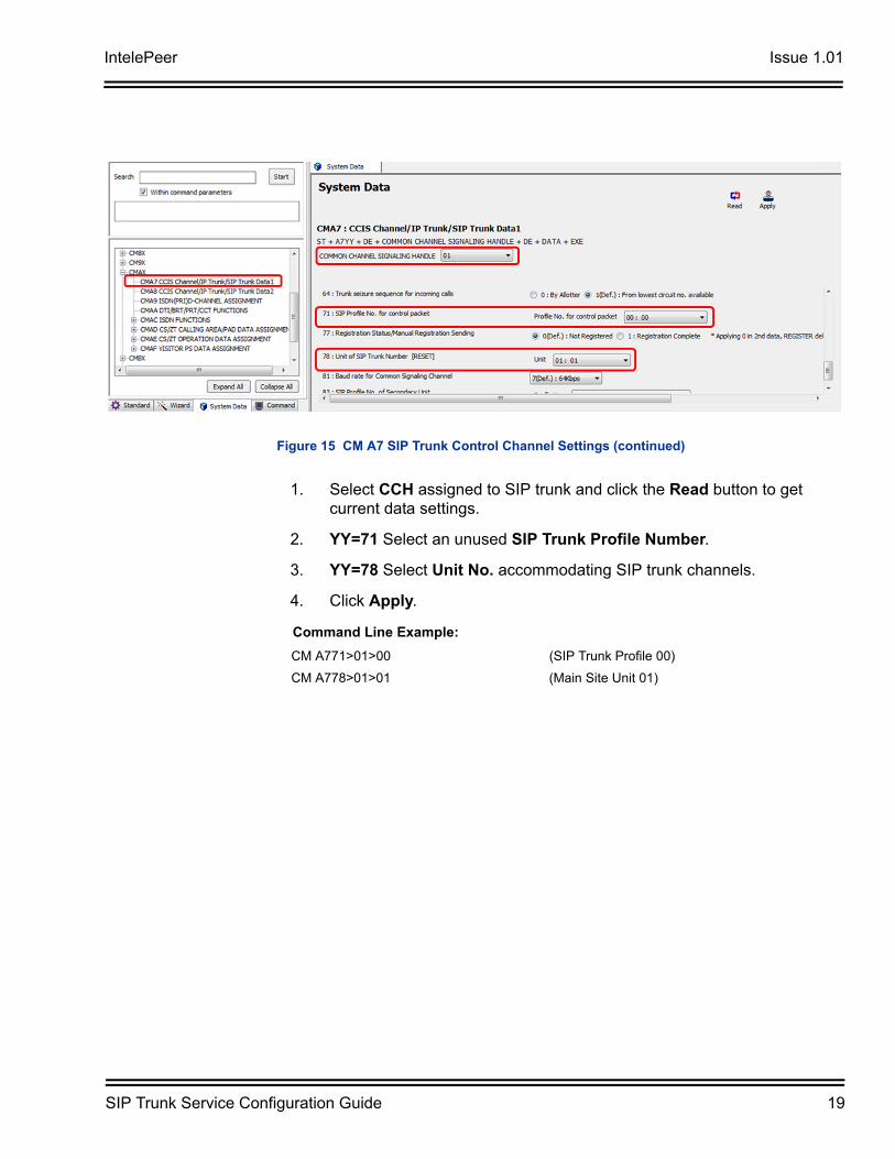
1. Select CCH assigned to SIP trunk and click the Read button to get current data settings.
2. YY=71 Select an unused SIP Trunk Profile Number.
3. YY=78 Select Unit No. accommodating SIP trunk channels.
4. Click Apply.
Figure 15 CM A7 SIP Trunk Control Channel Settings (continued)
Command Line Example:
CM A771>01>00 (SIP Trunk Profile 00)
CM A778>01>01 (Main Site Unit 01)
Issue 1.01 IntelePeer
20 SIP Trunk Service Configuration Guide
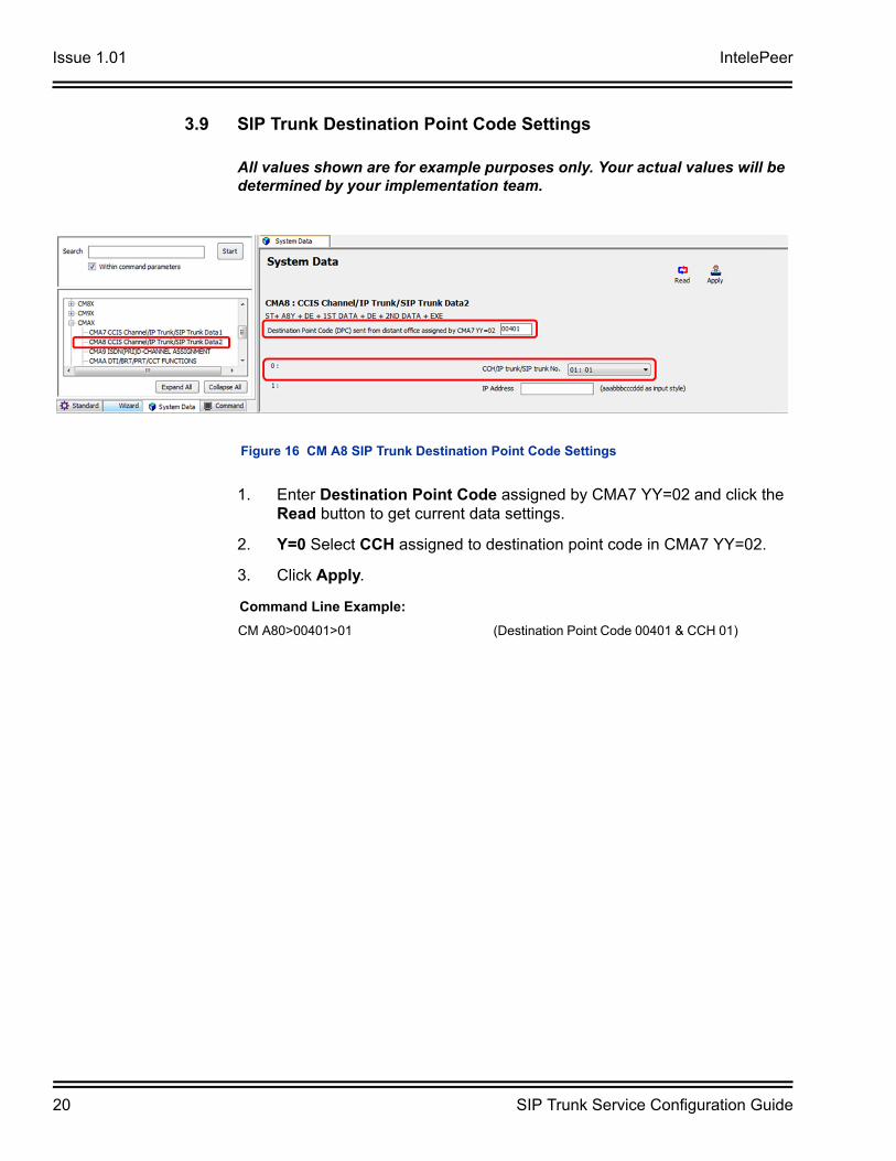
3.9 SIP Trunk Destination Point Code Settings
All values shown are for example purposes only. Your actual values will be determined by your implementation team.
1. Enter Destination Point Code assigned by CMA7 YY=02 and click the Read button to get current data settings.
2. Y=0 Select CCH assigned to destination point code in CMA7 YY=02.
3. Click Apply.
Figure 16 CM A8 SIP Trunk Destination Point Code Settings
Command Line Example:
CM A80>00401>01 (Destination Point Code 00401 & CCH 01)
IntelePeer Issue 1.01
SIP Trunk Service Configuration Guide 21
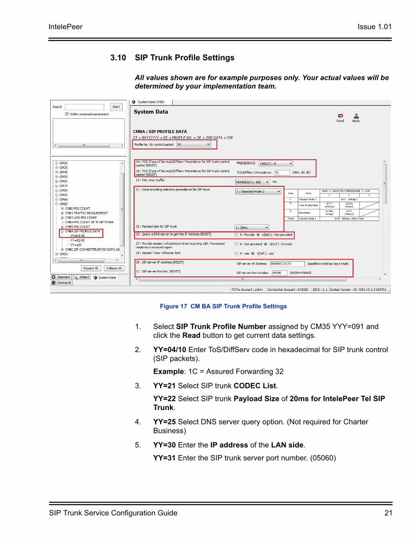
3.10 SIP Trunk Profile Settings
All values shown are for example purposes only. Your actual values will be determined by your implementation team.
1. Select SIP Trunk Profile Number assigned by CM35 YYY=091 and click the Read button to get current data settings.
2. YY=04/10 Enter ToS/DiffServ code in hexadecimal for SIP trunk control (SIP packets).
Example: 1C = Assured Forwarding 32
3. YY=21 Select SIP trunk CODEC List.
YY=22 Select SIP trunk Payload Size of 20ms for IntelePeer Tel SIP Trunk.
4. YY=25 Select DNS server query option. (Not required for Charter Business)
5. YY=30 Enter the IP address of the LAN side.
YY=31 Enter the SIP trunk server port number. (05060)
Figure 17 CM BA SIP Trunk Profile Settings
Issue 1.01 IntelePeer
22 SIP Trunk Service Configuration Guide
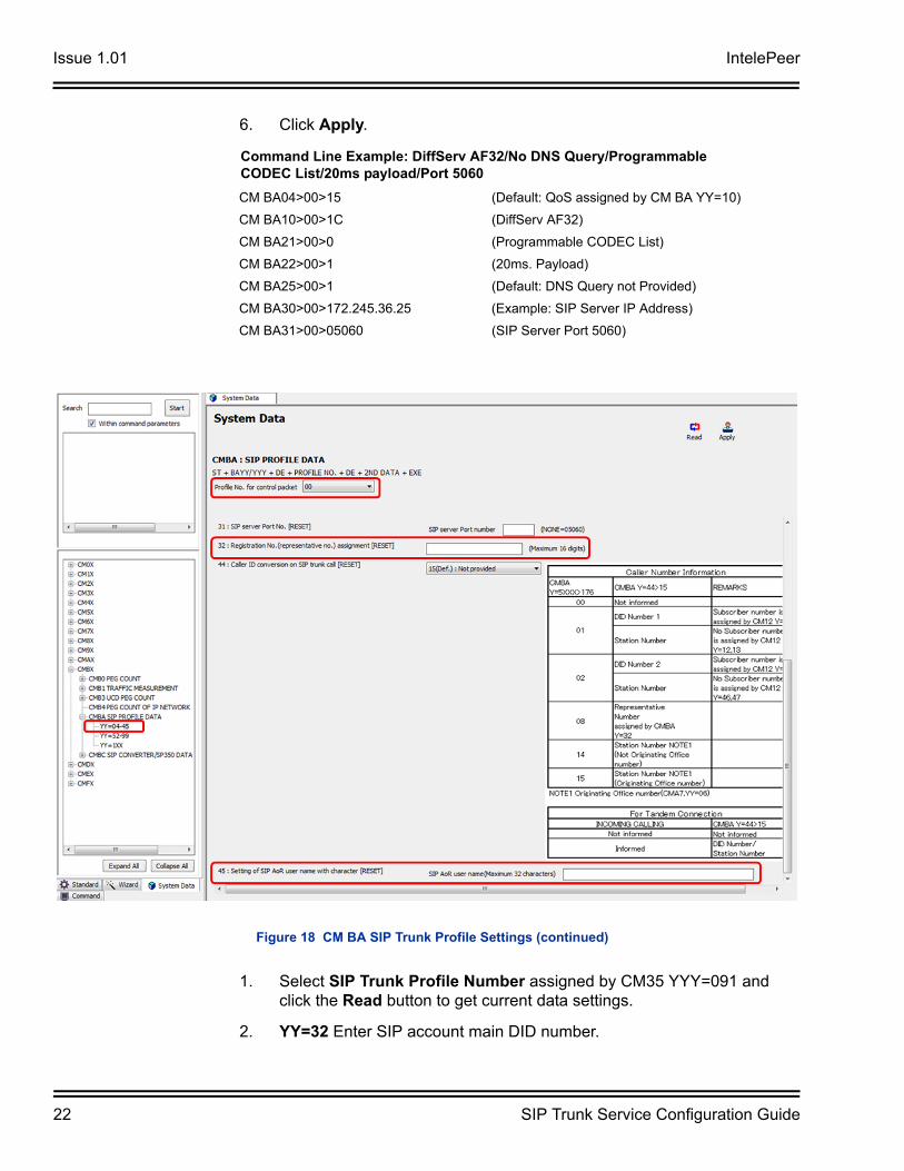
6. Click Apply.
1. Select SIP Trunk Profile Number assigned by CM35 YYY=091 and click the Read button to get current data settings.
2. YY=32 Enter SIP account main DID number.
Command Line Example: DiffServ AF32/No DNS Query/Programmable CODEC List/20ms payload/Port 5060
CM BA04>00>15 (Default: QoS assigned by CM BA YY=10)
CM BA10>00>1C (DiffServ AF32)
CM BA21>00>0 (Programmable CODEC List)
CM BA22>00>1 (20ms. Payload)
CM BA25>00>1 (Default: DNS Query not Provided)
CM BA30>00>172.245.36.25 (Example: SIP Server IP Address)
CM BA31>00>05060 (SIP Server Port 5060)
Figure 18 CM BA SIP Trunk Profile Settings (continued)
IntelePeer Issue 1.01
SIP Trunk Service Configuration Guide 23
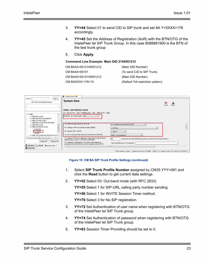
3. YY=44 Select 01 to send CID to SIP trunk and set 8A Y=5XXX>176 accordingly.
4. YY=45 Set the Address of Registration (AoR) with the BTN/OTG of the IntelePeer tel SIP Trunk Group. In this case 8088881900 is the BTN of the test trunk group
5. Click Apply.
1. Select SIP Trunk Profile Number assigned by CM35 YYY=091 and click the Read button to get current data settings.
2. YY=52 Select 03: Out-band mode (with RFC 2833)
YY=55 Select 1 for SIP-URL calling party number sending.
YY=56 Select 1 for INVITE Session Timer method.
YY=70 Select 3 for No SIP registration.
3. YY=72 Set Authentication of user name when registering with BTN/OTG of the IntelePeer tel SIP Trunk group.
4. YY=74 Set Authentication of password when registering with BTN/OTG of the IntelePeer tel SIP Trunk group.
5. YY=83 Session Timer Providing should be set to 0.
Command Line Example: Main DID 2145551212
CM BA32>00>2145551212 (Main DID Number)
CM BA44>00>01 (To send CID to SIP Trunk)
CM BA45>00>2145551212 (Main DID Number)
CM 8A5XXX>176>15 (Default Toll restriction pattern)
Figure 19 CM BA SIP Trunk Profile Settings (continued)
Issue 1.01 IntelePeer
24 SIP Trunk Service Configuration Guide
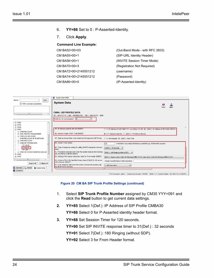
6. YY=86 Set to 0 : P-Asserted-Identity.
7. Click Apply.
1. Select SIP Trunk Profile Number assigned by CM35 YYY=091 and click the Read button to get current data settings.
2. YY=85 Select 1(Def.) :IP Address of SIP Profile CMBA30
YY=86 Select 0 for P-Asserted identity header format.
3. YY=88 Set Session Timer for 120 seconds.
YY=90 Set SIP INVITE response timer to 31(Def.) : 32 seconds
YY=91 Select 7(Def.) :180 Ringing (without SDP).
YY=92 Select 3 for From Header format.
Command Line Example:
CM BA52>00>03 (Out-Band Mode - with RFC 2833)
CM BA55>00>1 (SIP-URL Identity Header)
CM BA56>00>1 (INVITE Session Timer Mode)
CM BA70>00>3 (Registration Not Required)
CM BA72>00>2145551212 (username)
CM BA74>00>2145551212 (Password)
CM BA86>00>0 (IP-Asserted-Identity)
Figure 20 CM BA SIP Trunk Profile Settings (continued)
IntelePeer Issue 1.01
SIP Trunk Service Configuration Guide 25
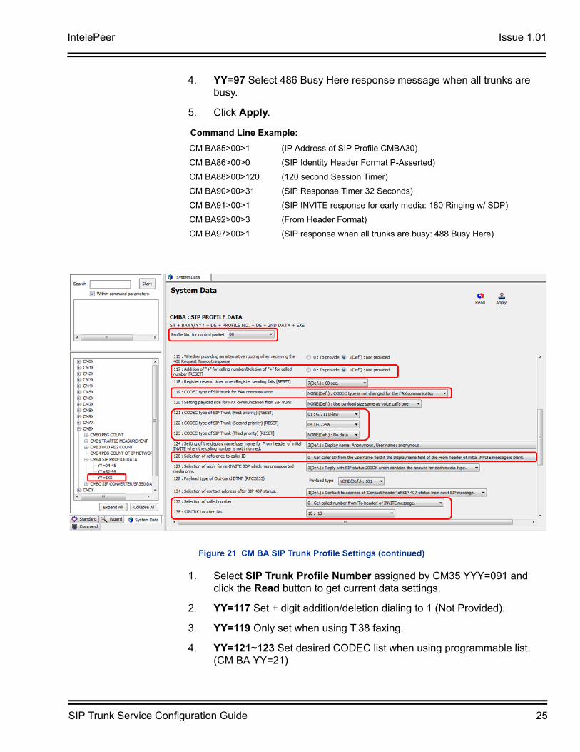
4. YY=97 Select 486 Busy Here response message when all trunks are busy.
5. Click Apply.
1. Select SIP Trunk Profile Number assigned by CM35 YYY=091 and click the Read button to get current data settings.
2. YY=117 Set + digit addition/deletion dialing to 1 (Not Provided).
3. YY=119 Only set when using T.38 faxing.
4. YY=121~123 Set desired CODEC list when using programmable list. (CM BA YY=21)
Command Line Example:
CM BA85>00>1 (IP Address of SIP Profile CMBA30)
CM BA86>00>0 (SIP Identity Header Format P-Asserted)
CM BA88>00>120 (120 second Session Timer)
CM BA90>00>31 (SIP Response Timer 32 Seconds)
CM BA91>00>1 (SIP INVITE response for early media: 180 Ringing w/ SDP)
CM BA92>00>3 (From Header Format)
CM BA97>00>1 (SIP response when all trunks are busy: 488 Busy Here)
Figure 21 CM BA SIP Trunk Profile Settings (continued)
Issue 1.01 IntelePeer
26 SIP Trunk Service Configuration Guide
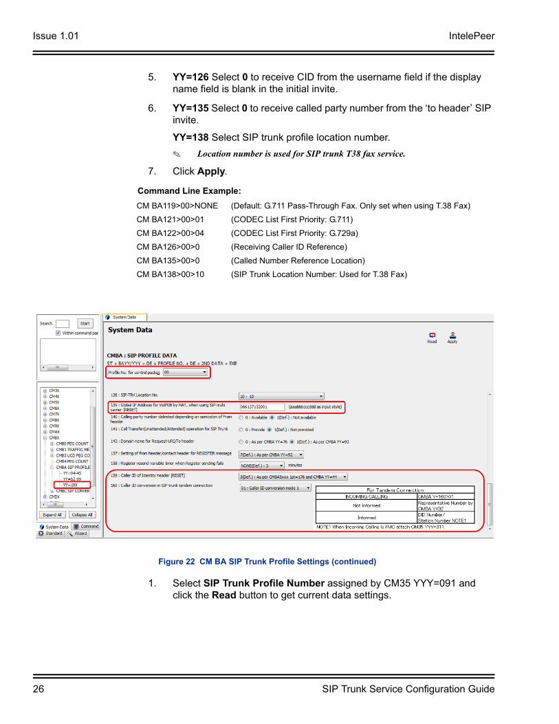
5. YY=126 Select 0 to receive CID from the username field if the display name field is blank in the initial invite.
6. YY=135 Select 0 to receive called party number from the ‘to header’ SIP invite.
YY=138 Select SIP trunk profile location number.
Location number is used for SIP trunk T38 fax service.
7. Click Apply.
1. Select SIP Trunk Profile Number assigned by CM35 YYY=091 and click the Read button to get current data settings.
Command Line Example:
CM BA119>00>NONE (Default: G.711 Pass-Through Fax. Only set when using T.38 Fax)
CM BA121>00>01 (CODEC List First Priority: G.711)
CM BA122>00>04 (CODEC List First Priority: G.729a)
CM BA126>00>0 (Receiving Caller ID Reference)
CM BA135>00>0 (Called Number Reference Location)
CM BA138>00>10 (SIP Trunk Location Number: Used for T.38 Fax)
Figure 22 CM BA SIP Trunk Profile Settings (continued)
IntelePeer Issue 1.01
SIP Trunk Service Configuration Guide 27
2. YY=139 Enter global IP address when more than 1 SIP trunk profile is used.
If only one SIP trunk profile is used, enter global IP Address in CM0B YY=101>70.
3. YY=159 Select identity header caller ID selection.
4. YY=160 Select Caller ID format for SIP trunk tandem connection.
5. Click Apply.
Command Line Example:
CM BA139>00>066137132001 (Global IP Address)
CM BA159>00>3 (Default: Calling Party Number Sending Option)
CM BA160>00>01 (Tandem Conversion Mode 1)
Issue 1.01 IntelePeer
28 SIP Trunk Service Configuration Guide
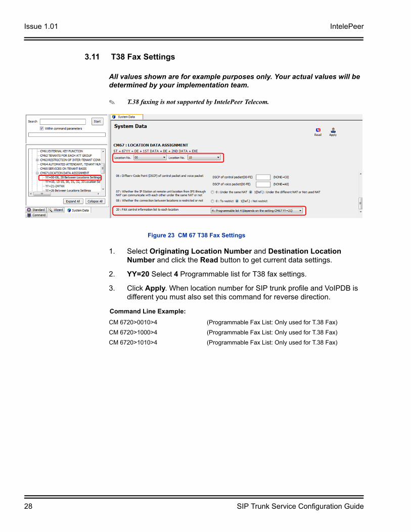
3.11 T38 Fax Settings
All values shown are for example purposes only. Your actual values will be determined by your implementation team.
T.38 faxing is not supported by IntelePeer Telecom.
1. Select Originating Location Number and Destination Location Number and click the Read button to get current data settings.
2. YY=20 Select 4 Programmable list for T38 fax settings.
3. Click Apply. When location number for SIP trunk profile and VoIPDB is different you must also set this command for reverse direction.
Figure 23 CM 67 T38 Fax Settings
Command Line Example:
CM 6720>0010>4 (Programmable Fax List: Only used for T.38 Fax)
CM 6720>1000>4 (Programmable Fax List: Only used for T.38 Fax)
CM 6720>1010>4 (Programmable Fax List: Only used for T.38 Fax)
IntelePeer Issue 1.01
SIP Trunk Service Configuration Guide 29
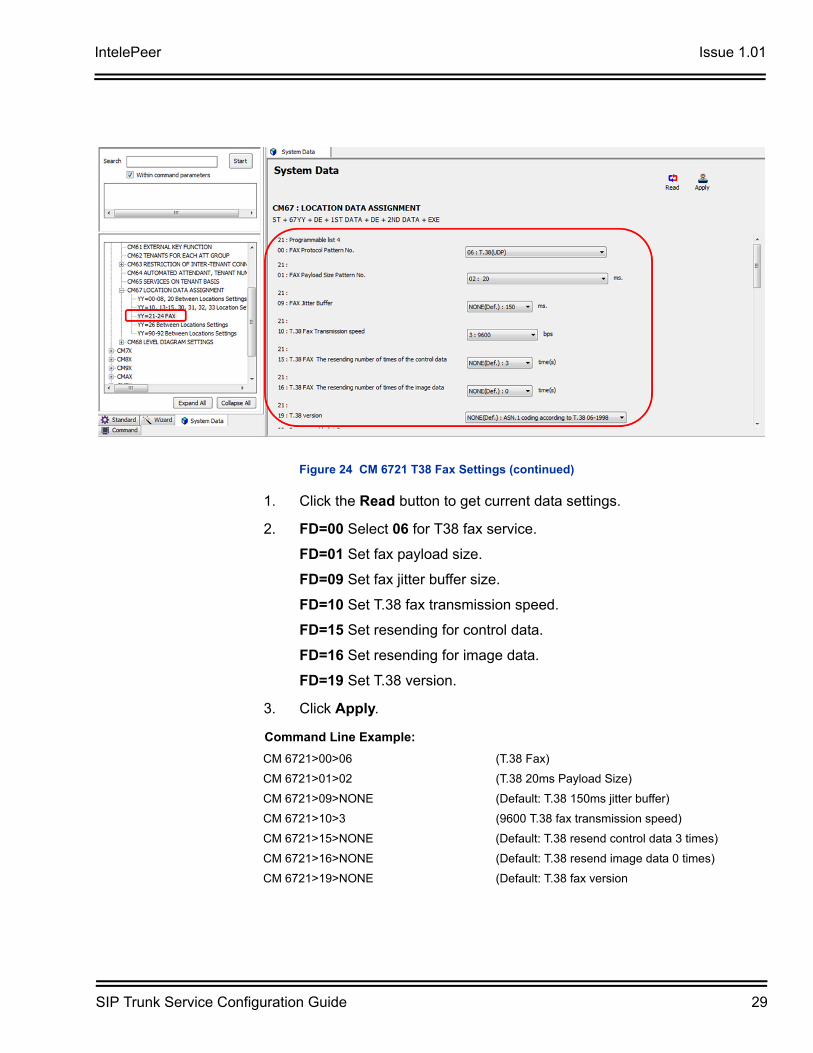
1. Click the Read button to get current data settings.
2. FD=00 Select 06 for T38 fax service.
FD=01 Set fax payload size.
FD=09 Set fax jitter buffer size.
FD=10 Set T.38 fax transmission speed.
FD=15 Set resending for control data.
FD=16 Set resending for image data.
FD=19 Set T.38 version.
3. Click Apply.
Figure 24 CM 6721 T38 Fax Settings (continued)
Command Line Example:
CM 6721>00>06 (T.38 Fax)
CM 6721>01>02 (T.38 20ms Payload Size)
CM 6721>09>NONE (Default: T.38 150ms jitter buffer)
CM 6721>10>3 (9600 T.38 fax transmission speed)
CM 6721>15>NONE (Default: T.38 resend control data 3 times)
CM 6721>16>NONE (Default: T.38 resend image data 0 times)
CM 6721>19>NONE (Default: T.38 fax version
Issue 1.01 IntelePeer
30 SIP Trunk Service Configuration Guide
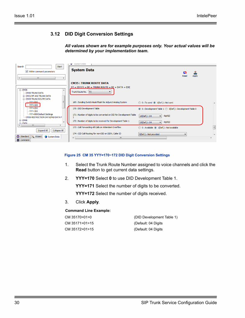
3.12 DID Digit Conversion Settings
All values shown are for example purposes only. Your actual values will be determined by your implementation team.
1. Select the Trunk Route Number assigned to voice channels and click the Read button to get current data settings.
2. YYY=170 Select 0 to use DID Development Table 1.
YYY=171 Select the number of digits to be converted.
YYY=172 Select the number of digits received.
3. Click Apply.
Figure 25 CM 35 YYY=170~172 DID Digit Conversion Settings
Command Line Example:
CM 35170>01>0 (DID Development Table 1)
CM 35171>01>15 (Default: 04 Digits
CM 35172>01>15 (Default: 04 Digits
IntelePeer Issue 1.01
SIP Trunk Service Configuration Guide 31
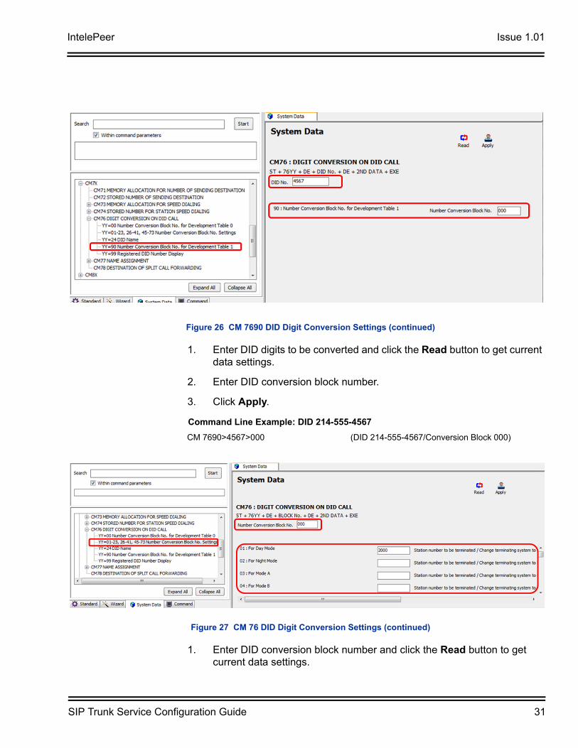
1. Enter DID digits to be converted and click the Read button to get current data settings.
2. Enter DID conversion block number.
3. Click Apply.
1. Enter DID conversion block number and click the Read button to get current data settings.
Figure 26 CM 7690 DID Digit Conversion Settings (continued)
Command Line Example: DID 214-555-4567
CM 7690>4567>000 (DID 214-555-4567/Conversion Block 000)
Figure 27 CM 76 DID Digit Conversion Settings (continued)
Issue 1.01 IntelePeer
32 SIP Trunk Service Configuration Guide
2. YY=01~04 Enter DID destination for the required system modes.
3. Click Apply.
Command Line Example: Day Mode/Destination Stn. 2000
CM 7601>000>2000 (Conversion Block 000/Destination Stn. 2000)
IntelePeer Issue 1.01
SIP Trunk Service Configuration Guide 33
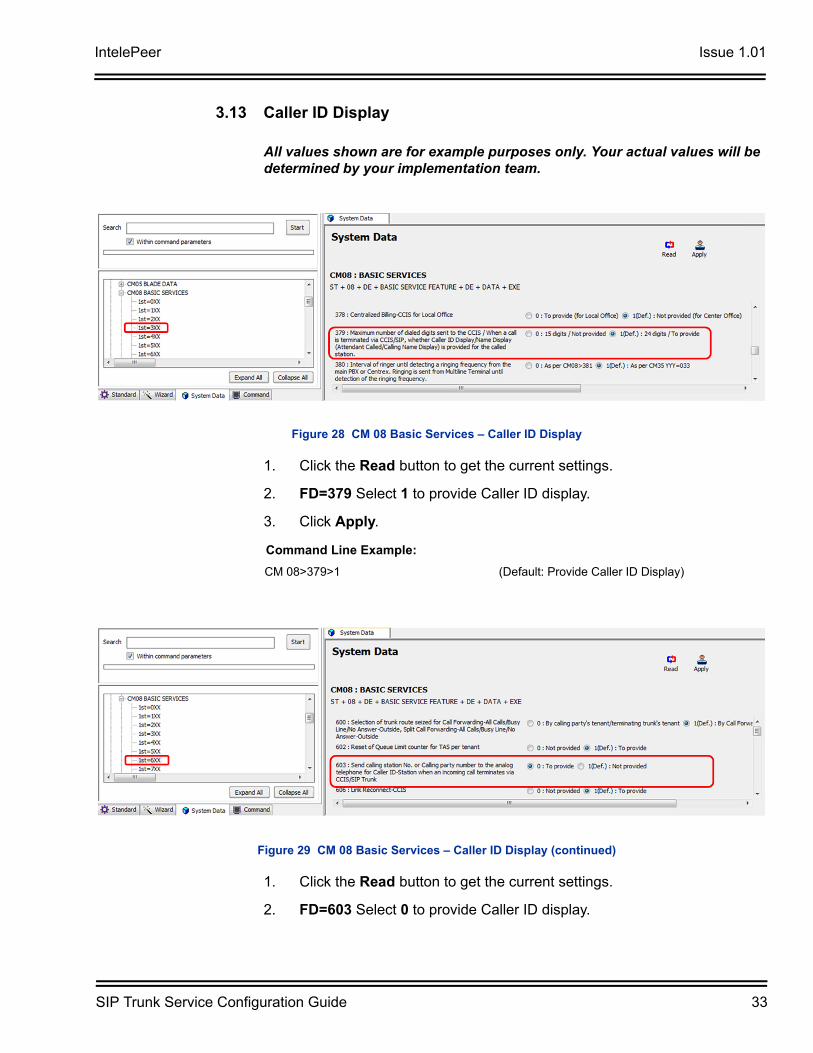
3.13 Caller ID Display
All values shown are for example purposes only. Your actual values will be determined by your implementation team.
1. Click the Read button to get the current settings.
2. FD=379 Select 1 to provide Caller ID display.
3. Click Apply.
1. Click the Read button to get the current settings.
2. FD=603 Select 0 to provide Caller ID display.
Figure 28 CM 08 Basic Services – Caller ID Display
Command Line Example:
CM 08>379>1 (Default: Provide Caller ID Display)
Figure 29 CM 08 Basic Services – Caller ID Display (continued)
Issue 1.01 IntelePeer
34 SIP Trunk Service Configuration Guide
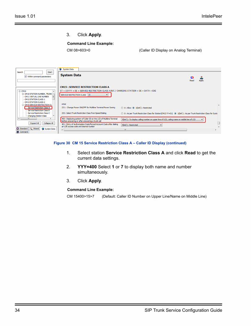
3. Click Apply.
1. Select station Service Restriction Class A and click Read to get the current data settings.
2. YYY=400 Select 1 or 7 to display both name and number simultaneously.
3. Click Apply.
Command Line Example:
CM 08>603>0 (Caller ID Display on Analog Terminal)
Figure 30 CM 15 Service Restriction Class A – Caller ID Display (continued)
Command Line Example:
CM 15400>15>7 (Default: Caller ID Number on Upper Line/Name on Middle Line)
IntelePeer Issue 1.01
SIP Trunk Service Configuration Guide 35
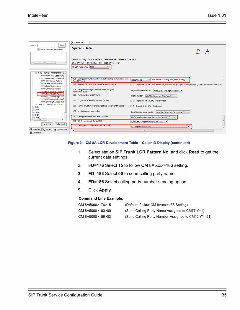
1. Select station SIP Trunk LCR Pattern No. and click Read to get the current data settings.
2. FD=176 Select 15 to follow CM 8A5xxx>186 setting.
3. FD=183 Select 00 to send calling party name.
4. FD=186 Select calling party number sending option.
5. Click Apply.
Figure 31 CM 8A LCR Development Table – Caller ID Display (continued)
Command Line Example:
CM 8A5000>176>15 (Default: Follow CM 8Axxx>186 Setting)
CM 8A5000>183>00 (Send Calling Party Name Assigned to CM77 Y=1)
CM 8A5000>186>03 (Send Calling Party Number Assigned to CM12 YY=51)
Issue 1.01 IntelePeer
36 SIP Trunk Service Configuration Guide
SECTION 4 INITIAL TESTING AND TROUBLESHOOTING
To confirm that the system is correctly set, perform the following tests:
If you run into an issue with any of these tests, refer to Table 2 Troubleshooting Guide. Test an outgoing call to a local number. Check for ringback, 2-way audio and quality.
1. Test an outgoing call to a long distance number. Check for ringback, 2-way audio and quality.
2. Test an outgoing call to an international number. Check for ringback, 2-way audio and quality.
3. Test an outgoing call lasting more than 15 minutes.
4. Test multiple call concurrences on outgoing calls. Setup multiple calls to PSTN.
5. Test an outgoing call to an Operator ‘0’.
6. Test an outgoing call to directory assistance ‘411’.
7. Test a 911 call.
8. Test an incoming call to an internal DID. Check for ringback, 2-way audio and quality.
9. Test an incoming call to an auto-attendant. Check DTMF and audio quality.
10. Test transferring calls off-site.
11. Test an outgoing call to an auto-attendant and verify DTMF.
Identify to the operator that this is a TEST!
IntelePeer Issue 1.01
SIP Trunk Service Configuration Guide 37
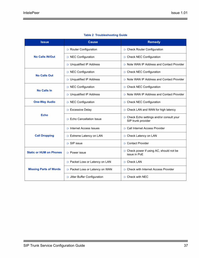
Table 2 Troubleshooting Guide
Issue Cause Remedy
No Calls IN/Out
Router Configuration Check Router Configuration
NEC Configuration Check NEC Configuration
Unqualified IP Address Note WAN IP Address and Contact Provider
No Calls Out NEC Configuration Check NEC Configuration
Unqualified IP Address Note WAN IP Address and Contact Provider
No Calls In NEC Configuration Check NEC Configuration
Unqualified IP Address Note WAN IP Address and Contact Provider
One-Way Audio NEC Configuration Check NEC Configuration
Echo
Excessive Delay Check LAN and WAN for high latency
Echo Cancellation Issue Check Echo settings and/or consult your
SIP trunk provider
Call Dropping
Internet Access Issues Call Internet Access Provider
Extreme Latency on LAN Check Latency on LAN
SIP issue Contact Provider
Static or HUM on Phones Power issue Check power if using AC, should not be
issue in PoE
Missing Parts of Words
Packet Loss or Latency on LAN Check LAN
Packet Loss or Latency on WAN Check with Internet Access Provider
Jitter Buffer Configuration Check with NEC
Issue 1.01 IntelePeer
38 SIP Trunk Service Configuration Guide
Command Line Example:
CM 0B101>00>172.24.142.55 (Unit 01 VoIP Address)
CM 0B101>01>255.255.255.0 (Unit 01 VoIP Subnet)
CM 0B101>02>172.24.142.1 (Unit 01 VoIP Default GW)
CM 0B101>10>NONE (Default: Location 00)
CM 0B101>36>NONE (Default: SIP Trunk Port 5060)
CM 0B101>60>151.164.1.8 (Unit 01 Primary DNS Server Address)
CM 0B101>61>151.164.11.201 (Unit 01 Secondary DNS Server Address)
CM 0B101>70>66.137.132.162 (Unit 01 Global IP Address)
CM 0B201>00>172.24.142.56 (Unit 01 VoIP IPPAD Address)
CM 0B101>10>32 (Unit 01 VoIP IPPAD Channels)
CM 0B101>50>1 (Unit 01 Allow Fax over IP)
CM 1003>01000>D001 (Unit 01 SIP Trunk Channel 1)
CM 1003>01001>D002 (Unit 01 SIP Trunk Channel 2)
CM 1003>01002>D003 (Unit 01 SIP Trunk Channel 3)
CM 1003>01003>D004 (Unit 01 SIP Trunk Channel 4)
CM 3000>001>01 (Voice Trunk Route Number 01)
CM 3000>002>01 (Voice Trunk Route Number 01)
CM 3000>003>01 (Voice Trunk Route Number 01)
CM 3000>004>01 (Voice Trunk Route Number 01)
CM 3035>001>001 (Assign CIC to Channel 1)
CM 3035>002>002 (Assign CIC to Channel 2)
CM 3035>003>003 (Assign CIC to Channel 3)
CM 3035>004>004 (Assign CIC to Channel 4)
CM 35000>01>00 (SIP Trunk Route Data: Provide SIP Service)
CM 35004>01>2 (SIP Trunk Route Data: Provide SIP Service)
CM 35009>01>03 (SIP Trunk Route Data: Provide SIP Service)
CM 35018>01>0 (SIP Trunk Route Data: Provide DID Digit Conversion)
CM 35020>01>00 (SIP Trunk Route Data: Provide SIP Service)
CM 35090>01>0 (SIP Trunk Route Data: Provide SIP Service)
CM 35091>01>01 (SIP Trunk Route Data: Assign CCH Number)
CM 35161>01>2E (SIP Trunk Route Data: SIP Control QoS DiffServ EF)
CM 35170>01>0 (DID Development Table 1)
CM 35171>01>15 (Default: 04 Digits)
CM 35172>01>15 (Default: 04 Digits)
CM 360>0101>0 (Route to Route Connection)
CM A701>01>00400 (Arbitrary Origination Point Code)
CM A702>01>00401 (Arbitrary Destination Point Code)
CM A771>01>00 (Assign SIP Trunk Profile Number)
CM A778>01>01 (Assign SV9300 Unit Number with SIP Trunk Channels)
IntelePeer Issue 1.01
SIP Trunk Service Configuration Guide 39
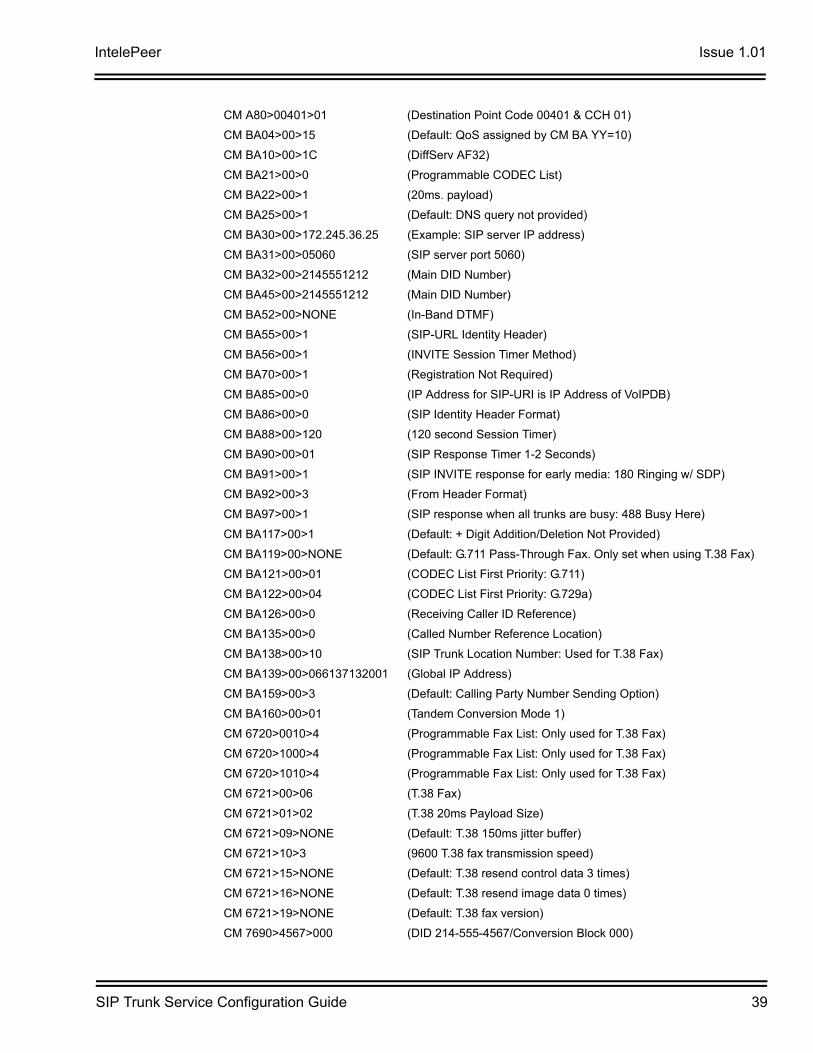
CM A80>00401>01 (Destination Point Code 00401 & CCH 01)
CM BA04>00>15 (Default: QoS assigned by CM BA YY=10)
CM BA10>00>1C (DiffServ AF32)
CM BA21>00>0 (Programmable CODEC List)
CM BA22>00>1 (20ms. payload)
CM BA25>00>1 (Default: DNS query not provided)
CM BA30>00>172.245.36.25 (Example: SIP server IP address)
CM BA31>00>05060 (SIP server port 5060)
CM BA32>00>2145551212 (Main DID Number)
CM BA45>00>2145551212 (Main DID Number)
CM BA52>00>NONE (In-Band DTMF)
CM BA55>00>1 (SIP-URL Identity Header)
CM BA56>00>1 (INVITE Session Timer Method)
CM BA70>00>1 (Registration Not Required)
CM BA85>00>0 (IP Address for SIP-URI is IP Address of VoIPDB)
CM BA86>00>0 (SIP Identity Header Format)
CM BA88>00>120 (120 second Session Timer)
CM BA90>00>01 (SIP Response Timer 1-2 Seconds)
CM BA91>00>1 (SIP INVITE response for early media: 180 Ringing w/ SDP)
CM BA92>00>3 (From Header Format)
CM BA97>00>1 (SIP response when all trunks are busy: 488 Busy Here)
CM BA117>00>1 (Default: + Digit Addition/Deletion Not Provided)
CM BA119>00>NONE (Default: G.711 Pass-Through Fax. Only set when using T.38 Fax)
CM BA121>00>01 (CODEC List First Priority: G.711)
CM BA122>00>04 (CODEC List First Priority: G.729a)
CM BA126>00>0 (Receiving Caller ID Reference)
CM BA135>00>0 (Called Number Reference Location)
CM BA138>00>10 (SIP Trunk Location Number: Used for T.38 Fax)
CM BA139>00>066137132001 (Global IP Address)
CM BA159>00>3 (Default: Calling Party Number Sending Option)
CM BA160>00>01 (Tandem Conversion Mode 1)
CM 6720>0010>4 (Programmable Fax List: Only used for T.38 Fax)
CM 6720>1000>4 (Programmable Fax List: Only used for T.38 Fax)
CM 6720>1010>4 (Programmable Fax List: Only used for T.38 Fax)
CM 6721>00>06 (T.38 Fax)
CM 6721>01>02 (T.38 20ms Payload Size)
CM 6721>09>NONE (Default: T.38 150ms jitter buffer)
CM 6721>10>3 (9600 T.38 fax transmission speed)
CM 6721>15>NONE (Default: T.38 resend control data 3 times)
CM 6721>16>NONE (Default: T.38 resend image data 0 times)
CM 6721>19>NONE (Default: T.38 fax version)
CM 7690>4567>000 (DID 214-555-4567/Conversion Block 000)
Issue 1.01 IntelePeer
40 SIP Trunk Service Configuration Guide
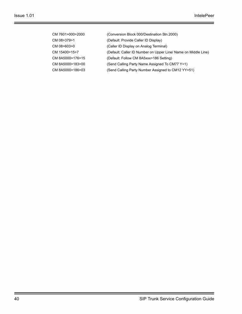
CM 7601>000>2000 (Conversion Block 000/Destination Stn.2000)
CM 08>379>1 (Default: Provide Caller ID Display)
CM 08>603>0 (Caller ID Display on Analog Terminal)
CM 15400>15>7 (Default: Caller ID Number on Upper Line/ Name on Middle Line)
CM 8A5000>176>15 (Default: Follow CM 8A5xxx>186 Setting)
CM 8A5000>183>00 (Send Calling Party Name Assigned To CM77 Y=1)
CM 8A5000>186>03 (Send Calling Party Number Assigned to CM12 YY=51)


![Intelepeer SIP Trunking: Connecting Cisco Unified ... · [IOS-XE – 16.09.01] for connectivity to Intelepeer SIP Trunking service. The deployment model covered in this application](https://static.documents.pub/doc/80x56/5fb0ceedf8194901a87afa58/intelepeer-sip-trunking-connecting-cisco-unified-ios-xe-a-160901-for.jpg)


