SS-EN 13445-3:2021 SVENSK STANDARD Språk: engelska / English Utgåva: 4 Tryckkärl (ej eldberörda) – Del 3: Konstruktion Unfired pressure vessels – Part 3: Design This preview is downloaded from www.sis.se. Buy the entire This preview is downloaded from www.sis.se. Buy the entire This preview is downloaded from www.sis.se. Buy the entire This preview is downloaded from www.sis.se. Buy the entire standard via https://www.sis.se/std-80029427 standard via https://www.sis.se/std-80029427 standard via https://www.sis.se/std-80029427 standard via https://www.sis.se/std-80029427
Transcript
SS-EN 13445-3:2021SVENSK STANDARD
Språk: engelska / EnglishUtgåva: 4
Tryckkärl (ej eldberörda) – Del 3: Konstruktion
Unfired pressure vessels – Part 3: Design
This preview is downloaded from www.sis.se. Buy the entireThis preview is downloaded from www.sis.se. Buy the entireThis preview is downloaded from www.sis.se. Buy the entireThis preview is downloaded from www.sis.se. Buy the entirestandard via https://www.sis.se/std-80029427standard via https://www.sis.se/std-80029427standard via https://www.sis.se/std-80029427standard via https://www.sis.se/std-80029427
Upplysningar om sakinnehållet i standarden lämnas av Svenska institutet för standarder, telefon 08 - 555 520 00. Standarder kan beställas hos SIS som även lämnar allmänna upplysningar om svensk och utländsk standard.
Standarden är framtagen av kommittén för Konstruktion, tillverkning och kontroll av tryckbärande anordningar, SIS / TK 298.
Har du synpunkter på innehållet i den här standarden, vill du delta i ett kommande revideringsarbete eller vara med och ta fram andra standarder inom området? Gå in på www.sis.se - där hittar du mer information.
Den här standarden kan hjälpa dig att effektivisera och kvalitetssäkra ditt arbete. SIS har fler tjänster att erbjuda dig för att underlätta tillämpningen av standarder i din verksamhet.
SIS AbonnemangSnabb och enkel åtkomst till gällande standard med SIS Abonnemang, en prenumerationstjänst genom vilken din orga-nisation får tillgång till all världens standarder, senaste uppdateringarna och där hela din organisation kan ta del av innehållet i prenumerationen.
Utbildning, event och publikationerVi erbjuder även utbildningar, rådgivning och event kring våra mest sålda standarder och frågor kopplade till utveckling av standarder. Vi ger också ut handböcker som underlättar ditt arbete med att använda en specifik standard.
Vill du delta i ett standardiseringsprojekt?Genom att delta som expert i någon av SIS 300 tekniska kommittéer inom CEN (europeisk standardisering) och / eller ISO (internationell standardisering) har du möjlighet att påverka standardiseringsarbetet i frågor som är viktiga för din organisation. Välkommen att kontakta SIS för att få veta mer!
KontaktSkriv till [email protected], besök sis.se eller ring 08 - 555 523 10
This preview is downloaded from www.sis.se. Buy the entire standard via https://www.sis.se/std-80029427
Europastandarden EN 13445-3:2021 gäller som svensk standard. Detta dokument innehåller den officiella engelska versionen av EN 13445-3:2021. Denna standard ersätter SS-EN 13445-3:2014+C5:2018 utgåva 1, SS-EN 13445-3/A5:2018 utgåva 1, SS-EN 13445-3/A6:2019 utgåva 1, SS-EN 13445-3/A7:2019 utgåva 1 och SS-EN 13445-3/A8:2019 utgåva 1.
The European Standard EN 13445-3:2021 has the status of a Swedish Standard. This document contains the official version of EN 13445-3:2021. This standard supersedes the Swedish Standard SS-EN 13445-3:2014+C5:2018 edition 1, SS-EN 13445-3/A5:2018 edition 1, SS-EN 13445-3/A6:2019 edition 1, SS-EN 13445-3/A7:2019 edition 1 and SS-EN 13445-3/A8:2019 edition 1.
This preview is downloaded from www.sis.se. Buy the entire standard via https://www.sis.se/std-80029427
LÄSANVISNINGAR FÖR STANDARDER
I dessa anvisningar behandlas huvudprinciperna för hur regler och yttre begränsningar anges i standardiseringsprodukter.
KravEtt krav är ett uttryck i ett dokuments innehåll som anger objektivt verifierbara kriterier som ska uppfyllas och från vilka ing-en avvikelse tillåts om efterlevnad av dokumentet ska kunna åberopas. Krav uttrycks med hjälpverbet ska (eller ska inte för förbud).
RekommendationEn rekommendation är ett uttryck i ett dokuments innehåll som anger en valmöjlighet eller ett tillvägagångssätt som be-döms vara särskilt lämpligt utan att nödvändigtvis nämna eller utesluta andra. Rekommendationer uttrycks med hjälpver-bet bör (eller bör inte för avrådanden).
InstruktionInstruktioner anges i imperativ form och används för att ange hur något görs eller utförs. De kan underordnas en annan re-gel, såsom ett krav eller en rekommendation. De kan även användas självständigt, och är då att betrakta som krav.
FörklaringEn förklaring är ett uttryck i ett dokuments innehåll som förmedlar information. En förklaring kan uttrycka tillåtelse, möjlig-het eller förmåga. Tillåtelse uttrycks med hjälpverbet får (eller motsatsen behöver inte). Möjlighet och förmåga uttrycks med hjälpverbet kan (eller motsatsen kan inte).
READING INSTRUCTIONS FOR STANDARDS
These instructions cover the main principles for the use of provisions and external constraints in standardization delivera-bles.
RequirementA requirement is an expression, in the content of a document, that conveys objectively verifiable criteria to be fulfilled, and from which no deviation is permitted if conformance with the document is to be claimed. Requirements are expressed by the auxiliary shall (or shall not for prohibition).
RecommendationA recommendation is an expression, in the content of a document, that conveys a suggested possible choice or course of action deemed to be particularly suitable, without necessarily mentioning or excluding others. Recommendations are ex-pressed by the auxiliary should (or should not for dissuasion).
InstructionAn instruction is expressed in the imperative mood and is used in order to convey an action to be performed. It can be sub-ordinated to another provision, such as a requirement or a recommendation. It can also be used independently and is then to be regarded as a requirement.
StatementA statement is an expression, in the content of a document, that conveys information. A statement can express permis-sion, possibility or capability. Permission is expressed by the auxiliary may (its opposite being need not). Possibility and capability are expressed by the auxiliary can (its opposite being cannot).
This preview is downloaded from www.sis.se. Buy the entire standard via https://www.sis.se/std-80029427
EUROPEAN STANDARD NORME EUROPÉENNE EUROPÄISCHE NORM
EN 13445-3 May 2021
ICS 23.020.30 Supersedes EN 13445-3:2014English Version Unfired pressure vessels - Part 3: Design Récipients sous pression non soumis à la flamme - Partie 3: Conception Unbefeuerte Druckbehälter - Teil 3: Konstruktion
This European Standard was approved by CEN on 24 February 2021. CEN members are bound to comply with the CEN/CENELEC Internal Regulations which stipulate the conditions for giving this European Standard the status of a national standard without any alteration. Up-to-date lists and bibliographical references concerning such national standards may be obtained on application to the CEN-CENELEC Management Centre or to any CEN member. This European Standard exists in three official versions (English, French, German). A version in any other language made by translation under the responsibility of a CEN member into its own language and notified to the CEN-CENELEC Management Centre has the same status as the official versions. CEN members are the national standards bodies of Austria, Belgium, Bulgaria, Croatia, Cyprus, Czech Republic, Denmark, Estonia, Finland, France, Germany, Greece, Hungary, Iceland, Ireland, Italy, Latvia, Lithuania, Luxembourg, Malta, Netherlands, Norway, Poland, Portugal, Republic of North Macedonia, Romania, Serbia, Slovakia, Slovenia, Spain, Sweden, Switzerland, Turkey and United Kingdom.
EUROPEAN COMMITTEE FOR STANDARDIZATION C O M I T É E U R O P É E N D E N O R M A L I S A T I O N E U R O P Ä I S C H E S K O M I T E E F Ü R N O R M U N G CEN-CENELEC Management Centre: Rue de la Science 23, B-1040 Brussels
5.1 General .......................................................................................................................................................... 15
5.2 Corrosion, erosion and protection ...................................................................................................... 15
5.7 Design requirements of welded joints .............................................................................................. 29
6 Maximum allowed values of the nominal design stress for pressure parts ........................ 32
6.1 General .......................................................................................................................................................... 32
6.2 Steels (except castings), other than austenitic steels covered by 6.4 and 6.5, with a minimum rupture elongation, as given in the relevant technical specification for the material, below 30 % ............................................................................................................................... 33
6.3 Alternative route for steels (except castings), other than austenitic steels covered by 6.4 and 6.5, with a minimum rupture elongation, as given in the relevant technical specification for the material, below 30 % ...................................................................................... 33
6.4 Austenitic steels (except castings) with a minimum rupture elongation, A%, as given in the relevant technical specification for the material, such as 30%≤A%<35% .................. 34
6.5 Austenitic steels (except castings) with a minimum rupture elongation, A%, as given in the relevant technical specification for the material, such as A%≥35% .............................. 34
7.2 Specific definitions ................................................................................................................................... 36
7.3 Specific symbols and abbreviations ................................................................................................... 37
7.4 Cylindrical and spherical shells ........................................................................................................... 37
8.2 Specific definitions ................................................................................................................................... 56
8.3 Specific symbols and definitions ......................................................................................................... 57
8.4 General .......................................................................................................................................................... 60
This preview is downloaded from www.sis.se. Buy the entire standard via https://www.sis.se/std-80029427
9.2 Specific definitions ................................................................................................................................... 90
9.3 Specific symbols and abbreviations ................................................................................................... 91
9.4 General ......................................................................................................................................................... 95
10.2 Specific definitions ................................................................................................................................ 142
10.3 Specific symbols and abbreviations ................................................................................................ 143
11.2 Specific definitions ................................................................................................................................ 163
11.3 Specific symbols and abbreviations ................................................................................................ 164
11.4 General ...................................................................................................................................................... 166
11.5 Narrow face gasketed flanges ............................................................................................................ 170
11.6 Full face flanges with soft ring type gaskets ................................................................................. 186
11.7 Seal welded flanges ............................................................................................................................... 189
11.8 Reverse narrow face flanges .............................................................................................................. 189
11.9 Reverse full face flanges ...................................................................................................................... 192
11.10 Full face flanges with metal to metal contact ............................................................................... 196
12.2 Specific definitions ................................................................................................................................ 199
12.3 Specific symbols and abbreviations ................................................................................................ 199
12.4 General ...................................................................................................................................................... 199
12.5 Bolted domed ends with narrow face gaskets ............................................................................. 199
This preview is downloaded from www.sis.se. Buy the entire standard via https://www.sis.se/std-80029427
EN 13445-3:2021 (E) Issue 1 (2021-05)
4
12.6 Bolted domed ends with full face joints ......................................................................................... 201
13.2 Specific definitions ................................................................................................................................ 203
13.3 Specific symbols and abbreviations ................................................................................................ 203
14.2 Specific definitions ................................................................................................................................ 288
14.3 Specific symbols and abbreviations ................................................................................................ 290
14.4 Conditions of applicability .................................................................................................................. 293
15.2 Specific definitions ................................................................................................................................ 335
15.3 Specific symbols and abbreviations ................................................................................................ 335
15.4 General ....................................................................................................................................................... 337
16.2 Specific definitions ................................................................................................................................ 357
16.3 Specific symbols and abbreviations ................................................................................................ 357
16.4 Local loads on nozzles in spherical shells ..................................................................................... 359
This preview is downloaded from www.sis.se. Buy the entire standard via https://www.sis.se/std-80029427
EN 13445-3:2021 (E) Issue 1 (2021-05)
5
16.5 Local loads on nozzles in cylindrical shells .................................................................................. 370
16.6 Line loads .................................................................................................................................................. 379
17.2 Specific definitions ................................................................................................................................ 474
17.3 Specific symbols and abbreviations ................................................................................................ 477
17.4 Conditions of applicability.................................................................................................................. 479
17.5 General ...................................................................................................................................................... 480
17.6 Determination of allowable number of pressure and thermal cycles ................................ 488
18.2 Specific definitions ................................................................................................................................ 515
18.3 Specific symbols and abbreviations ................................................................................................ 519
18.5 General ...................................................................................................................................................... 522
18.6 Welded material ..................................................................................................................................... 525
18.7 Unwelded components and bolts ..................................................................................................... 530
19.2 Specific definitions ................................................................................................................................ 568
19.3 Specific symbols and abbreviations ................................................................................................ 568
19.4 Design in the creep range ................................................................................................................... 569
This preview is downloaded from www.sis.se. Buy the entire standard via https://www.sis.se/std-80029427
EN 13445-3:2021 (E) Issue 1 (2021-05)
6
19.5 Nominal Design stress in the creep range ..................................................................................... 570
19.6 Weld joint factor in the creep range ................................................................................................ 574
19.7 Pressure loading of predominantly non-cyclic nature in the creep range ....................... 574
19.8 Design procedures for DBF ................................................................................................................. 574
20 Design rules for reinforced flat walls ............................................................................................. 577
20.1 General ....................................................................................................................................................... 577
21.2 Specific definitions ................................................................................................................................ 584
21.3 Specific symbols and abbreviations ................................................................................................ 586
21.4 Ends without additional peripheral bending moment ............................................................. 587
21.5 Ends with additional peripheral bending moment ................................................................... 589
21.8 Central Ring .............................................................................................................................................. 594
22 Static analysis of tall vertical vessels on skirts ........................................................................... 595
22.2 Specific definitions ................................................................................................................................ 595
22.3 Specific symbols and abbreviations ................................................................................................ 595
22.6 Stress analysis of pressure vessel shells and skirts .................................................................. 600
22.7 Design of joint between skirt and pressure vessel (at dished end or cylindrical shell)....................................................................................................................................................................... 601
22.8 Design of anchor bolts and base ring assembly .......................................................................... 601
22.9 Foundation loads .................................................................................................................................... 601
Annex A (normative) Design requirements for pressure bearing welds ........................................ 606
Annex B (normative) Design by Analysis – Direct Route ...................................................................... 630
Annex C (normative) Design by analysis — Method based on stress categories ......................... 662
Annex D (informative) Verification of the shape of vessels subject to external pressure ........ 684
This preview is downloaded from www.sis.se. Buy the entire standard via https://www.sis.se/std-80029427
EN 13445-3:2021 (E) Issue 1 (2021-05)
7
Annex E (normative) Procedure for calculating the departure from the true circle of cylinders and cones .................................................................................................................................................. 691
Annex F (normative) Allowable external pressure for vessels outside circularity tolerance 694
Annex G (normative) Alternative design rules for flanges and gasketed flange connections 696
Annex H (informative) Gasket factors m and y ......................................................................................... 746
Annex I (normative) Additional information on heat exchanger tubesheet design ................... 749
Annex J (normative) Alternative method for the design of heat exchanger tubesheets ........... 753
Annex K (informative) Additional information on expansion bellows design ............................. 802
Annex L (informative) Basis for design rules related to additional non-pressure loads ......... 809
Annex M (informative) In service monitoring of vessels operating in fatigue or creep service ...................................................................................................................................................................... 811
Annex N (informative) Bibliography to Clause 18 .................................................................................. 814
Annex O (informative) Physical properties of steels ............................................................................. 815
Annex P (normative) Classification of weld details to be assessed using principal stresses .. 823
Annex Q (normative) Simplified procedure for the fatigue assessment of unwelded zones .. 836
Annex R (informative) Coefficients for creep-rupture model equations for extrapolation of creep-rupture strength ........................................................................................................................ 837
Annex S (informative) Extrapolation of the nominal design stress based on time-independent behaviour in the creep range ............................................................................................................ 844
Annex T (normative) Design by experimental methods ....................................................................... 849
Annex U (informative) Guidance on negligibility of additional thermal cycles in fatigue and ratcheting assessment ......................................................................................................................... 863
Annex V (informative) Consider a buffer for unknown nozzle loads — Opening design for unknown nozzle loads .......................................................................................................................... 872
Annex Y (informative) History of EN 13445-3 .......................................................................................... 873
Annex ZA (informative) Relationship between this European Standard and the essential requirements of Directive 2014/68/EU aimed to be covered............................................... 874
This preview is downloaded from www.sis.se. Buy the entire standard via https://www.sis.se/std-80029427
EN 13445-3:2021 (E) Issue 1 (2021-05)
8
European foreword
This document (EN 13445-3:2021) has been prepared by Technical Committee CEN/TC 54 “Unfired pressure vessels”, the secretariat of which is held by BSI.
This European Standard shall be given the status of a national standard, either by publication of an identical text or by endorsement, at the latest by November 2021, and conflicting national standards shall be withdrawn at the latest by November 2021.
Attention is drawn to the possibility that some of the elements of this document may be the subject of patent rights. CEN shall not be held responsible for identifying any or all such patent rights.
This document has been prepared under a standardization request given to CEN by the European Commission and the European Free Trade Association, and supports essential requirements of EU Directive(s).
For relationship with EU Directive(s), see informative Annex ZA, which is an integral part of this document.
List of all parts in the EN 13445 series can be found on the CEN website.
Although these Parts may be obtained separately, it should be recognised that the Parts are inter-dependant. As such the manufacture of unfired pressure vessels requires the application of all the relevant Parts in order for the requirements of the Standard to be satisfactorily fulfilled.
Corrections to the standard interpretations where several options seem possible are conducted through the Migration Help Desk (MHD). Information related to the Help Desk can be found at http://www.unm.fr ([email protected]). A form for submitting questions can be downloaded from the link to the MHD website. After subject experts have agreed an answer, the answer will be communicated to the questioner. Corrected pages will be given specific issue number and issued by CEN according to CEN Rules. Interpretation sheets will be posted on the website of the MHD.
This document supersedes EN 13445-3:2014. This new edition incorporates the Amendments which have been approved previously by CEN members, and the corrected pages up to Issue 5 without any further technical change. Annex Y provides details of significant technical changes between this European Standard and the previous edition.
Amendments to this new edition may be issued from time to time and then used immediately as alternatives to rules contained herein. It is intended to deliver a new Issue of EN 13445:2021 each year, starting with the precedent as Issue 1, consolidating these Amendments and including other identified corrections.
According to the CEN-CENELEC Internal Regulations, the national standards organizations of the following countries are bound to announce this European Prestandard: Austria, Belgium, Bulgaria, Croatia, Cyprus, Czech Republic, Denmark, Estonia, Finland, Former Yugoslav Republic of Macedonia, France, Germany, Greece, Hungary, Iceland, Ireland, Italy, Latvia, Lithuania, Luxembourg, Malta, Netherlands, Norway, Poland, Portugal, Romania, Serbia, Slovakia, Slovenia, Spain, Sweden, Switzerland, Turkey and the United Kingdom.
This preview is downloaded from www.sis.se. Buy the entire standard via https://www.sis.se/std-80029427
This Part of this document specifies requirements for the design of unfired pressure vessels covered by EN 13445-1:2021 and constructed of steels in accordance with EN 13445-2:2021.
EN 13445-5:2021EN 13445-5:2021, Annex C specifies requirements for the design of access and inspection openings, closing mechanisms and special locking elements.
NOTE This Part applies to design of vessels before putting into service. It may be used for in service calculation or analysis subject to appropriate adjustment.
2 Normative references
The following documents are referred to in the text in such a way that some or all of their content constitutes requirements of this document. For dated references, only the edition cited applies. For undated references, the latest edition of the referenced document (including any amendments) applies.
EN 286-2:1992, Simple unfired pressure vessels designed to contain air or nitrogen — Part 2: Pressure vessels for air braking and auxiliary systems for motor vehicles and their trailers
EN 764-1:2015+A1:2016, Pressure equipment — Terminology — Part 1: Pressure, temperature, volume, nominal size
EN 764-2:2012, Pressure equipment — Part 2: Quantities, symbols and units
EN 764-3:2002, Pressure equipment — Part 3: Definition of parties involved
EN 837-1:1996, Pressure gauges — Part 1: Bourdon tube pressure gauges — Dimensions, metrology, requirements and testing
EN 837-3:1996, Pressure gauges — Part 3: Diaphragm and capsule pressure gauges — Dimensions, metrology, requirements and testing
EN 1092-1:2018, Flanges and their joints — Circular flanges for pipes, valves, fittings and accessories, PN-designated — Part 1: Steel flanges
EN 1591-1:2013, Flanges and their joints — Design rules for gasketed circular flange connections — Calculation method
EN 1708-1:2010, Welding — Basic weld joint details in steel — Part 1: Pressurized components
EN 1990:20021), Eurocode — Basis of structural design
EN 1992-1-1:2005, Eurocode 2 — Design of concrete structures — Part 1-1: General rules and rules for buildings
EN 1991-1-4:20052), Eurocode 1: Actions on structures — Part 1-4: General actions — Wind actions
1) EN 1990:2002 is impacted by the stand-alone amendment EN 1990:2002/A1:2005 and the corrigendum EN 1990:2002/AC:2010.
2) EN 1991-1-4:2005 is impacted by the stand-alone amendment EN 1991-1-4:2005/A1:2010 and the corrigendum EN 1991-1-4:2005/AC:2010.
This preview is downloaded from www.sis.se. Buy the entire standard via https://www.sis.se/std-80029427
EN 13445-3:2021 (E) Issue 1 (2021-05)
10
EN 1991-1-6:2005, Eurocode 1 — Actions on structures — Part 1-6: General actions — Actions during execution
EN 1998-1:2004, Design of structures for earthquake resistance — Part 1: General rules, seismic actions and rules for buildings
EN 10204:2004, Metallic products – Type of inspection documents
EN 10222-1:1998, EN 10222-1:1998/A1:2002, Steel forgings for pressure purposes — Part 1: General requirements for open die forgings
EN 12195-1:2010, Load restraining on road vehicles — Safety — Part 1: Calculation of securing forces
EN 13445-1:2021, Unfired pressure vessels — Part 1: General
EN 13445-2:2021, Unfired pressure vessels — Part 2: Materials
EN 13445-4:2021, Unfired pressure vessels — Part 4: Fabrication
EN 13445-5:2021EN 13445-5:2021, Unfired pressure vessels — Part 5: Inspection and testing
EN 13445-8:2021, Unfired pressure vessels — Part 8: Additional requirements for pressure vessels of aluminium and aluminium alloys
EN 13555:2014, Flanges and their joints — Gasket parameters and test procedures relevant to the design rules for gasketed circular flange connections
EN ISO 4014:2011, Hexagon head bolts — Product grades A and B (ISO 4014:2011)
EN ISO 4016:2011, Hexagon head bolts — Product grade C (ISO 4016:2011)
EN ISO 15613:2004, Specification and qualification of welding procedures for metallic materials — Qualification based on pre-production welding test
ISO 261:1998, ISO general purpose metric threads — General plan
3 Terms and definitions
For the purposes of this Part of this document, the terms and definitions given in EN 13445-1:2021, EN 13445-2:2021 and the following apply:
ISO and IEC maintain terminological databases for use in standardization at the following addresses:
— IEC Electropedia: available at http://www.electropedia.org/
— ISO Online browsing platform: available at http://www.iso.org/obp
NOTE EN 13445-1:2021 and EN 13445-2:2021 have adopted terminology, symbols and definitions of EN 764-1:2015+A1:2016, EN 764-2:2012 and EN 764-3:2002.
3.1 action imposed thermo-mechanical influence which causes stress and/or strain in a structure, e.g. an imposed pressure, force, temperature
This preview is downloaded from www.sis.se. Buy the entire standard via https://www.sis.se/std-80029427
3.2 analysis thickness effective thickness available to resist the loading depending on the load case, see 5.3.2
3.3 assumed thickness thickness assumed by the designer between the minimum required shell thickness e and the shell analysis thickness ea
3.4 calculation pressure differential pressure used for the purpose of the design calculations for a component
[SOURCE: EN 764-1:2015+A1:2016]
3.5 calculation temperature temperature used for the purpose of the design calculations for a component
[SOURCE: EN 764-1:2015+A1:2016]
3.6 chamber fluid space within a unit of pressure equipment
[SOURCE: EN 764-1:2015+A1:2016]
3.7 component part of pressure equipment which can be considered as an individual item for the calculation
[SOURCE: EN 764-1:2015+A1:2016]
3.8 creep range temperature range in which material characteristics used in design are time dependent
Note 1 to entry: See also 5.1.
3.9 cryogenic applications applications involving liquefied gases at low temperature
3.10 design pressure pressure at the top of each chamber of the pressure equipment chosen for the derivation of the calculation pressure of each component
[SOURCE: EN 764-1:2015+A1:2016]
Note 1 to entry: Any other location may be specified.
This preview is downloaded from www.sis.se. Buy the entire standard via https://www.sis.se/std-80029427
EN 13445-3:2021 (E) Issue 1 (2021-05)
12
3.11 design temperature temperature chosen for the derivation of the calculation temperature of each component
[SOURCE: EN 764-1:2015+A1:2016]
3.12 differential pressure pressure which algebraic value is equal to the pressure difference on either side of a separation wall
[SOURCE: EN 764-1:2015+A1:2016]
3.13 governing weld joint main full penetration butt joint the design of which, as a result of membrane stresses, governs the thickness of the component
3.14 load case combination of coincident actions
3.15 main joint weld joint assembling main pressure bearing parts
3.16 maximum permissible pressure maximum pressure obtained from the design by formulae or relevant procedures of EN 13445-3:2021 for a given compoment in a given load case, or for the whole pressure vessel the minimum of these maximum permissible pressures of all compoments
Note 1 to entry: The differences of the nominal design stress f, the analysis thickness ea and the joint coefficient z for the calculation of the maximum permissible pressure in different load cases are specified in 5.3.2.
Note 2 to entry: If no explicit formula is given for the maximum permissible pressure Pmax then Pmax may be calculated as pressure which gives the required thickness equal to the analysis thickness.
Note 3 to entry: The maximum permissible pressure Pmax used for the simplified assessment of fatigue life in Clause 17 and for the calculation of the equivalent full pressure in 5.4.2 is calculated for normal operating load cases.
3.17 minimum possible fabrication thickness minimum possible thickness after fabrication
3.18 nominal design stress stress value to be used in the formulae for the calculation of pressure components
3.19 nominal thickness thickness as specified on the drawings
3.20 test pressure pressure to which the equipment is subjected for test purposes
[SOURCE: EN 764-1:2015+A1:2016]
This preview is downloaded from www.sis.se. Buy the entire standard via https://www.sis.se/std-80029427
EN 13445-3:2021 (E) Issue 1 (2021-05)
13
3.21 test temperature temperature at which the pressure test of the pressure equipment is carried out
[SOURCE: EN 764-1:2015+A1:2016]
3.22 volume internal volume of a chamber, including the volume of nozzles to the first connection (flange, coupling, weld) and excluding the volume of internal permanent parts (e.g. baffles, agitators)
[SOURCE: EN 764-1:2015+A1:2016]
3.23 weld throat thickness of a fillet weld height of the inscribed isosceles triangle measured from the theoretical root point
4 Symbols and abbreviations
For the purposes of this Part of this document, the general symbols and abbreviations shall be in accordance with EN 13445-1:2021, EN 13445-2:2021 and Table 4-1:
This preview is downloaded from www.sis.se. Buy the entire standard via https://www.sis.se/std-80029427
EN 13445-3:2021 (E) Issue 1 (2021-05)
14
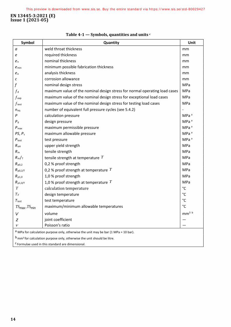
Table 4-1 — Symbols, quantities and units c
Symbol Quantity Unit a weld throat thickness mm e required thickness mm en nominal thickness mm emin minimum possible fabrication thickness mm ea analysis thickness mm c corrosion allowance mm f nominal design stress MPa ƒd maximum value of the nominal design stress for normal operating load cases MPa ƒexp maximum value of the nominal design stress for exceptional load cases MPa ƒtest maximum value of the nominal design stress for testing load cases MPa neq number of equivalent full pressure cycles (see 5.4.2) - P calculation pressure MPa a Pd design pressure MPa a Pmax maximum permissible pressure MPa a PS, Ps maximum allowable pressure MPa a Ptest test pressure MPa a ReH upper yield strength MPa Rm tensile strength MPa Rm/T tensile strength at temperature T MPa Rp0,2 0,2 % proof strength MPa Rp0,2/T 0,2 % proof strength at temperature T MPa Rp1,0 1,0 % proof strength MPa Rp1,0/T 1,0 % proof strength at temperature T MPa T calculation temperature °C Td design temperature °C Ttest test temperature °C
minmax,TSTS maximum/minimum allowable temperatures °C
V volume mm3 b z ν
joint coefficient Poisson's ratio
— —
a MPa for calculation purpose only, otherwise the unit may be bar (1 MPa = 10 bar). b mm3 for calculation purpose only, otherwise the unit should be litre. c Formulae used in this standard are dimensional.
This preview is downloaded from www.sis.se. Buy the entire standard via https://www.sis.se/std-80029427
EN 13445-3:2021 (E) Issue 1 (2021-05)
15
5 Basic design criteria
5.1 General
EN 13445-3:2021 is applicable only when:
a) materials and welds are not subject to localized corrosion in the presence of products which the vessel is to contain or which can be present in the vessel under reasonably foreseeable conditions.
b) either all calculation temperatures are below the creep range or a calculation temperature is in the creep range and time dependent material characteristics are available in the materials standard.
NOTE See definition 3.8 of creep range.
For the purpose of design, the creep range is the temperature range in which time independent material characteristics are no more governing in the determination of the nominal design stress.
The material strength characteristics used shall be related to the specified lifetimes in the various creep load cases
5.2 Corrosion, erosion and protection
5.2.1 General
Whenever the word "corrosion" is used in this standard it shall be taken to mean corrosion, oxidation, scaling, abrasion, erosion and all other forms of wastage.
NOTE 1 Stress corrosion cracking may occur under certain conditions of temperature and environment. A corrosion allowance is not an appropriate way of dealing with stress corrosion. Under such conditions, consideration shall be given to the materials used and the residual stresses in the fabricated vessel.
NOTE 2 It is impossible to lay down definite precautionary guidelines to safeguard against the effects of corrosion owing to the complex nature of corrosion itself, which may occur in many forms, including but not limited to the following:
— chemical attack where the metal is dissolved by the reagents. It may be general over the whole surface or localized (causing pitting) or a combination of the two;
— rusting caused by the combined action of moisture and air;
— erosion corrosion where a reagent otherwise innocuous flows over the surface at velocity greater than some critical value;
— high temperature oxidation (scaling).
Consideration should be given to the effect which corrosion (both internal and external) may have upon the useful life of the vessel. When in doubt, corrosion tests should be undertaken. These should be carried out on the actual metal (including welds or combination of metals) under exposure to the actual chemicals used in service. Corrosion tests should be continued for a sufficiently long period to determine the trend of any change in the rate of corrosion with respect to time.
NOTE 3 It is very dangerous to assume that the major constituent of a mixture of chemicals is the active agent, as in many cases small traces of a substance can exert an accelerating or inhibiting effect out of all proportion to the amount present. Fluid temperatures and velocities from corrosion test data should be equivalent to those met in operation.
This preview is downloaded from www.sis.se. Buy the entire standard via https://www.sis.se/std-80029427