38
THREE LEVEL VOLTAGE SOURCE CONVERTER SVM IMPLEMENTATION Presented By FA13-R09-005 Muqadsa Iftikhar FA13-R09-013 Zunaib Ali FA13-R09-024 Madiha Naeem
| Date post: | 21-Jul-2016 |
| Category: |
Documents |
| Upload: | zunaib-ali |
| View: | 41 times |
| Download: | 4 times |

THREE LEVEL VOLTAGE SOURCE CONVERTERSVM IMPLEMENTATION
Presented By FA13-R09-005 Muqadsa Iftikhar
FA13-R09-013 Zunaib Ali FA13-R09-024 Madiha Naeem

Three Level VSC
Three Level VSC

Three Level VSC
The 27 switching states of the three-level inverter correspond to 19 space vectors. Based on their magnitude, these space vectors can be divided into four groups: zero vector, small vectors, medium vectors, and large vectors. Zero vector has three
There are three kinds of switching states P, O, and N in each bridge, so there exist 27 kinds of switching states in three-phase three-level inverter

Three Level VSC
• The Zero vector has three switching states,
• Each small vector has two switching states, and
• Each medium and large vector only has one switching states.
• In the small vectors,
• the vector containing switching state P is called P-type small
vector,
• the vector containing switching state N is called N-type small
vector. These vectors have different effect on neutral point
voltage deviation.

Three Level VSC
• Small vectors have a dominant effect on neutral point voltage,
• The P-type small vectors make NP voltage rise, while the N-type small
vectors make NP voltage decline.
• The medium vectors also affect NP voltage, but the direction of the voltage deviation is undefined. Zero vector and large vectors do not affect the NP voltage.
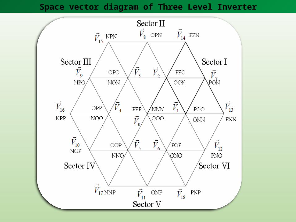
Space vector diagram of Three Level Inverter

Space vector diagram of Three Level Inverter
To calculate the dwell time of space vectors, the space vector diagram can be divided into six triangle sectors ( - Ⅰ Ⅵ)
Each sector is divided into four triangles (1-4)`
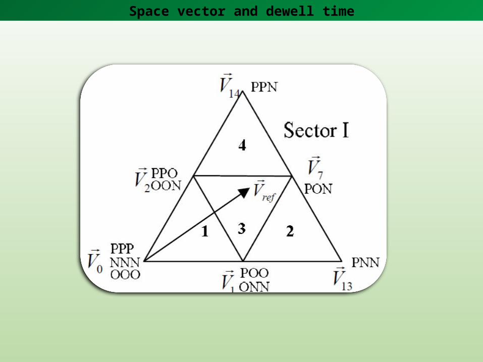
In the three-level NPC inverter, the reference vector 𝑉𝑟𝑒𝑓ሬሬሬሬሬሬሬሬԦ can be synthesized by the nearest three space vectors based on the volt-second balancing principle
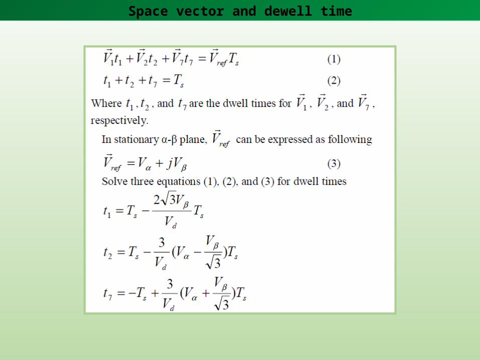
If 𝑉𝑟𝑒𝑓ሬሬሬሬሬሬሬሬԦ falls into region 3 of sector I as shown in Fig. The three nearest vectors are 𝑉1ሬሬሬԦ,𝑉2ሬሬሬԦ 𝑎𝑛𝑑 𝑉7ሬሬሬԦ . The following expressions can be gotten based on the volt-second balancing.
Space vector and dewell time
Space vector and dewell time
Space vector and dewell time

Space vector and dwell time
The dwell times can be calculated as above when reference vector is in other sectors.
DETERMINATION OF TRIANGLE LOCATION
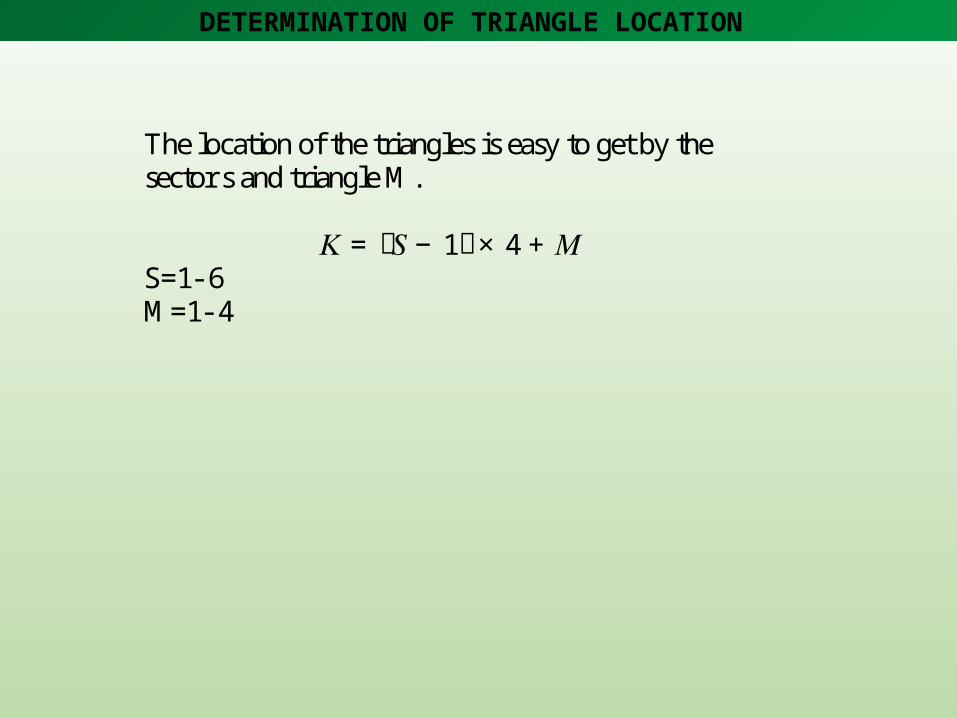
The location of the triangles is easy to get by the sector s and triangle M. 𝐾= ሺ𝑆− 1ሻ× 4+ 𝑀 S=1- 6 M=1- 4

Space vector and dwell time

Space vector and dwell time
Consideration for switching sequence
The neutral point voltage varies with the switching states of the NPC inverter, so the switching sequencing should be taken into account to control the neutral point voltage.
When the reference vector falls into different regions, there are two cases for the selected three vectors.
One is that there are two small vectors among the three vectors, such as in region 1, 3;
the other is that there is only one small vector, such as in region 2, 4. The switching sequencing is different for these two cases.

Consideration for switching sequence
In region 1, switching sequence 𝑉1𝑁ሬሬሬሬሬሬԦ− 𝑉2𝑁ሬሬሬሬሬሬԦ− 𝑉0ሬሬሬԦ− 𝑉1𝑃ሬሬሬሬሬሬԦ− 𝑉0ሬሬሬԦ− 𝑉2𝑁ሬሬሬሬሬሬԦ− 𝑉1𝑁ሬሬሬሬሬሬԦ In region 2, switching sequence 𝑉1𝑁ሬሬሬሬሬሬԦ− 𝑉13ሬሬሬሬሬሬԦ− 𝑉7ሬሬሬԦ− 𝑉1𝑃ሬሬሬሬሬሬԦ− 𝑉7ሬሬሬԦ− 𝑉13ሬሬሬሬሬሬԦ− 𝑉1𝑁ሬሬሬሬሬሬԦ
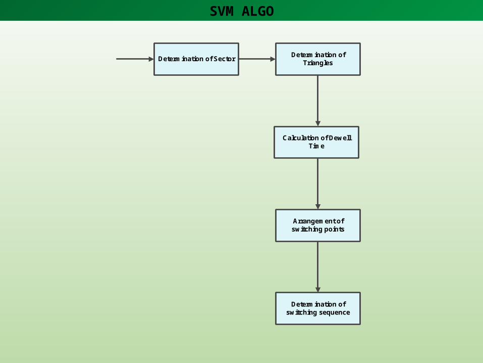
SVM ALGO
Determination of Sector Determination of Triangles
Calculation of Dewell Time
Arrangement of switching points
Determination of switching sequence

DETERMINATION OF SECTORS
Taking input and finding sector
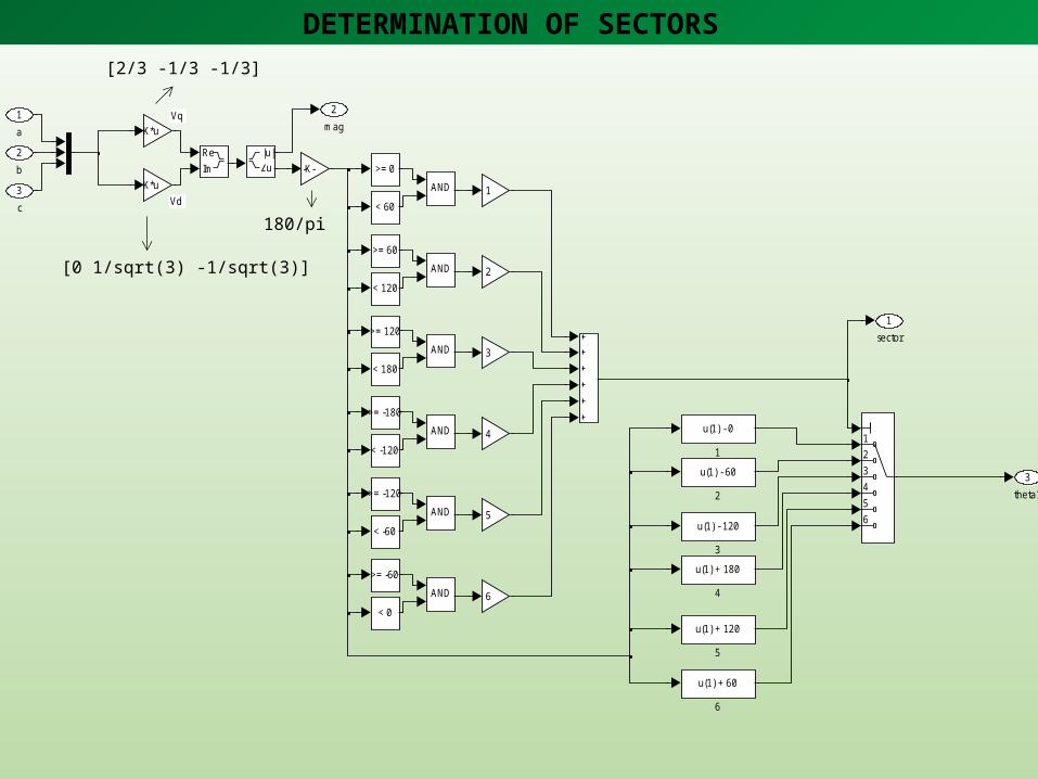
DETERMINATION OF SECTORS
Vq
Vd
3theta1
2mag
1sector
ReIm
123456
AND
AND
AND
AND
AND
AND
6
5
4
3
2
1
-K-K*u
K*u
|u|u
< -60
>= -120
< -120
>= -180
< 180
>= 120
< 120
>= 60
< 0
>= -60
< 60
>= 0
u(1) + 60
6
u(1) + 120
5
u(1) + 180
4
u(1) - 120
3
u(1) - 60
2
u(1) - 0
1
3
c
2b
1
a
[2/3 -1/3 -1/3]
[0 1/sqrt(3) -1/sqrt(3)]
180/pi
DETERMINATION OF TRIANGLES
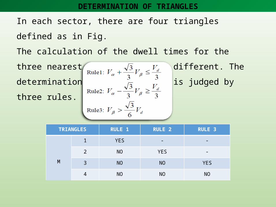
In each sector, there are four triangles defined as in Fig.
The calculation of the dwell times for the three nearest space vectors is
different. The determination of the triangles is judged by three rules.
TRIANGLES RULE 1 RULE 2 RULE 3
M
1 YES - -
2 NO YES -
3 NO NO YES
4 NO NO NO

DETERMINATION OF TRIANGLES
k2k1
V_beta_i
V_alfa_i
V_beta
V_alfa
k2
k1
3Vd0
2Vq0
1trngl
-K-
sqrt(3)/2
-K-
sqrt(3)
1
0.5
-C-11
1
u(1)*u(1) + 2*u(2)
k1*k1 + 2*k2
u(1)*sin(u(2)*pi/180)
V_beta
u(1)*cos(u(2)*pi/180)
V_alfaI n
S S/H >
1
2
rem
rem
-K-
2/sqrt(3)
-K-
1/sqrt(3)
0.5
0.53S/H pulse
2theta1
1mag
Trngl
Vq0
Vd0
Ts-pulse
s/w state selector
state selector
Discrete,Ts = 1e-005 s.
powergui
phase votage
phase current
0.55
m
mag
theta1
S/H pulse
trngl
Vq0
Vd0
local vector gen.
line voltage
sector
trngl
s/w state selector
gating signals
gating signal generator
gm
CE
ga9
gm
CE
ga8
gm
CE
ga7
gm
CE
ga6
gm
CE
ga5
gm
CE
ga4
gm
CE
ga3
gm
CE
ga2
gm
CE
ga12
gm
CE
ga11
gm
CE
ga10
gm
CE
ga1
abc
fourier
pi/2
delta
c phase
b phase
a
b
c
sector
mag
theta1
abc -> mag + local theta1
a phase
v+-
v+-
v+-
v+ -
v+ -
v+ -
f(u)
Vc_ref
f(u)
Vb_ref
f(u)
Va_ref
Scope3
Scope1
[gc2]
Goto9
[gc1]
Goto8
[gb4]
Goto7
[gb3]
Goto6
[gb2]
Goto5
[gb1]
Goto4
[ga4]
Goto3
[ga3]
Goto2
[gc4]
Goto11
[gc3]
Goto10
[ga2]
Goto1
[ga1]
Goto
2
[gc2]
[gc1]
[gb4]
[gb3]
[gb2]
[gb1]
[ga4]
[ga3]
[gc4]
[gc3]
[ga2]
[ga1]
ma
k
Db4
ma
k
Db3
ma
k
Db2
ma
k
Db1
ma
k
Da2
ma
k
Da1
i+ -
i+ -
i+ -
2 Constant<= 1e-005
100v2
100v1
-C-
0
-C-
-
[1x4]
+
Taking sector, Vref magnitude and angle, and finding triangle
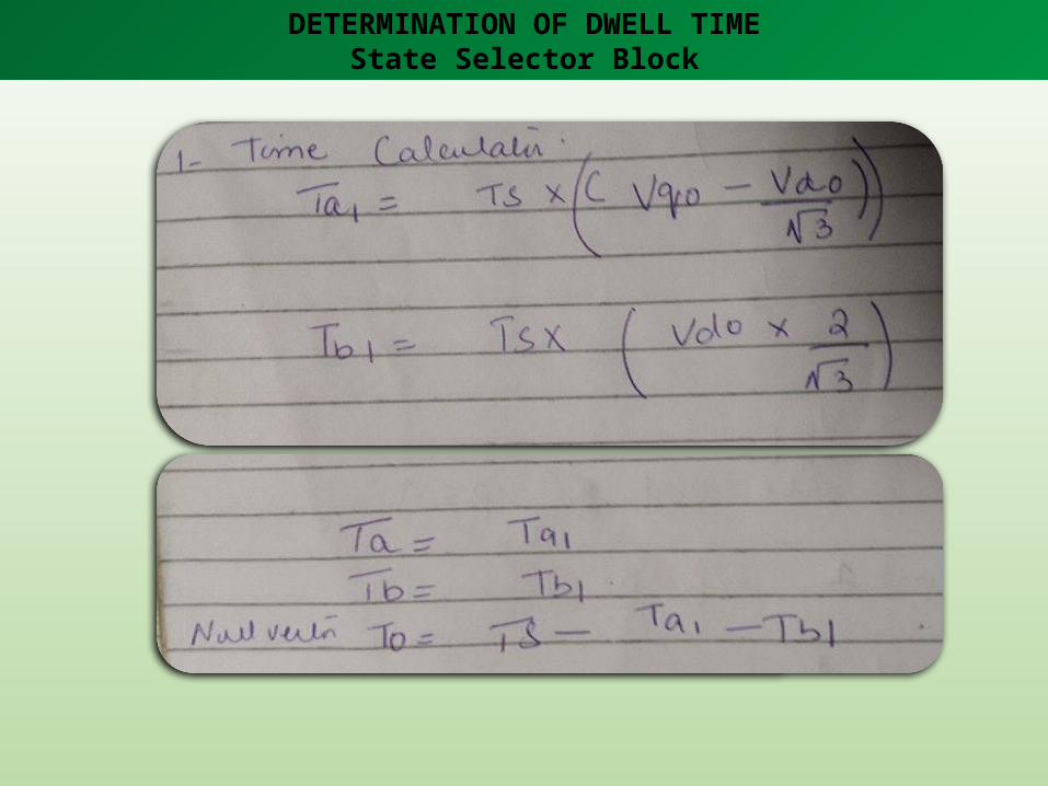
DETERMINATION OF DWELL TIMEState Selector Block

DETERMINATION OF DWELL TIME
1
s/w state selector
Vq0
Vd0
Ta
Tb
T0
vector -> time calculator
Ta
Tb
T0
Ts-pulse
trngl 3
trngl 3timer
Ta
Tb
T0
Ts-pulse
trngl 1
trngl 1timer
Ta
Tb
T0
Ts-pulse
trngl 0
trngl 0timer
Ta
Tb
T0
Ts-pulse
trngl 2
trgnl 2timer
1
Scope2
Scope1
1
2
3
4
4Ts-pulse
3
Vd0
2Vq0
1Trngl
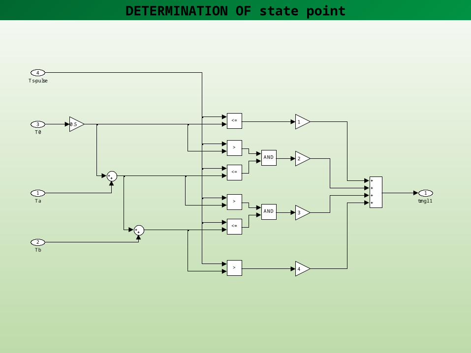
DETERMINATION OF state point
1trngl 1
>
<=
>
<=
>
<=
AND
AND
4
3
2
10.5
4
Ts-pulse
3T0
2Tb
1Ta
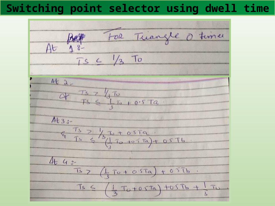
Switching point selector using dwell time
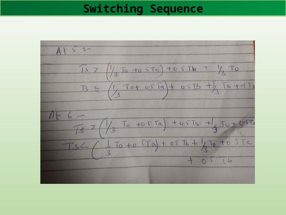
Switching Sequence

Switching point selector using dwell time
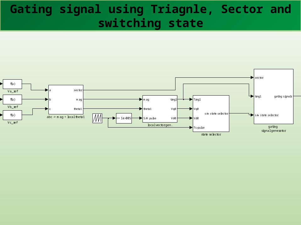
Gating signal using Triagnle, Sector and switching state
Trngl
Vq0
Vd0
Ts-pulse
s/w state selector
state selector
Discrete,Ts = 1e-005 s.
powergui
phase votage
phase current
0.55
m
mag
theta1
S/H pulse
trngl
Vq0
Vd0
local vector gen.
line voltage
sector
trngl
s/w state selector
gating signals
gating signal generator
gm
CE
ga9
gm
CE
ga8
gm
CE
ga7
gm
CE
ga6
gm
CE
ga5
gm
CE
ga4
gm
CE
ga3
gm
CE
ga2
gm
CE
ga12
gm
CE
ga11
gm
CE
ga10
gm
CE
ga1
abc
fourier
pi/2
delta
c phase
b phase
a
b
c
sector
mag
theta1
abc -> mag + local theta1
a phase
v+-
v+-
v+-
v+ -
v+ -
v+ -
f(u)
Vc_ref
f(u)
Vb_ref
f(u)
Va_ref
Scope3
Scope1
[gc2]
Goto9
[gc1]
Goto8
[gb4]
Goto7
[gb3]
Goto6
[gb2]
Goto5
[gb1]
Goto4
[ga4]
Goto3
[ga3]
Goto2
[gc4]
Goto11
[gc3]
Goto10
[ga2]
Goto1
[ga1]
Goto
2
[gc2]
[gc1]
[gb4]
[gb3]
[gb2]
[gb1]
[ga4]
[ga3]
[gc4]
[gc3]
[ga2]
[ga1]
ma
k
Db4
ma
k
Db3
ma
k
Db2
ma
k
Db1
ma
k
Da2
ma
k
Da1
i+ -
i+ -
i+ -
2 Constant<= 1e-005
100v2
100v1
-C-
0
-C-
-
[1x4]
+
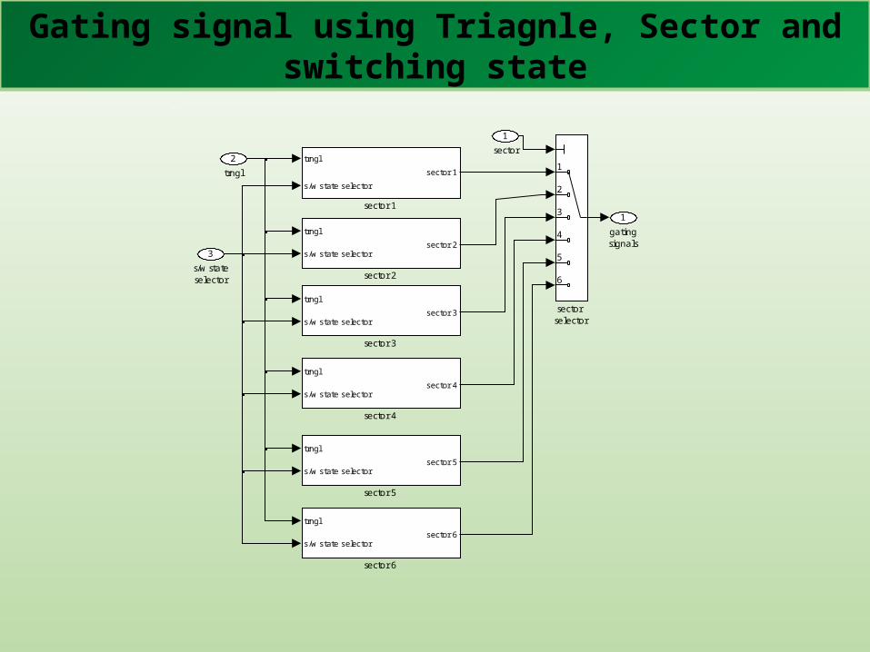
Gating signal using Triagnle, Sector and switching state
1gatingsignals
trngl
s/w state selectorsector 6
sector 6
trngl
s/w state selectorsector 5
sector 5
trngl
s/w state selectorsector 4
sector 4
trngl
s/w state selectorsector 3
sector 3
trngl
s/w state selectorsector 2
sector 2
trngl
s/w state selector
sector 1
sector 1
1
2
3
4
5
6
sector selector
3s/w stateselector
2trngl
1sector

Gating signal using Triagnle, Sector and switching state
1sector 1
s/w state selector trngl 3 data
trngl 3
s/w state selector trngl 2
trngl 2
s/w state selector trngl 1 data
trngl 1
s/w state selector trngl 0 data
trngl 0
1
2
3
4
trnglselector
1
2s/w stateselector
1trngl
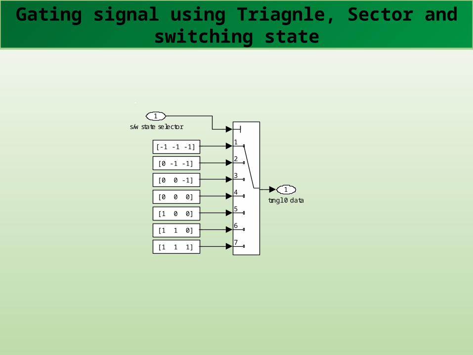
Gating signal using Triagnle, Sector and switching state
1trngl 0 data
[1 0 0]
[-1 -1 -1]
[1 1 1]
[1 1 0]
[0 0 0]
[0 0 -1]
[0 -1 -1]
1
2
3
4
5
6
7
1s/w state selector
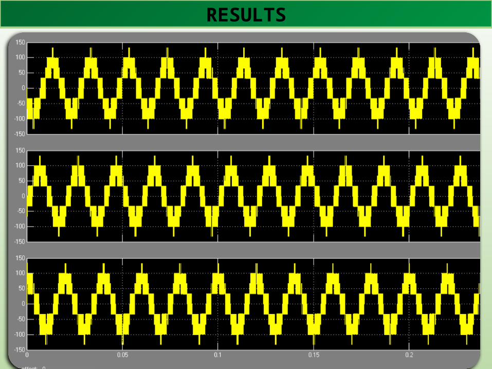
RESULTS

RESULTS

FOR 9-LEVEL

FOR 9-LEVEL
Space vectors in the Cartesian coordinate system (sector I).

FOR 9-LEVEL
To reduce the voltage harmonic distortion, the reference voltage Vref can be synthesized by the three nearest vectors. With V* lying in ∆𝐸𝐹𝐺, the reference voltage can be approximated by vectors
𝑉ሬԦ𝐸 = 72 + 𝑗ξ32 𝑉ሬԦ𝐹 = 3 + 𝑗ξ3 𝑉ሬԦ𝐺 = 4 + 𝑗ξ3
These vectors are converted to 𝛼𝛽− 𝑓𝑟𝑎𝑚𝑒.

FOR 9-LEVEL
Space vectors in the 600 coordinate system (sector I).
Each Sector has:
36 triangles
Total triangles
36*6=216
FOR 9-LEVEL
Switching sequence is difficult to determine.
Large, small Alternation methods as discussed previously becomes
complex in this case.


