8
SW Pad
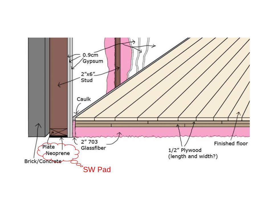
SW Pad

WIC

HD

ND

MASON INDUSTRIES, INC.350 Rabro Drive,Hauppauge, NY 11788 • 631/348-0282 • FAX 631/348-02792101 W. Crescent Ave., Suite D, Anaheim, CA 92801 • 714/535-2727 • FAX 714/535-5738Email [email protected] or [email protected] • Website www.Mason-Ind.com
Tm2088/02Printedin U.S.A.
15% DEFLECTIONLoad per Load per
DUROMETER 2” x 2” 50x50mmSquare Square
(lbs) (kgs)
30 80 3540 120 53
Standard 50 180 8060 240 10570 360 158
SUPER WLOAD RATINGS PER SQUARE
Pads can be used to reduce noise, high frequency vibrationand impact from typical machines as follows:
• Chillers
• Compressors
• HVAC Units
• Vent Sets
• Pumps
• Motor Generators
• Transformers
• Diesel Generators
• Punch Presses
• Lathes
• Saws
• Power Presses
• Drill Presses
Super W Pads should be used in full squares. Select theminimum number of squares required and design pad tothe most convenient square or rectangle. The use ofadditional squares results in more conservative loading.
British Units Example–Load is 980 lbs. 50 Duro capacity is 180 lbs.980/180 = 5.44 squares (Use 6 square modules).Pad may be 2 modules x 3 modules (4” x 6”)
or 1 module x 6 modules (2” x 12”)
Metric Units Example–Load is 5000 kgs. 50 Duro capacity is 80 kgs.5000/80 = 62.5 squares (minimum).Pad may be 8 modules x 8 modules (400 x 400mm)or 7 modules x 10 modules (350 x 500mm)or 6 modules x 11 modules (300 x 550mm) etc.
PADS MAY BE STACKED WITH16 GAUGE (1.6MM) SHIMSBETWEEN LAYERS FORINCREASED DEFLECTION.
Size Max. LoadType (inches) (mm) (lbs) (kgs)
10 x 12 x 11⁄4 250 x 300 x 32 6000 272210 x 10 x 11⁄4 250 x 250 x 32 5000 2268
WMSW- 8 x 8 x 11⁄4 200 x 200 x 32 3200 14526 x 6 x 11⁄4 150 x 150 x 32 1800 8166 x 4 x 11⁄4 150 x 100 x 32 1200 544
10 x 12 x 1 250 x 300 x 25 6000 272210 x 10 x 1 250 x 250 x 25 5000 2268
MBSW- 8 x 8 x 1 200 x 200 x 25 3200 14526 x 6 x 1 150 x 150 x 25 1800 8166 x 4 x 1 150 x 100 x 25 1200 544
THROUGHHOLE
FRICTION PADON TOP
MBSW
When there is a concentrated load because of a small leg on aheavy machine or a formed sheet metal leg without a bottomsurface, you can always cut a pad to size and cement your ownsteel plate on top. Usually it is more convenient to buy them, so weoffer two types. The WMSW has the cemented steel plate
sandwiched between a super waffle pad on the bottom and a 1/4”friction pad on the top. No bolting required. The MBSW replaces thefriction pad on top with a 3/4” diameter center hole for boltingthrough. We provide a 3/4” neoprene isolation washer cemented toa steel washer as well.
WMSW
WMSW and MBSW PAD ASSEMBLIES
Special Sizes on Request

Tm2055/02Printedin U.S.A.
SPACE SAVINGTYPE W NEOPRENEPAD INTERLOCKINGCLIP (SWAY BRACE)
MASON INDUSTRIES, Inc.Manufacturers of Vibration Control Products
350 Rabro Drive 2101 W. Crescent Ave., Suite DHauppauge, NY 11788 Anaheim, CA 92801
631/348-0282 714/535-2727FAX 631/348-0279 FAX 714/535-5738
[email protected] [email protected] www.MasonAnaheim.com
TYPE
WICDATA SHEET DS-402-1 B
STANDARD STEELSTUDDING END WIC Brace with 5/16"(8mm) Bolt for MetalStuds (Bolt by Others)
8"(203mm)Typical
STANDARDCONCRETEBLOCK END WIC Brace with 5/16"(8mm) Diameter Rodwith 2"(51mm) I.D.Hooked End forMasonry Walls(Hook by Others)
Thickness Material (lbs/ft2)(in)(mm) (kg/m2)
4 102 35 1758 203 Brick 75 365
12 305 115 560
4 102 Heavy 35 1756 152 Aggregate 50 2458 203 Hollow 58 285
12 305 Concrete Block 90 440
4 102 Poured 48 2356 152 Concrete 72 3508 203 Masonry 96 470
12 305 144 705
Thickness Material (lbs/ft2)(in)(mm) (kg/m2)
4 102 Steel Studding Alone 1.5 7.52x4 51x102 Wood Studding Alone 2.0 10
1/2 13 2.1 105/8 16 Gypsum Board 2.7 133/4 19 3.2 16
1 25 Cement Plaster 10.0 501 25 Gypsum Plaster 5.0 25
- Metal Lathe 0.5 2.5- Gypsum Lathing Board 2.0 10
COMMON WALL WEIGHTS
1. Sway braces prevent buckling or overturning of tall or long walls.2. Buckling forces are extremely small when braces are reasonably
spaced both horizontally and vertically as the brace spacingmaintains a very low l/r column ratio.
3. Our general recommendation is spacing on four foot centers bothhorizontally and vertically.
4. The maximum axial restraint rating is approximately 33% of themaximum assigned wall weight and extremely conservative.
5. Vertical resistance information is provided for checking embedmentrequirements in walls and shear or pullout forces on both ends of thesway braces. Sway braces are not to be used for vertical supports.
6. Response frequency is a function of the attached mass and thedynamic stiffness in the direction of vibration. The 15 Hz responseis normally lower and more desirable than what is usuallyspecified. Heavier weight assignments than the specified minimumwill lower the response frequency by the square root of the ratio ofthe minimum weight to the assigned value multiplied by 15 Hz.Lighter loads will increase the frequency by the same proportion. EXAMPLE: Steel stud wall with 2 layers of 3/4 inch gypsum board
weighing 7.9 lbs. per sq/ft. Sway braces on 4 footcenters both ways.Assigned Weight = 16 x 7.9 = 126 lbs.WIC-1 Selection (Maximum 250 lbs)Frequency = 15Hz x 126/250 = 10.65 Hz
Rated Horizontal Restraint Maximum Minimum& Deflection if Stressed Assigned Assigned
Wall Weight toType & Load Defl Weight Establish
Size (lb)(kg) (in)(mm) (lb)(kg) 15Hz(lb)(kg)
WIC-1 90 41 0.05 1.3 250 113 50 23
WIC-2 260 118 0.05 1.3 500 227 100 45
TYPE WIC LOAD RATINGS
Type & B HoleSize A Diameter
WIC-1 1 25 3/8 10
WIC-2 2 51 3/8 10
TYPE WIC DIMENSIONS (in mm)
33/4”(95mm)
11/2”(38mm)
11/2”(38mm) 4”
(102mm)
3”(76mm)
A
B
SPECIAL DIMENSIONSON REQUEST
MATERIAL:
Standard 40 Durometer5/16”(8mm) Neoprene Waffle Pad

H
D
LRP
Double DeflectionNeoprene Element,with a projecting bushingto prevent steel to steelcontact.
Upper & Lower Rods,by Others
W
TYPE HD RATINGS
Size Range Deflection(Color Mark) Durometer [lbs] [in]
Rated Max.Capacity Rated
HD-Green 40 Up to 35 0.20 HD-White 60 35 - 75 0.20 HD-A-Black 30 Up to 45 0.35 HD-A-Green 40 30 - 75 0.35 HD-A-Red 50 60 - 125 0.35 HD-B-Red 50 Up to 235 0.40 HD-B-White 60 180 - 380 0.40 HD-B-Yellow 70 320 - 650 0.40 HD-BS-Blue 70 500 - 1000 0.40 HD-CS-Blue 70 1000 - 2100 0.40 HD-DS-Blue 70 2100 - 4200 0.40Hanger elements have straight line deflection curves.
LRP - Lower Rod PenetrationMRD - Maximum Rod Diameter
TYPE HD DIMENSIONS (inches)Size D H W LRP MRD
HD 1 /4 2 /4 1 /8 1 /4 /8 HD-A 2 2 /4 2 /4 2 /4 /2 HD-B 3 /4 4 /2 4 /4 3 /4 HD-BS 3 /4 4 /2 4 /4 3 /4 HD-CS 3 /4 5 4 /4 3 /4 /8 HD-DS 4 6 /4 4 /4 3 /4 /8
3
111
1311
1
711113
11
11
313377
DWN : CHKD: DATE : DWG NO. :FORM S-600-6b 01/98
CERTIFICATION DATA inch SPECIFIED DEFLECTION
TAG : 1 : 6 :
UNIT : 2 : 7 :
PLAN VIEW OF HANGER LOCATION :
3 : 8 :
4 : 9 :
5 : 10 :
Material for One Set : Sets Required
CERTIFIED FORJOB NAME :CUSTOMER :CUSTOMER P.O. :MASON M.I. :DWG. NO. :
TYPE
HDDouble Deflection
Neoprene Hangers
MASON INDUSTRIES, Inc.Manufacturers of Vibration Control Products
350 Rabro DriveHauppauge, NY 11788
631/348-0282FAX 631/348-0279
2101 W. Crescent Ave., Suite DAnaheim, CA 92801
714/535-2727FAX 714/535-5738
NY Mailing Address: PO Box 410, Smithtown, NY 11787

Rather than bolting two mountings together, we decided to do thisproperly and started manufacturing two mountingsusing the same base and top plates. The shorterType N for single deflection; the taller ND,double deflection. We include capscrews andwashers, to eliminate the nuisance of ourcustomers finding proper bolts.
Since rubber mountings are inexpensive, we nowsell only the ND, so there is always the benefit of the better product.
It is not necessary to bolt these mountings to the floor on mostinstallations. They can be used under flat bases that have no boltholes in much the same manner as rubber pads. When theequipment has a flush drain pan or tank on the bottom, the mountingmay be inverted so that the rectangular rubbercovered steel base plate provides supportover a large area.
Size D H L T W BC CS MBD
ND-A 13/16 30 11/2 38 33/16 81 3/16 5 15/8 41 23/8 60 5/16 -18 x 3/4" x 19 5/16 8ND-B 13/4 44 17/8 48 37/8 98 1/4 6 25/16 59 3 76 3/8 -16 x 1" x 25 5/16 8ND-C 29/16 65 23/4 70 51/2 140 1/4 6 35/16 84 41/8 105 1/2 -13 x 1" x 25 1/2 13ND-D 33/8 86 23/4 70 61/4 159 5/16 8 4 102 5 127 1/2 -13 x 1" x 25 1/2 13ND-DS 33/8 86 23/4 70 61/4 159 5/16 8 4 102 5 127 1/2 -13 x 1" x 25 1/2 13
TYPE ND DIMENSIONS (inches mm)
H
T
D
BC L
W
"CS" CAP SCREW
"MBD"MAXIMUMBOLTDIAMETER
Top & Bottom–Steel PlatesNeoprene coveredto prevent corrosionand provide friction
Rated MaxSize Capacity Rated
(Color Duro- Range DeflMark) meter (Ibs) (kgs) (in) (mm)
ND-A-Black 30 15-45 7-20ND-A-Green 40 30-75 13-34 0.35 99ND-A-Red 50 60-125 27-57
ND-B-Black 30 50-100 23-45ND-B-Green 40 75-150 34-68ND-B-Red 50 110-235 50-107 0.40 10ND-B-White 60 180-380 82-172ND-B-Yellow 70 300-600 136-272
ND-C-Green 40 140-260 64-118ND-C-Red 50 200-400 91-181 0.50 13ND-C-White 60 310-600 141-272ND-C-Yellow 70 520-1000 236-454
ND-D-Yellow 70 1060-2100 481-953 0.50 13
ND-DS-Yellow 70 2200-4300 998-1950 0.50 13
TYPE ND RATINGS
Mounts have straight line deflection curves.
ND Mounts MASON INDUSTRIES
Inverted
DoubleDeflection ND Mount
Standard mountings are furnished in oilresistant Neoprene. Since we mold theseproducts ourselves, bridge bearing qualityNeoprene, Natural Rubber or otherelastomers are readily available to meetyour requirements.
SPECIFICATION
Neoprene mountings shall have a minimumstatic deflection of 0.35” (9mm). All metalsurfaces shall be Neoprene covered toprevent corrosion and have friction pads,both top and bottom. Bolt holes shall beprovided on the bottom and a tapped holewith capscrew and washer on top.Mountings shall be Type ND, asmanufactured by Mason Industries, Inc.


![1. Distinguish between Sway and Non sway type … IV 1. Distinguish between Sway and Non – sway type problems?[M/J-15] Because of sway, there will be rotations in the vertical members](https://static.documents.pub/doc/80x56/5af80c3b7f8b9a5f588c535c/1-distinguish-between-sway-and-non-sway-type-iv-1-distinguish-between-sway.jpg)


