12
Swing Door Service Installation Packet Do Not Discard Leave with Homeowner Part No. 7500026

Swing Door Service
Installation Packet
Do Not DiscardLeave with Homeowner
Part No. 7500026

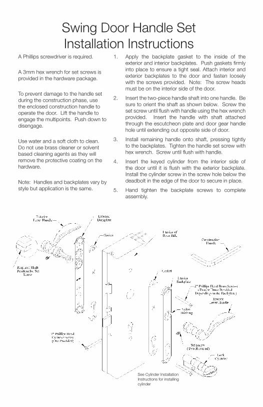
Swing Door Handle SetInstallation Instructions
1. Apply the backplate gasket to the inside of the exterior and interior backplates. Push gaskets firmly into place to ensure a tight seal. Attach interior and exterior backplates to the door and fasten loosely with the screws provided. Note: The screw heads must be on the interior side of the door.
2. Insert the two-piece handle shaft into one handle. Be sure to orient the shaft as shown below. Screw the set screw until flush with handle using the hex wrench provided. Insert the handle with shaft attached through the escutcheon plate and door gear handle hole until extending out opposite side of door.
3. Install remaining handle onto shaft, pressing tightly to the backplates. Tighten the handle set screw with hex wrench. Screw until flush with handle.
4. Insert the keyed cylinder from the interior side of the door until it is flush with the exterior backplate. Install the cylinder screw in the screw hole below the deadbolt in the edge of the door to secure in place.
5. Hand tighten the backplate screws to complete assembly.
A Phillips screwdriver is required.
A 3mm hex wrench for set screws is provided in the hardware package.
To prevent damage to the handle set during the construction phase, use the enclosed construction handle to operate the door. Lift the handle to engage the multipoints. Push down to disengage.
Use water and a soft cloth to clean. Do not use brass cleaner or solvent based cleaning agents as they will remove the protective coating on the hardware.
Note: Handles and backplates vary by style but application is the same.
See Cylinder Installation Instructions for installing cylinder

Handles and backplates vary in style.
Sw
ing D
oo
rH
andle O
peratio
n Instructions
To lock manual system
, lift handle to engage m
ultipoints prior to engaging deadbolt.
Use key or thum
bturn to engage deadbolt.
If deadbolt will not fully engaged,
manually engage system
by lifting handle prior to engaging deadbolt.
To open, disengage deadbolt w
ith key or thumbturn, push
handle down to stop and then
open door.
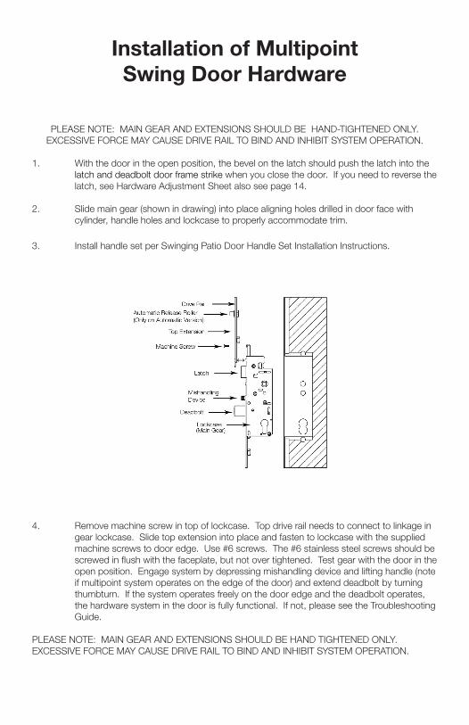
PLEASE NOTE: MAIN GEAR AND EXTENSIONS SHOULD BE HAND-TIGHTENED ONLY. EXCESSIVE FORCE MAY CAUSE DRIVE RAIL TO BIND AND INHIBIT SYSTEM OPERATION.
1. With the door in the open position, the bevel on the latch should push the latch into the latch and deadbolt door frame strike when you close the door. If you need to reverse the latch, see Hardware Adjustment Sheet also see page 14.
2. Slide main gear (shown in drawing) into place aligning holes drilled in door face with cylinder, handle holes and lockcase to properly accommodate trim.
3. Install handle set per Swinging Patio Door Handle Set Installation Instructions.
4. Remove machine screw in top of lockcase. Top drive rail needs to connect to linkage in gear lockcase. Slide top extension into place and fasten to lockcase with the supplied machine screws to door edge. Use #6 screws. The #6 stainless steel screws should be screwed in flush with the faceplate, but not over tightened. Test gear with the door in the open position. Engage system by depressing mishandling device and lifting handle (note if multipoint system operates on the edge of the door) and extend deadbolt by turning thumbturn. If the system operates freely on the door edge and the deadbolt operates, the hardware system in the door is fully functional. If not, please see the Troubleshooting Guide.
PLEASE NOTE: MAIN GEAR AND EXTENSIONS SHOULD BE HAND TIGHTENED ONLY. EXCESSIVE FORCE MAY CAUSE DRIVE RAIL TO BIND AND INHIBIT SYSTEM OPERATION.
Installation of MultipointSwing Door Hardware

HLS9000 Multipoint Hardware System Maintenance and Terminology
Note:All options are shown for the sake of terminology.The gear system you have will NOT contain all of the components as shown in the diagram below.
TERMINOLOGY:
1. Top Shootbolt2. Bottom Shootbolt3. Deadbolt4. Mishandling Device5. Latch Bolt6. Cylinder Hole7. Handle Hole8. Lockcase9. Drive Rail10. Faceplate11. Screw Support12. Tongue13. Top Extension Phillips
Machine Screw
1. Trim Maintenance:DO NOT SUBJECT TRIM TO ABRASIVE OR SOLVENT-BASED CLEANING MATERIALS OR EARLY TARNISHING WILL RESULT!Use water to clean and a soft cloth. Do not use brass cleaner as it will remove the protective coating.
2. Profile Cylinder:
Cylinders are available in rekeyable Schlage C version. Key blanks are available at most hardware stores

Be certain door is square in frame before adjusting other hardware. With the door in the open position, engage system by lifting handle and extend deadbolt by turning thumb turn. If the system operates on the door edge and the deadbolt operates, the hardware system is fully functional.
1. SYSTEM WILL NOT OPERATE WHEN YOU LIFT THE HANDLE
Probable Cause: Improper installation of handle set.Solution: Remove handle and reinstall. See Handle Set Installation Instructions.
2. SYSTEM OPERATES IN THE OPEN POSITION WHEN YOU LIFT THE HANDLE BUT
NOT IN THE CLOSED POSITION WITH THE DOOR SHUT
Probable Cause: Relationship of door in the frame.Solution: Check to make sure the door is square in the frame.
3. LOCKING POINTS WILL NOT ENGAGE WITH DOOR SHUT
Probable Cause: Deadbolt is not fully extending.Solution: Clear away anything blocking travel of deadbolt (insulation, wood, etc.).
4. DEADBOLT WILL NOT FULLY ENGAGE
Probable Cause: Locking points are not fully engaged. System design does not permit deadbolt operation unless locking points are fully engaged. Solution: Check system again for binding problems. Confirm deadbolt extends fully into strike. Check to confirm locking points are correctly engaging strikes on the frame.
5. THUMBTURN OR KEY WILL NOT TURN
Probable Cause: Backplates may not be on straight.Solution: Confirm that inside and outside holes line up with lockcase. Loosen backplate screws ½ turn.
Troubleshooting Guide Multipoint Swing Door Hardware

6. HANDLE SAGS OR RETURNS SLOWLY
Probable Cause: Cladding or wood in the hole is interfering with shaft.Solution: Check to see if machined holes line up with screw and handle holes. May need to file or drill hole slightly larger.
7. SET SCREWS WILL NOT GO INTO HANDLE COMPLETELY Probable Cause: Shaft is not assembled properly.
Solution: Remove handle to see how shaft is assembled. See Handle Set Installation Instructions for proper assembly and position of shaft.
8. BOTTOM LOCKING POINT MOVES BUT TOP LOCKING POINT DOES NOT
Probable Cause: Top extension drive rail is not connected at the lockcase.Solution: Remove screws used to attach top extension to the door and the machine screw that attaches it to the lockcase, and remove top extension. Place the end of the drive rail (the “L” shape) in the lockcase above the latchbolt, as you slide the top extension into the door. Fasten with a screw at the lockcase and the one up higher. Operate the gear to make sure it works. Then finish installing the rest of the screws.
9. IF DOOR HAS PLAY OR IS NOT SEALING CORRECTLY
Probable Cause: Unit is not adjusted properly.Solution: Bend tab on strike.Solution: If available adjust Hinge
10. KEY DOES NOT WORK IN CYLINDER
Probable Cause: Cylinder was rekeyed incorrectly.Solution: Check with Builder or Installer to see if cylinder was rekeyed to match other doors in the house. If so, return to locksmith to rekey properly.

Hardware Modification Instruction Sheet
Reversing Mishandling Device in Field:
1. Remove sticker2. Remove shipping clip3. Make sure
mishandling device is sloped the same as latch.
4. If not, pull out and spin180* to the same direction.
Reversing Mishandling Device in Factory:
1. Remove shipping clip2. Pull out mishandling
device to spin to slope the same as latch.
3. Push mishandling device in and snap shipping clip back in.
Shipping Clip for Mishandling Device
Attaching Top Extension
Reversing Latch
Pull and rotate latch 180* with hand and release back into
the lockcase.
Hook drive rail of top extension into gear linkage just above latch.

HOPPE Profile CylindersRekeying Instructions
Introduction
Steps to Rekey
Recommended Tools and Accessories
REMOVAL TOOL for PLASTIC INSERT
Part Number 2000899(for use with CES cylinders)
2 mm or 5/64” HEX WRENCH
(for use with non-logo cylinders)
Determine CORE PIN size with KEYING GAUGE
Remove one SET SCREW at a time using 2 mm HEX WRENCH as shown and tap out PINS and SPRING
HOPPE REKEY KITSSchlage® Pins, 30 cyl. capacity
- Part Number 3459001CES Pins, 10 cyl. capacity- Part Number 8785243
HOPPE KEY GAUGEPart Number 2070820
PLASTIC INSERTPart Number 8771719
(for use with CES cylinders)
3.
2.
1. Remove PLASTIC INSERT using REMOVAL TOOL as shown and tap out PINS and SPRINGS
OR
PLASTIC PLUG
SPRINGS
HOUSING (TOP) PINS
CORE (BOTTOM)
PINS
OR
• Insert desired CORE PIN into the appropriate cylinder pin hole. • Note: for cylinder designs featuring
six pin holes, the innermost hole (furthest from the key face) is left blank.
• Insert HOUSING PIN• Insert SPRING• Repeat until all PINS have been replaced
and install PLASTIC INSERT OR install SET SCREW and repeat until all PINS have been replaced.
SET SCREWS
SPRINGS
HOUSING (TOP) PINS
CORE (BOTTOM)
PINS
• If rekeying a CES cylinder with CES pins, use the CES pin number that corresponds with the measured key cut.
• If rekeying a CES cylinder with Schlage® pins, use the Schlage® pin number that is one less than the measured key cut. A key cut measuring 4 uses a #3 Schlage® pin.
• If rekeying a non-logo cylinder with Schlage® pins, then use the Schlage® pin number that corresponds with the measured key cut.
• If rekeying a non-logo cylinder with CES pins, use the CES pin number that is one higher than the measured key cut. A key cut measuring 4 uses a #5 CES pin.
• Rekeying should be done by a qualified locksmith.
• Cylinder designs vary. HOPPE supplies CES brand cylinders and non-logo cylinders.
• Cylinders feature Schlage® SC1 keyways and may be rekeyed using Schlage® rekey kits.
• Cylinders should be rekeyed to an existing Schlage® key whenever possible.
• The HOPPE key gauge measures key cuts 1 through 9 the same as a Schlage® key gauge.
1-888-485-4885www.us.hoppe.com

Tools required: Phillips head screw driver Hex wrench (provided) Ring wrench (provided) Pliers (recommended)
Installation: 1. Loosen set screw (C) on knob (D) using the hex wrench provided. Knob designs may vary from
design shown.2. Remove knob (D) from body of cylinder (B).3. Align drive tab (J) with the cylinder body to install the cylinder into the lock as shown by (G). If the
drive tab (J) cannot be rotated to this position, push the pin (E) down with the ring wrench (F) to disengage the stops and turn the cylinder shaft (B) until the drive tab (J) is aligned with the cylinder as shown by (G).
4. Holding the cylinder in this position, insert the cylinder body into the lock so the drive tab (J) is inside of the lock.
5. Rotate the shaft (B) (use pliers if necessary) so the top of the shaft (B) moves toward the edge of the door or insert the key (A) into the cylinder and rotate so the top of the key (A) moves towards the edge of the door (H). The shaft or key will rotate freely and will stop after approximately 120°. Do not force rotation. The dead bolt should not extend (exception: dead bolt will extend on single point gear). Confirm that one of the two set screw openings is positioned on the bottom of the shaft (B).
Warning: If the shaft (B) or key (A) is rotated the wrong direction, the cylinder will lock after approximately 120° and cannot be rotated in either direction. If this happens, push the pin (E) down with the ring wrench (F) included to disengage the stops and turn the shaft (b) or key (A) in the opposite direction until the dead bolt extends.
6. Attach knob (D) on shaft (B) as shown.7. Tighten set screw (C). Install cylinder screw (K) as shown.
Removal:1. Loosen and remove cylinder screw (K) and repeat steps 1-4 above.
Installation Instructions90-Degree Turn Cylinder
(A)(B)
(B)
(B)
(C)
(D)
(E)
(F)
(G)
(H)(H)
(J)
(K)
Aligned
Knob designs may vary from design shown.

Therma-Tru DoorsCustomer Service
1750 Indian Wood CircleMaumee, Ohio 43537
1-800-THERMA-TRU (843-7628)


![DOOR TO DOOR COLLECTION OF MSW IN CATALONIA · DOOR TO DOOR COLLECTION OF MSW IN CATALONIA ... Separate Collection Door to Door in Catalonia [1] DtD abandoned Municipalities DtD Door](https://static.documents.pub/doc/80x56/5fb98d88d1680979b16ece80/door-to-door-collection-of-msw-in-catalonia-door-to-door-collection-of-msw-in-catalonia.jpg)
