20
4 x 1 HDMI UHD Switcher with Fast Switching and Control System - # 15369 Operation Manual
| Date post: | 21-Aug-2018 |
| Category: |
Documents |
| Upload: | truongdung |
| View: | 221 times |
| Download: | 0 times |

4 x 1 HDMI UHD Switcher with Fast
Switching and Control System - # 15369
Operation Manual

IntroductionThis 4 by 1 HDMI UHD Switcher allows four HDMI sources to be routed to an HDMI display. The Fast Switching Technology greatly reduces the time required to swap between inputs. The Control System not only provides direct control but also indirect control interfaces for all your connected devices. Supporting traditional direct control systems like IR, Relay and DC and indirect control systems like IR Learning, RS-232, Telnet/WebGUI controls, it allows the user with PC or APP based control systems great flexibility over devices. The operation of the system can be easily managed through software application on PC/Laptop or APP on mobile devices, on-panel buttons, IR remote control, RS-232, Telnet or Ethernet protocols.
Applications• Showroom display & control• Educational demo & control• Home entertainment & security control
Features
• HDMI (with 3D & 4K2K supported) and HDCP compliant
• Supports HDTV resolutions up to 4Kx2K (3840×2160@24/25/30Hz & 50/60Hz with YUV420 or 4096×2160@24Hz & 50/60Hz with YUV420)
• Supports HDMI data rate from 300Mbps to 3Gbps and ‘Deep Color’ up to 1080p/36-bit
• Supports simultaneous audio outputs on both HDMI and analog R/L• HDMI inputs support ‘Standard’ and ‘Apple’ HDCP modes. Selecting
‘Apple mode guarantees the compatibility of Apple devices• Support RS-232, IR, Telnet and WebGUI controls• Supports four inputs control with voltage of 0~3.3v• Supports control system with 5 IR outputs, 4 Trigger inputs, 4 Relay
outputs and 2 COM ports• Supports COM port’s Baud rate from 4800~115200bps• Supports auto source detection with the latest input signal• Speaker supports LPCM 2CH
System
Requirements
Input source equipment such as DVD/Blu-ray player and output HD display/Monitor with HDMI cables. Control system input sources such as light, TV, power switch and etc... and PC/Laptop for output control.

Operation Controls and Front PanelFunctions
1. POWER Button and LED: Press this button to switch On or set the device to standby mode. The LEDwill illuminate in green when the device is power On and if it is switched to standby mode the LED will turn red.Note:For IP reset from Static to DHCP mode, press and hold the power button for 3 seconds while the device is ON and the LED will blink once.2. IR Window and LED: This IR Receiver receives the remote control signal from the package included remote control only and the LED will blink when IR signal is receiving.3. OPTICAL IN Button and LED: Press this button to select output audio from optical source and the LED will illuminate.4. HDMI IN Button and LEDs 1~4: Press this button to select an input from the input sources 1~4 and the LED will illuminate according to the selection.Note:For firmware update, press and hold this button then plug-in the AC power into the device and then the USB flash driver with updated firmware(s) inside.5. +/-: Press these buttons to adjust up/down the output audio sound. 6. MUTE Button and LED: Press this button to mute the SPEAKER output sound. The LED will illuminate when audio is set to mute either from front-panel’s mute button, IR, Telnet, WebGUI or RS-232 and when the input audio format is non-PCM the LED will be blinking. Press it again to unmute and the LED will switch off.Note:For restore back to factory default, press and hold this button then plug-in the AC power into the device.7. SYNC LED: This LED will illuminate when the input detected HDMI signal from source equipment.8. TRIGGER IN LED 1~4:

These LEDs will illuminate when IN connection obtain active low DC voltage of 0~0.5V which is also when signals has been triggered. Under normal operation, the voltage is about 3.3V.
Rear Panel
1. USB:
This slot is reserved for firmware update use only.2. CONTROL: Connect from PC/Laptop with active internet service for Telnet or WebGUI control with RJ-45 terminated cable.3. RS-232: Connect from PC/Laptop for RS-232 command sending to control the device.4. INFRARED OUT 1~5: Connect with IR Blaster for IR signal transmitting.5. HDMI IN: Connect from source equipment such as Blu-ray/DVD/PS3 players, Set-Top-Box or any HDMI equipped source device for input signal sending. Thisdevice has source auto-detection function from the latest input and when the latest input has been pulled out it will follow the number sequence. 6. HDMI OUT: Connect to HDMI TV/display or HD Amplifier for output image and or audio display.7. OPT. IN: This slot is to connect with audio source equipment such as Blu-ray/PS3 player for audio signal input through optical cable.8. COM 1~2: Connect from other devices that are to be controlled with 3.5mm terminal block cable for control through RS-232 commands.9. RELAY OUT R1~4: Connect with control device’s DC power such as curtain or projector screen.10. TRIGGER IN 1~4: Connect with event device’s signal lines such as window security alarm, door switch, and etc... for trigger signal sending back to Control System andor run the macro commands.

11. SPEAKER R/L:
These slots are to connect with analog speakers through banana jack cables for audio signal output from HDMI or Optical. Note:These slots only support LPMC 2CH signal, other signals will be mute automatically. 12. DC 24V: Connect the adaptor included in the package and connect to AC wall outlet for power supply.
Remote Control1. POWER: Press this button to switch On or set the device to standby mode.2. INPUT 1~4: Press these buttons once a time to select or switch input source.3. MUTE: Press this button to mute the SPEAKER output sound press it again to unmute.4. OPTICAL: Press this button to select audio from optical input source. 5. -/← VOL +/→: Press these buttons to move down/up the output speaker volume.
IR Pin Definitions
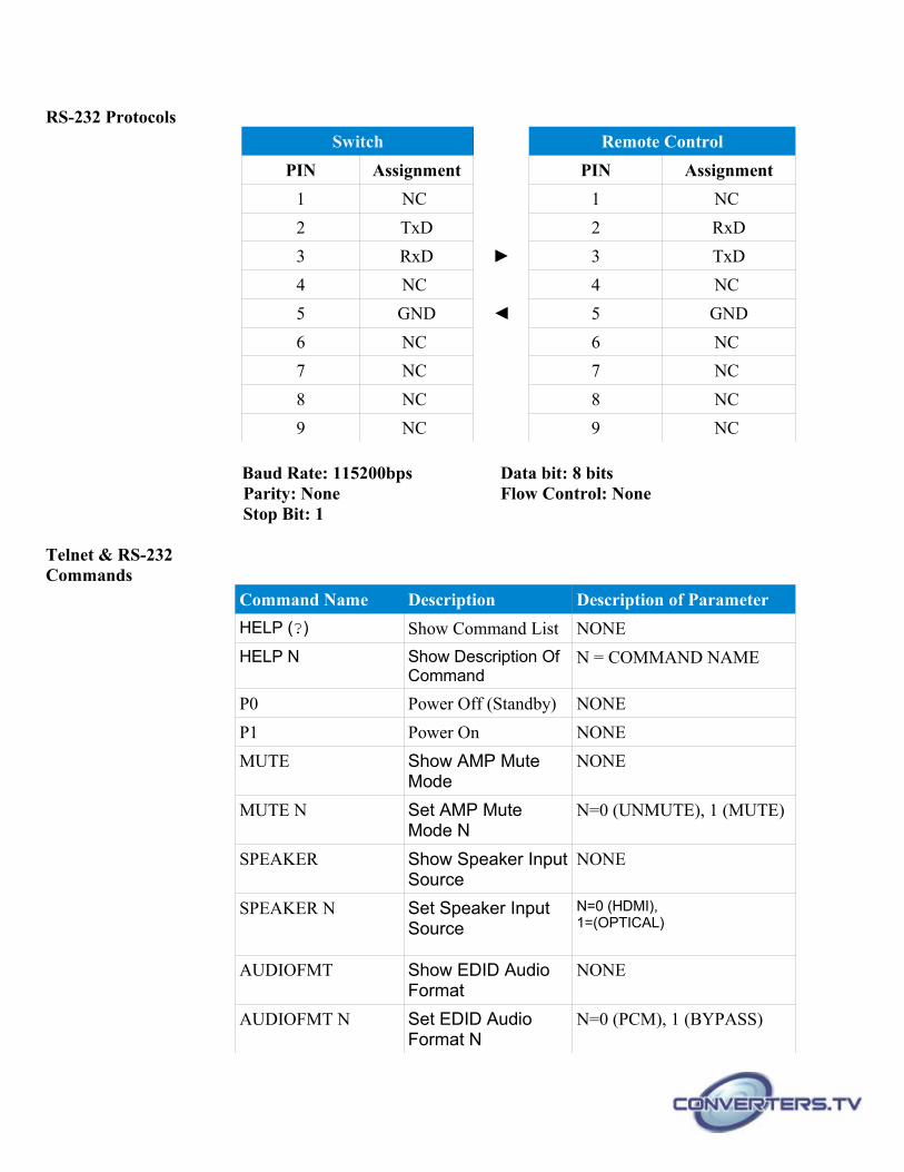
RS-232 ProtocolsSwitch Remote Control
PIN Assignment PIN Assignment
1 NC 1 NC
2 TxD 2 RxD
3 RxD 3 TxD
4 NC 4 NC
5 GND 5 GND
6 NC 6 NC
7 NC 7 NC
8 NC 8 NC
9 NC 9 NC
Baud Rate: 115200bps Data bit: 8 bitsParity: None Flow Control: NoneStop Bit: 1
Telnet & RS-232Commands
Command Name Description Description of Parameter
HELP (?) Show Command List NONE
HELP N Show Description Of Command
N = COMMAND NAME
P0 Power Off (Standby) NONE
P1 Power On NONE
MUTE Show AMP Mute Mode
NONE
MUTE N Set AMP Mute Mode N
N=0 (UNMUTE), 1 (MUTE)
SPEAKER Show Speaker InputSource
NONE
SPEAKER N Set Speaker Input Source
N=0 (HDMI), 1=(OPTICAL)
AUDIOFMT Show EDID Audio Format
NONE
AUDIOFMT N Set EDID Audio Format N
N=0 (PCM), 1 (BYPASS)

SOUNDSYS Show AMP Sound System
NONE
SOUNDSYS N Set AMP Sound System N
N=0 (STEREO), 1 (MONO)
VOL Show AMP Volume NONE
VOL N Set AMP Volume N N=0-100
A N Select Input N N=1-4*
IPGONFIG Display The CurrentIP Configure
NONE
SIPADDR XXX.XXX.XXX.XXX
Set Ethernet IP Address
XXX=0~255
SNETMASK XXX.XXX.XXX.XXX
Set Ethernet Net Mask
XXX=0~255
SGATEWAY XXX.XXX.XXX.XXX
Set Ethernet Gateway
XXX=0~255
HTTPPORT N Set Http Port Number N=0~65535
RSTIP IP Configuration Reset To <DHCP>
NONE
EDIDMODE Show EDID MODE NONE
EDIDMODE N Set EDID Mode N=0(Appoint), 1(All)
EDIDALL Set EDID Mode NONE
EDIDALL N Show EDID Mode Source For All
N=1-9**
EDIDIN Set EDID Mode Source For All
NONE
EDIDIN N1 Show Input N1EDID Source
N1=1-4*
EDIDIN N1 N2 Set Input N1EDID Source
N1=1-4* N2=1-9**
HDCPIN Input HDCP Status NONE
HDCPIN N1 Show Input N1HDCP Status
N1=1-4*
HDCPIN N1 N2 Set Input N1 HDCP On/Off
N1=1-4* N2=0(OFF), 1(ON)

SOURCEDET Show All Input Signal NONE
SOURCEDET N1 Show Input N1 Signal N1=1-4*
SINKINFO Show Output Information
NONE
INNAME Show Input Name NONE
INNAME N1 Show Input N1 Name NONE
INNAME N1 N2 Set Input N1Name N1=1-4*N2=ABCDEFGH(Max Length=8)
OUTNAME Show Output Name NONE
OUTNAME A N1 Set HDMI Output Name
N1=ABCDEFGH(Max Length=8)
RELAY RELAY CONTROL >RELAY N N1N[PORT]=1~4N1[MODE]=CLOSE, OPEN, TOGGLE, STATUS
IREMIT SEND IR CONTENET
>IREMIT N N1 N2 N3N[LOCATION]=IRN1[PORT]=1~5N2[MODE]=(0)CYPN3=IR DATA
TRIGGER N N1 N2 TRIGGER STATUS&CONFIGURE
>TRIGGER N N1 N2N[FUNC] = (STATUS)SHOW PHYSICAL IO STATUS(INFO)SHOW CONFIGURE INFOMATION(ACTIVE)ENABLE/DISABLE TRIGGER FUNCTION(MODE)SET CONDITION OF TRIGGER EVENTN1[PORT]=1-4N2[STATUS] = NONE[INFO] = NONE[ACTIVE] = (DISABLED),(ENABLED)[MODE] = (RAISING)EVENT ACTIVE WHEN TER MINAL BLOCK PORT STATUS FROM LOW TO HIGH(FALLING)EVENT ACTIVE WHEN TERMINAL BLOCK PORT STATUS FROM HIGH TO LOW(CHANGE)EVENT

ACTIVE WHEN TERMINAL BLOCK PORT STATUS IN RAISING OR FALLING
COMSEND N N1 N2 SEND COMMAND TO COM PORT
>COMSEND N N1 N2N[LOCATION]=COMN1[PORT]=1~2N2=COMMAND DATA
COMCONF N N1 N2 N3 N4 N5
DRIVER RS232 CONFIG
SHOW COM PORT SETTINGS>COMCONF N N1N[LOCATION]=COMN1[PORT]=1~2COM PORT SETTING>COMCONF N N1 N2 N3 N4 N5N[LOCATION]=COMN1[PORT]=1~2N2[BAUDRATE]=4800, 9600, 19200, 38400, 57600, 115200N3[DATA LEN]=5, 6, 7, 8N4[PARITY]=(0)NONE (1)ODD (2)EVENN5[STOP BIT]=1,2
CMDTBL SHOW N Show Command list N=CMD ID (1~128)
CMDTBL ADD N N1 Add Command N=CMD ID (1~128)N1=DATA CHARACTERS (1~512)
CMDTBL DEL N Delete Command N=CMD ID (1~128)
CMDTBL Name N N1
Name Command N=CMD ID (1~128)N1= CMD NAME (0~24 characters including space)
MACRO MACRO CONTROL
MACRO SHOW N (N1)
Show Macro N=Macro ID (1~15) N1=Action ID (1~16)
MACRO ADD N N1 N2 N3 N4 N5 .....N14
Add Macro N= Macro ID (1~15)N1= Action ID (1~16)N2= CMD ID (1~128)N3= Delay in millisecond(0,100~65535)N4= System CMDN5= Telnet IP string, COM port, IR, RelayN6=10~65000
MACRO del N N1 Delete Macro CommandSlot ID
N= Macro ID (1~15) N1=1~16
MACRO name N N1 Name Macro N= Macro ID 1~15N1= Macro name up to

24 character
MACRO RUN N MACRO CONTROL
VER Show Unit Firmware Version
NONE
REBOOT System Reboot NONE
FADEFAULT All Configure Set To Factory Default
NONE
*HDMI input port 1~4**Internal EDID selection 1~9/Deep color/2D3D/audio/resolution: (1)HDMI output native, (2)8/2D/PCM/720p, (3) 8/2D/PCM/AC3/720p, (4) 8/2D/PCM/1080p, (5) 8/2D/PCM/AC3/1080p, (6) 8/2D/PCM/4K2K, (7) 8/2D/PCM/AC3/4K2K, (8) 8/2D/ Y420, (9) 8/2D/AC3/Y420
Note:1.Any commands will not be executed unless followed by a carriage return. Commands are case-sensitive.2.Once the device is power cycled the EDID mode will return back to Mode 1/HDMI output native.
Software Application
Please download the software from www.converters.tv with file name CDPS V2.000 and save it in a directory where you may use it later.Connect the HDMI UHD Switcher with Fast Switching and Control System with an active network system and open the CDPS V2.000 application fromthe directory in a PC/Laptop. Click on Find Devices on Network and a list ofthe devices connected to the Control System will show up.
Double click on the product name and an Info Form will appear to show the products’ detail.

Then user may use the IP Address to find the control device through Telnet, Web GUI or even RS-232/Hyper Terminal tools.

Telnet ControlTo access the Telnet control in Windows 7, click on the 'Start' menu and type "cmd" in the Search field then press enter.
Under Windows XP go to the 'Start' menu and click on "Run", type "cmd" with then press enter.
Under Mac OS X, go to Go→Applications→Utilities→TerminalSee below for reference.
Once in the command line interface (CLI) type "telnet", then the IP address of the unit and "23", then hit enter.

This will bring us into the unit which we wish to control. Type "help" to list the available commands.
Note:Commands will not be executed unless followed by a carriage return. Commands are case-sensitive. If the IP is changed then the IP Address required for Telnet access will also change accordingly

WebGUI Control On a PC/Laptop that is connected to an active network system, open a web browser and type device’s IP address (default setting IP: 192.168.1.50 ) on the web address entry bar.A security page will appear to ask for User and Password, please key in “Admin” for both and click Submit to enter.
The browser will display device’s Routing, Audio, EDID, Macro, Command, Network & System Settings control pages for users to control.
Click on Routing to view current connection status and rename input and output.

Click on Audio to adjust audio format, sound system, speaker mode and volume.
Click on EDID to select EDID setting on all inputs or appoint input(s)

Click on Macro Settings to insert up to 16 commands into a Macro button.
Click on Command Settings to edit or remove the commands up to 128 sets.

Click on Network Configuration to set the device’s IP configuration. Once the changes are saved the system will reset the IP address on device automatically and user will need to re-enter the IP address to continue the WebGUI control.
Click on System Settings to trigger device power or reset the settings back to default.

Connection Diagram

SpecificationsVideo Bandwidth 340 MHz/10.2 GbpsInput Ports 4×HDMI, 4×Triggers (0~15V), 1×Control (RJ-
45), 2×COM (Terminal Block), 1×RS-232(3.5mm), 1×USB (Service only)
Output Ports 1×HDMI, 1×R/L (Banana Jacks), 5×IR,4×Replays
IR Out Frequency 30~50 kHzBaud Rate Up to 115200 bpsPower Supply 24 V/3.75 A DC (US/EU standards, CE/FCC/
UL certified)ESD Protection Human body model:
±8 kV (air-gap discharge)±6 kV (contact discharge)
Dimensions 219 mm (W)×156 mm (D)×43 mm (H)Weight 1272 gChassis Material MetalColor BlackOperating Temperature 0˚C~40˚C/32˚F~104˚FStorage Temperature −20˚C~60˚C/−4˚F~140˚FRelative Humidity 20~90% RH (non-condensing)Power Consumption 60 W
Supported Resolutions Input Output
640x480@60/72/75 √ √
720x480@60 √ √
720x576p@50 √ √
800x600@60/72/75 √ √
1024x768@60/70/75 √ √
1280x720@50/60 √ √
1280x720p@60 √ √
1280x768@60 √ √
1280x800@60 √ √
1280x1024@60 √ √
1360x768@60 √ √
1600x1200@60 √ √
1920x1080i@50/60 √ √
1920x1080p@24/25/30/50/60 √ √
1920x1200@60(RB) √ √

3840x2160@24/25/30 √ √
3840x2160@50/60 YUV420 √ √
4096x2160@24/25/30 √ √
4096x2160@50/60 YUV420 √ √
Supported AudioFormats
AUDIO FORMAT(INPUT)
OUTPUT
HDMI SPEAKERS
LPCM 2CH(HDMI/Optical)
√ √
LPCM 5.1CH(HDMI)
√(if AUDIOFMT
BYPASS)
-(2CH only)
LPCM 7.1CH(HDMI)
√(if AUDIOFMT
BYPASS)
-(2CH only)
Dolby Digital 2/5.1CH& DTS 2/5.1CH(HDMI/Optical)
√(if AUDIOFMT
BYPASS)
-(Mute)
Dolby TrueHD &DTS-HD Master Audio(HDMI)
√(if AUDIOFMT
BYPASS)
-(Mute)
Audio Performance
• 2×45W@4Ω<0.5%THD+N• 2×12W@8Ω<0.5%THD+N• Frequency Response <+/-1dB• SNR>70dB@20Hz~20kHz a weighted• THD+N@1W<0.05%@1kHz• THD+N@1W<0.1%@20Hz~20kHz


