10
Switching Power Supply Component Selection 7.2a Inductor Selection – Terminology
| Date post: | 16-Dec-2015 |
| Category: |
Documents |
| Upload: | noah-spencer |
| View: | 227 times |
| Download: | 0 times |
Switching Power Supply Component Selection
7.2a Inductor Selection – Terminology

Inductor Overview
• Inductors are formed by a wire wound around a ferromagnetic core
• The type of core and the number of turns determines the inductance value
• Other characteristics are also determined by how the turns are wound, the thickness (gauge) of the wire used, the physical size of the inductor etc.
2

Inductor Overview – Specifications
3

Inductor Overview – Terminology
• L – Inductance– The property of an electric circuit by which an electromotive force is induced
in it as the result of a changing magnetic flux.
– This is the value that is calculated by converter design equations to determine the inductors ability to handle the desired output power and control ripple current.
4
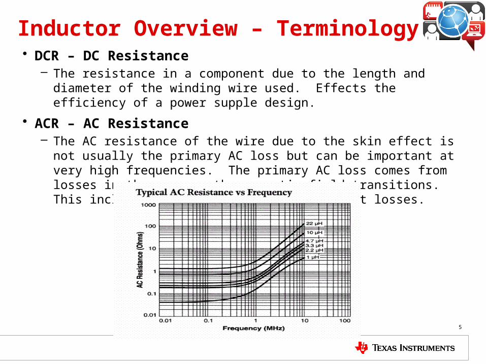
Inductor Overview – Terminology• DCR – DC Resistance
– The resistance in a component due to the length and diameter of the winding wire used. Effects the efficiency of a power supple design.
• ACR – AC Resistance– The AC resistance of the wire due to the skin effect is not usually the
primary AC loss but can be important at very high frequencies. The primary AC loss comes from losses in the core as the magnetic field transitions. This includes hysteresis and eddie current losses.
5

Inductor Overview – Terminology
• SRF – Self Resonant Frequency – The frequency at which the inductance of an inductor winding resonates
naturally with the distributed capacitance characteristic of that winding.
• Isat – Saturation Current – The amount of current flowing through an inductor that causes the
inductance to drop due to core saturation.
6

Inductor Overview – Terminology
• Irms – RMS Current – The amount of continuous current flowing through an inductor that causes
the maximum allowable temperature to rise
7
8
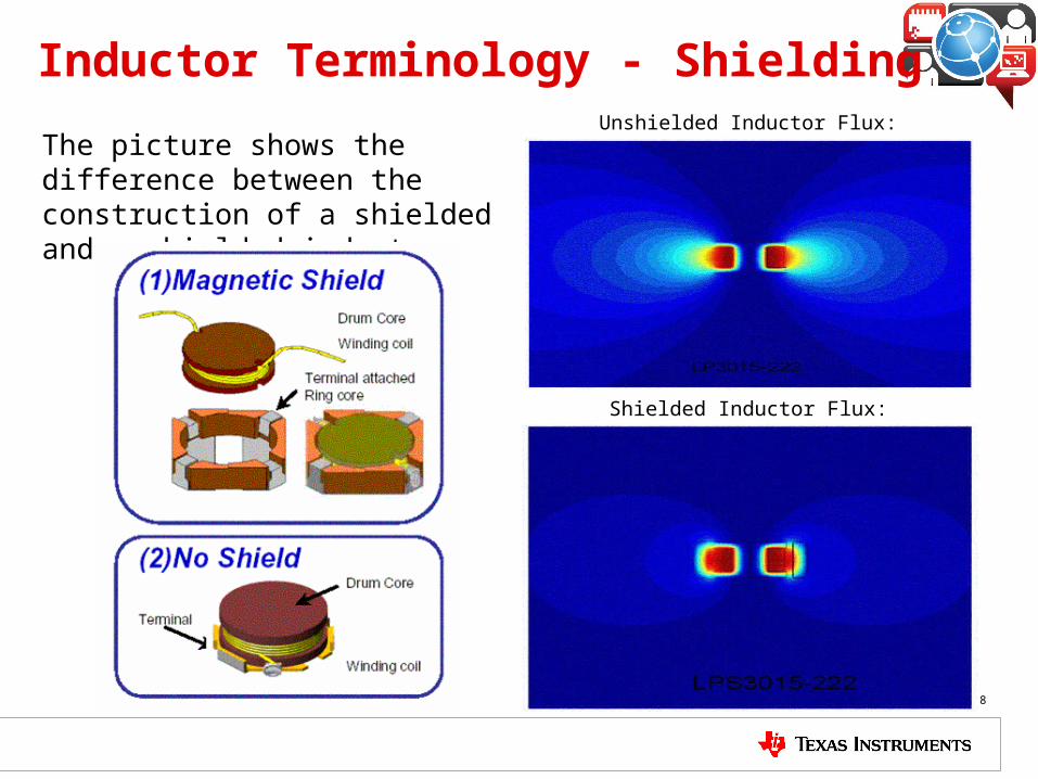
Inductor Terminology - Shielding
The picture shows the difference between the construction of a shielded and unshielded inductor
Unshielded Inductor Flux:
Shielded Inductor Flux:

9
Inductor Terminology – Core Material
1) Ferrite cores
a) Come in a variety of shapes
b) Operate at high switching frequencies
c) Have fairly steep saturation of inductance.
2) Iron Powder cores
a) Molded into a standard slug shape
b) Higher core losses make it unsuitable for high switching frequencies
c) Shallow saturation of inductance makes it very useful for high current low ripple designs.
Typical Saturation Curve for Iron Powder
Typical Saturation Curve for Ferrite

10
Thank you!


