25
Switching Realization
| Date post: | 14-Dec-2015 |
| Category: |
Documents |
| Upload: | ferdad4real |
| View: | 258 times |
| Download: | 0 times |

Switching Realization

Switch and Circuit Realization
• Switches– Transistor, BJT, MOSFET, IGBT, Diodes,
Thyristors
• How are switches arranged?– To realize circuit requirements and to satisfy
KVL and KCL of circuits– For quadrant operations
Realization of Switch
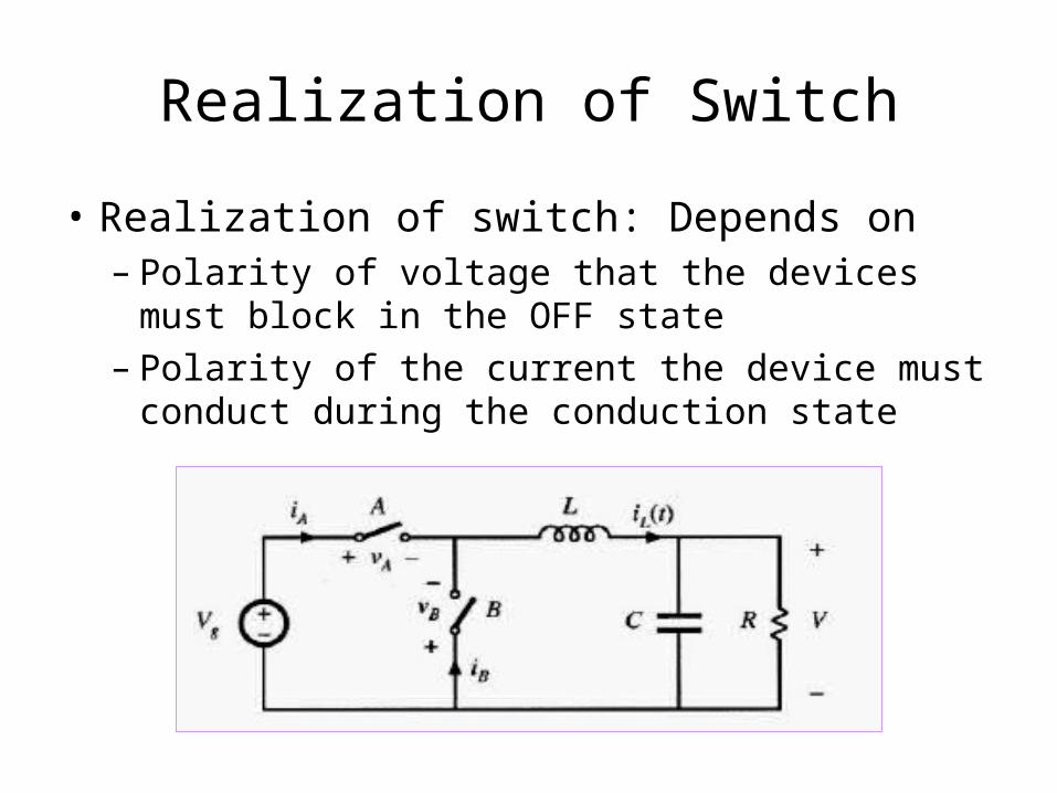
• Realization of switch: Depends on– Polarity of voltage that the devices must block
in the OFF state– Polarity of the current the device must
conduct during the conduction state

Realization of Switch contd..
• Refer the figure above– Switch A must block positive voltage Vg when
in OFF state
– Must conduct positive current IL in positive direction in the ON-state
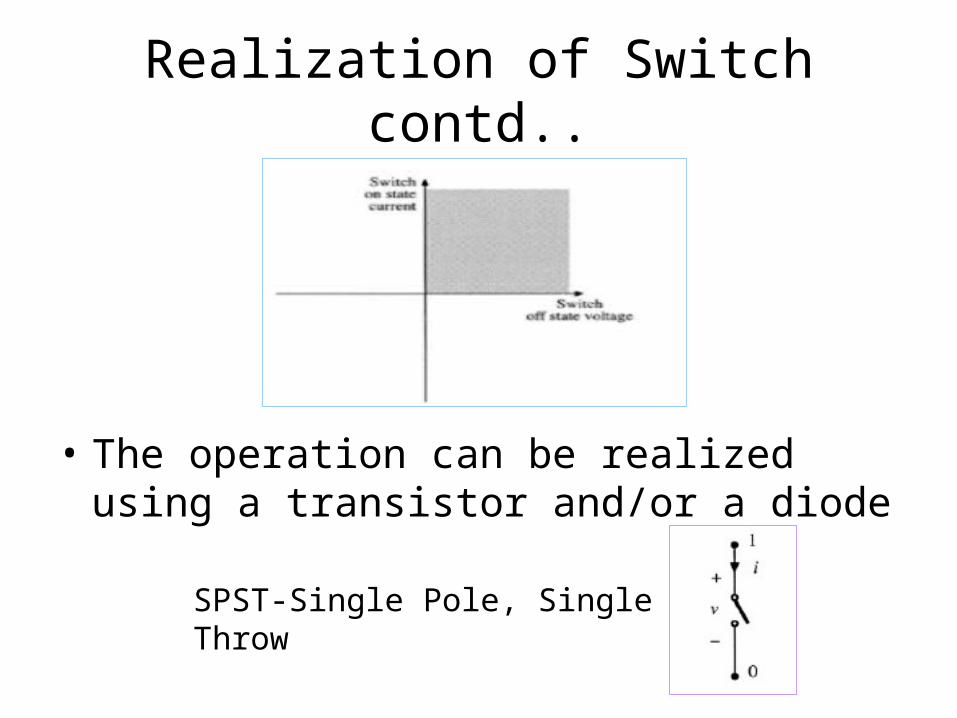
• If for all operating conditions the current and blocking voltage lie in a single quadrant
Realization of Switch contd..
• The operation can be realized using a transistor and/or a diode
SPST-Single Pole, Single Throw

Passive Switches
• Single-Quadrant Switches SPST Passive and Active Switches– Passive switches have terminals 1 and 0
while active switches have additional terminal C for control action
– Passive switches operate in ON and OFF positions depending on the voltage and current waveforms [V,I]

Passive Switches : Diode
• Passive Switch- Diode
• Ideal Diode: Requires V(t), I(t) waveforms to turn ON/OFF – Diode OFF, when– Diode ON, when
0)( tV0I0I 0)( tV

Active Switches: BJT
• Active Switch- With Control C– Thyristor, BJT, MOSFET, IGBT
• BJT: Bipolar Junction Transistor

• MOSFET: Metal Oxide Semiconductor Field Effect Transistor
Active Switches: MOSFET
Active switches contd..
• When control terminal C causes device to be OFF and the device is capable of blocking positive voltage
• When control terminal C causes device to be in ON-state V = 0 and is capable of conducting positive current
• The reverse block characteristics of BJT and IGBT are poor or non-existent
0V
0I
0I

Active switches contd..
• MOSFET is able to conduct current in reverse direction but is rarely used– Example:

Active Switches contd..
• Switch A can be IGBT, BJT or MOSFET
• Switch B can be Diode i.e. OFF when
0BV

Current Bidirectional 2-Quadrant Switches
• DC-AC Inverters require switches to conduct both negative and positive currents but block only positive voltages
• A current Bidirectional two Quadrant SPST switch can be realized using a transistor and an anti-parallel diode

Current Bidirectional 2 Quadrant Switches contd..
• A SPDT-single pole double throw current bidirectional two quadrant switch can be derived using two SPST switches

• Two quadrant SPDT switch
• A current Bidirectional SPDT switch– Conducts both positive and negative currents– Blocks positive voltage
Current Bidirectional 2 Quadrant Switches contd..

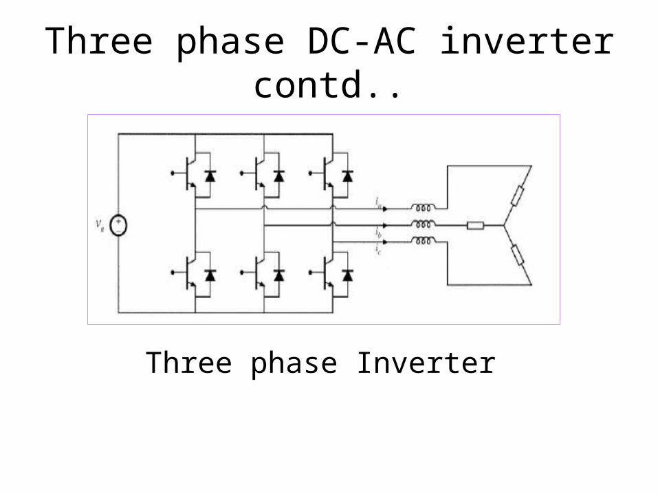
Three phase DC-AC Inverter• Has 3 two quadrant SPDT switches one
per phase• Each switch block input voltage Vg,
conduct output currents
Three phase DC-AC inverter contd..
Three phase Inverter

Battery Charger• Battery charger
• Vbus > 0, Vbatt > 0
• Q1, Q2, D1, D2 block positive voltage Vbatt

Battery Charger contd..
• Charging mode:– IL > 0, Q1 and D2 alternately conduct current
• Discharging mode:– IL < 0, Q2, D1 alternately conduct current
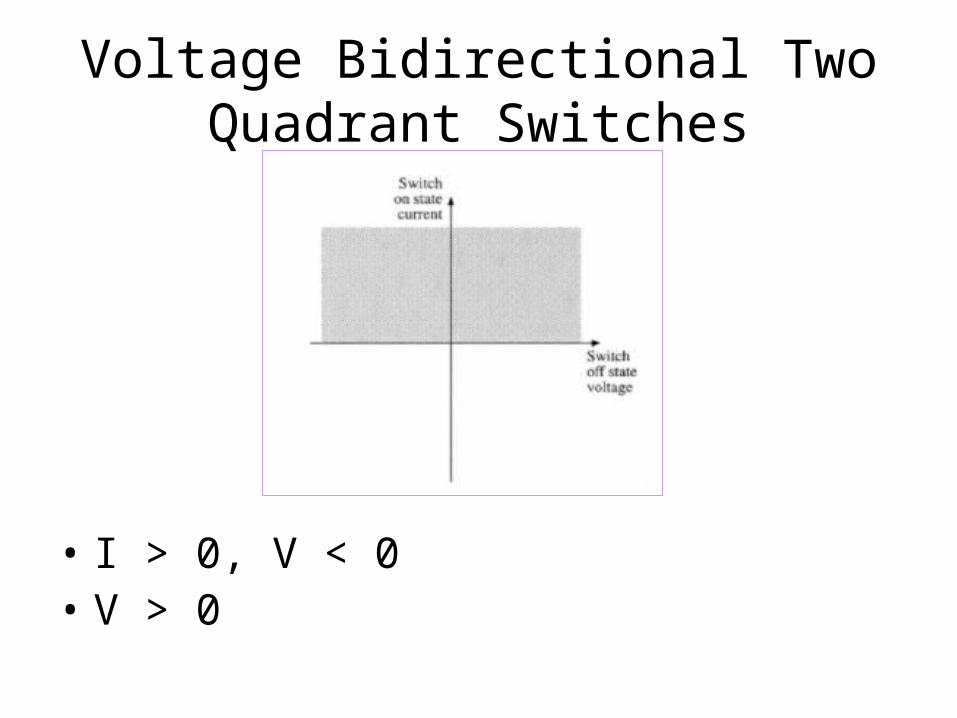
Voltage Bidirectional Two Quadrant Switches
• I > 0, V < 0• V > 0
Voltage Bidirectional two quadrant switches contd..
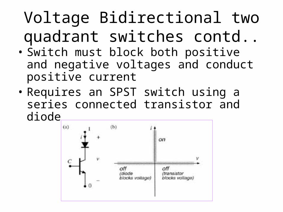
• Switch must block both positive and negative voltages and conduct positive current
• Requires an SPST switch using a series connected transistor and diode

Voltage Bidirectional 2- Quadrant Switches contd..
• In OFF state, controller turns OFF the transistor. Diode blocks negative voltage and transistor blocks positive voltage
• Blocks negative voltage up to diode voltage rating
• Blocks positive voltage up to transistor voltage rating
• Example: DC-AC Buck-Boost Inverter

DC-AC Buck Boost Inverter
• Inverter mode IL > 0
• All switches conduct only positive current
• Switches must block output AC line-line voltage
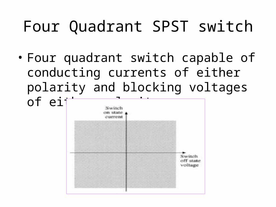
Four Quadrant SPST switch
• Four quadrant switch capable of conducting currents of either polarity and blocking voltages of either polarity

Four Quadrant SPST switch contd..
Three ways of implementing a four-quadrant SPST switch


