Dial Facilities Management Practices SWITCHING SYSTEMS MANAGEMENT NO. 4 ELECTRONIC SWITCHING SYSTEM SYSTEM DESCRIPTION CONTENTS PAGE CONTENTS (Cont) 1. GENERAL 1 E. Master Control Console I 2. APPLICATIONS AND FEATURES 1 6. SIGNAL CONTROL DEVICES A. Signaling 2 A. Signal Processor B. CAMA 2 B. Common Channel Interoffice Signaling c. Major Equipment Components 3 3. TRUNK ARRANGEMENTS 3 7. SERVICE AND MISCELLANEOUS CIRCUITS A. Unitized Metallic Trunk Frame 3 A. Multifrequency Units B. Unitized Terminal Equipment 3 B. Code 100-Type Test Codes c. Voiceband Interface Frame 4 c. Recorded Announcements D. Digroup Terminal. 4 D. Ringing and Tone Circuits 4. NETWORK 4 E. Miscellaneous Circuits A. Time Slot Interchange 4 8. WORK CENTERS B. Time Multiplexed Switch 5 A. Maintenance Operations Center c. Network Clock 5 B. Network Management Center 5. 1A PROCESSOR 6 c. Machine Administration Center A. Central Control 6 D. Trunk Operations Center B. Core Memory . 6 E. Terminal Equipment Center c. File Store System 7 D. Auxiliary Data System 8 Printed in U.S.A. Division H Section 9a March 1974 PAGE 8 8 9 9 10 10 10 10 11 11 11 12 12 12 12 12 Contents Page 1 of 2
Transcript
Dial Facilities Management Practices
SWITCHING SYSTEMS MANAGEMENT
NO. 4 ELECTRONIC SWITCHING SYSTEM
SYSTEM DESCRIPTION
CONTENTS PAGE CONTENTS (Cont)
1. GENERAL 1 E. Master Control Console I
2. APPLICATIONS AND FEATURES 1 6. SIGNAL CONTROL DEVICES
A. Signaling 2 A. Signal Processor
B. CAMA 2 B. Common Channel Interoffice Signaling
c. Major Equipment Components 3
3. TRUNK ARRANGEMENTS 3 7. SERVICE AND MISCELLANEOUS
CIRCUITS
A. Unitized Metallic Trunk Frame 3 A. Multifrequency Units
B. Unitized Terminal Equipment 3 B. Code 100-Type Test Codes
c. Voiceband Interface Frame 4 c. Recorded Announcements
D. Digroup Terminal. 4 D. Ringing and Tone Circuits
4. NETWORK 4 E. Miscellaneous Circuits
A. Time Slot Interchange 4 8. WORK CENTERS
B. Time Multiplexed Switch 5
A. Maintenance Operations Center c. Network Clock 5
B. Network Management Center 5. 1A PROCESSOR 6
c. Machine Administration Center A. Central Control 6
D. Trunk Operations Center B. Core Memory . 6
E. Terminal Equipment Center
c. File Store System 7
D. Auxiliary Data System 8
Printed in U.S.A.
Division H Section 9a
March 1974
PAGE
8
8
9
9
10
10
10
10
11
11
11
12
12
12
12
12
Contents Page 1 of 2
Div. H, Sec. 9a March 1974
CONTENTS (Cont)
9. CALL PROCESSING
A. Example 1 .
B. Example 2.
c. Example3.
D. Example4.
E. Local Tandem Operation
FIGURES
1. Analog and Digital Transmission
2. No. 4 ESS Block Diagram
3. Voiceband Interface Frame •
4. Voiceband Interface Unit Functions
5. Network Relationships
6. Time Slot Interchange Frame
7. Time Multiplexed Switch
8. Network Clock . . . .
9. Program Store-Call Store FrameFront View ..•.....
10. Program Store-Call Store Frame-Rear View
Contents Page2of 2
PAGE
13
13
14
15
15
15
17
18
19
20
21
22
23
24
25
25
Dial Facilities Management Practices
CONTENTS {Conti
11. Organization of Data on Disk . .
12. Basic Block Diagram of File Stores
13. File Store Controller Frame .
14. File Store Frame
15. Auxiliary Data System Block Diagram
16. Tape Unit Frame • • . • •
17. File Store Frame With Data Unit Selector . • • • • . . •
21. Analog Carrier Systems Utilizing Single Frequency Units . . • . . . .
22. Analog Carrier Systems Utilizing Common Channel Interoffice Signaling . . • .
23. Digital Carrier Systems, Application During Phase I, Utilizing Common Channel Interoffice Signaling . . . . • . . .
24. Combination Showing Digital Phase II • • . . . • •
34
35
36
37
Dial Facilities Management Practices Division H Section 9a
March 1974
SWITCHING SYSTEMS MANAGEMENT
NO. 4 ELECTRONIC SWITCHING SYSTEM
SYSTEM DESCRIPTION
1. GENERAL
1.01 This section consists of a general description of the No. 4 Electronic Switching System
(No.4 ESS) including its applications and capacities. The description of each type of component includes its function, physical appearance, and its relationship to the system and to call processing.
1.02 References in these sections to methods, planning, data requirements, service levels,
and equipment quantities are based on American Telephone and Telegraph Company recommendations.
1.03 Each time a figure is referenced in a paragraph throughout Section 9a. the
paragraph number will appear in parentheses beside the title of the figure. This procedure will be helpful to the reader as a reference between figure and text.
2. APPLICATION AND FEATURES
2.01 No. 4 ESS is a 4-wire electronic switching system developed for toll and tandem
applications. The estimated capacity is as follows:
(a) Busy-hour attempts (10 high day)-350,000
(b) Busy-hour attempts (peak)-385,000
( ~) Busy-hour CCS capacity (10 high day)-1,000,000
(d) Busy-hour CCS capacity (peak)-1,700,000
(e) Maximum terminations-107,500
(f) Maximum peak-day busy-hour first trial percent blocking-.5 percent
These capacities represent approximately three times the attempt handling capacity and five times the terminal capacity of a No. 4A Crossbar System. As a practical matter, the limitations of a switching system are determined by the type and mix of traffic at that specific office.
2.02 No. 4 ESS is an electronic switching system controlled by a simple stored program central
control (lA processor) operating in a "one task at a time" time division mode. It controls a time division switching network through which all connections are made on a digital pulse code modulation basis. A high proportion of the inputs to and outputs from the lA processor are made via a signal processor which has direct connections. to each trunk and service circuit.
2.03 No. 4 ESS provides most of the features available in No. 4A Crossbar Systems equipped
with Electronic Translator Systems (ETSs) plus a significant number of improvements. Among the general features included in the No. 4 ESS are 4-wire switching, time-division network, increased capacity, improved speed of service, reduced floor space, and full growth capabilities to maximum capacity. Some of the operational features include MF, DP, and common channel interoffice signaling (CCIS); office data and parameters changeable via local input/output devices (cathode ray tube or teletypewriter); full traffic, plant, and network management measurements; improved network management capabilities; decreased administrative work; and modernized maintenance features. Speed of service is an important consideration of the No.
This material is prepared for Bell System purposes and is for the use of Bell System
employees only. Its distribution is in no sense a publication. Neither the material nor
any portion thereof is to be reproduced in any form by others without the written
permission of the American Telephone and Telegraph Company.
Printed in U.S.A. Page 1
Div. H, Sec. 9a March 1974
4 ESS design. Both end-to-end call setup and charging accuracy have been improved. The No. 4 ESS can handle CAMA calls (both ANI and ONI) and calls to and from 3CL-type switchboards or their electrical equivalent. It is also capable of operation with the Traffic Service Position System (TSPS).
2.04 Included in the features to be made available later are the capabilities for (1) switching
PICTUREPHONE® and wideband data traffic, (2) serving as an international gateway office and (3) handling tandem traffic for a common control switching arrangement (CCSA).
2.05 Aside from the improvements in solid-state devices and increased attention to digital
transmission systems (eg, Tl and T2), one of the major differences between No. 4 ESS and previous toll switching systems is the use of pulse code modulation in a time division switching network. This digital switching arrangement offers significant technical and economic advantages over other systems.
2.06 For many years, analog transmission facilities have been used extensively (Fig. lA); voice
transmission ·is modulated and amplified. Each stage of amplification introduces some degree of noise. Switching introduces more noise. With the advent of digital transmission systems (Fig. lB),
Dial Facilities Management Practices
voice signals are coded into signals which can be regenerated rather than amplified. For this reason, noise and loss are not cumulative. In addition, digital systems offer some maintenance and cost advantages. To further utilize the advantages of digital transmission (Fig. lC), the No.4 ESS machine includes the capability to switeh digital signals without a conversion to analog.
2.07 The No. 4 ESS utilizes various trunk arrangements as inputs to the solid-state
time division digital network. The main control unit is the lA processor but in addition, signal processors consisting of wired-logic control units are used to accomplish the repetitive and time consuming functions such as service requests, answer detection, digit collection, and digit transmission. Service and miscellaneous circuits are provided for call processing and maintenance activity. Also, several administrative functions are performed in various work centers established as part of the switching entity.
A. Signaling
2.08 Three types of signaling are provided by the No. 4 ESS: multifrequency (MF) pulsing,
dial pulsing (DP), and common channel interoffice signaling (CCIS). The following tabulation represents the characteristics of the MF and D P signaling for No.4 ESS.
DIGITS MAX DIGITS PULSE
PULSING TO• FROM• RATE/SEC DELETES PREFIXES
MF 14 14 7D or 10D Oto 14 Oto6
DP 14 14 10PPS
* Distant office
The Common Channel Interoffice Signaling (CCIS) System may be used to pass address, supervisory, and control information when the distant office is equipped for CCIS. All features planned for the domestic implementation of CCIS are incorporated in the initial No. 4 ESS design (refer to 6.07).
Page2
Oto 14 Oto6
B. CAMA
2.09 A Centralized Automatic Message Accounting (CAMA) System is provided as a feature
that can be used when the originating office is not capable of collecting the charging information (ie,
Dial Facilities Management Practices
not equipped with AMA). The following are some CAMA characteristics (maximum):
(a) CAMA trunks (local to 4 ESS)-4500
(b) CAMA position trunks-72
(c) Numbering plan areas (NPAs) served-8.
No. 4 ESS is compatible with switching systems that have automatic number identification (AND equipment. In the event of ANI failure or inconsistent calling party charge data, the No. 4 ESS uses operator number identification (ONI) to identify the calling party. CAMA traffic sampling is provided to record data on all CAMA calls (ie, completed and uncompleted) on a 1-out-of-N basis where N can be varied from 1 to 99. Controlled recording of data for information type calls (eg, 1 + 411) is available; this is used to detect fraud. Special billing numbers (eg, credit card) billing may be recorded.
C. Major Equipment Components
2.10 The No. 4 ESS can be considered as six basic groups of equipment components as
follows (Fig. 2):
(a) Trunk arrangements
(b) Network
(c) 1A processor
(d) Signal control devices
(e) Service and miscellaneous circuits
(f) Work centers.
Individual components of the six equipment groups will be described under the preceding headings.
3. TRUNK ARRANGEMENTS
3.01 A No. 4 ESS has the capability of receiving analog signals and/ or digital signals for
switching operations. Equipment is provided to convert the received signal into standard inputs for the No. 4 ESS. This equipment consists of:
(a) Unitized metallic trunk frame (UMTF)
Div. H, Sec. 9a March 1974
(b) Unitized terminal equipment (UTE)
(c) Voiceband interface frame (VIF)
(d) Digroup terminal (DT).
A-. Unitized Metallic Trunk Frame
3.02 Analog trunks terminating at a No. 4 ESS office via noncarrier facilities require terminating
sets, balancing networks, amplifiers, and signal converters. These trunks are wired into metallic trunk circuits which are provided in the form of plug-in units mounted on a unitized metallic trunk frame. One 2-foot 2-inch wide bay contains sufficient devices plus maintenance access for 72 trunks. One plug-in trunk unit is required for each noncarrier trunk to be terminated.
B. Unitized Terminal Equipment
3.03 Trunks arriving via carrier facilities require modulation and demodulation equipment,
signaling units, echo suppressors, pads, and maintenance access in various configurations. Each frame is described in the following paragraphs.
Analog Carrier Unitized Terminal Equipment
3.04 Four voice frequency frames were developed for use with analog carrier systems.
(a) Unitized A6-FWA Frame: A6 channel banks, FW A signaling units, pads, and
maintenance access for 96 circuits on a 2-bay 4-foot 4-inch wide frame.
suppressors (ESs), pads, and maintenance access for 72 circuits on two 2-bay 4-foot 4-inch wide frames.
(c) Unitized A6-ATT Frame: For use with common channel interoffice signaling (CCIS)
trunks. Contains A6 channel banks, "P" attenuators (ATTs), and maintenance access for 96 circuits on a 2-foot 2-inch bay.
(d) Unitized A6-ATI'-ES Frame: For use with CCIS trunks. Contains A6 channel banks,
4A echo suppressors (ESS), "P" attenuators (ATTs), and maintenance access for 48 circuits on a 2-bay 4-foot 4-inch wide frame.
Page 3
Div. H. Sec. 9a March 1974
Digital Carrier Unitized Terminal Equipment
3.05 Before the digroup terminal becomes available (and under certain circumstances afterward),
digital carrier unitized terminal equipment will be installed in No. 4 ESS offices for direct termination of digital carrier. The persons directly responsible for determining the type of UTEs to be used (ie, Transmission or Equipment Engineers) should be consulted by the Traffic Engineer to ascertain what plan is to be followed.
3.06 When digital carrier trunks are terminated directly on D-type channel banks, each digital
signal is converted to an analog signal with the proper transmission levels. The resulting analog outputs are then connected to a voiceband interface unit (VIU) and receive the same treatment as any other analog trunk, ie, input to the VIU and converted into digital form for switching.
C. Voiceband Interface Frame
3.07 The equipment located in the metallic trunk frames (3.02) and the unitized terminal
equipment frames (3.04) have either single frequency units or trunk circuits which detect supervisory and dial pulse signals and pass this information to the central control via the signal processor. The 4-wire voice path is terminated on a voiceband interface frame (VIF). This frame converts the analog input into a pulse code modulated digital signal for switching. The VIF (Fig. 3) is a 7-foot 3-bay structure housing 7 working voiceband interface units (VIUs), one spare VIU, one control unit, and associated power supplies. The standby VIU is identical to the seven working VIUs and is used as an automatic replacement if any of the working VIUs should fall.
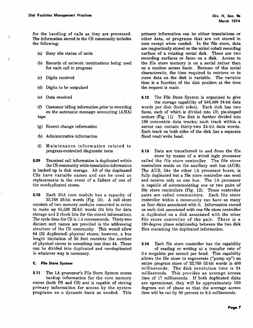
3.08 Each VIU has 128 channels but only 120 are used for trunks and service circuits. Only
120 input terminal sets are provided. Each of the 128 analog inputs to the VIU (Fig. 4) is sampled at an 8 kilohertz rate (8000 times per second) to produce a pulse amplitude modulated (PAM) signal. Each sample is encoded into an 8-bit code (Fig. 4). Each of the 128 samples occupies a 976-nanosecond time slot channel; the entire sequence of 128 samples is repeated each 125 microseconds (one time frame). A single coaxial cable carrying this bit stream is the output of each VIU (7 coax/VIF).
Page 4
Dial Facilities Management Practices
D. Digroup Terminal
3.09 A digroup terminal (DT) now in development will combine the functions of D-type digital
channel banks and VIUs. The DT unit will serve 5 digital groups (digroups of 24 channels each) or 120 trunks. The DT separates voice from signaling and presents each trunk, on a digital basis, to the switching network bypassing the VIF. This process eliminates the double conversion from digital to analog to digital for switching through the network.
3.10 A second type of signal processor, signal processor II (SP II), is being developed in
conjunction with the DT. As planned, the DT and SP II frames will form a lineup capable of processing and connecting 160 digroups or 3840 trunks.
4. NETWORK
4.01 Voiceband traffic in No. 4 ESS is switched over a solid-state, time-shared, digital
network. This network can terminate 107,520 trunks and service circuits. Computer simulations indicate that this network can carry 1,700,000 CCS during the peak day busy hour with a first trial matching loss of 0.5 percent. Switching occurs in the time slot interchange and in the time multiplexed switch. Each network unit will be discussed separately. The sequence is listed below.
(a) Time slot interchange
(b) Time multiplexed switch
(c) Network clock.
An overall block diagram (Fig. 5) shows the interrelationship of the voiceband interface units, the time slot interchange, and the time multiplexed switch.
A. Time Slot Interchange
4.02 The time slot interchange (TSI) frame (Fig. 6) is a 6-foot 2-bay structure; each bay is 3
feet 3 inches wide. A frame contains two switching and permuting units plus duplication, power converters, and bus interface hardware. The new term, permuting, means to rearrange the order of the individual time slots into a different configuration. This process occurs in two parts referred to later in this section as deloading and decorrelating. Each switching and permuting unit
(
Dial Facilities Management Practices
accepts coaxial leads from one voiceband interface frame and performs four basic functions.
(a) Time buffering
(b) Switching
(c) Deloading
(d) Decorrelating.
4.03 For the first function, the pulse code modulation (PCM) data (Fig. 4) from the
VIUs are read into an incoming TSI buffer store in the TSI frame. These data are later read out of the buffer at a time selected by the path hunt program. This allows an input in one time slot to be switched (second function) into another time slot later in that time frame or in the next time frame. For example, the data arriving in time slot 46 of frame 1 can be output in time slot 31, frame 2.
Note: One pulse code modulated signal is 61 nanoseconds; 1 PCM frame consists of 10 signals; this uses 610 nanoseconds (10 X 61) of the 976-nanosecond time slot. The remaining 366 nanoseconds provide time for gating, setting up paths, and a margin to allow for logic delay.
The first and last stages of the four stages of switching occur in the time slot interchange frame (stages 0 and 3).
4.04 The third function, deloading, is necessary to expand the number of paths leading to
the TMS in order that any given path may be more lightly loaded and to make it likely that little blocking will occur. The characteristics of the network are such that at 0.9 Erlang (32.4 CCS) per trunk, only the traffic carried by 105 trunks (of the 120 connected) can be switched on each of the 1024. ports of the time multiplexed switch (TMS) while maintaining the blocking requirements. The TSI provides a 7 to 8 expansion such that traffic arriving via 7 coaxials (7 x 120 trunks = 840 trunks) is evenly distributed over 8 coaxials (8 x 10⁵ trunk load = 840 trunk load) toward the TMS.
4.05 The fourth function, decorrelating, is necessary to protect the network against highly
correlated traffic arriving on many trunks in the
Div. H, Sec. 9a March 1974
same trunk group. Decorrelation enables trunks to be sequentially distributed across the network reducing the requirement for load balancing while maintaining low blocking under most traffic conditions. The TSI performs a decorrelating function by distributing, via fixed wired logic gating paths, the trunks terminating on an input coaxial into 8 separate buffer memories (within the TSI) each of which has access to a separate port on the TMS.
B. Time Multiplexed Switch
4.06 The time multiplexed switch (TMS) is the central switching portion of the 4-stage
switching network. As previously mentioned, the first and last stages of switching are located in time slot interchange frames. The two center stages (stage 1 and stage 2) in the TMS are each made up of sixteen 16 by 16 switches to form a 256 by 256 grid. When fully equipped, an office will consist of eight TMS 2-bay frames (Fig. 7). At any particular time, four frames are actively operational and the four duplicate frames do the same work as the first four, on a standby basis, but are not part of the operating system. The 4 active frames in total provide 512 separate 2-way paths between the TSI frames. The entire switch is reconfigured by the time slot memory every 976 nanoseconds.
4.07 The No. 4 ESS can be equipped initially with one, two, or four duplicated TMS frames (a
tobl.l of two, four, or eight frames). The frames can be partially equipped in increments of one-fourth frame. Growth is accomplished by adding circuitry to existing partially equipped frames or by adding new frames.
C. Network Clock
4.08 Precise timing for synchronizing the high speed bit streams is required; this is supplied
by the network clock. The network clock frame consists of two 3-foot 3-inch wide bays (Fig. 8) with two complete clock chains per bay. All clock chains are identical. The four oscillators are assembled into a master slave network with an established hierarchy. Logic in the network clock frame automatically determines, from phase and level error detection, the "health" of each oscillator. In general, the healthiest oscillator is selected to be the master.
Page 5
Oiv. H, Sec. 9a March 1974
4.09 Oscillators in the network clock frame supply a stable 16.384 megahertz pulse train. Its
stability is one part in 10 to the tenth power per week. Because of the stability and high reliability of this frame, additional output signals are being considered to time other functions requiring these properties.
5. 1A PROCESSOR
5.01 The No. 4 ESS uses the 1A processor as the main control unit. This control consists
of duplicated frames of equipment with a common maintenance center. The 1A processor consists of:
(a) Central control
(b) Program store
(c) Call store
(d) File store system
(e) Auxiliary data system
(f) Master control console.
A. Central Control
5.02 The 1A processor's central control (CC) used in No. 4 ESS is an integrated circuit processor
which is faster and more powerful than its predecessors. It is designed to be more flexible both in memory arrangements and peripheral interfaces as well as easier to install and maintain.
5.03 Two versions of the core memory stores (program store and call store) have been
developed. With the initial (smaller) version, central control reads program instructions from memory stores on store buses at a maximum rate of 52 bits each 1.4 microseconds. Communication with peripheral units is via a peripheral. unit bus with the CC executing one command every 2.8 microseconds (minimum). A significant feature of the 1A central control is its capability of executing certain nonmemory associated orders in one-half the cycle time (ie, 700 nanoseconds) of the memory associated orders. This gives a net execution time of between four and eight times faster than earlier versions of central control depending on the mix of half-cycle and full cycle orders. Equivalent figures for the later (larger) version of the core memory store are not now available.
Page 6
Dial Facilities Management Practices
5.04 The central control is mounted on one 3-foot 3-inch wide frame. For service protection,
two frames are required in each office. The attempt handling capacity of the No. 4 ESS will depend principally on the amount of real time of the central control which will be consumed by the particular mix of the traffic call types switched. This will in turn affect the quantity of trunks that can be terminated on a specific No. 4 ESS.
B. Core Memory
5.05 As mentioned above, two versions of the core memory store have been developed.
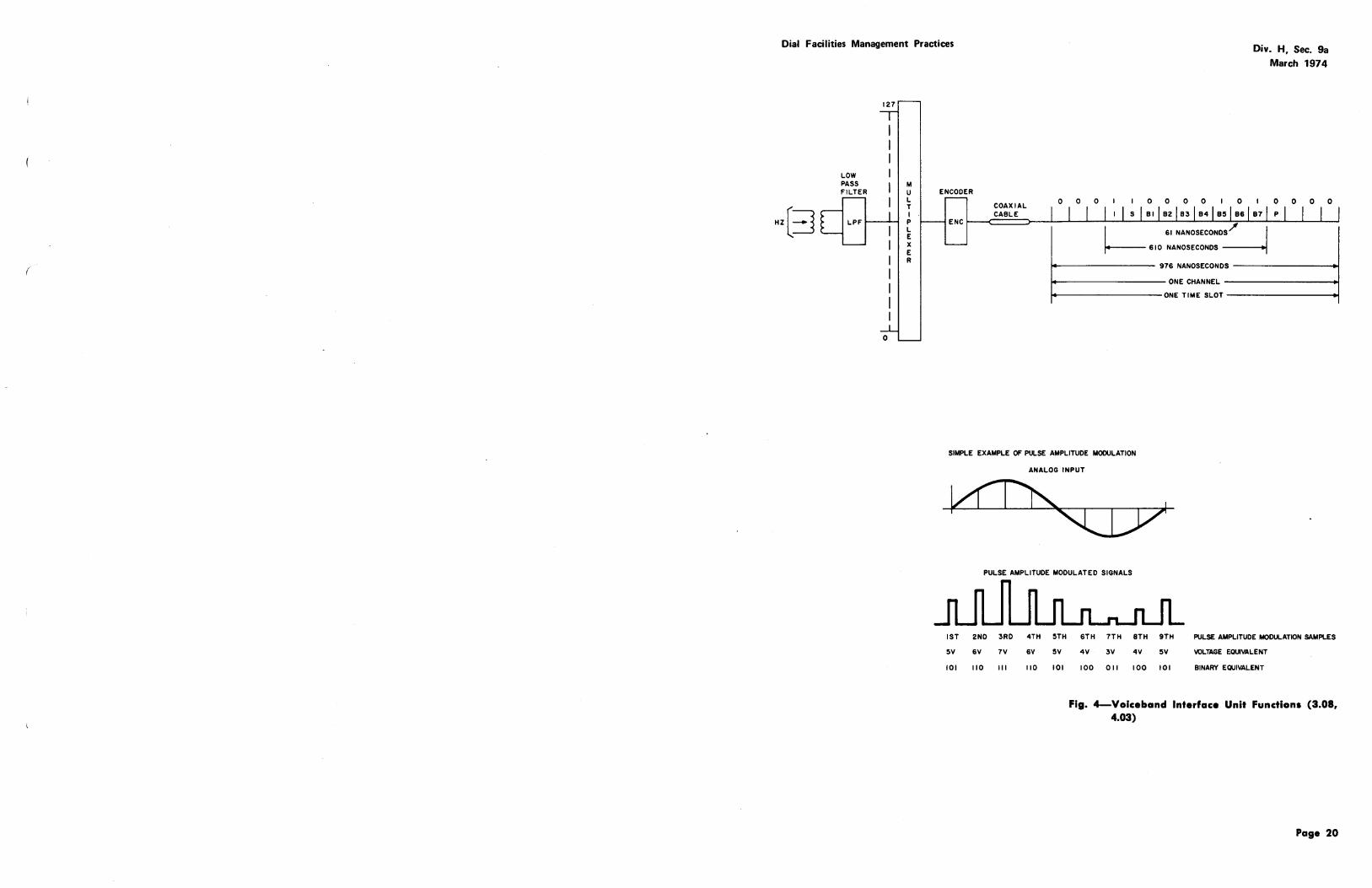
The information which follows pertains to the initial version, and similar information on the second version will be furnished as it becomes available. Both program store and call store utilize the same physical frame. These frames are single bays, 2 feet 2 inches wide and 7 feet high. Front and rear views showing the equipment locations are presented in Fig. 9 and 10. A single core store frame may be equipped with four 32,768-word (26 bits per word) modules.
Progrom Store
5.06 A program store (PS) uses a magnetic core random access memory to hold the operational
programs. The PS word size is 52 bits made up of either a 48-bit word or two 24-bit words with an additional four bits of check information. The physical store consists of two 32,768-word (26 bits per word) modules connected in parallel. Up to 31 PSs can be provided within the addressing structure of the 1A processor, but a 35-foot bus length limitation permits only about 16 to 20 stores in any office.
5.07 The PS community is not duplicated since the information stored therein is also contained
in disk storage. There are, however, two extra PS frames designated as "rovers". The two rover stores normally duplicate PS-0 and PS-1 (base stores). In the event a different PS fails, a rover store will be filled with the proper information from disk memory. This "pump-up" procedure will occur off line from normal call processing and will take about 400 milliseconds per program store.
Call Store
5.08 A call store (CS) is used as the temporary memory of the lA processor and is used
Dial Facilities Management Practices
for the handling of calls as they are processed. The information stored in the CS community includes the following:
(a) Busy idle status of units
(b) Records of network terminations being used for each call in progress
(c) Digits received
(d) Digits to be outpulsed
(e) Data received
(f) Customer billing information prior to recording on the automatic message accounting (AMA)
tape
(g) Recent change information
(h) Administrative information
(i) Maintenance information related to program-controlled diagnostic tests.
5.09 Transient call information is duplicated within the CS community while translation information
is backed up in disk storage. All of the duplicated CSs have variable names and can be used as replacements in the event of a failure of one of the nonduplicated stores.
5.10 Each 20A core module has a capacity of 32,768 26-bit words (Fig. 10). A call store
consists of two memory modules connected in series to make up 65,536 26-bit words (24 bits for data storage and 2 check bits for the stored information). The cycle time for CS is 1.4 microseconds. Thirty-two distinct unit names are provided in the addressing structure of the CS community. This would allow 64 (32 duplicated) physical stores; however, a bus length limitation of 35 feet restricts the number of physical stores to something less than 44. These can be divided into duplicated and nonduplicated in whatever way is necessary.
C. File Store System
5.11 The 1A processor's File Store System stores backup information for the core memory
stores (both PS and CS) and is capable of storing primary information for access by the system programs on a dynamic basis as needed. This
Div. H, Sec. 9a March 1974
primary information can be either translations or other data, or programs that are not stored in core except when needed. In the file store, data are magnetically stored on the nickel cobalt recording surface of a rotating metal disk. There are two recording surfaces or faces on a disk. Access to the file store memory is on a serial rather than on a random access basis. Because of this serial characterstic, the time required to retrieve or to store data on the disk is variable. The variable time is a function of the disk position at the time the request is made.
5.12 The File Store System is organized to give the storage capability of 646,400 24-bit data
words per disk (both sides). Each disk has two faces, each of which is divided into 101 pie-shaped sectors (Fig. 11). The disk is further divided into 100 concentric data tracks; each track within a sector can contain thirty-two 24-bit data words. Each track on both sides of the disk has a separate fixed read/write head.
5.13 Data are transferred to and from the file store by means of a wired logic processor
called the file store controller. The file store controllers reside on the auxiliary unit bus (AUB). The AUB, like the other 1A processor buses, is fully duplicated but a file store controller can send and receive only on one bus. The 1A processor is capable of accommodating one or two pairs of file store controllers (Fig. 12). These controller pairs are called communities. Each file store controller within a community can have as many as four disks associated with it. Information stored on each disk associated with one file store controller is duplicated on a disk associated with the other file store controller of the pair. There is a 180-degree phase relationship between the two disk files containing the duplicated information.
5.14 Each file store controller has the capability of reading or writing at a transfer rate of
2.4 megabits per second per head. This capability allows the file store to regenerate ("pump up") an entire program store of 32,768 52-bit words in 400 milliseconds. The disk revolution time is 34 milliseconds. This provides an average access time of 17 milliseconds. If both duplicated disks are operational, they will be approximately 180 degrees out of phase so that the average access time will be cut by 50 percent to 8.5 milliseconds.
Page 7
Div. H, Sec. 9a March 1974
5.15 The File Store System utilizes two types of frames. The file store controller frame
(Fig. 13) is a 7-foot by 2-foot 2-inch wide frame. The file store frame (Fig. 14) is a 7-foot by 3-foot 3-inch wide frame. Each file store frame contains one or two disks, one disk mounted above the other, and their respective drive motors. The file store controller frame contains the logic circuitry, power circuitry, air compressor, and bus drivers and receivers.
D. Auxiliary Data System
5.16 The Auxiliary Data System (ADS) of the 1A processor is a versatile, medium speed, data
handling system. This system, located on the auxiliary unit bus (AUB), consists of semiautonomous control units called data unit selectors (DUSs), data unit controllers (DUCs), and data units (DUs). Some of the functions performed by the ADS are system reinitialization and other program updating, system memory dumps for utility programs, recording of automatic message accounting data, traffic records, and plant measurements.
5.17 The ADS shown in Fig. 15 includes as many as 16 data units in any combination of data
sets or tape drives, each with its own data unit controller. The data unit selectors are provided as a pair with each data unit selector of the pair being associated with a particular auxiliary unit bus. Each data unit controller is connected to the data unit selector pair via duplicated internal buses called the data unit bus.
5.18 The data unit selector provides the control and interface functions necessary for the
transfer of data on a block basis between a character organized data unit and the word organized central control of the 1A processor.
5.19 The ADS allows the provisiOn of large amounts of relatively inexpensive memory
for situations where random access is not important. Since data transfer from a data unit is via a semiautonomous control unit, little real time is used. Data, such as traffic counts and translation changes, can be recorded in raw form on the magnetic tape unit. The data can then either be processed by the off-line controller or by the· on-line processor during low traffic periods.
5.20 Portions of the ADS are mounted in three different frames. The tape unit (TU) frame
Page 8
Dial Facilities Management Practices
is a 2-foot 2-inch wide frame shown in Fig. 16. The data unit selector circuitry is located in the uppermost portion of the file store frame as shown in Fig. 17. Details on the data link frame are as yet unavailable. These facts are to be incorporated as they are made available.
E. Master Control Console
5.21 The 1A processor's master control console (MCC) serves as a direct communication
link between the maintenance personnel and the system. The MCC indicates, by means of alarms and status indications, the current condition of the system. Controls are provided so that manual recovery of the system can be effected if the automatic recovery capability is not sufficient. One or more teletypewriters (TTYs) and cathode ray tube (CRT) terminals are provided to serve as the primary man/machine interface. When the system will not respond to TTY requests, control keys can be used to initiate recovery actions.
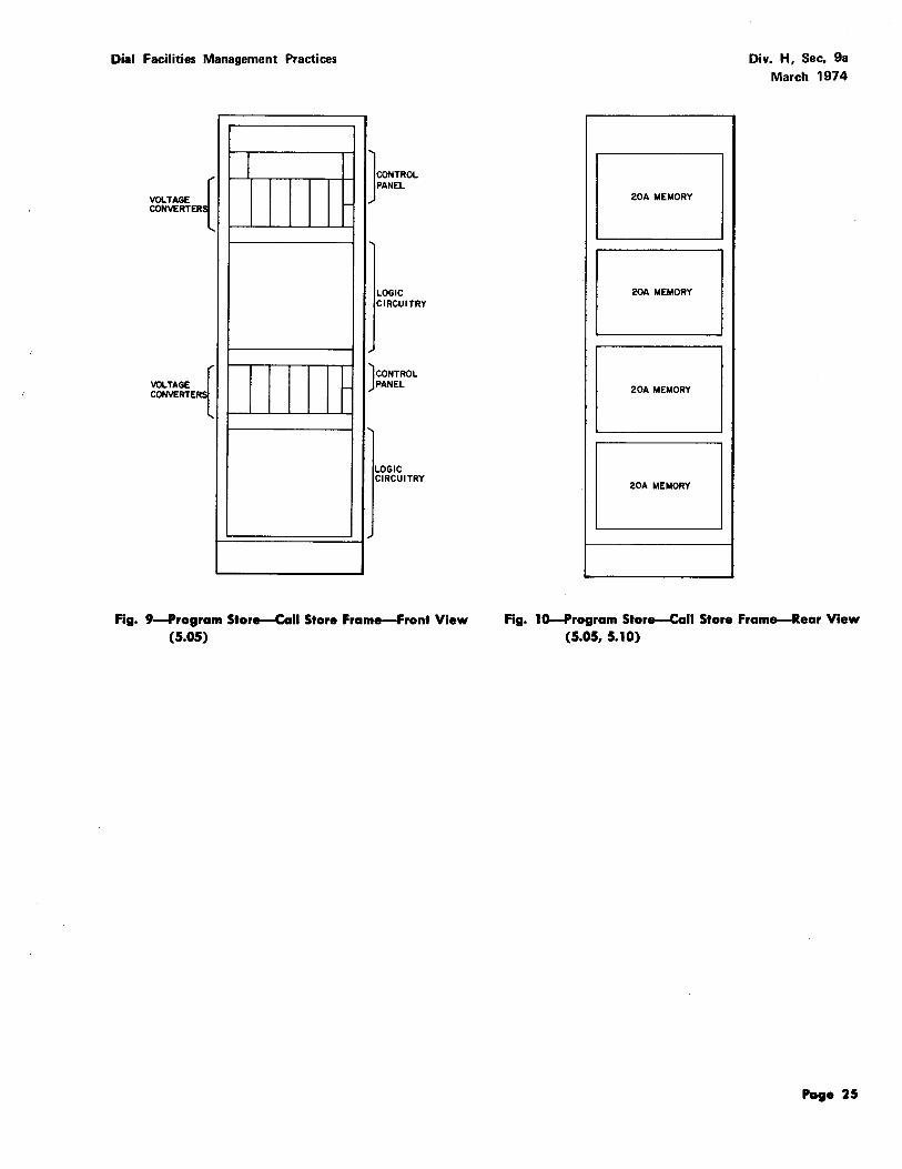
5.22 The MCC developed for use in No. 4 ESS is a sit-down type unit (Fig. 18) with the
control and display panel mounted on top. This console is flanked by the input/ output devices and the CALL DIRECTOR® telephone set. The MCC is not positioned with the 1A processor frames but is located in a maintenance operation center (MOC) a short distance away. However, all MCC controls and indicators are designed to allow control or monitoring from a remote location.
6. SIGNAL CONTROL DEVICES
6.01 The magnitude of trunks terminating at a No. 4 ESS office requires special procedures
for processing the signaling (on-hook, off-hook, digit reception, and digit transmission) associated with each call. To a large extent, the 1A processor concerns itself with the manipulation of a network used to connect the "voice" portion of a call and delegates the major portion of the signaling tasks to one of two units, a signal processor or common channel interoffice signaling terminal. The type of signal control device provided is dependent upon the planned signaling arrangement between the No. 4 ESS and the distant office involved on each trunk subgroup. Therefore, signaling operations can be processed by using either a signal processor, common channel interoffice signaling equipment, or a combination of the two. Furthermore, for those cases using a signal processor, there are
(
Dial Facilities Management Practices
two types available, ie, signal processor I and signal processor II. Signal processor I (SP I) is used for analog trunks or trunks that are converted to an analog basis and are terminated on a voiceband interface unit (VIU). Signal processor II (SP II) will be used only with the digroup terminal on which digital trunks may be terminated directly, ie, bypassing the VIU. Information on SP II will be issued when it becomes available. This section supplies information for SP I only; therefore, use of the term "signal processor (SP)" refers to SP I.
A. Signal Processor
6.02 Each trunk incoming to a No. 4 ESS office is connected to a unitized terminal equipment
frame, metallic trunk frame, or a digroup terminal. Equipment in these frames separates the voice and signaling paths for non-CCIS type trunks. In the case of unitized terminal equipment frames and metallic trunk frames, the talking paths are connected to VIUs and the signaling paths consist of E (receiving) and M (transmitting) leads to and from (respectively) the SP. For digroup terminals, the arrangement is as presently covered under 6.01, 3.09, and 3.10.
6.03 A SP provides scanning inputs from each trunk to receive signaling, supervisory and
miscellaneous incoming signals, and signal distributing outputs to each trunk for transmitting signaling and supervisory outputs. "Scans" are passed on to the central control and indications from the central control furnish the basis for signal distributor actions. In addition, the SP can utilize its scanner and signal distributor to advise the CC of "changes of state" in various items of equipment. Under the direction of the CC, the SP can operate various relay applique and pulse points.
6.04 Some examples of these scanning and signal distributing functions within the office are:
(1) scan a multifrequency (MF) receiver (service circuit) and report to CC the digits received via MF inpulsing, (2) utilize the signal distributor to outpulse dial pulse (DP) digits, and (3) report to CC any alarm conditions that might occur.
6.05 A SP consists of a control frame and two matrices which are identical in format. The
control equipment, which is duplicated within each SP, includes the memory and logic necessary for autonomous scanning, digit reception, signal
Div. H, Sec. 9a March 1974
distributing, and outpulsing functions. By using common circuitry for the scanning and signal distributing functions, cost savings can be realized. Each of the two matrices in a SP is divided into a universal section and a miscellaneous section. The universal sections contain a total of 4096 scan and 4096 signal distributor points, each category being arranged in 256 rows of 16 points each. The miscellaneous sections have up to 2048 scan and 2048 signal distributor points, each category being arranged in 128 rows of 16 points each. These scan and signal distributor points are assigned as required. For example, each MF trunk requires one universal scan and one universal signal distributor point. Each MF receiver (service circuit) requires seven miscellaneous scan points and two miscellaneous signal distributor points. The point requirements for trunks and various equipment components are fully covered in Traffic Facilities Practices.
6.06 The SP physically consists of eight bays combined into five frames. The five frames
are further grouped into an SP frame, a left matrix, and a right matrix (Fig. 19). The SP frame, consisting of two 2-foot 2-inch bays, contains duplicate sets of SP logic, peripheral unit bus interface circuits, and control panels for a fully equipped SP. Two 2-foot 2-inch bays are combined to make up a distribute and scan matrix frame. This frame is combined with a 3-foot 3-inch distribute applique frame to form a left or right matrix. It is important to note that assignments are not duplicated in the left and right matrices. In general, a total of 4080 message trunks can be terminated on a fully equipped SP. The coded enabling addressing scheme, by which the CC communicates to an SP, permits up to 32 SPs in a No. 4 ESS office.
B. Common Channel Interoffice Signaling
6.07 No. 4 ESS has the capability to provide common channel interoffice signaling (CCIS)
to handle the transmission of supervisory and address information for both domestic and international traffic. In CCIS, the voice and signaling portions of a call are separated at the originating office. The voice portion is transmitted in the usual manner over a conventional channel. The signaling portions of many such circuits are encoded by a data set and routed via a common signaling link between two offices. This separate common signaling link can be a standard voice bandwidth channel.
Page 9
Div. H, Sec. 9a March 1974
6.08 Each signal message carries a digital label to identify the particular circuit with which
it is associated. There is provision for sending multiunit messages consisting of several signal units under one label as well as individual messages. A supervisory telephone signal will normally be carried by a 1-unit message while a group of digits will be carried by a multiunit message.
6.09 There are three distinct equipment units that exist between the No. 4 ESS central
control and the CCIS channel. These are the data set, the signaling terminal, and the terminal access circuit (TAC).
7. SERVICE AND MISCELLANEOUS CIRCUITS
7.01 Service and miscellaneous circuits are common equipment items in the No. 4 ESS. With
few exceptions, these circuits are connected to the voiceband interface frame (each circuit having a separate appearance) and assigned in translations. Service and miscellaneous circuits are not permanently connected to any one trunk but instead are shared by all trunks having a need. They are connected to individual trunks when required via the No. 4 ESS switching network.
7.02 Circuits within this category consist of the following:
(a) Multifrequency units
(b) 100-Type test codes
(c) Recorded announcements
(d) Ringing and tone circuits
(e) Miscellaneous circuits.
A. Multifrequency Units
7.03 In No.4 ESS, the SP is used to autonomously control signa1ing operations. For supervision
(seizures, disconnects, winks, etc) and dial pulse digit collection, the SP directly scans the E lead of the associated trunk circuit. Multifrequency (MF) digits are collected by MF receivers and sent by MF transmitters. The SP utilizes its scanner to obtain the stored MF digits from the MF receiver and utilizes its signal distributor to operate tone points within the MF transmitter to send MF digits.
Page 10
Dial Facilities Management Practices
7.04 The No. 4 ESS offices have miscellaneous circuits called MF receiver test circuits and
MF transmitter test circuits. These units are used to test the MF receivers and MF transmitters.
B. Code 100-Type Test Codes
7.05 The code 100-type test codes are for use by maintenance personnel to test individual
trunk operations. The types of code 100-type test codes available and their purposes are as follows.
(b) Code 101-Talking connection between testboards
(c) Code 102-Transmits 1 kilohertz tone for level measurements
(d) Code 103-Tests signaling capability
(e) Code 105-"Responder'' for use with Automatic Transmission Measuring System (ATMS)
(f) Code 108-Echo suppressor operations tests.
Codes 100, 102, and 103 do not require any hardware in the No.4 ESS office; these functions are provided by the generic program. Quantities of code 100 test circuits are provided as a part of the 51A test positions. The code 105 and 108 hardware test units are ordered in quantities based on the number of trunks and trunk groups being installed.
C. Recorded Announcements
7.06 The recorded announcement facilities in No. 4 ESS differ from those presently used in
other switching systems in the Bell System. Each recorded announcement utilizes four recording heads. Each announcement interval is 16 seconds long with 12 seconds of speech and 4 seconds blank. Each announcement is placed on the recording drum. As the drum rotates, the recorded announcement is reproduced by the four heads. The net effect is 4 reproductions of the announcement with a 4-second displacement (in time) of each reproduction with respect to the next announcement phase. This in fact produces four phases of each announcement with only one recording. Connecting each trunk needing an announcement to the blank (or idle) interval, allows nonbarge-in (customer is
Dial Facilities Management Practices
always connected at the beginning of an announcement). An audible ring prior to the start of an announcement is not required (minimum delay to start = 0, maximum delay = 4 seconds, average delay = 2 seconds).
1.01 The method of distribution is also unique to the No. 4 ESS. The basic recorded
announcement (RA) frame provides the recording drum and equipment for nirle different announcements. The frame is duplicated for reliability. Thus, 72 network terminations are required (9 announcements X 4 phases X 2 duplications). The switching network then utilizes a dedicated time slot interchange (TSI) unit as a distribution bus (Fig. 20). The 72 network terminations (maximum 120) are routed to a single input port of a TSI. This input port is always switched to a specific output port which is connected to the dedicated TSI via a "nailed up" connection through the switching network (ie, assigned as a permanent connection). The dedicated TSis input and output ports are connected back to back as shown in Fig. 20. The net result is the ability to provide 760 outputs of any one recorded announcement. The network will of course share these outputs with all nine input recordings. The important feature is that the quantity of a single announcement will be supplied (up to the maximum) automatically as traffic conditions require.
D. Ringing and Tone Circuits
7.08 Ringing and tone circuits (busy, reorder, etc) are the standard types used in all
switching machines; however, the ringing and tone plant in the No. 4 ESS is a solid-state version. No. 4 ESS utilizes the dedicated TSI discussed under recorded announcement for distribution of each type of tone. The ringing and tone frame itself is not duplicated but the individual supplies are duplicated within the frame. In addition, there are duplicated network appearances for each tone for reliability.
E. Miscellaneous Circuits
7.09 There are several additional miscellaneous circuits associated with the No. 4 ESS such
as CCIS signaling link test circuits. These and other types that may be required and ordered are shown in Section 14-t.
Div. H, Sec. 9a March 1974
8. WORK CENTERS
8.01 The quantity and complexity of equipment within a No. 4 ESS office requires a planned
approach toward the principal work functions involved in operations, administration, and maintenance for the system. These principal work functions can be grouped broadly into the following categories:
(a) Equipment maintenance functions
(1) Switching equipment maintenance
(2) Terminal equipment maintenance
(b) Maintenance coordination and control functions
(1) Toll switching control
(2) Trunk maintenance control
(c) Network control
(1) Network management control
(2) Restoration control
(d) Office administration
(1) Machine administration
(2) Circuit provision.
8.02 The organization of work centers for No. 4 ESS offices may vary widely and will
depend upon (1) the size of the office, (2) existence of joint Long Lines - Associated Company operation (3) basic type of company operations organization (operations, switching department, traditional Plant - Traffic, etc) and (4) centralization of functions in one location (eg, network management). The following are illustrations of work centers which may be established at No. 4 ESS offices and their suggested names.
(a) Maintenance Operations Center
(b) Network Management Center
(c) Machine Administration Center
(d) Trunk Operations Center
(e) Terminal Equipment Center
Page 11
Div. H, Sec. 9a March 1974
A. Maintenance Operations Center
8.03 The maintenance operations center (MOC) functions to coordinate many maintenance
activities. Switching equipment maintenance is its primary equipment maintenance function. This work center will usually be placed adjacent to the switching processor. It will include the master control console, input/output devices to (1) receive system generated cathode ray tube (CRT) and teletypewriter (TTY) messages, (2) to input commands, (3) to monitor the data change channel from the machine administration center, and (4) to provide administrative data to maintenance personnel.
B. Network Management Center
8.04 The network management center (NMC) function is important to maintain service
continuity. It includes monitoring of network performance and implementation and removal of controls to maintain the best possible service under all conditions. Network management has a close operating relationship with the maintenance operations center, the trunk operations center, and the machine administration center. For this reason, it appears desirable for these centers to be closely located.
8.05 This area contains a network management exception panel (either desk or wall-mounted),
a cathode ray tube (CRT) terminal with keyboard, and one or more high-speed teletypewriters, desks (for supervision, clerical, and analysis-type work), and other office furniture as required.
C. Machine Administration Center
8.06 The machine administration center (MAC) has responsibility for office traffic performance.
This includes responsibility for trunk assignments, call routing administration, charging information in the translation data base, formulating translation data change messages, and control of office equipment assignment to optimize service and administrative records.
8.07 Ideally, maximum intracommunication should be provided so that any effects of recent
changes on system performance can be detected. The facilities at this center principally consist of
Page 12
Dial Facilities Management Practices
input/output devices (cathode ray tubes) for data change messages and TTY s for machine input and output.
D. Trunk Operations Center
8.08 The trunk operations center (TOC) is responsible for maintenance control of trunks.
This responsibility involves responding to indications of trunk faults, removing trunks from service, testing trunks, sectionalizing the fault to an equipment repair group, verifying corrected faults, and restoring trunks to service.
8.09 The facilities include the test positions (51A) from which trunks are tested and troubles
are sectionalized. Input/output devices are used in connection with the test positions to converse with the system for trunk maintenance.
E. Terminal Equipment Center
8.10 The terminal equipment center (TEC) has responsibility for the voiceband interface
units (VIUs), signal processors (SPs), digroup terminals (DTs), 51A test positions, service circuits, unitized terminal equipment, miscellaneous voice frequency signaling interface equipment, and various switched access maintenance circuits such as test lines.
8. 11 This work center will probably be an area that is centrally located with respect to the
terminal equipment. Operating companies may wish to establish more than one terminal equipment maintenance center if the maintenance force for this function is large and the equipment is spread over more than one floor of the building.
Dial Facilities Management Practices
9. CALL PROCESSING
9.01 Call processing in the No. 4 ESS is under stored program control and follows a stimulus
response philosophy. In general, call stimuli consist of externally generated reports via the signal processor such as seizure, digits, off-hook, on-hook, stop dial, etc, and internally generated reports such as timing and queuing. These stimuli are processed by task dispenser programs which transfer to appropriate task programs. The task programs respond by taking action which processes the present call state into the next call state. The procedure is continued until completion of the call on successful attempts or the appropriate disposition of ineffective attempts such as abandons, vacant code, no circuit conditions, etc. Any further discussion of the many programs involved in processing calls is considered beyond the scope of this section.
9.02 To illustrate the flow of some typical calls, four examples will be covered using different
transmission and signaling arrangements. In each example, the call originates in a No. i ESS and completes to a distant No. 1 ESS through a No. 4 ESS.
(a) Example 1: Analog carrier systems utilizing SF units (Fig. 21)
(b) Example 2: Analog carrier systems utilizing common channel interoffice signaling (Fig. 22)
Div. H, Sec. 9a March 1974
(c) l?r.ample 3: Digital carrier systems, application during phase 1, utilizing common channel
interoffice signaling (Fig. 23)
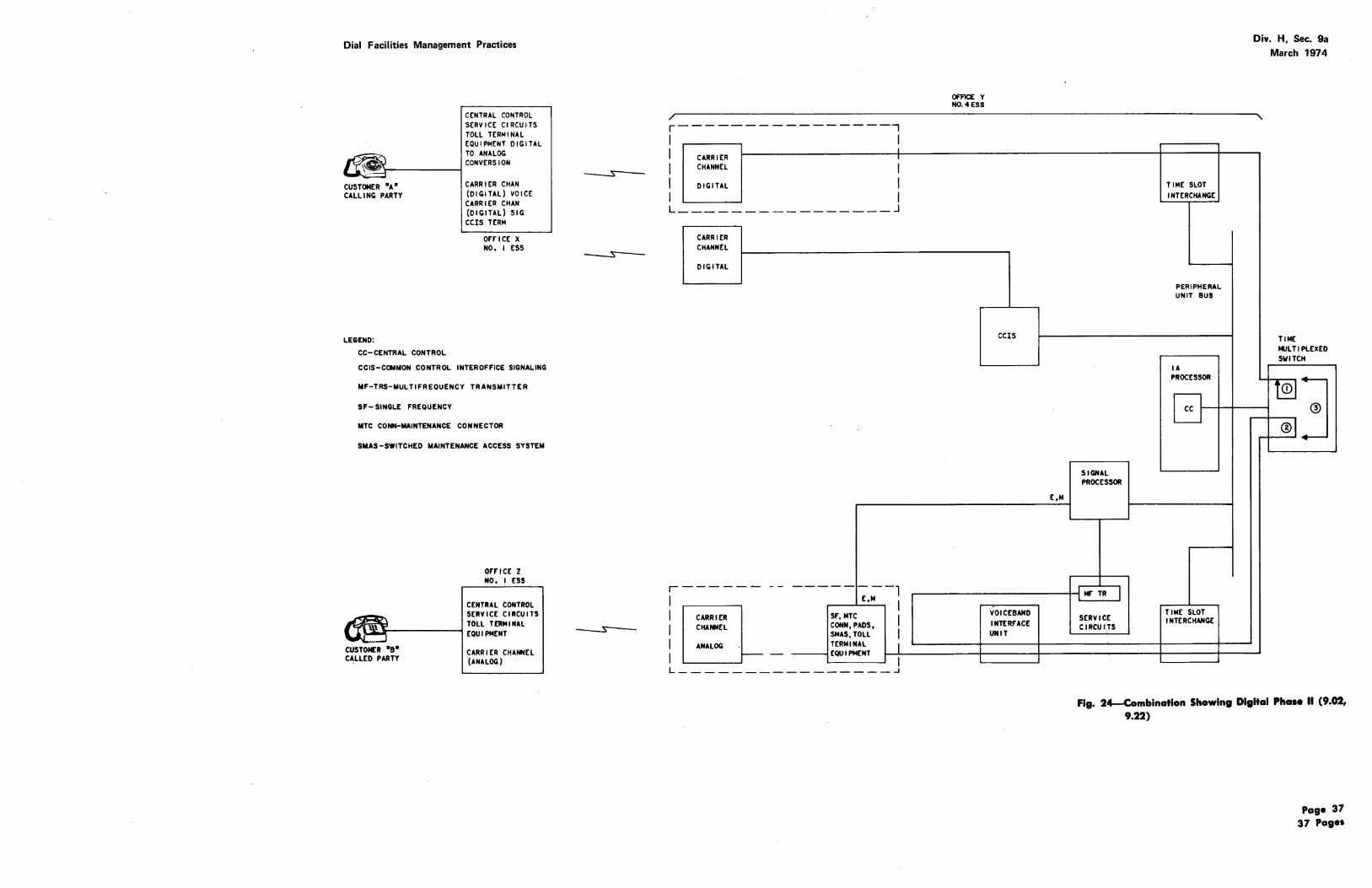
(d) Example 4: Combinations of voice and signaling arrangements (Fig. 24).
9.03 All four examples will use an intertoll tandem call. Customer A, the calling party, is
terminated on a No. 1 ESS office, office X. Each call will be completed to customer B, the called party. Customer B's telephone is terminated on another No. 1 ESS office, office Z, located in such a way that the call is tandemed through office Y, the No. 4 ESS office.
A. Example 1 (Fig. 21)
9.04 Customer A, the calling party, dials the necessary digits to establish a long distance
call and the local switching machine (No. 1 ESS), at office X, stores the dialed digits. The switching machine, at office X, causes battery to be applied to the M lead (E and M signaling) of the single frequency (SF) signaling unit associated with the MF trunk selected for use on this call. This seizure (battery on M lead) of the trunk transmits a "request for service" to the toll terminal equipment (SF unit) at the No. 4 ESS office, office Y.
9.05 The request for service is detected at the No. 4 ESS office by the scanning circuits
of a SP associated with the SF signaling leads of the trunk (E lead). The SP informs central control (of the 1A processor, via the peripheral unit bus) of the request for service on a specific trunk. The central control (CC) causes the switching network to establish a path between the incoming trunk and a multifrequency (MF) receiver; this i~ shown as switching path No. 1 (Fig. 21). The CC directs the SP associated with the selected MF receiver to collect the digits. The SP utilizes its signal distributor to transmit (via M lead of the SF unit) a "ready for digits" (start) signal over the trunk to the originating office, office X.
9.06 The originating office attaches an MF transmitter to the trunk and transmits the
necessary digits to the connected receiver at the No. 4 ESS office. This transmission is via the voice path of the No. 4 ESS switching network.
9.07 The SP utilizes its scanner to obtain the digit information from the MF receiver.
Page 13
Div. H, Sec. 9a March 1974
Digits are converted from MF frequencies into binary coded decimal information and passed on to central control. The CC translates the received digits (using stored programs) and determines the routing required. When the last digit has been received, the MF receiver is idled and network path No. 1 (Fig. 21) is released.
9.08 . After routing is determined, the CC directs the SP to seize a specific trunk (apply battery
to the M lead of its SF unit) to be used for the outgoing connection to the terminating office. This connection is shown as network path No. 2 in Fig. 21. Also a path from the incoming trunk to the outgoing trunk is reserved for later use. The process involved in establishing paths through the switching network is covered in "4. NETWORK" of this section.
9.09 The terminating office, office Z, recognizes the incoming request for service and attaches
an MF receiver to the trunk. The No. 1 ESS machine, at office Z, causes a "ready for digits" (start signal) to be transmitted back to the No. 4 ESS office via the signal leads of the associated SF unit.
9.10 At the No. 4 ESS office, this start signal is recognized by the SP and central control
is advised. The CC finds and establishes a network path between an MF transmitter and the selected outgoing trunk and then provides the SP with the digit information in binary coded decimal form. The SP utilizes the MF transmitter to transmit the necessary digits to the terminating office, office Z. Again, this transmission is via the voice path of the switching network. When outpulsing has been completed, CC idles the MF transmitter connection (network path 2 in Fig. 21) and establishes a network talking path previously reserved between the two trunks (path No. 3 in Fig. 21).
9.11 At office Z, the received digits are translated and ringing is applied to the called telephone;
an audible ring is returned to the calling customer A in office X. When customer B answers, office Z transmits an answer indication to the No. 4 ESS office. Office Z also removes ringing in both directions and connects the called party to the incoming trunk.
9.12 The "called party answer" indication is recognized by the SP at the No. 4 ESS
office and the CC is informed. Under direction
Page 14
Dial Facilities Management Practices
of the CC, the SP notifies the originating office that the called party has answered. The originating office, office X, connects the calling party to the outgoing trunk; the customers begin their conversation.
9.13 The SP now monitors the signal leads of both trunks to detect the call disconnect.
When the disconnect occurs, the signal processor will cause SF tone to be transmitted on both SF units thus releasing both trunks. The SP will also advise the CC to release the network talking connection.
B. Example 2 (fig. 22)
9.14 Customer A, the cailing party, dials the necessary digits to establish a long distance
call and the local switching machine (No. 1 ESS) at office X stores the dialed digits. The No. 1 ESS at office X locates an idle trunk to office Y and reserves this trunk in memory. The central control at office X transmits, via the peripheral unit bus, the tr,unk identity (label) and the associated signal and address data to its CCIS terminal. The CCIS encodes this information into formatted signal units (28 bit words) and passes the coded message to the data set. The data set utilizes a voice frequency (in this example, analog) carrier channel to transmit this information to the No. 4 ESS at office Y.
9.15 At office Y, the receiving data set accepts the data bit stream and presents individual
signals to the CCIS terminal. The CCIS terminal converts the data bits into binary encoded information in order to notify central control of the incoming "request for service" on a specific trunk. The central control, at office Y, reacts by establishing a path through the switching network (switching network path 1, Fig. 22) which connects the transmit and the receive directions of the specified trunk to form a closed loop for testing purposes.
9.16 While the No. 4 ESS machine translates the received signaling information using
stored programs, the No. 1 ESS machine, at office X, performs a voice path assurance test by sending and receiving a 2000-hertz tone through this "looped back" circuit. A message is sent to the No. 4 ESS indicating that there is continuity. The calling customer is connected to the outgoing trunk in office X.
Dial Facilities Management Practices
9.17 At office Y, routing is determined and an idle trunk to office Z is reserved in memory.
Central control, at office Y, sends the trunk identity, signaling, and address data to the CCIS terminal associated with the outgoing trunk. The CCIS unit, data set, and carrier channel transmit the coded message to office Z.
9.18 At office Z, the carrier channel, data set, and CCIS terminal are used to notify the
No. 1 ESS machine of the incoming call. When office Z receives all address digits, it returns an "address complete" message to office Y. The central control at office Z receives the indications and establishes the "loop back" for the No. 4 ESS to make its voice path assurance test. This test is shown as switching path No. 2 in Fig. 22. The No. 4 ESS sends a message to office Z indicating that the continuity check was successful. A path between the incoming and outgoing trunks is then established in the No. 4 ESS. The No. 1 ESS at office Z rings the called party (customer B) and supplies audible ringing to the originating customer.
9.19 When the called party's telephone goes "off-hook," the CCIS links are utilized to
advise office Y and office X that customer B has answered. Office Z establishes a talking path between the incoming trunk and the called customer B and releases ringing connections. The call is now in progress (switching network path No. 3 in Fig. 22).
9.20 Scanners at the two No. 1 ESS offices are now monitoring the customer's lines to
recognize the disconnect. When a disconnect occurs, the CCIS channels are used to notify the No. 4 ESS machine to release the connection.
C. Example 3 (Fig. 23)
9.21 Earlier discussions have explained that the No. 4 ESS is a time division switching
Div. H, Sec. 9a March 1974
system. This concept was developed to increase capacity, reliability, and speed, but its most important asset is its compatability with the growing digital carrier systems. Analog carrier systems are demodulated into individual voice frequency channels and then, on an individual circuit basis, reconverted to a digital basis for switching. With digital carrier systems, trunks terminating at a No. 4 ESS office can be input directly into the time slot interchange unit without the conversion from digital to analog and back to digital for switching. The first No. 4 ESS installations do not utilize this capability to its fullest. Instead, digital carrier systems are treated exactly like analog. This process (Phase I) and the equipment arrangements are shown in Fig. 23.
D. Example 4 (Fig. 24)
9.22 The ultimate objectives, ie, digital transmission being switched digitally and transmitted
digitally are shown in Fig. 24. It must be realized that most offices will not utilize digital carrier systems only; therefore, Fig. 24 illustrates the typical combinations of equipment that will be found in a No. 4 ESS office.
E. Local Tandem Operation
9.23 Intertoll calls were used with various facilities and signaling methods in the four examples
illustrating call processing in the No. 4 ESS. In addition, the No. 4 ESS is intended to be used as a metropolitan tandem switching system. Local tandem calls would be handled in the No. 4 ESS in a manner completely comparable to the intertoll examples. The emphasis on certain toll terminal equipment and operating requirements might change, eg, a local tandem might use considerably more digital terminal equipment and have more involved CAMA arrangements than an intertoll switching system.
Page 15/16
Dial Facilities Management Practices
LOCAL OFFICE
AMPUFICA liON STAGES
ANALOG TO
TOLL OFFICE
A- ANALOG CARRIER TRANSMI"SSION AND ANALOG SWITCHING
DIGITAL. TO DIGITAL CONVERTER ANALOG CONVERTER
B- DIGITAL TRANSMISSION AND ANALOG SWITCHING
JUL JlfL JlfL
C- DIGITAL TRANSMISSION AND DIGITAL SWITCHING
Fig. 1-Analog and Digital Transmission (2.06)
Div. H, Sec. 9a March 1974
LOCAL OFFICE
Page 17
Dial Facilities Management Practices Div. H, Sec. 9a March 1974
r------------------------------------1 : MAINTENANCE CIRCUIT TRUNK MACHINE I
OPERATIONS PROVISION OPERATIONS ADMINISTRATION I I CENTER CENTER CENllR CENTER I I ® I I 1: TERMINAL TRANSMISSION I NETWORK Ill EQUIPMENT SYSTEMS MANAGEMENT
CENTER CENTER CENTER
I L------------------------------------~
VOICE PATH I I ® ~----------------0 l r------------l I I CARRIER fACILITIES DIGROUP
I : I I 00 CLOCK 01 CLOCK 10 CLOCK II CLOCK CHAIN LOGIC I CHAIN LOGIC CHAIN LOGIC I CHAIN LOGIC
+ I + + I + CLOCK DRIVERS I CLOCK DRIVERS CLOCK DRIVERS I CLOCK DRIVERS
I I I
00 CONTROL I 01 CONTROL 10 CONTROL I II CONTROL PANEL +OVEN I PANEL + OVEN PANEL+ OVEN I PANEL+ OVEN
00 10 87A 87A
OSCILLATOR OSCILLATOR
01 I I 87A 87A
OSCILLATOR OSCILLATOR
I I 00 I 01 10 I II
POWER I
POWER POWER I
POWER CONVERTER CONVERTER CONVERTER CONVERTER
I I
00 I 01 10 I II
FUSE PANEL I FUSE PANEL FUSE PANEL I FUSE PANEL
Fig. 8-Network Clock ( 4.08}
Div. H, Sec. 9a March 1974
Page 24
Dial Facilities Management Practices
VOLTAGE { CONVERTER
VOLTAGE _J CONVERTEL
]
J
CONTROL PANEL
LOGIC CIRCUITRY
CONTROL PANEL
L c
OGIC IRCUITRY
Fig. 9-Program Store-Call Store Frame-Front View (5.05)
20A MEMORY
20A MEMORY
20A MEMORY
20A MEMORY
Div. H, Sec. 9a March 1974
Fig. 10-Pragram Store-Call Store Frame-Rear VIew (5.05, 5.10)
Page 25
Dial Facilities Management Practices
100 TRACK$ FULL ROTATION • 34 MILLISECONDS SECTOR 100 • MAINTENANCE ONLY
THIRTY -TWO 24-BIT 1-1-+-- WORDS PLUS 21 DATA
CHECK BITS
Fig. 11-0rganization of Data on Disk (5.12)
Div. H, Sec. 9a March 1974
Page 26
Dial Facilities Management Practices
I COMMUNITY I o I I I I I I I l I I I I I
CENTRAL CONTROL (ON-LINE)
I I I I L... ____________ _J
CENTRAL CONTROL (orr-uNO
Fig. 12-Basic Black Diagram of File Stores (5.13)
Div. H, Sec. 9a March 1974
Page 27
Dial Facilities Management Practices
BUS DRIVERS AND RECEIVERS
DC TO DC POWER PACKS
FUSES
INVERTER CIRCUIT PACKS
CONTROLLER LOGIC PACKS
(
[ (
[
AIR COMPRESSOR [
E5~0E5
Fig. 13-File Store Controller Frame (5.15)
DISK ASSEMBLY
\
\
-
l-/Q
!::::=,...--
/Q
Div. H, Sec. 9a March 1974
]
DC TO AC INVERTER
JAC INDUCTION MOTOR
Fig. 14-File Store Frame (5.15)
Page 28
Dial Facilities Management Practices
TAPE UNIT
f I I I I
AUXILIARY UNIT BUS 0
CONTROLLER 1-- [)0 I
I I I I I "
®
AUXILIARY BUS I
I DATA UNIT SELECTOR NO.O
I
OATA
f I I I I
LINK CONTROLLER
I DATA UNIT SELECTOR NO.I
I
I I I I
!
DATA UNIT BUS 0
~-··
DATA UNIT BUS I
t I I I I
ADDITIONAL CONTROL UNITS *
I I I I I l
LEGEND
Div. H, Sec. 9a March 1974
ASSOCIATED
r--- DATA UNITS+
* THE DATA UNIT SELECTOR PAIR CAN HAVE AS MANY AS 16 DATA UNITS ASSOCIATED WITH THE PAIR
t A DATA UNIT CAN EITHER BE A MAGNETIC TAPE TRANSPORT OR A DATA LINK TERMINAL
Fig. 15-Auxiliary Data System Block Diagram (5.17)
Page 29
Dial Facilities Management Practices
T TAPE TRANSPOR (KS-20571)
r'
......
@ 1&1
I]
@ [
lTAPT UNIT CONTROLLER
POWER CONTROL AND DISPL~Y PANEL
]
TRANSPORT LOCAL CONTROL PANEL
)TRANSPORT DOOR LATCH
]
TRANSPORT POWER SUPPLY DC TO DC INVERTER
Fig. 16-Tape Unit Frame (5.20)
\
~ _l
g I_Q
D D
IQ
Div. H, Sec. 9a March 1974
]
DATA UNIT SELECTOR CIRCUITRY
fig. 17-File Store Frame With Data Unit Seledor (5.20)
Page 30
Dial Facilities Management Practices
.;'"ii:"i:'" i"'z' ZI::I:ICI;ID CD a '• ''
CZJ a::J a ............... aaaa a:a:o:m a aaaaa
Div. H, Sec. 9a
March 1974
a aa
· ~~······ l aa aaaaa aa a . . ... .:..:.....:._. ~· -.:...:..:. ~ -. ~. -~ .... I .
Fig. 18--No. 4 ESS Maintenance Operation Center (5.22)
Page 31
Dial Facilities Management Practices
CONNECTOR UNIT CONNECTOR CONNECTOR UNIT UNIT
SCAN SCAN MATRIX MATRIX
so SCAN SCAN
APPLIQUE ACCESS ACCESS
SCAt.! MATRIX SCAIII MATRIX
SO MATRIX SO MATRIX
SO ACCESS SO ACCESS
SO MATRIX SO MATRIX
HEAT BAFFLE HEAT BAFFLE
DC-DC DC-DC DC-DC CONVERTER CONVERTERS CONVERTERS
FUSE PANEL FUSE PANEL FUSE PANEL
BAY~BAYI -2'2" 2'2"
DISTRIBUTE DISTRIBUTE a SCAN APPLIQUE FRAME MATRIX FRAME'
3' 3" 4' 4"
LEFT MATRIX
LEGEND:
PU- PERl PHERAL Ut.IIT
SO-SIGNAL DISTRIBUTOR
SP-SIGNAL PROCESSOR
PU BUS 0 PU BUS I
CONTROL CONTROL a a
MEMORY MEMORY
CONTROL CONTROL PANEL PANEL
oc-oc DC- DC CONVERTER CONVERTER
FUSE PANEL
BAYO~BAY I
2'·2" 2'2"--
SP FRAME
4' 4"
1024 MISC SCAN -----1-+-- --
1024 UNIV SCAN
so APPU QUE
1024 UNIV SCAN --1024 MISC· so
I 1024 UNIV SO
r--- -- ~-·-- ---1024 UNIV SO
BAY ~BAY I ~2· 2" 2'2'!.....-..e
DISTRIBUTE DISTRIBUTE a SCAN APPLIQUE FRAME MATRIX FRAME
3'3" 4'4"
RIGHT MATRIX
Div. H, Sec. 9a March 1974
]
CABLE COt.INECTOR
J SCAN MATRIX
J J J
SCAN ACCESS
SCAN MATRIX
so ACCESS
J SD MATRIX
] POWER
Fig. 19-Signal Processor I (6.06)
Page 32
Dial Facilities Management Practices Div. H, Sec. 9a March 1974
r---------------------------------------, I I
I
.... "' 1-
0
"' 1-<l u a
"' 0
0 5 I II
----"NAILED UP" CONNECTION
---BROADCAST CONNECTIONS
BUFFER A DECOR- BUFFER B 8X8 RELATOR SWITCH
I I I I I I I I I
\\\ I \\\ I ~ I .,.. _____ .J
RA I l I I II I 0 I 3 57 9 127
TIME MULTIPLEXED 8X8 BUFFER C RECOR-SWITCH SWITCH RELATOR
RA I I I 101 127
RA I I I 100 127
Fig. 20-Recordecl Announcements Dedicated TSI (7.07)
Page 33
Dial Facilities Management Practices
CUSTOMER •A" CAlli HG PARTY
LEGEND:
CENTRAL CONTROL SERVICE CIRCUITS TOLL TERMINAL EQUIPMENT
CARRIER CHANNEL (ANALOG)
OF"F"IC£ X NO. I ESS
SMAS- SWITCHED MAINTENANCE ACCESS SYSTEM MTC CONN- MAINTENANCE CONNECTOR SF- SINGLE FREQUENCY MF- MULTIFREOUENCY CC-CENTRAL CONTROL MF TRS- MULTIFREOUENCY TRANSMITTER.
OF"F"IC£ Z NO. I ESS
CENTRAL CONTROL SERVICE CIRCUITS TOLL TERMINAL
\...Oiii.J\,---------1 EQU I PMEHT
CUSTOMER •a• CALLED PARTY
CARRIER CHANNEL (ANALOG)
CARRIER CHANNEL
ANALOG
CARRIER CHANNEL
ANALOG
TOLL ---TERMINAL -EQUIPMENT VOIC£8AND PADS, SMAS, INTERF"AC£ MTC CONN,SF UNIT
£,M
SF; MTC CONN, VOICEBAND PADS, SMAS INTERF"ACE
TOLL UNIT
TERMINAL EQUIPMENT --
OFFICE Y NO. 4 ESS
£,M
E,M
STAGE 0
STAGE3 SERVICE CIRCUITS TIM£ SLOT
INTERCHANGE
MF RECEIVER
PERIPHERAL UNIT BUS
lA PROCESSOR
SIGNAl PROCESSOR
r-- cc
MF" TRS I TIME SLOT
SERVICE INTERCHANGE CIRCUITS
Div. H, Sec. 9a March 1974
TIME MUL Tl PLEX£0 SWITCH
STAGEI +--
CDj STAGE2 0
' ®l +--
Fig. 21-Analog Carrier Systems Utilizing Single Frequency Units (9.02, 9.05, 9.07, 9.08, 9.10)
CEN'I'RAL CONTROL SERVICE CIRCUITS TOLL TERMINAL [.QUI PMENT DIGITAL TO ANALOG CONVERSION CARRIER CHANNEL (DIGITAL) VOICE CARRIER CHANNEL (DIGITAL) SIGNAL CCIS TERMINAL
OFF' ICE X NO. I ESS
SMAS- SWITCHED MAINTENANCE ACCESS SYSTEM
MTC CONN- MAINTENANCE CONNECTOR
PU BUS- PERIPAERAL UNIT BUS
CC- CENTRAL CONTROl.
CCIS- COMMON CONTROL INTEROFFICE SIGNALING
SF- SINGLE FREQUENCY
CUSTOMER •e• CALLED PARTY
OF'F'ICE Z 110. I ESS
CENTRAL CONTROl SERVICE CIRCUITS TOLL TERMINAL EQUIPMENT DIGITAL TO ANALOG CONVERSION CARRIER CHANNEL (DIGITAL) VOICE CARRIER CHANNEL (DIGITAl) SIGNAL CCIS TERMINAL
~-------------------,
I I I I I I L
I I I I I
f-- TOLL CARRIER DIGITAL TO CHANNEL ANALOG TERMINAL
I EQIIIPMENT
DIGITAL CONVERSION PADS, SMAS, I MTC CONN I
-------------------~
CARRIER DIGITAL TO CHANNEL ANALOG -DIGITAL CONVERSION
CARRIER DIGITAl TO CHANNEL ANALOG
1---
DIGITAL CONVERSION
------------- ------, CARRIER DIGITAl TO PADS, SMAS, I CHANNEL ANALOG MTC CONN !
TOLL I DIGITAL CONVERSION T!:RMINAl I ~ EQUIPMENT L ___________________ ~
OFFICE Y N0.4ESS
VOICEBAND INTERFACE UNIT
DATA SET
I CCIS TERMINAL
CCIS TERMINAL
I DATA SET
VOICEBAND INTERF'ACE UNIT
SERVICE CIRCUITS
TONES l
SIGNAL .....__ PROCESSOR
TONES l SERVICE CIRCUITS
TIME SLOT INTERCHANGE
PU BUS
lA PROCESSSOR
cc
TIME SLOT INTERCHANGE
Div. H, Sec. 9a March 1974
TIME MULTIPLEX ED SWITCH
~3 ®
L®l
fig. 23--Digltal Carrier Systems, Application During Phase I, Utilizing Common Channel lnteroHice Signaling (9.02, 9.21)
Page 36
Dial Facilities Management Practices
r--------1 CUSTOMER "A" CAlliNG PARTY
LEGEND:
CC-CENTRAL CONTROL
CENTRAL CONTROl SERVICE CIRCUITS TOLL TERMINAL EQUIPMENT DIGITAL TO ANALOG CONVERSION
CARRIER CHAN (DIGITAL) VOICE CARRIER CHAN (DIGITAL) SIG CCIS TERM
OF'FICE X NO. I ESS
CCIS-COMMON CONTROL INTEROFFICE SIGNALING
MF-TRS-MULTIFREOUENCY TRANSMITTER
SF- SINGLE FREQUENCY
MTC CONN-MAINTENANCE CONNECTOR
$MAS-SWITCHED MAINTENANCE ACCESS SYSTEM
OF'rtCE Z NO. I ESS
CENTRAL CONTROL SERVICE CIRCUITS TOll TERMINAL EQUIPMENT
CUSTOMER "B" CARRIER CHANNEl CALLED PARTY (ANALOG)
r----------------~
I I I CARRIER
I
I CHANNEL I I DIGITAl I I I L ________________ J
r-I I I
CARRIER CHANNEL
DIGITAL
-----
CARRIER CHANNEl
-- --------, E,M I
sr, MTC I CONN, PADS, SMAS,TOll I
OFFICE y N0.4ESS
CCIS
E,M
SIGNAL PROCESSOR
.------------+--1 MF' TR I VOICEBAND INTERFACE UNIT
SERVICE CIRCUfTS
TIME SLOT INTERCHANGE
PERIPHERAL UNIT BUS
Div. H, Sec. 9a March 1974
TIME MULTIPLEXED SWITCH
lA PROCESSOR
cc t---t-+-~ ~ :1 ®1.]
TIME SLOT INTERCHANGE
I ANALOG
I 1-----TERMINAL I
----!EQUIPMENT t-7-------t-----t----------+----+--_J L ________________ j
Fig. 24--Combinatlon Showing Digital PhaH II (9.02, 9.22)