SY-6IWM/L Motherboard **************************************************** Pentium ® III, Pentium ® II & Celeron Processor supported FW82810 AGP/PCI/AMR 66/100 MHz Front Side Bus supported Micro ATX Form Factor **************************************************** User's Manual
Trademarks:Soyo is the registered trademark of Soyo Computer Inc. All trademarks are theproperties of their owners.
Product Rights:All names of the product and corporate mentioned in this publication are used foridentification purposes only. The registered trademarks and copyrights belong totheir respective companies.
Copyright Notice:All rights reserved. This manual has been copyrighted by Soyo Computer Inc. Nopart of this manual may be reproduced, transmitted, transcribed, translated into anyother language, or stored in a retrieval system, in any form or by any means, suchas by electronic, mechanical, magnetic, optical, chemical, manual or otherwise,without permission in writing from Soyo Computer Inc.
Disclaimer:Soyo Computer Inc. makes no representations or warranties regarding the contentsof this manual. We reserve the right to amend the manual or revise thespecifications of the product described in it from time to time without obligation tonotify any person of such revision or amend. The information contained in thismanual is provided to our customers for general use. Customers should be awarethat the personal computer field is subject to many patents. All of our customersshould ensure that their use of our products does not infringe upon any patents. It isthe policy of Soyo Computer Inc. to respect the valid patent rights of third partiesand not to infringe upon or to cause others to infringe upon such rights.
Restricted Rights Legend:Use, duplication, or disclosure by the Government is subject to restrictions setforth in subparagraph (c)(1)(ii) of the Rights in Technical Data and ComputerSoftware clause at 252.277-7013.
About This Guide:This Quick Start Guide can help system manufacturers and end users in setting upand installing the Motherboard. Information in this guide has been carefullychecked for reliability; however, to the correctness of the contents there is noguarantee given. The information in this document is subject to amend withoutnotice.
For further information, please visit our Web Site on the Internet. The address is"http://www.soyo.com.tw".
Edition: October 1999Version 1.06IWM/L SERIAL
FCC Tested To ComplyWith FCC Standards
FOR HOME OR OFFICE USE
POST CONSUMERRECYCLED PAPER100%
Table of Contents SY-6IWM/L
iii
Table of ContentsCHAPTER 1 MOTHERBOARD DESCRIPTION ...................................1
1-1 INTRODUCTION............................................................11-2 KEY FEATURES .............................................................11-3 HANDLING THE MOTHERBOARD ..............................31-4 ELECTROSTATIC DISCHARGE PRECAUTIONS .........31-5 SY-6IWM/L MOTHERBOARD LAYOUT.......................41-6 SY-6IWM/L MOTHERBOARD COMPONENTS ............51-7 CHIPSET .........................................................................71-8 I/O INTERFACE CONTROLLER ..................................131-9 AUDIO SUBSYSTEM ...................................................151-10 HARDWARE MONITOR...............................................161-11 WAKE ON LAN TECHNOLOGY..................................16
3-5 INTEGRATED PERIPHERALS .....................................653-6 POWER MANAGEMENT SETUP ................................693-7 PNP/PCI CONFIGURATION SETUP.............................723-8 PC HEALTH STATUS....................................................753-9 LOAD OPTIMIZED DEFAULTS...................................773-10 LOAD FAIL-SAFE DEFAULTS.....................................783-11 SUPERVISOR PASSWORD...........................................793-12 USER PASSWORD........................................................803-13 IDE HDD AUTO DETECTION .....................................81
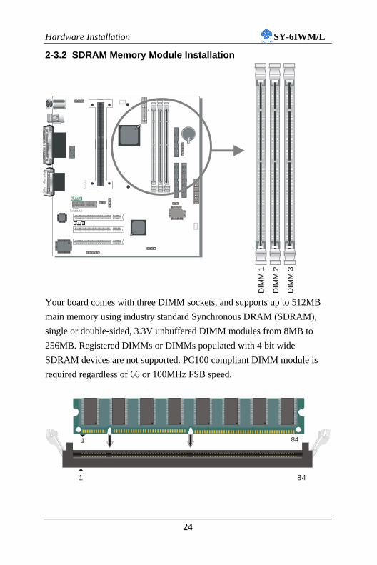
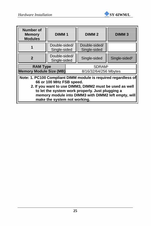
RAM Type SDRAM¹Memory Module Size (MB) 8/16/32/64/256 Mbytes
Note: 1. PC100 Compliant DIMM module is required regardless of66 or 100 MHz FSB speed.
2. If you want to use DIMM3, DIMM2 must be used as wellto let the system work properly. Just plugging amemory module into DIMM3 with DIMM2 left empty, willmake the system not working.
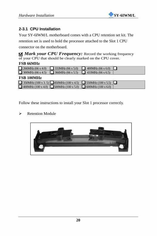
Hardware Installation SY-6IWM/L
26
2-3.3 Motherboard Connector
2-3.3.1 IDE Device Installation (HDD, CD-ROM)
This Motherboard offers two primary and secondary IDE device
connectors (IDE1, IDE2.) It can support up to four high-speed HDD or
CD-ROM.
Connect one side of the 40-pin flat cable to the IDE device (HDD or CD-
ROM) and plug the other end to the primary (IDE1) or secondary (IDE2)
directionally keyed IDE connector on the Motherboard.
This Motherboard can support up to four ATA 33/66 IDE devices.
ITE
IDE 2 IDE 1Pin -1
SecondaryIDE
PrimaryIDE
1
1
39
3940-pin
ATA 66Flat Cable
80-Conductor
Hardware Installation SY-6IWM/L
27
2-3.3.2 Floppy Drive Installation
The system supports 5 possible floppy drive types: 720 KB, 1.2 MB,
1.44 MB, 2.88 MB, and LS-120. In addition, this Motherboard supports a
3-mode (720KB/1.2MB/1.44MB) floppy commonly used in Japan.
Connect one side of the 34-pin flat cable to the floppy drive and plug the
other end to the floppy drive connector on the Motherboard.
This Motherboard can support up to 2 floppy drives.
ITE
1
1
33
33
FDCPin -1
Floppy DriveConnector
Hardware Installation SY-6IWM/L
28
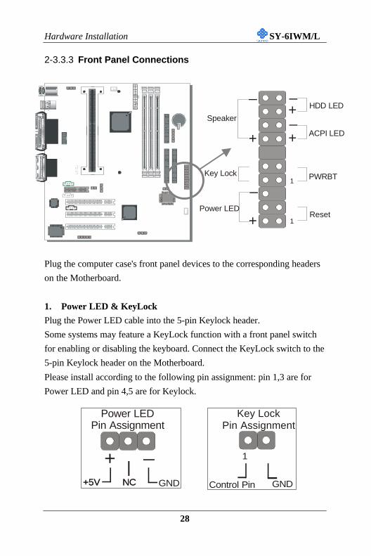
2-3.3.3 Front Panel Connections
Plug the computer case's front panel devices to the corresponding headers
on the Motherboard.
1. Power LED & KeyLock
Plug the Power LED cable into the 5-pin Keylock header.
Some systems may feature a KeyLock function with a front panel switch
for enabling or disabling the keyboard. Connect the KeyLock switch to the
5-pin Keylock header on the Motherboard.
Please install according to the following pin assignment: pin 1,3 are for
Power LED and pin 4,5 are for Keylock.
ITE
Power LEDPin Assignment
+5V+5V GND
+ _
NCNC
Key Lock Pin Assignment
Control Pin GND
1
Power LED
Key Lock
Speaker
Reset
PWRBT
ACPI LED
HDD LED
++
++
_
_
_
_
1
1
Hardware Installation SY-6IWM/L
29
2. Reset
Plug the Reset push-button cable into the 2-pin Reset header on the
Motherboard. Pushing the Reset button on the front panel will cause the
system to restart the boot-up sequence.
3. Speaker
Attach the 4-pin PC speaker cable from the case to the Speaker header on
the Motherboard.
4. ACPI LED
Connecting the 2-pin ACPI LED cable to the corresponding ACPI LED
header will cause the LED to light whenever the system is in ACPI mode.
The manufacturer has permanently set this Motherboard in ACPI mode
due to most hardware and software compliance to ACPI mode.
Reset Pin Assignment
Power Good GND
1
Speaker Pin Assignment
+ _
+5V Speaker outNC NC
ACPI LED Pin Assignment
+ _
LED Anode LED Cathode
Hardware Installation SY-6IWM/L
30
5. IDE LED
Attach the 2-pin IDE device LED cable to the corresponding IDE LED
header on the Motherboard. This will cause the LED to lighten when an
IDE (HDD, CD-ROM) device is active.
6. ATX Power On/Off Switch
Attach the 2-pin momentary type switch to the PWRBT header for turning
On or Off your ATX power supply.
HDD LED Pin Assignment
+ _
LED Anode LED Cathode
PWRBT Pin Assignment
Power On/Off GND
1
Hardware Installation SY-6IWM/L
31
2-3.3.4 Back Panel Connections
All external devices such as the PS/2 keyboard, PS/2 mouse, printer,
modem, USB can be plugged directly onto the Motherboard back panel.
Only after you have fixed and locked the Motherboard to the computer
case can you start connecting the external peripheral devices.
When connecting an external device, use the following figure to locate and
identify which back panel connector to plug the device to.
ITE
COM 1
VGA
PRT
USB 1 USB 2
PS/2 KBConnector
PS/2 MouseConnector
Game Port
LINE-OUT
LINE-IN
MIC JACK
Hardware Installation SY-6IWM/L
32
1. Parallel Port PRT
This parallel port is used to connect the printer or other parallel devices.
Plug the parallel device cable into the 25-pin female connector located at
the rear panel of the Motherboard.
Plug the keyboard jack directly into the 6-pin female PS/2 keyboard
connector located at the rear panel of the Motherboard.
2. PS/2 Mouse
Similarly, plug the mouse jack directly into the 6-pin female PS/2 mouse
connector.
Pin5KBD Clock
Pin6NC
Pin3GND
Pin1KBD DATA
Pin2NC
Pin4VCC
Pin6NC
Pin5Mouse Clock
Pin4VCC
Pin3GND
Pin2NC
Pin1Mouse DATA
PS/2 KeyboardConnector
PS/2 MouseConnector
USB2
USB1 VGA Connector
Printer Connector
COM 1 Connector
Joystick
LINE-OUTLINE-IN
MIC
Hardware Installation SY-6IWM/L
33
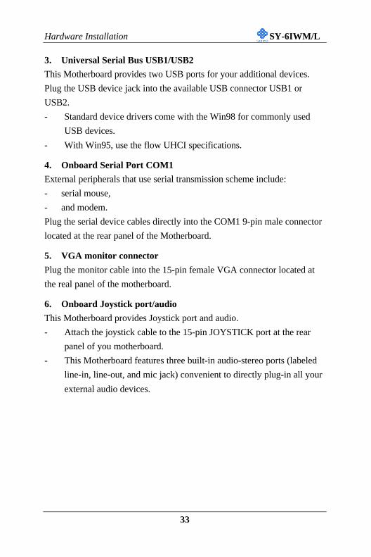
3. Universal Serial Bus USB1/USB2
This Motherboard provides two USB ports for your additional devices.
Plug the USB device jack into the available USB connector USB1 or
USB2.
- Standard device drivers come with the Win98 for commonly used
USB devices.
- With Win95, use the flow UHCI specifications.
4. Onboard Serial Port COM1
External peripherals that use serial transmission scheme include:
- serial mouse,
- and modem.
Plug the serial device cables directly into the COM1 9-pin male connector
located at the rear panel of the Motherboard.
5. VGA monitor connector
Plug the monitor cable into the 15-pin female VGA connector located at
the real panel of the motherboard.
6. Onboard Joystick port/audio
This Motherboard provides Joystick port and audio.
- Attach the joystick cable to the 15-pin JOYSTICK port at the rear
panel of you motherboard.
- This Motherboard features three built-in audio-stereo ports (labeled
line-in, line-out, and mic jack) convenient to directly plug-in all your
external audio devices.
Hardware Installation SY-6IWM/L
34
2-3.3.5 Other Connections
1. Serial Port COM2
In addition to the onboard serial connector COM1 located at the rear
panel, your Motherboard comes with a second serial port COM2 equipped
with a flat cable and external connector.
The Motherboard package includes one serial port flat cable with a 9-pin
connector.
Plug the 9-pin end of the flat cable into the COM2 serial connector on the
Motherboard, as shown in the figure below, then fix the external 9-pin
connector to the rear panel of the computer case. Then plug your serial
device cable directly into this 9-pin male connector located at the back of
your computer.
COM 2
9-pin serialflat cable
9-pin male externalserial connector
Hardware Installation SY-6IWM/L
35
2. Wake-On-LAN (WOL)
Attach the 3-pin connector from the LAN card which supports the Wake-
On-LAN (WOL) function to the JP44 header on the Motherboard. This
WOL function lets users wake up the connected computer through the
LAN card.
Please install according to the following pin assignment:
Wake-On-LANJP44 Pin Assignment
MP-Wake-up
GND
5VSB 1
2
3
Hardware Installation SY-6IWM/L
36
3. Infrared (IR1)
Plug the 5-pin infrared device cable to the IR1 header. This will enable the
infrared transfer function. This Motherboard meets both the ASKIR and
HPSIR specifications.
Please install according to the following pin assignment:
4. CD Line-in (J9)
This Motherboard provides two CD-Line in connectors. Please connect the
4-pin audio cable from your CD-ROM drive to either J9. (It fits in only
one, depending on the cable that came with your CD-ROM drive)
Please install according to the following pin assignment:
Serial Infrared (IR1) ConnectorIR1 Pin Assignment
1 2 3 4 5VCC
IRRXGND
IRTX
CD-IN: J9
RightLeft
GNDGND
1 2 3 4
Hardware Installation SY-6IWM/L
37
5. Aux-in (J10)
For Auxiliary Audio devices (1.0Vrms typ.).
6. Phone-in (J11)
Connect to modem sound connector.
AUX-IN: J10
Right
Left
GND
GND
1
2
3
4
PHONE-IN: J11
In
MonoGND
GND
1 2 3 4
Hardware Installation SY-6IWM/L
38
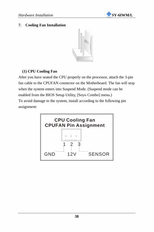
7. Cooling Fan Installation
(1) CPU Cooling Fan
After you have seated the CPU properly on the processor, attach the 3-pin
fan cable to the CPUFAN connector on the Motherboard. The fan will stop
when the system enters into Suspend Mode. (Suspend mode can be
enabled from the BIOS Setup Utility, [Soyo Combo] menu.)
To avoid damage to the system, install according to the following pin
assignment:
CPU Cooling FanCPUFAN Pin Assignment
SENSOR12VGND
1 32
Hardware Installation SY-6IWM/L
39
(2) Chassis Cooling Fan
Some chassis also feature a cooling fan. This Motherboard features a
CHAFAN connector to provide 12V power to the chassis fan. Connect the
cable from the chassis fan to the CHAFAN 3-pin connector. Install
according to the following pin assignment:
Note: CPU cooling fan must be installed to prevent CPU from
overheating and ensure system stability. Chassis cooling fan is
optional, depending on whether there is cooling fan in your chassis.
Chassis Cooling FanCHAFAN Pin Assignment
SENSOR12VGND
1 32
Hardware Installation SY-6IWM/L
40
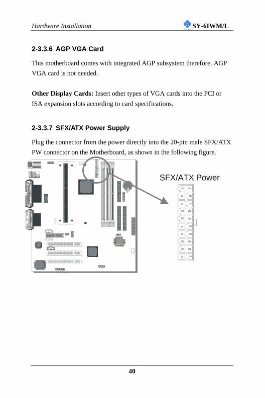
2-3.3.6 AGP VGA Card
This motherboard comes with integrated AGP subsystem therefore, AGP
VGA card is not needed.
Other Display Cards: Insert other types of VGA cards into the PCI or
ISA expansion slots according to card specifications.
2-3.3.7 SFX/ATX Power Supply
Plug the connector from the power directly into the 20-pin male SFX/ATX
PW connector on the Motherboard, as shown in the following figure.
ITE
SFX/ATX Power
Hardware Installation SY-6IWM/L
41
3.3V
-12V
GND
PS-ON
GND
GND
GND
-5V
5V
5V
3.3V
3.3V
GND
5V
GND
5V
GND
PW-OK
5VSB
12V
SFX/ATX Power
Warning: Follow these precautions to preserve your
Motherboard from any remnant currents when connecting to
power supply:
Turn off the power supply and unplug the power cord of the
power supply before connecting to PW connector.
This motherboard requires a power supply, that meets the SFX 1.1 or ATX
2.03 specifications. Make sure the power supply can support at least
720mA on the 5V Standby lead. It you use the Wake-On-LAN (WOL)
function.
Please install the SFX/ATX power according to the following pin
assignment:
Ø Pay special care to the directionality.
Hardware Installation SY-6IWM/L
42
2-3.3.8 AMR (Audio Modem Riser)Connector
This motherboard supports AMR (Audio-Modem Riser) slot that
facilitates audio or modem riser card expansion. Since AC97 audio codec
is built-in down on the motherboard, only “Secondary” mode modem riser
(MR) card can be used on the AMR slot.
ITE
Hardware Installation SY-6IWM/L
43
2-3.4 Jumper Setting
Step 1. Enable/Disable Power-On by Keyboard (JP1)You may choose to enable the Power-On through Keyboard function by
shorting pin 1-2 on jumper JP1; or short pin 2-3 to disable this function.
Power-On byKeyboard Enable Disable
JP1 Setting
Short pin 1-2 toenable the
Power-On byKeyboardfunction.
Short pin 2-3and the Power-On by Keyboard
function isdisabled.
Important: When using the Power-On by Keyboard function, pleasemake sure the ATX power supply is able to provide at least 720mA onthe 5V Standby lead (5VSB) in order to meet the standard ATXspecification.
Step 2. Set JP9 for hardware Write-ProtectThis jumper sets FWH (Firm Ware Hub or BIOS) Write-protect when
open, Short JP9 ONLY when the BIOS needs to be upgraded.
The Hardware Write-Protect Locked Unlocked
JP9 Setting open JP9 short JP9
Don’t make any change on the factory default setting of JP2
& JP3. Any change on the JP2 & JP3 may cause malfunction
or components damage.
JP3 JP2
Short JP3 Open JP2
1 2 31 2 3
1 21 2
1 2 1 2 3
Hardware Installation SY-6IWM/L
44
2-3.5 CMOS Clearing (JP5)
After you have turned off your computer, clear the CMOS memory by
momentarily shorting pins 2-3 on jumper JP5, for a few seconds. Then
restore JP5 to the initial 1-2 jumper setting in order to recover and retain
the default settings.
Jumper JP5 can be easily identified by its white colored cap.
CMOSClearing Clear CMOS Data Retain CMOS Data
JP5 SettingShort pin 2-3 forat least 5 seconds toclear the CMOS
Short pin 1-2to retain newsettings
Note: You must unplug the ATX power cable from the ATX powerconnector when performing the CMOS Clear operation.
2-3.6 Power On
You have now completed the hardware installation of your Motherboard
successfully.
1. Turn the power on
2. To enter the BIOS Setup Utility, press the <DEL> key while the system
is performing the diagnostic checks,
Note: If you have failed to enter the BIOS, wait until the boot up
sequence is completed. Then push the RESET button and press
<DEL> key again at the beginning of boot-up, during diagnostic
checks.
1 2 31 2 3
Hardware Installation SY-6IWM/L
45
Repeat this operation until you get the following screen.
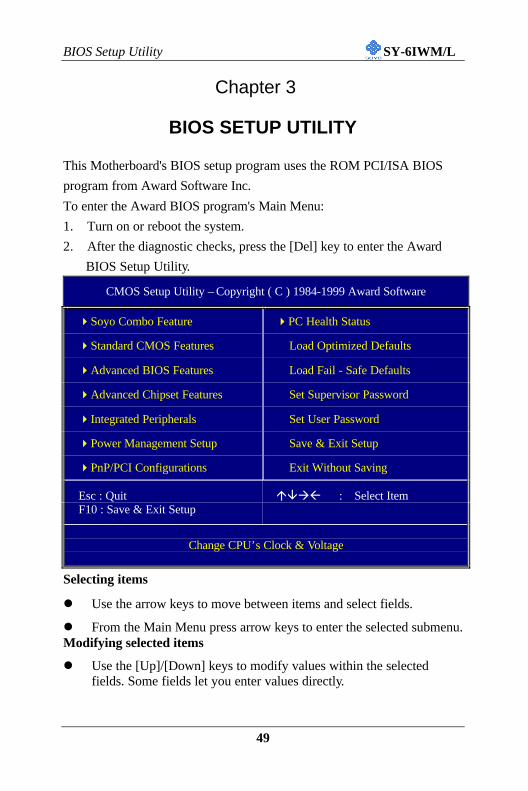
3. The BIOS Setup screen appears:
CMOS Setup Utility – Copyright ( C ) 1984-1999 Award Software
4Soyo Combo Feature 4PC Health Status
4Standard CMOS Features Load Optimized Defaults
4Advanced BIOS Features Load Fail - Safe Defaults
4Advanced Chipset Features Set Supervisor Password
Select the host clock of your Slot 1processor among these values.Note: For the 810 chipset, 66and 100 MHz host clockfrequencies are acceptable.However, the system stability isnot guaranteed for otherfrequencies due to thelimitations of this chipset.
CPU Ratio After you have selected the host clock, choose the rightmultiplier for the CPU. Options are: [2, 2.5, 3., 3.5, 4, 4.5, 5,5.5,6,6.5,7.0,7.5,8.0]. The CPU frequency is then defined as[host clock freq.]x[multiplier], and should the workingfrequency of your Pentium® III, Pentium® II & Celeronprocessor.
This item sets the strengthof the buffer that drives theaddress section of thememory bus. Change thesetting only if you are anexperienced user.
3-1.3 L2 Cache MemorySetting Description Note
Def 08 DefaultCPU L2 LatencyAdjust Set 01 ~
Set 15
The speed of the L2 cache that isintegrated into the CPU can be setthrough this item. Do not changethis item unless ;you are anexperienced user.
DisabledCPU L2 CacheECC Checking Enabled
This option activates the CPU L2cache ECC checking function. Default
BIOS Setup Utility SY-6IWM/L
54
3-1.4 Processor Number Feature SettingSetting Description Note
DisabledProcessorNumberFeature
EnabledSetting this item to enabled will allowapplication programs to read the ID-code in your Pentium III CPU, disablingthis item will not allow any program toread the CPU ID code.
Default
3-1.5 Quick Power On Self Test SettingSetting Description Note
DisabledQuick Power OnSelf Test Enabled Provides a fast POTS at boot-up. Default
3-1.6 System Boot Control SettingsSystem BootControl Settings
Setting Description Note
Floppy HDD-1LS/ZIP HDD-2HDD-0 HDD-3SCSI LAN
First/Second/ThirdBoot Device
CDROM Disabled
Select Your Boot DevicePriority
DisabledBoot OtherDevice Enabled
Select Your Boot Device PriorityDefault
DisabledAC97Audio/Modem auto
This item allows you to decide toauto/disable the 810 chipset familyto support AC97 Audio/ Modem.
Default
Onboard Audio Disabled This item is fixed to disabled.
BIOS Setup Utility SY-6IWM/L
55
3-1.7 Others OptionalSetting Description Note
Password Enables you to wake-up thesystem by entering a password atthe keyboard.
Hot KEY You can wake-up the system bypressing the key combination ofyour choice (Ctrl-F1~F12).
Mouse LeftMouse Right
Enables waking up the system bypressing either the right or leftmouse button.
BUTTON-ONLY Disables the Wake-Up byKeyboard function.
Default
POWER ONFunction
Keyboard 98
If [POWER ON Function] is set to [Password]
KB Power ONPassword
Enter (yourpassword)
Set the password that will wake-up yoursystem.
If [POWER ON Function] is set to [Hot Key]
Hot Key PowerON
Ctrl-F1~F12
Choose the key combination that will wake-up the system. [Ctrl-F1 to Ctrl-F12]
Instant-off DefaultSoft-Off byPWR-BTTN Delay 4
Sec.Turns off the system power 4seconds after pushing the powerbutton.
Disabled If enabled any PCI interrupt willwake up the system.
DefaultWake-Up byPCI card
Enabled
Disabled The system ignores the alarm. DefaultResume byAlarm Enabled Set alarm to power on the system by
the date (1-31) or time (hh:mm:ss).If the date is set to [0], the systemwill self-power on by alarmeveryday at the set time.
BIOS Setup Utility SY-6IWM/L
56
3-2 STANDARD CMOS SETUPSelect the [STANDARD CMOS SETUP] option from the Main Menu and
press [Enter] key.
CMOS Setup Utility – Copyright ( C ) 1984-1999 Award SoftwareStandard CMOS Features
Date (mm:dd:yy) Fri, Jan 1 1999Time (hh:mm:ss) 1 : 22 : 12
Item Help
4 IDE Primary Master Press Enter None4 IDE Primary Slave Press Enter None4 IDE Secondary Master Press Enter None4 IDE Secondary Slave Press Enter None
Drive A 1.44M, 3.5 in.Drive B NoneFloppy 3 Mode Support Disabled
Video EGA/VGAHalt On All Errors
Base Memory 640KExtended Memory 30720KTotal Memory 31744K
Menu Level 4
áâàß:Move Enter:Select +/-/PU/PD:Value F10:Save ESC:Exit F1:General Help
Protection EnabledIf set to enabled, the ParagonAnti-Virus. Function will scanyour boot drive for bootvirusses. If a boot virus isdetected, the BIOS will displaya warning message.
After you have completed the changes, press [Esc] and follow the
instructions on your screen to save your settings or exit without saving.
The following table describes each field in the Advanced Chipset Features
Menu and how to configure each parameter.
BIOS Setup Utility SY-6IWM/L
64
CHIPSET FEATURES SETUPCHIPSETFEATURES
Setting Description Note
SDRAM CASLatency Time
23
Use the default settingDefault
SDRAM CycleTime Tras/Trc
5/76/8
Use the default settingDefault
SDRAM RAS-to-CAS Delay
32
Use the default settingDefault
DisabledSystem BIOSCacheable Enabled The ROM area F0000H-FFFFFH is
cacheable.Default
DisabledVideo BIOSCacheable Enabled The video BIOS C0000H-C7FFFH is
cacheable.Default
Disabled DefaultMemory HoleAt 15M-16M Enabled Some interface cards will map their
ROM address to this area. If thisoccurs, select [Enabled] in this field.
DelayedTransaction
Enabled Use the default setting Default
Disabled DefaultSpreadSpectrum Enabled When using Spread Spectrum
Modulated 1.5% or 6% for FCC orDOC testing.
100MHzLocal MemoryFrequency 133MHz
This item allows the user to set thefrequency the memory runs at. If this itemis set to 100MHz, make sure to use PC-100 compliant DIMM modules. If thisitem is set to 133Mhz, PC-133 compliantmodules have to be used. Setting this itemto a higher frequency than is supported byyour SDRAM DIMM modules may leadto system crashes.Note: Only the 810E chipset supportsthis Feature.
Default
BIOS Setup Utility SY-6IWM/L
65
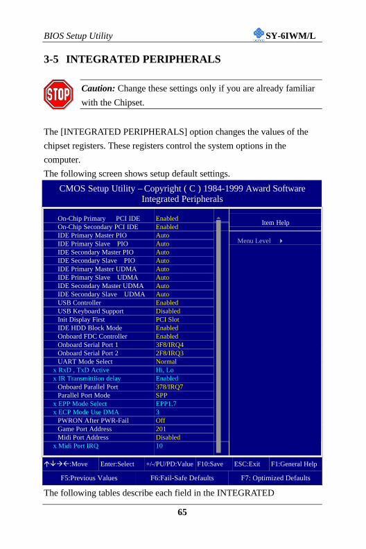
3-5 INTEGRATED PERIPHERALS
Caution: Change these settings only if you are already familiar
with the Chipset.
The [INTEGRATED PERIPHERALS] option changes the values of the
chipset registers. These registers control the system options in the
computer.
The following screen shows setup default settings.
CMOS Setup Utility – Copyright ( C ) 1984-1999 Award SoftwareIntegrated Peripherals
On-Chip Primary PCI IDE Enabled 5
On-Chip Secondary PCI IDE EnabledItem Help
IDE Primary Master PIO AutoIDE Primary Slave PIO AutoIDE Secondary Master PIO AutoIDE Secondary Slave PIO AutoIDE Primary Master UDMA AutoIDE Primary Slave UDMA AutoIDE Secondary Master UDMA AutoIDE Secondary Slave UDMA AutoUSB Controller EnabledUSB Keyboard Support DisabledInit Display First PCI SlotIDE HDD Block Mode EnabledOnboard FDC Controller EnabledOnboard Serial Port 1 3F8/IRQ4Onboard Serial Port 2 2F8/IRQ3UART Mode Select Normal
x RxD , TxD Active Hi, Lox IR Transmittiion delay Enabled
Onboard Parallel Port 378/IRQ7Parallel Port Mode SPP
x EPP Mode Select EPP1.7x ECP Mode Use DMA 3
PWRON After PWR-Fail OffGame Port Address 201Midi Port Address Disabled
x Midi Port IRQ 10 6
Menu Level 4
áâàß:Move Enter:Select +/-/PU/PD:Value F10:Save ESC:Exit F1:General Help
Choose serial port 1 &2's I/O address.Do not set port 1 & 2 tothe same address exceptfor Disabled or Auto.
Normal DefaultIrDA
UART Mode Select
ASKIR
The second serial portoffers these InfraRedinterface modes.
If [UART Mode Select] is set to [IrDA]/[ASKIR]
RxD, TxD Active Hi, Hi, Lo, Lo,Lo, Hi, Hi, Lo
This item allows you todetermine the active ofRxD, TxD.
DisabledIR Transmittiiondelay Enabled Some IR devices need
this item enabled.Default
BIOS Setup Utility SY-6IWM/L
68
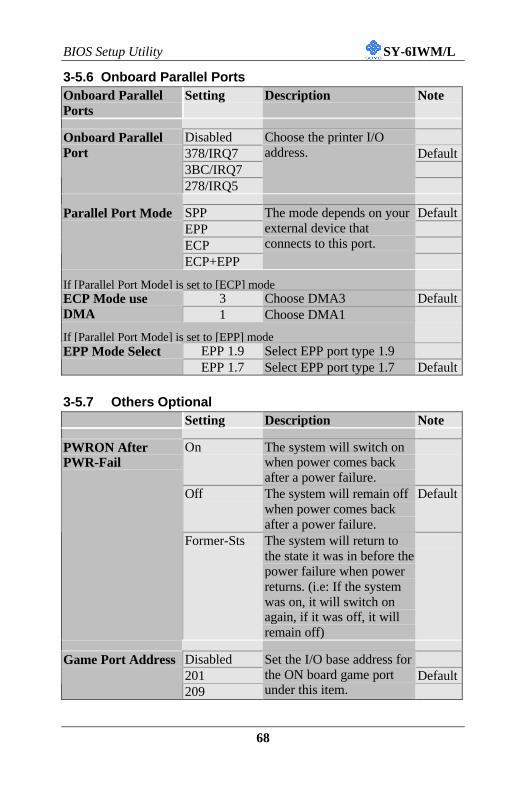
3-5.6 Onboard Parallel PortsOnboard ParallelPorts
Setting Description Note
Disabled378/IRQ7 Default3BC/IRQ7
Onboard ParallelPort
278/IRQ5
Choose the printer I/Oaddress.
SPP DefaultEPPECP
Parallel Port Mode
ECP+EPP
The mode depends on yourexternal device thatconnects to this port.
If [Parallel Port Mode] is set to [ECP] mode3 Choose DMA3 DefaultECP Mode use
DMA 1 Choose DMA1
If [Parallel Port Mode] is set to [EPP] modeEPP 1.9 Select EPP port type 1.9EPP Mode SelectEPP 1.7 Select EPP port type 1.7 Default
3-5.7 Others OptionalSetting Description Note
On The system will switch onwhen power comes backafter a power failure.
Off The system will remain offwhen power comes backafter a power failure.
Default
PWRON AfterPWR-Fail
Former-Sts The system will return tothe state it was in before thepower failure when powerreturns. (i.e: If the systemwas on, it will switch onagain, if it was off, it willremain off)
Disabled201 Default
Game Port Address
209
Set the I/O base address forthe ON board game portunder this item.
BIOS Setup Utility SY-6IWM/L
69
Others OptionalSetting Description Note
Disabled Default330
Midi Port Address
300
Set the I/O address for theon board Midi port here.
If [Midi Port Address] is set to [330]/[300] mode5Midi Port IRQ10
Select the IRQ that theMidi port uses under thisthem.
Default
3-6 POWER MANAGEMENT SETUPThe [POWER MANAGEMENT SETUP] sets the system's power saving
functions.
CMOS Setup Utility – Copyright ( C ) 1984-1999 Award SoftwarePower Management Setup
ACPI Function EnabledxACPI Suspend Type S1 (POS)
Item Help
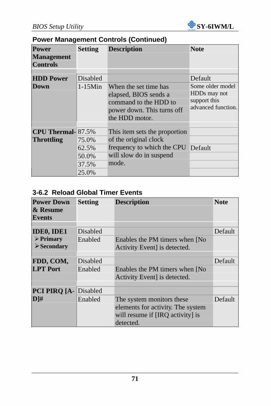
Power Management User DefineVideo Off Method DPMSVideo Off In Suspend YesSuspend Type Stop GrantMODEM Use IRQ 3Suspend Mode DisabledHDD Power Down DisabledCpu Thermal-Throttling 62.5%
** Reload Global Timer Events **Primary IDE 0 DisabledPrimary IDE 1 DisabledSecondary IDE 0 DisabledSecondary IDE1 DisabledFDD,COM, LPT Port DisabledPCI PIRQ[A-D]# Disabled
Menu Level 4
áâàß:Move Enter:Select +/-/PU/PD:Value F10:Save ESC:Exit F1:General Help
Legacy ISA Choose IRQ-# andDMA-# assigned toLegacy ISA card.
IRQ-3,4,5,7,9,10,11,12,14,15
DMA-0,1,3,5,6,7Under this item the user can assign an IRQ to a PCI slot. However, there undersome conditions the IRQ will not be assigned as selected under this item:1. IRQs 0, 1, 2, 6, 8, 13 can NOT be assigned, because they are fixed.2. IRQs 5, 9, 10, 11 are available3. IRQs 3,4,7,12,14 and 15 will only be assigned if they are free. See the table
How to set the BIOS to release the IRQ to the PnP Interrupt pool:InterruptLine PnP / PCI configuration Integrated PeripheralsIRQ 15 IRQ 15: PCI / ISA PnP On-Chip Secondary PCI IDE: disabledIRQ 14 IRQ 14: PCI / ISA PnP On-Chip Primary PCI IDE: disabled
IRQ 12 IRQ 12: PCI / ISA PnPInterrupt 12 will be released by the PnPBIOS automatically if the PS/2 Mouse Portis not used.
IRQ 7 IRQ 7: PCI / ISA PnP Onboard parallel port: disabledIRQ 4 IRQ 4: PCI / ISA PnP Onboard Serial port 1: disabledIRQ 3 IRQ 3: PCI / ISA PnP Onboard Serial port 2: disabled4. Your OS may reassign another interrupt to a PCI slot after BIOS passes control
to the OS, especially if you use Windows 95, 98 or NT.
Disabled BIOS will assgin IRQ forUSB port.
Assign IRQFor USB
Enabled BIOS won’t assign IRQ forUSB port.
Default
5. Your OS may reassign another interrupt to a PCI slot after BIOS passes controlto the OS, especially if you use Windows 95, 98 or NT.
Auto DefaultSlot 1/2/3 UseIRQ NO.
Set to Auto the BIOS willusing IRQs Automatically.
3-7.2 MULTI I/O ADDRESSES
Default settings for multi-I/O addresses are as follows:
Port I/O Address IRQ Status
LPT1 378H 7 ECP/EPP
COM1 3F8H 4
COM2 2F8H 3
Warning: If a default I/O address conflicts with other I/O cards
such as sound card, you must change one of the I/O addresses to
remedy to this address conflict. (I/O addresses can be adjusted from
the BIOS Setup Utility)
BIOS Setup Utility SY-6IWM/L
75
3-8 PC HEALTH STATUSThis option sets the Motherboard's PC Health Status.
CMOS Setup Utility – Copyright ( C ) 1984-1999 Award SoftwarePC Health Status
CPU Warning Temperature DisabledCurrent System Temp. 25 º C / 77 º F
Item Help
Current CPU Dio Temperature 40 º C / 104 º FCurrent CPUFAN Speed 5192 RPM
Set CPU temperature from 50°Cto 70°C. The CPU will slowdown when CPU temperaturegoes beyond the preset value.The CPU will continue to runslow until the temperaturereturns back within the saferange.
Current SystemTemp. °C/°F
Show the current status of thesystem temperature.
Current CPUDioTemperature
°C/°FShow the current status of CPUtemperature.
CurrentCPUFAN Speed °C/°F
Show the current status of CPUFan
Vcore, VTT,3.3V, +5V,+12V, VBAT,5VSB
V
Show the current voltage status.
BIOS Setup Utility SY-6IWM/L
77
3-9 LOAD OPTIMIZED DEFAULTSSelect the [Load Optimized Defaults] option from the Main Menu to load
the system values you have previously saved. This option is recommended
if you need to reset the system setup and to retrieve the old values.
CMOS Setup Utility – Copyright ( C ) 1984-1999 Award Software
4Soyo Combo Feature 4PC Health Status
4Standard CMOS Features Load Optimized Defaults
4Advanced BIOS Features Load Fail - Safe Defaults
4Advanced Chipset Features Set Supervisor Password
Type [Y] to use the Setup Defaults followed by [Enter] or otherwise [N] to
return to the Main Menu and keep current values.
Warning: If you run into any problem after changing the BIOS
configuration, please load the SETUP DEFAULTS for stable
performance.
Load Fail - Safe Defaults (Y/N)? Y
BIOS Setup Utility SY-6IWM/L
79
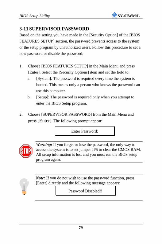
3-11 SUPERVISOR PASSWORDBased on the setting you have made in the [Security Option] of the [BIOS
FEATURES SETUP] section, the password prevents access to the system
or the setup program by unauthorized users. Follow this procedure to set a
new password or disable the password:
1. Choose [BIOS FEATURES SETUP] in the Main Menu and press
[Enter]. Select the [Security Options] item and set the field to:
a. [System]: The password is required every time the system is
booted. This means only a person who knows the password can
use this computer.
b. [Setup]: The password is required only when you attempt to
enter the BIOS Setup program.
2. Choose [SUPERVISOR PASSWORD] from the Main Menu and
press [Enter]. The following prompt appear:
Warning: If you forget or lose the password, the only way toaccess the system is to set jumper JP5 to clear the CMOS RAM.All setup information is lost and you must run the BIOS setupprogram again.
Note: If you do not wish to use the password function, press[Enter] directly and the following message appears:
Enter Password:
Password Disabled!!
BIOS Setup Utility SY-6IWM/L
80
3. Enter your new password and press [Enter]. The following message
appears, prompting to confirm the new password:
4. Re-enter your password and then press [Enter] to exit to the MainMenu.
This diagram outlines the password selection procedure:
3-12 USER PASSWORDWhen the user password option is on, you are not allowed to change any
setting in the [CMOS SETUP UTILITY] except for changing the user's
password.
The password setting procedure is similar to that for the [SUPERVISOR
PASSWORD] (Refer to section 3-9).
ROM PCI/ISA BIOS
CMOS SETUP UTILITY
AWARD SOFTWARE, INC.
STANDARD CMOS SETUP
BIOS FEATURES SETUP
CHIPSET FEATURES SETUP
POWER MANAGEMENT SETUP
PNP/PCI CONFIGURATION
LOAD SETUP DEFAULTS
LOAD BIOS DEFAULTS
INTEGRATED PERIPHERALS
SUPERVISOR PASSWORD
USER PASSWORD
IDE HDD AUTO DETECTION
SAVE & EXIT SETUP
EXIT WITHOUT SAVING
Esc
F10
: Quit
: Save & Exit Setup
↑ ↓ → ←
(Shift) F2
: Select Item
: Change Color
Time, Date, Hard Disk Type…
Enter Password:
Enter Password: ∗ ∗ ∗ ∗ ∗ Password Disabled!!
Confirm Password: ∗ ∗ ∗ ∗ ∗
Press: ↔Without entering password
Type the Password
Press: ↔
After you confirm the
password, press ° to exit
Type the Passwordand Press: <Enter>
Press <Enter> withoutentering the password
After you confirm the password,press <Esc> to exit
Confirm Password:
BIOS Setup Utility SY-6IWM/L
81
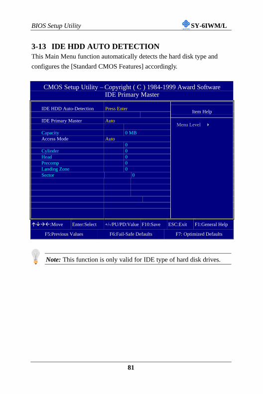
3-13 IDE HDD AUTO DETECTIONThis Main Menu function automatically detects the hard disk type and
configures the [Standard CMOS Features] accordingly.
CMOS Setup Utility – Copyright ( C ) 1984-1999 Award SoftwareIDE Primary Master
IDE HDD Auto-Detection Press EnterItem Help
IDE Primary Master Auto
Capacity 0 MBAccess Mode Auto
0Cylinder 0Head 0Precomp 0Landing Zone 0Sector 0
Menu Level 4
áâàß:Move Enter:Select +/-/PU/PD:Value F10:Save ESC:Exit F1:General Help
Note: This function is only valid for IDE type of hard disk drives.
Drivers installation SY-6IWM/L
82
Chapter 4
THE SOYO CD
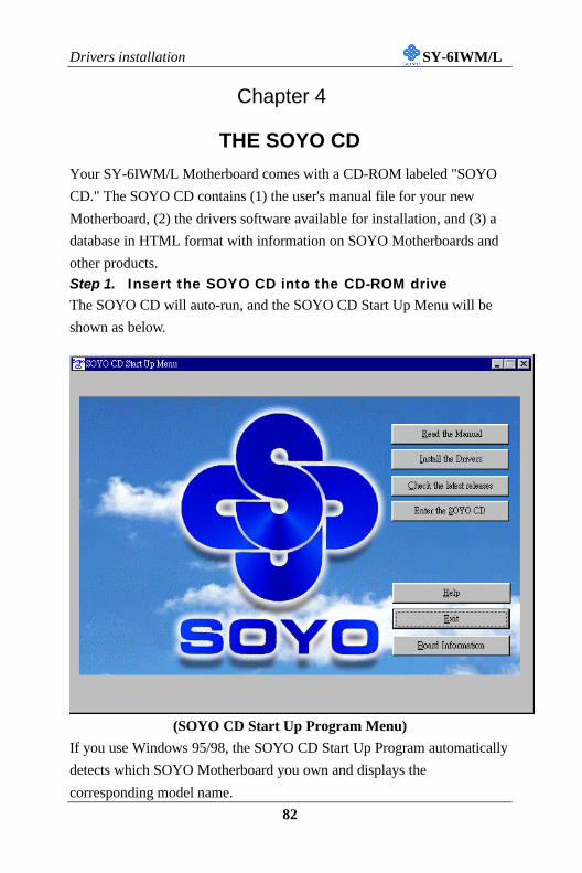
Your SY-6IWM/L Motherboard comes with a CD-ROM labeled "SOYO
CD." The SOYO CD contains (1) the user's manual file for your new
Motherboard, (2) the drivers software available for installation, and (3) a
database in HTML format with information on SOYO Motherboards and
other products.
Step 1. Insert the SOYO CD into the CD-ROM driveThe SOYO CD will auto-run, and the SOYO CD Start Up Menu will be
shown as below.
(SOYO CD Start Up Program Menu)
If you use Windows 95/98, the SOYO CD Start Up Program automatically
detects which SOYO Motherboard you own and displays the
corresponding model name.
Drivers installation SY-6IWM/L
83
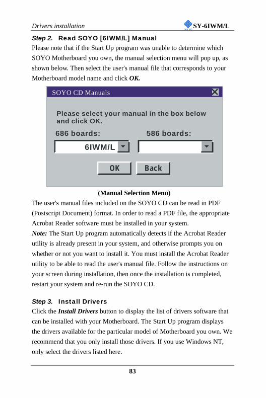
Step 2. Read SOYO [6IWM/L] ManualPlease note that if the Start Up program was unable to determine which
SOYO Motherboard you own, the manual selection menu will pop up, as
shown below. Then select the user's manual file that corresponds to your
Motherboard model name and click OK.
(Manual Selection Menu)
The user's manual files included on the SOYO CD can be read in PDF
(Postscript Document) format. In order to read a PDF file, the appropriate
Acrobat Reader software must be installed in your system.
Note: The Start Up program automatically detects if the Acrobat Reader
utility is already present in your system, and otherwise prompts you on
whether or not you want to install it. You must install the Acrobat Reader
utility to be able to read the user's manual file. Follow the instructions on
your screen during installation, then once the installation is completed,
restart your system and re-run the SOYO CD.
Step 3. Install DriversClick the Install Drivers button to display the list of drivers software that
can be installed with your Motherboard. The Start Up program displays
the drivers available for the particular model of Motherboard you own. We
recommend that you only install those drivers. If you use Windows NT,
only select the drivers listed here.
SOYO CD Manuals
Please select your manual in the box belowand click OK.
686 boards: 586 boards:
OK Back
6IWM/L
Drivers installation SY-6IWM/L
84
However, to display the list of all drivers software available with SOYO
Motherboards, click the Display all drivers on the SOYO CD button.
Please make sure to install only the drivers adapted to your system, or
otherwise this cause system malfunctions.
(Driver Installation Menu)
A short description of all available drivers follows:
Ø INTEL Whitney VGA Drivers for Win9x
In order to be able to make use of the integrated VGA function in
your Whitney chipset, you will need to install this driver first. For
Windows 95/98 only.
Ø INTEL Whitney .inf utility for Win 9x
Windows 95 and 98 will not recognize the new INTEL Whitney
chipset properly. To update the necessary .inf files that will help
Windows recognize the Whitney chipset, please run this utility.
Ø INTEL Whitney security utility for Win 9x/NT
Please select the driver you want to install and click OK, You will have to restart your system after installation. Only the drivers that are relevant to your board are displayed initially.
Intel Whitney VGA Drivers for Win 9xIntel .inf utility for Win 9xIntel Whitney security utility for Win 9x/NTWhitney Winbond Hardware Doctor for Win 95/98
Cancel Display all drivers on the SOYO CD OK
Driver Installation
Drivers installation SY-6IWM/L
85
This utility makes use of the random number generator in the FWH
of your 810/820 chipset. for Win 95/98/NT.
Ø Whitney Winbond hardware Doctor for Win 95/98
Your motherboard comes with a hardware monitoring IC. By installing
this utility Temperature, Fan speed and Voltages can be monitored. It is
also possible to set alarms when current system values exceed or fall
below pre-set values.
Select which driver you want to install and click OK, or click Cancel to
abort the driver installation and return to the main menu.
Note: Once you have selected a driver, the system will automatically exit
the SOYO CD to begin the driver installation program. When the
installation is complete, most drivers require to restart your system before
they can become active.
Step 5. Check the Latest ReleasesClick the 'Check the latest Releases' button to go the SOYO
Website to automatically find the latest BIOS, manual and driver
releases for your motherboard. This button will only work if
your computer is connected to the internet through a network or
modem connection. Make sure to get your modem connection up
before clicking this button.
Step 6. Enter the SOYO CDClick the Enter SOYO CD button to enter the SOYO HTML database.
The Start Up program will activate the default HTML browser installed on
your system (for example, Internet Explorer or Netscape) to visualize the
contents of the SOYO CD.
The SOYO CD contains useful information about your Motherboard and
other SOYO products available. For your convenience, this information is
available in HTML format, similar to the format widely used on the
Internet.
Drivers installation SY-6IWM/L
86
Note: If no HTML browser is installed on your system, the Start Up
program will prompt you on whether or not you would like to install the
Internet Explorer* browser. Click YES to install the HTML browser. After
the installation is complete, please restart your system. Then re-run the
SOYO CD and you will be able to browse the SOYO HTML database.
(* Internet Explorer is a Microsoft Trademark)
Sigmatel Audio Drivers installation SY-6IWM/L
87
Chapter 5
SIGMATEL AUDIO DRIVER INSTALLATION
Installing the Sigmatel Audio Drivers under windows98/ Windows Second Edition1. Open Device Manager.
2. PCI Multimedia Device will have a yellow marker the first time the
operating system is installed.
3. Select "Properties" on the yellow marker.
4. Select the "Driver" tab.
5. Click on "Update Driver"
6. Select the following directory:
D:\driv-all\sigmatel\win98se
and click OK. You will need the Windows 98 or Windows 98 Second
Edition to complete the WDM installation.
7. After informing windows of the driver directory the driver will be
installed. Restart your system after installation.
Uninstalling/Re-Installing Sigmatel Audio Drivers1. Open Device Manager.
2. Remove the Sigmatel Audio Codec entry in the Sound, Video, and
Game Controllers section. Do not change the game controller in this
audio solution.
3. Delete the sigmatel INF file in c:\windows\inf\other
4. Restart your PC for Plug and Play to reinitialize your system.
Sigmatel Audio Drivers installation SY-6IWM/L
88
Installing the Sigmatel Audio Drivers for WindowsNT1. Double click the MULTIMEDIA icon in the control panel. The
Multimedia Properties windows will appear. Click on the Devices tab
and press the Add button.
2. Select "Unlisted or Updated Drivers" from the list of drivers in the Add
window by placing the mouse pointer over it and clicking the left
mouse button. Press the OK button.
3. The Install Driver dialog box will appear and request the path of the
location of the drivers to be installed. Enter D:\driv-
all\sigmatel\WinNT40 (where D: is your CDROM drive) If the
installation fails, first copy all the files in the above directory to your
harddisk and give that directory to NT.
4. Windows NT will display a dialog box asking you to restart your
system.
Press the Restart Now button to complete the installation.
Uninstalling or Updating the Sigmatel Audio Drivers1. Double click on the MULTIMEDIA icon in the control panel. Select
the Devices tab from the Multimedia properties window.
2. Double click on the Audio Devices entry from the Multimedia devices
list. Select the driver by placing the mouse pointer over the sigmatel
driver label and clicking the left mouse button.
3. Press the REMOVE button.
4. A question box will appear to verify your decision. Press the YES
button.
5. Windows NT will display a dialog box asking you to restart your
system. Press the Restart Now button to complete the Un-installation.
Sigmatel Audio Drivers installation SY-6IWM/L
89
SynthCore Lite Application for Windows NT 4.0The CD contains a SynthCore Lite application program, that the Quick
Settings Guide does not describe. It can be installed by running win-
wave.exe in the D:\drive-all\sigmatel\win-wave directory. (Were D is your
CD-ROM drive letter).
Note that the NT4 installation requires a manual step at the end of the
installation. This step apllies to NT4 only. (NT4 Service Pack 4 has to be
installed, Service Pack 4 includes DirectSound 3)
1) After you run the normal installer, DO NOT reboot your system yet.
2) Go to Start > Settings > Control Panel > Multi Media
3) Select the "Devices" tab
4) Select the "Add" Button
5) Select "Unlisted or Undated Driver"
6) Browse to c:\Program Files\Staccato\SynthCore Lite\oemsetup.inf and
select this file.
7) Now look under the MIDI Devices tab, you should see the Staccato