SV1800-C, SV1800B-C, SV1800-F, SV1800B-F, SV2800, and SV2800B Security Policy
4
2016 Symantec Corporation This document may be freely reproduced & distributed whole & intact including this copyright
notice.
5
1. Introduction
1.1 Purpose
This document is a non-proprietary Cryptographic Module Security Policy for the SSL Visibility Appliance models SV1800-C, SV1800B-C, SV1800-F, SV1800B-F, SV2800, and SV2800B. The non-B models can operate with the 3.8.2F, 3.8.4FC, or 3.10 firmware version. The B-models require the 3.10 firmware version to operate. This policy was prepared as part of the Level 2 FIPS 140-2 validation of the module, and may freely be reproduced and distributed in its entirety (without modification).
Federal Information Processing Standards (FIPS) 140-2, Security Requirements for Cryptographic Modules, specifies the U.S. and Canadian Governments’ requirements for cryptographic modules. The following pages describe how the SSL Visibility Appliance meets these requirements and how to operate the device in a mode compliant with FIPS 140-2.
More information about the FIPS 140-2 standard and validation program is available on the National Institute of Standards and Technology (NIST) Cryptographic Module Validation Program (CMVP) website at: http:// csrc.nist.gov/groups/STM/cmvp/index.html.
In this document, the SSL Visibility Appliance models SV1800-C, SV1800B-C, SV1800-F, SV1800B-F, SV2800, and SV2800B are referred to as the hardware modules, the cryptographic modules, or the modules.
1.2 References
This document only deals with the operation and capabilities of the SV1800-C, SV1800B-C, SV1800-F, SV1800B-F, SV2800, and SV2800B within the technical terms of a FIPS 140-2 cryptographic module security policy. More information on the SV1800-C, SV1800B-C, SV1800-F, SV1800B-F, SV2800, and SV2800B is available from the following sources:
• The Symantec website, www.symantec.com, contains information on the full line of products from Blue Coat.
• The Symantec customer website, https://bto.bluecoat.com, contains product documentation, software downloads, and other information on the full line of products from Symantec.
The CMVP website http://csrc.nist.gov/groups/STM/cmvp/index.html contains contact information for answers to technical or sales-related questions for the module.
1.3 Document Organization
This Security Policy is one document in the FIPS 140-2 Submission Package. In addition to this document, the Submission Package contains:
• Vendor Evidence
• Finite State Machine
• Other supporting documentation as additional references
2016 Symantec Corporation This document may be freely reproduced & distributed whole & intact including this copyright
notice.
6
SV1800-C, SV1800B-C, SV1800-F, SV1800B-F, SV2800, and SV2800B Security Policy
With the exception of this non-proprietary Security Policy, the FIPS 140-2 Submission Package is proprietary to Symantec Corporation, and is releasable only under appropriate non-disclosure agreements. For access to these documents, please contact Symantec Corporation.
2016 Symantec Corporation This document may be freely reproduced & distributed whole & intact including this copyright
notice.
7
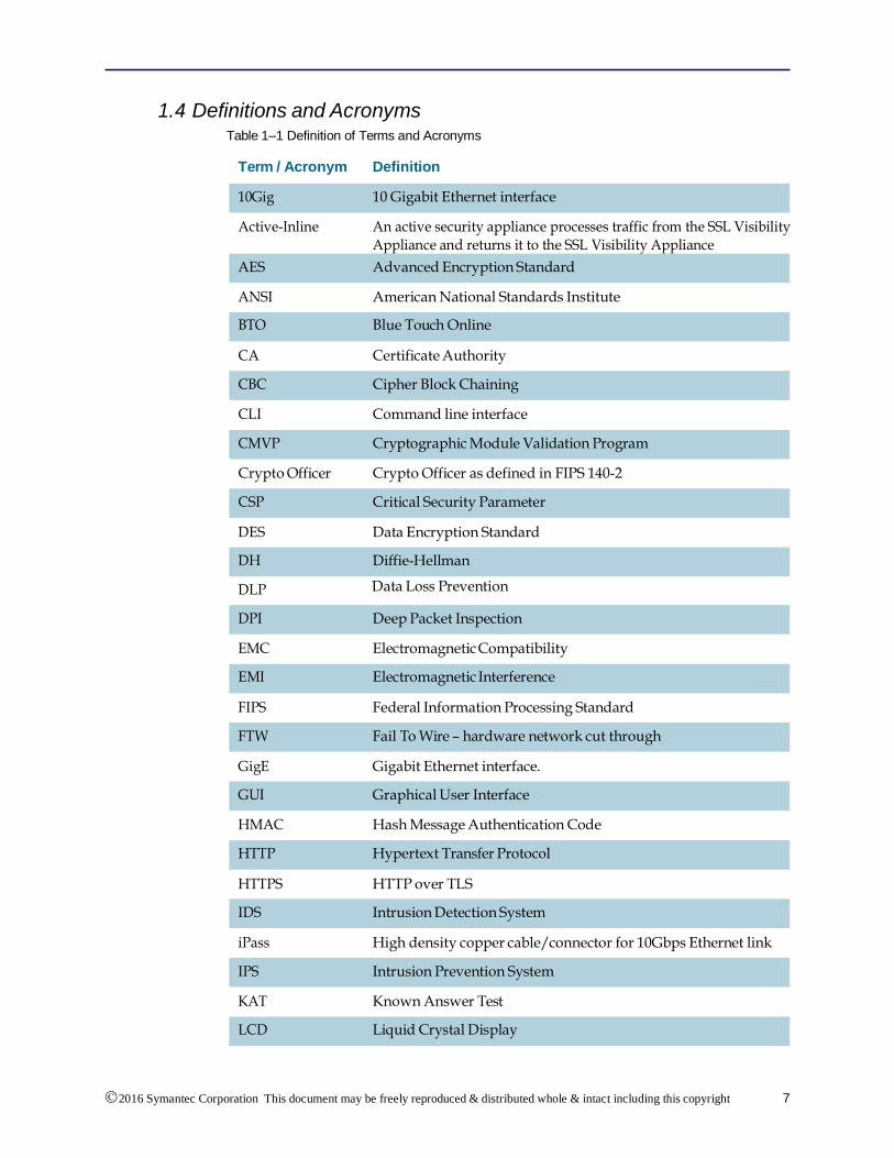
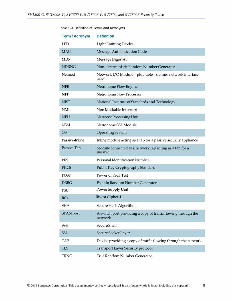
1.4 Definitions and Acronyms Table 1–1 Definition of Terms and Acronyms
Term / Acronym Definition
Active-Inline An active security appliance processes traffic from the SSL Visibility Appliance and returns it to the SSL Visibility Appliance
ANSI American National Standards Institute
CA Certificate Authority
CLI Command line interface
Crypto Officer Crypto Officer as defined in FIPS 140-2
DES Data Encryption Standard
DLP Data Loss Prevention
EMC Electromagnetic Compatibility
FIPS Federal Information Processing Standard
GigE Gigabit Ethernet interface.
HMAC Hash Message Authentication Code
HTTPS HTTP over TLS
iPass High density copper cable/connector for 10Gbps Ethernet link
KAT Known Answer Test
10Gig 10 Gigabit Ethernet interface
AES Advanced Encryption Standard
BTO Blue Touch Online
CBC Cipher Block Chaining
CMVP Cryptographic Module Validation Program
CSP Critical Security Parameter
DH Diffie-Hellman
DPI Deep Packet Inspection
EMI Electromagnetic Interference
FTW Fail To Wire – hardware network cut through
GUI Graphical User Interface
HTTP Hypertext Transfer Protocol
IDS Intrusion Detection System
IPS Intrusion Prevention System
LCD Liquid Crystal Display
2016 Symantec Corporation This document may be freely reproduced & distributed whole & intact including this copyright
notice.
8
SV1800-C, SV1800B-C, SV1800-F, SV1800B-F, SV2800, and SV2800B Security Policy
Passive-Inline Inline module acting as a tap for a passive security appliance
PIN Personal Identification Number
POST Power On Self Test
PSU Power Supply Unit
SHA Secure Hash Algorithm
SSH Secure Shell
TAP Device providing a copy of traffic flowing through the network
TRNG True Random Number Generator
MAC Message Authentication Code
NDRNG Non-deterministic Random Number Generator
NFE Netronome Flow Engine
NIST National Institute of Standards and Technology
NPU Network Processing Unit
OS Operating System
Module connected to a network tap acting as a tap for a passive security appliance
PKCS Public Key Cryptography Standard
DRBG Pseudo Random Number Generator
Rivest Cipher 4
SPAN port A switch port providing a copy of traffic flowing through the network
SSL Secure Socket Layer
TLS Transport Layer Security protocol
2016 Symantec Corporation This document may be freely reproduced & distributed whole & intact including this copyright
notice.
9
2. SV1800-C, SV1800B-C, SV1800-F, SV1800B-F, SV2800, and SV2800B
2.1 Overview
SSL Visibility Appliance products provide two main functions when deployed within a network:
• They enable other security appliances to see a non encrypted version of SSL/TLS traffic that is crossing the network. This is called SSL Inspection.
• They can act as a policy control point enabling explicit control over what SSL/TLS traffic is and is not allowed across the network.
The SSL Visibility Appliance is designed to work alongside existing security devices such as Intrusion Prevention Systems (IPS), Intrusion Detection Systems (IDS), Data Loss Prevention systems (DLP), Network Forensic appliance and others. It provides a non-encrypted version of SSL/TLS traffic to the associated appliances while maintaining an end-to-end SSL/TLS connection between the client and server involved in the session.
There are three basic connectivity modes that define how the SSL Visibility Appliance and the associated security appliance are connected to each other and to the network. These modes are identified as:
• Active-Inline
• Passive-Inline
• Passive-Tap
The Active/Passive designation refers to the associated security appliance and how it behaves while the Inline/Tap designation refers to how the SSL Visibility Appliance is connected to the network. An “Active” associated appliance processes traffic from the SSL Visibility Appliance and then returns the traffic to the SSL Visibility Appliance, while a “Passive” appliance simply consumes traffic from the SSL Visibility Appliance.
The SSL Visibility Appliance can be either “Inline,” or a TAP, which is connected to a network span or tap port. The following figures show these three modes of operation.
2016 Symantec Corporation This document may be freely reproduced & distributed whole & intact including this copyright
notice.
10
SV1800-C, SV1800B-C, SV1800-F, SV1800B-F, SV2800, and SV2800B Security Policy
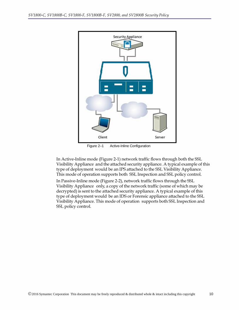
Figure 2–1 Active-Inline Configuration
In Active-Inline mode (Figure 2-1) network traffic flows through both the SSL Visibility Appliance and the attached security appliance. A typical example of this type of deployment would be an IPS attached to the SSL Visibility Appliance. This mode of operation supports both SSL Inspection and SSL policy control.
In Passive-Inline mode (Figure 2-2), network traffic flows through the SSL Visibility Appliance only, a copy of the network traffic (some of which may be decrypted) is sent to the attached security appliance. A typical example of this type of deployment would be an IDS or Forensic appliance attached to the SSL Visibility Appliance. This mode of operation supports both SSL Inspection and SSL policy control.
2016 Symantec Corporation This document may be freely reproduced & distributed whole & intact including this copyright
notice.
11
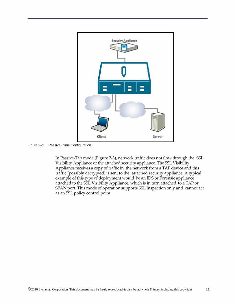
Figure 2–2 Passive-Inline Configuration
In Passive-Tap mode (Figure 2-3), network traffic does not flow through the SSL Visibility Appliance or the attached security appliance. The SSL Visibility Appliance receives a copy of traffic in the network from a TAP device and this traffic (possibly decrypted) is sent to the attached security appliance. A typical example of this type of deployment would be an IDS or Forensic appliance attached to the SSL Visibility Appliance, which is in turn attached to a TAP or SPAN port. This mode of operation supports SSL Inspection only and cannot act as an SSL policy control point.
SV1800-C, SV1800B-C, SV1800-F, SV1800B-F, SV2800, and SV2800B Security Policy
2016 Symantec Corporation This document may be freely reproduced & distributed whole & intact including this copyright
notice.
12
Figure 2–3 Passive-Tap Configuration
By allowing the attached security appliance to view a decrypted version of SSL/ TLS traffic, the SSL Visibility Appliance enables the security appliance to detect/ block threats that are hidden within encrypted SSL/TLS flows. As the percentage of SSL/TLS traffic in networks is growing significantly with increasing use of Web 2.1 applications and Cloud based applications, it is increasingly important that network security appliances can do their job even when the traffic is sent over SSL/TLS connections.
Detecting, intercepting, decrypting and re-encrypting SSL/TLS traffic is a complex and computationally intense activity. Providing SSL/TLS inspection capabilities in a device that can be placed in-line in either a Gigabit Ethernet or 10 Gigabit Ethernet network link and which will not cause a performance bottleneck requires hardware acceleration. In the case of the SSL Visibility Appliance this acceleration is provided by a Netronome Network Flow Engine (NFE) card that contains one of Netronome’s NFP-3240 flow processor chips. The NFP-3240 contains 40 cores optimized for processing network traffic and provides significant acceleration and offloads for the standard CPUs used on the SV1800-C, SV1800B-C, SV1800-F, SV1800B-F, SV2800, and SV2800B motherboards.
The SSL Visibility Appliance software provides the ability to inspect both incoming and outgoing SSL/TLS traffic and detects SSL/TLS traffic by deep packet inspection (DPI) so no matter what port the SSL/TLS traffic is using it will be detected. Once an SSL/ TLS flow has been detected the SSL Visibility Appliance policy engine determines what to do with the flow:
• it can be inspected providing a decrypted version to the attached appliance(s)
2016 Symantec Corporation This document may be freely reproduced & distributed whole & intact including this copyright
notice.
13
• it can be cut through, allowing the attached appliance(s) to see the original encrypted flow
• it can be blocked such that the flow is terminated and cannot continue.
The policy engine allows policy to be based on a wide range of parameters such as:
• the source/destination IP address of the flow
• the Distinguished Name (DN) of the subject or issuer contained in the SSL/TLS server certificate sent by the server
• the cipher suite being used for the flow
This allows for fine grained control over which SSL/TLS traffic is inspected, and, when the SSL Visibility Appliance is deployed in-line, enables fine grained policy control over what SSL/TLS traffic is allowed in the network.
All SSL/TLS traffic seen by the SSL Visibility Appliance, whether it is using approved or non- approved algorithms will be processed to a degree. At a minimum the SSL/TLS handshake will be observed in order to collect information that the policy engine will use to determine how the flow should be handled. Using the policy rules it is possible to cause the following actions to be applied to a flow:
• block the SSL/TLS flow
• allow the SSL/TLS flow without any inspection
• allow the SSL/TLS flow with the flow being inspected
The policy engine is aware of the cipher suite that the SSL/TLS flow is using, and can base its decision on that. So, it is possible to configure policy settings that will prevent any SSL/TLS flows using non-approved algorithms from being established through the SSL Visibility Appliance if that is desired. If SSL/TLS flows using non-approved algorithms are allowed by the policy engine then they should be considered as being “clear text” due to the use of non-approved algorithms.
2.2 Module Specification
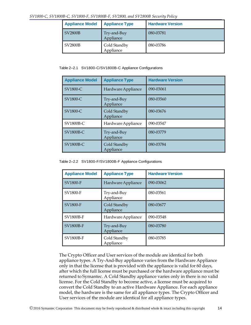
The hardware version numbers in the tables below provides a mapping between the hardware versions and the appliance types available. All appliance types, for a given model, have the exact same hardware and firmware, and are exactly the same from a cryptographic functionality and boundary perspective.
Table 2–2 SV2800/2800B Appliance Configurations
Appliance Model Appliance Type Hardware Version
SV2800 Hardware Appliance 090-03063
SV2800 Try-and-Buy Appliance
080-03562
SV2800 Cold Standby Appliance
080-03678
SV2800B Hardware Appliance 090-03549
SV1800-C, SV1800B-C, SV1800-F, SV1800B-F, SV2800, and SV2800B Security Policy
2016 Symantec Corporation This document may be freely reproduced & distributed whole & intact including this copyright
The Crypto Officer and User services of the module are identical for both appliance types. A Try-And-Buy appliance varies from the Hardware Appliance only in that the license that is provided with the appliance is valid for 60 days, after which the full license must be purchased or the hardware appliance must be returned to Symantec. A Cold Standby appliance varies only in there is no valid license. For the Cold Standby to become active, a license must be acquired to convert the Cold Standby to an active Hardware Appliance. For each appliance model, the hardware is the same for all appliance types. The Crypto Officer and User services of the module are identical for all appliance types.
2016 Symantec Corporation This document may be freely reproduced & distributed whole & intact including this copyright
notice.
15
The SV1800-C, SV1800B-C, SV1800-F, SV1800B-F, SV2800, and SV2800B are high performance transparent SSL/TLS proxies that can be deployed in Gigabit Ethernet networks, and the SV2800 and SV2800B can also be deployed in 10G Ethernet networks. The SV1800-C, SV1800B-C, SV1800-F, SV1800B-F, SV2800, and SV2800B are 1U high rack mountable devices.
The SV2800/SV2800B have three front facing modular I/O bays that allow for flexibility in the number of network interfaces and in the type of media supported. Network I/O Modules (Netmods) are installed in the three bays to configure the desired combination of interfaces.
All of the Netmod interfaces and the switching module that plug into the front of the SV2800/SV2800B connect to the network segments on which traffic is being monitored/inspected. These ports are only used to access the network data that is being processed by the SV2800/SV2800B; they are not associated with any cryptographic processes, keys, critical security parameters (CSP) or any FIPS relevant data. These ports do not allow access to the management services of the SV2800/SV2800B and cannot be used to input or output cryptographic keys, CSPs or any FIPS relevant data. The Netmods and associated switch are therefore deemed to be outside the logical cryptographic boundary.
Figure 2-4.1 shows an SV2800/SV2800B device with three Netmods installed while figure 2-4.2 shows an SV2800/SV2800B device without any Netmods installed. In this example, the Netmods each support 4 x 1Gig copper interfaces. Available Netmod options are listed below, other Netmod types may become available in the future:
• 4 x GigE copper (4 ports of 10/100/1000Base-T with FTW)
• 4 x GigE fiber (4 ports of 1000Base-SX with FTW)
• 2 x 10Gig fiber (2 ports of 10GBase-SR with FTW)
• 2 x 10Gig fiber (2 ports of 10GBase-LR with FTW)
Fail to wire (FTW) hardware allows pairs of network ports to be physically connected to each other in the event that the system is powered off or that a failure is detected. Depending on how the network is connected to the SV2800, this allows network traffic to continue flowing even when the system is powered off or in a failure state. When FTW is active, traffic is passed between ports on a Netmod and never enters the module.
Note: Netmods are NOT hot swappable. The system must be powered off before removal or installation of Netmods.
Figure 2–4.1 SV2800/SV2800B, Front View with Netmods Installed
Figure 2-4.2 shows the SV2800/SV2800B with all Netmods removed.
SV1800-C, SV1800B-C, SV1800-F, SV1800B-F, SV2800, and SV2800B Security Policy
2016 Symantec Corporation This document may be freely reproduced & distributed whole & intact including this copyright
notice.
16
Figure 2–4.2 SV2800/SV2800B Front view with Netmods Removed
Figure 2-5.1 and Figure 2-5.2 shows the front of the SV1800-F/SV1800B-F and SV1800-C/SV1800B-C devices
Figure 2–5.1 SV1800-C/SV1800B-C Front View
Figure 2–5.2 SV1800-F/SV1800B-F Front View
From left to right, the front panel includes an LCD display, keypad, status LEDs, NMI button, reset button, ID button, power button and a USB connector.
Figure 2-6 shows the SV2800/SV2800B front panel display area in detail. Note that this unit has a 4 x GigE fiber Netmod installed in the right hand bay.
Figure 2–6 SV2800 Front Panel Controls and Display
Figure 2-6.1 shows the SV1800-C, SV1800B-C, SV1800-F, and SV1800B-F front panel display area in detail.
Figure 2–6.1 SV1800-C, SV1800B-C, SV1800-F, and SV1800B-F Front Panel Controls and Display
The combination of Netmods installed in an SV2800/SV2800B is not important for
2016 Symantec Corporation This document may be freely reproduced & distributed whole & intact including this copyright
notice.
17
FIPS 140-2 validation as the Netmods are all outside of the logical cryptographic boundary (see "2.3 Module Interfaces" on page 20).
The back of the SV2800 is shown in Figure 2-7 and has the following elements going from left to right:
• Serial port (RJ45 connector)
• VGA display connector
• 2 sets of 2 x USB 2.0 ports
• 2 x GigE ports each with two built in LEDs – port 1 is used for management, port 2 is unused
• 2 x hot swappable power supply bays
Figure 2–7 SV2800 Back Panel
The back of the SV2800B differs slightly (serial port location only) from the SV2800 and is shown in Figure 2-7.1 and has the following elements going from left to right:
• VGA display connector
• 2 x USB 2.0 and 2 x USB 3.0 ports
• 2 x GigE ports each with two built in LEDs – port 1 is used for management, port 2 is unused
• Serial port (RJ45 connector)
• 2 x hot swappable power supply bays
Figure 2–7.1 SV2800B Back Panel
The back of the SV1800-C, SV1800B-C, SV1800-F and SV1800B-F is shown in Figure 2-7.2 and has the following elements going from left to right:
• 2 x GigE ports each with two built in LEDs – port 1 is used for management, port 2 is unused
• 1 sets of 2 x USB 2.0 ports
• VGA display connector
• Serial port
• 2 x hot swappable power supply bays
SV1800-C, SV1800B-C, SV1800-F, SV1800B-F, SV2800, and SV2800B Security Policy
2016 Symantec Corporation This document may be freely reproduced & distributed whole & intact including this copyright
notice.
18
Figure 2–7.2 SV1800-C, SV1800B-C, SV1800-F and SV1800B-F Back Panel
Covers on the upper surface of the SV1800-C, SV1800B-C, SV1800-F, SV1800B-F, SV2800, and SV2800B can be removed to gain access to the interior of the unit. These covers should not be removed by end users, and may require removal by trained field engineers when maintaining a system. These covers need to be sealed with tamper evident labels when operating in FIPS 140-2 mode. Figures 2-8, 2-8.1, and 2-8.2
Figure 2–8 SV2800 and SV2800B Front/Top, Top Cover Placed
Figure 2–8.1 SV1800-C and SV1800B-C Front/Top, Top Cover Placed
Figure 2–8.2 SV1800-F and SV1800B-F Front/Top, Top Cover Placed
Section "3.2 Tamper Evident Label Management and Application Instructions" provides guidance on how and where tamper evident labels need to be applied to the SV1800-C, SV1800B-C, SV1800-F, SV1800B-F, SV2800, and SV2800B.
2016 Symantec Corporation This document may be freely reproduced & distributed whole & intact including this copyright
notice.
19
For FIPS 140-2 Level 2 validation the SV2800 was tested with the following configuration:
• SV2800 chassis with 1 x NFE acceleration card installed
• 2 x Intel 5620 quad core CPUs and 24GB of memory
This configuration is Symantec model number SV2800.
For FIPS 140-2 Level 2 validation the SV2800B was tested with the following configuration:
• SV2800B chassis with 1 x NFE acceleration card installed
• 1 x Intel E5-2618L V3 octa-core CPUs and 32GB of memory
This configuration is Symantec model number SV2800B.
For FIPS 140-2 Level 2 validation the SV1800-C and SV1800-F were tested with the following configurations:
• SV1800 chassis with 1 x NFE acceleration card installed
• 1 x Intel 3450 quad core CPU and 16GB of memory
These configurations are Symantec model numbers SV1800-C and SV1800-F.
For FIPS 140-2 Level 2 validation the SV1800B-C and SV1800B-F were tested with the following configurations:
• SV1800B chassis with 1 x NFE acceleration card installed
• 1 x Intel E3 1225 V3 quad core CPU and 16GB of memory
These configurations are Symantec model numbers SV1800B-C and SV1800B-F.
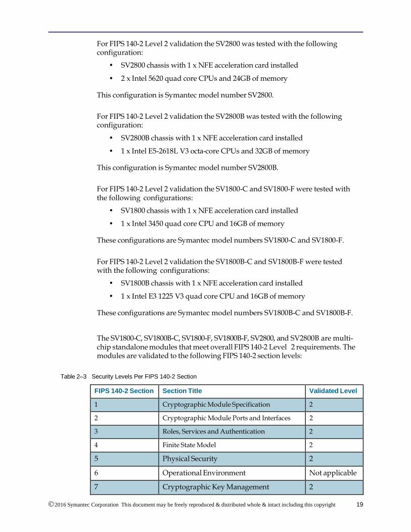
The SV1800-C, SV1800B-C, SV1800-F, SV1800B-F, SV2800, and SV2800B are multi-chip standalone modules that meet overall FIPS 140-2 Level 2 requirements. The modules are validated to the following FIPS 140-2 section levels:
Table 2–3 Security Levels Per FIPS 140-2 Section
FIPS 140-2 Section Section Title Validated Level
1 Cryptographic Module Specification 2
2 Cryptographic Module Ports and Interfaces 2
3 Roles, Services and Authentication 2
4 Finite State Model 2
5 Physical Security 2
6 Operational Environment Not applicable
7 Cryptographic Key Management 2
SV1800-C, SV1800B-C, SV1800-F, SV1800B-F, SV2800, and SV2800B Security Policy
2016 Symantec Corporation This document may be freely reproduced & distributed whole & intact including this copyright
The logical cryptographic boundary of each module is shown in the following pictures and diagrams. All of the Netmod interfaces and the switching module that plug into the front of the SV2800/SV2800B connect to the network segments on which traffic is being monitored/inspected. These ports are only used to access the network data that is being processed by the SV2800/SV2800B; they do not allow access to the management services of the SV2800/SV2800B. The Netmods and associated switch are therefore outside the logical cryptographic boundary. Data input/output to the module from the Netmods and associated switch is via two internal 10Gbps Ethernet connections carried over iPass connectors/cables.
The two pluggable power supply units and the bays that they plug into are not associated with any cryptographic processes, keys, critical security parameters (CSP), or any FIPS relevant data, and are therefore deemed to be outside of the cryptographic boundary.
Note: Netmods are NOT hot-swappable. Power off the system before you remove or install Netmod.
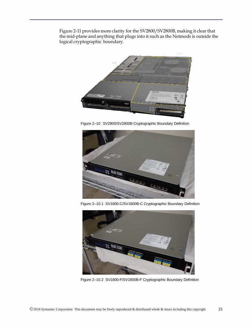
Figure 2-10 shows the SV2800/SV2800B physical cryptographic boundary as a yellow line with the module being everything contained within the yellow boundary line. The physical boundary is defined by the exterior surfaces of the appliance. Figures 2-10.1 and 2-10.2 show the cryptographic boundary for the SV1800-C/SV1800B-C and SV1800-F/SV1800B-F, as the exterior surfaces of the appliances.
2016 Symantec Corporation This document may be freely reproduced & distributed whole & intact including this copyright
notice.
21
Figure 2-11 provides more clarity for the SV2800/SV2800B, making it clear that the mid-plane and anything that plugs into it such as the Netmods is outside the logical cryptographic boundary.
SV1800-C, SV1800B-C, SV1800-F, SV1800B-F, SV2800, and SV2800B Security Policy
2016 Symantec Corporation This document may be freely reproduced & distributed whole & intact including this copyright
notice.
22
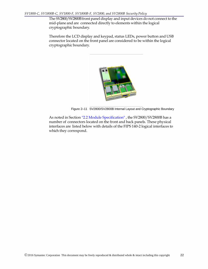
The SV2800/SV2800B front panel display and input devices do not connect to the mid-plane and are connected directly to elements within the logical cryptographic boundary. Therefore the LCD display and keypad, status LEDs, power button and USB connector located on the front panel are considered to be within the logical cryptographic boundary.
Figure 2–11 SV2800/SV2800B Internal Layout and Cryptographic Boundary
As noted in Section "2.2 Module Specification" , the SV2800/SV2800B has a number of connectors located on the front and back panels. These physical interfaces are listed below with details of the FIPS 140-2 logical interfaces to which they correspond.
2016 Symantec Corporation This document may be freely reproduced & distributed whole & intact including this copyright
notice.
23
Table 2–4 SV1800-C, SV1800B-C, SV1800-F, SV1800B-F, SV2800, and SV2800B FIPS 140-2 FIPS Logical Interfaces
FIPS 140-2 logical interface
Port/interface Panel Used in FIPS
mode?
Data input
(SV2800/SV2800B only)
2 iPass connectors each carrying a 10Gbps Ethernet link
Internal Y
Data output
(SV2800/SV2800B only)
2 iPass connectors each carrying a 10Gbps Ethernet link
Internal Y
Data input
(SV1800-C/SV1800B-C only)
8 Ethernet ports Front Y
Data output
(SV1800-C/SV1800B-C only)
8 Ethernet ports Front Y
Data input
(SV1800-F/SV1800B-F only)
8 Fiber ports Front Y
Data output
(SV1800-F/SV1800B-F only)
8 Fiber ports Front Y
Data output USB port Front Y
Data output USB ports Back Y
Control input/Status output
Keypad Front Y
Control input NMI button Front Y
Control input Reset button Front Y
Control input/Status output
ID button Front Y
Control input/Status output
Power button Front Y
Control input/Status output
USB port Front Y
Control input/Status output
Serial port Back Y
Control input/Status output
VGA display connector Back Y
Control input/Status output
USB port Back Y
SV1800-C, SV1800B-C, SV1800-F, SV1800B-F, SV2800, and SV2800B Security Policy
2016 Symantec Corporation This document may be freely reproduced & distributed whole & intact including this copyright
notice.
24
FIPS 140-2 logical interface
Port/interface Panel Used in FIPS
mode?
Status output Status LED for management Ethernet 1
Front Y
Status output LCD display Front Y
Status output Status LED for management
Ethernet 2a
Front Y
Status output Status LED for hard disk activity
Front Y
Status output Status LED for system error Front Y
Control input/Status output
Management Ethernet ports 1
and 2a
Back Y
Status output Ethernet 1 LEDs Back Y
Status output Ethernet 2 LEDsa Back Y
Power input Power connections from removable PSUs
Back Y
a. Ethernet 2 is disabled and cannot be used for management, so these LEDs will never light up.
The front panel status LEDs for Ethernet 1 are green when the link is up and flash amber/yellow to indicate traffic flowing over the link. The two LEDs that are part of the Ethernet ports on the rear panel indicate the operating speed of the link and if data is flowing over the link. The left LED viewed from the back of the unit is green if the link is up and flashes to indicate traffic flow. The right LED can be: off indicating a 10 Mbps connection, green indicating a 100 Mbps connection or amber indicating a GigE connection.
The disk activity LED is green and flashes when there is any disk activity on a SATA port in the system.
The system status LED is green/amber and the various display options indicate different system states. Table 2-5 shows the various system states that can be indicated by the system status LED on the front panel of the unit.
Table 2–5 SV1800-C, SV1800B-F, SV1800-F, SV1800B-F and SV2800, SV2800B System Status Indicator Meaning
Color State System status Meaning
Green Solid OK System ready – no errors detected
Green Blink Degraded Memory, fan, power supply or PCIe failures
Amber Solid Fatal Alarm – system has failed and shut down
Amber Blink Non-Fatal Alarm – system likely to fail – voltage/temp warnings
2016 Symantec Corporation This document may be freely reproduced & distributed whole & intact including this copyright
notice.
25
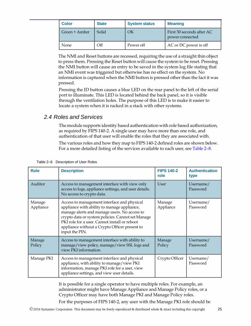
Color State System status Meaning
Green + Amber Solid OK First 30 seconds after AC power connected
None Off Power off AC or DC power is off
The NMI and Reset buttons are recessed, requiring the use of a straight thin object to press them. Pressing the Reset button will cause the system to be reset. Pressing the NMI button will cause an entry to be saved in the system log file stating that an NMI event was triggered but otherwise has no effect on the system. No information is captured when the NMI button is pressed other than the fact it was pressed.
Pressing the ID button causes a blue LED on the rear panel to the left of the serial port to illuminate. This LED is located behind the back panel, so it is visible through the ventilation holes. The purpose of this LED is to make it easier to locate a system when it is racked in a stack with other systems.
2.4 Roles and Services
The module supports identity based authentication with role based authorization, as required by FIPS 140-2. A single user may have more than one role, and authentication of that user will enable the roles that they are associated with.
The various roles and how they map to FIPS 140-2 defined roles are shown below. For a more detailed listing of the services available to each user, see Table 2–8.
Table 2–6 Description of User Roles
Role Description FIPS 140-2 role
Authentication type
Auditor Access to management interface with view only access to logs, appliance settings, and user details. No access to crypto data.
User Username/ Password
Manage Appliance
Access to management interface and physical appliance with ability to manage appliance, manage alerts and manage users. No access to crypto data or system policies. Cannot set Manage PKI role for a user. Cannot install or reboot appliance without a Crypto Officer present to input the PIN.
Manage Appliance
Username/ Password
Manage Policy
Access to management interface with ability to manage/view policy, manage/view SSL logs and view PKI information.
Manage Policy
Username/ Password
Manage PKI Access to management interface and physical appliance, with ability to manage/view PKI information, manage PKI role for a user, view appliance settings, and view user details.
Crypto Officer Username/ Password
It is possible for a single operator to have multiple roles. For example, an administrator might have Manage Appliance and Manage Policy roles, or a Crypto Officer may have both Manage PKI and Manage Policy roles.
For the purposes of FIPS 140-2, any user with the Manage PKI role should be
SV1800-C, SV1800B-C, SV1800-F, SV1800B-F, SV2800, and SV2800B Security Policy
2016 Symantec Corporation This document may be freely reproduced & distributed whole & intact including this copyright
notice.
26
viewed as a Crypto Officer, and any user with the Auditor role should be viewed as a User.
When the system is initialized it enters a bootstrap process and remains in this state until there is at least one user with the Manage Appliance role, and one user with the Manage PKI role. One user could have both roles.
2.4.1 Management Interfaces
Before accessing the module for administrative services, administrators must authenticate using the methods specified in Section "2.4.2 Authentication Mechanisms" . The module offers the following management interfaces:
• WebUI: A graphical user interface accessible remotely with a web browser that supports TLS. Authentication is required before any functionality is available.
• CLI: A limited command line interface is accessible remotely using SSH, locally via the serial console port, and through the VGA port using a monitor and keyboard. Authentication is required before any functionality is available.
The Web user interface is accessed over a separate management-only Ethernet connection. Connection to this interface does not provide access to data being processed by the module.
A limited set of management interfaces are provided through the LCD, keypad, and LEDs on the front panel of the module. No authentication is required; however, physical access is needed. See Table 2–8 for a full listing of these services.
2.4.2 Authentication Mechanisms
Authentication to the management interfaces enumerated in Section "2.4.1 Management Interfaces" requires a username and password. Details of the authentication mechanisms are given shown in Table 2–7.
The valid character set that can be used in passwords is:
• lowercase alpha (26 characters)
• uppercase alpha (26 characters)
• numeric (10 characters)
• symbols (32 characters)
• space (one character)
The total valid character set is 95 characters. The password is further limited in that it must contain at least one non-alphabetic character, one uppercase letter, one lowercase letter, and one digit. Further, it cannot be in the dictionary of common passwords. Login attempts are rate limited to 10 per second.
Table A.1 in NIST Special Publication 800-63-1 shows that with 94 characters there are 30 bits of entropy. 230 is much greater than 1 million, as is 230 / 10. As the total valid character set of 95 characters is larger than 94 characters, there is approximately 30.32 bits of entropy present.
The PIN configured during initial setup and entered at each subsequent boot must be at least one character, and at most 16 characters. The characters permitted are all uppercase characters, all lowercase characters, and space. Symantec
2016 Symantec Corporation This document may be freely reproduced & distributed whole & intact including this copyright
notice.
27
recommends using a PIN of at least eight characters.
Table 2–7 Authentication Mechanisms
Role Authentication Type
Single Attempt Strength Multiple Attempt Strength
Crypto Officer
Username/ password
Passwords must be a minimum of 8 characters. The probability of a false positive for a random password guess is less than 1 in 1,000,000.
Actual value 230.
Passwords must be a minimum of 8 characters. The probability of a false positive for a maximum of 600 attempts per minute is less than 1 in 1,000,000 over a one minute period.
Actual value 230/10.
User Username/ password
Passwords must be a minimum of 8 characters. The probability of a false positive for a random password guess is less than 1 in 1,000,000.
Actual value 230.
Passwords must be a minimum of 8 characters. The probability of a false positive for a maximum of 600 attempts per minute is less than 1 in 1,000,000 over a one minute period.
Actual value 230/10.
Manage Appliance
Username/ password
Passwords must be a minimum of 8 characters. The probability of a false positive for a random password guess is less than 1 in 1,000,000.
Actual value 230.
Passwords must be a minimum of 8 characters. The probability of a false positive for a maximum of 600 attempts per minute is less than 1 in 1,000,000 over a one minute period.
Actual value 230/10.
Manage Policy
Username/ password
Passwords must be a minimum of 8 characters. The probability of a false positive for a random password guess is less than 1 in 1,000,000.
Actual value 230.
Passwords must be a minimum of 8 characters. The probability of a false positive for a maximum of 600 attempts per minute is less than 1 in 1,000,000 over a one minute period.
Actual value 230/10.
SV1800-C, SV1800B-C, SV1800-F, SV1800B-F, SV2800, and SV2800B Security Policy
2016 Symantec Corporation This document may be freely reproduced & distributed whole & intact including this copyright
notice.
28
2.5 Services and CSP Access
Table 2-8 shows which services can be accessed by users with different roles. .
Table 2–8 Services Authorized for Roles
Auditor
(User)
Manage
Appliance
Manage
Policy
Manage PKI
(Crypto Officer)
Authorized Service
Y Y Unlock secure store
Y Y Y Y View dashboards
Y Y View system log data
Y Y View/export SSL session log, SSL errors
Y Y View SSL statistics
Y Y View/export intercepted certificates
Y Export diagnostic information: PKI state
Y Export diagnostic information: policy state
Y Y Y Y Export diagnostic information: platform state
Y Y Export diagnostic information: SSL statistics
Y Y Export diagnostic information: host statistics, NFP statistics
Y Y Y Y Export diagnostic information: platform interfaces and platform status statistics
Y Y View debug information: SSL statistics
Y Y Y Y View debug information: NFE network statistics
Y Y View debug information: NSM host statistics, NSM NFP statistics
Y Create/edit/delete rulesets, rules, segments, and user defined lists
Y Y View rulesets, rules, segments, and user defined lists
Y Activate/deactivate segments.
Y Create/delete/export/import internal CA keys and certificates used for re-signing
Y Delete/import external CA certificates
Y Delete/import CRLs
Y Import/delete trusted certificates
Y Import/delete known keys and certificates
2016 Symantec Corporation This document may be freely reproduced & distributed whole & intact including this copyright
notice.
29
Auditor (User)
Manage Appliance
Manage Policy
Manage PKI (Crypto
Officer)
Authorized Service
Y Y View PKI information
Y Y Y Y View software, hardware details
Y Configure appliance settings: management network, system time, alerts
Y Y Y Y View appliance settings
Y Configure appliance settings: remote logging configuration
Y Create/edit/delete user accounts
Y Assign/remove Manage PKI (Crypto Officer) role (Web UI)
Y Assign/remove Manage PKI (Crypto Officer) role (CLD)
Y Y Y View user accounts
Y Y View appliance settings: alerts
Y Backup policy
Y Restore policy
Y Backup PKI information
Y Restore PKI information
Y Backup user accounts
Y Restore user accounts
Y Backup/restore platform and alert settings
Y Halt/reboot appliance
Y Import user interface certificate and key
Y Configure ACL by IP Address
Y Configure SNMPv3
Y Configure Host Categorization
Y Configure NTP Server
Y Configure HSM
Y Update the BIOS
Y Update the Firmware
Y Configure license
Y Y Y Y Clear screen in CLI
Y Y Y Y Edit grid size in WebUI
SV1800-C, SV1800B-C, SV1800-F, SV1800B-F, SV2800, and SV2800B Security Policy
2016 Symantec Corporation This document may be freely reproduced & distributed whole & intact including this copyright
notice.
30
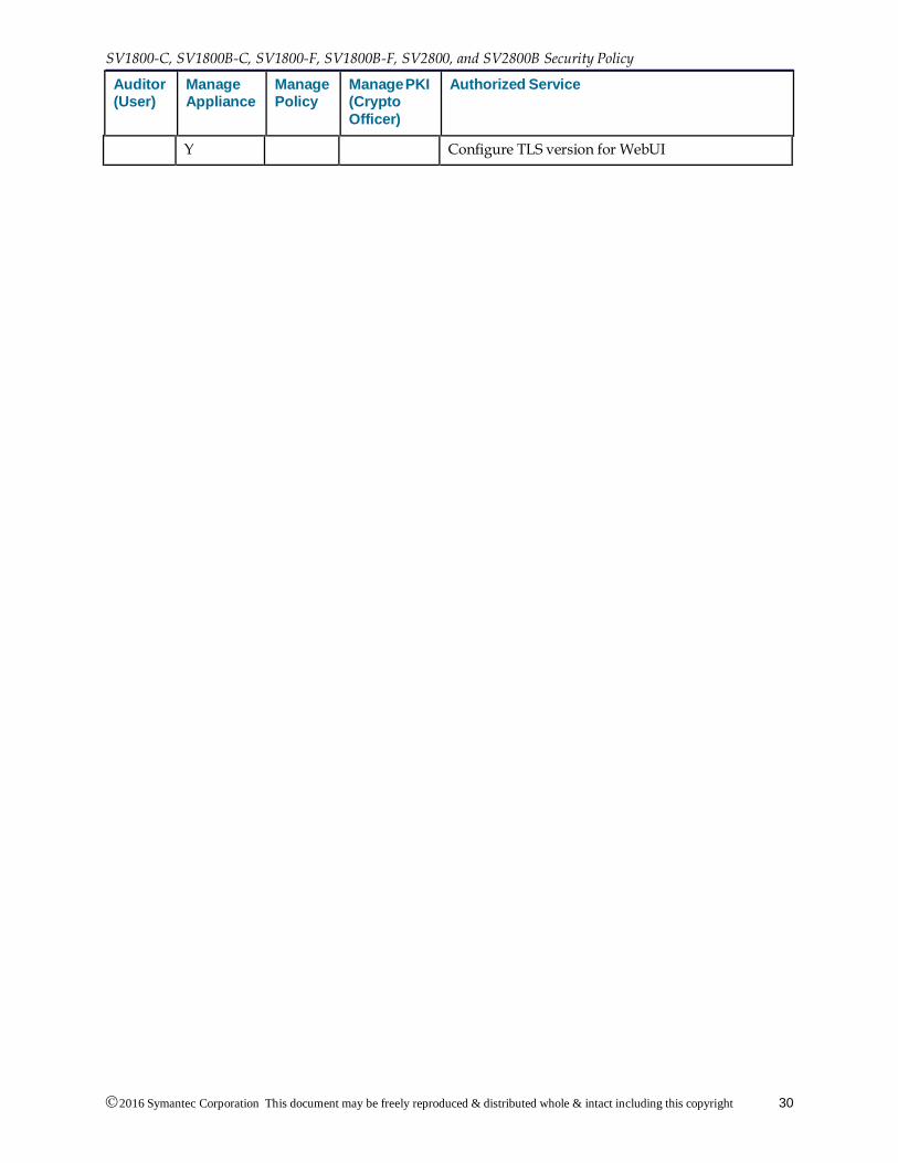
Auditor (User)
Manage Appliance
Manage Policy
Manage PKI (Crypto
Officer)
Authorized Service
Y Configure TLS version for WebUI
2016 Symantec Corporation This document may be freely reproduced & distributed whole & intact including this copyright
notice.
31
If SSL 3.0/TLS 1.0/TLS 1.1/TLS 1.2 flows using non-approved algorithms are allowed by the policy engine, the flows should be considered as "clear text" due to the use of non-approved algorithms.
Services available to a Crypto Officer and a User are described in Table 2–9. For each service listed, Crypto Officers and Users are assumed to have authenticated prior to attempting to execute the service.
The role of Auditor is equivalent to User, and the role of Manage PKI is equivalent to Crypto Officer.
The type of access to the CSPs uses the following notation:
• Read (R): The plaintext CSP is read by the service
• Write (W): The CSP is established, generated, modified, or zeroized by the service
• Execute (X): The CSP is used within an approved or allowed security function or authentication mechanism
Table 2–9 CSPs Accessed by Authorized Services
User Crypto Officer
Authorized Service CSPs
Y Unlock secure store PIN – RX KEK0 - W, X KEK1 - RX
Master keys – RX
KEK2s - RX
Object encryption keys - RX
Y Y View dashboards None
Y View system log data None
Y View/export SSL session log, SSL errors
None
Y View SSL statistics None
Y View/export intercepted certificates
Object encryption keys – X
Other entity public keys - R
Y Export diagnostic information: PKI state
Object encryption keys – X
Y Y Export diagnostic information: platform state
None
Y Export diagnostic information: SSL statistics
None
Y Y Export diagnostic information: platform interfaces and platform status statistics
None
Y View debug information: SSL statistics
None
2016 Symantec Corporation This document may be freely reproduced & distributed whole & intact including this copyright
notice.
32
SV1800-C, SV1800B-C, SV1800-F, SV1800B-F, SV2800 and SV2800B Security Policy
User Crypto Officer
Authorized Service CSPs
Y Y View debug information: NFE network statistics
None
Y View rulesets, rules, segments, and user defined lists
Object encryption keys – X
Y Create/delete/export/import internal CA keys and certificates used for re-signing
Object encryption keys - X
Resigning CA public keys - RW
Resigning CA private keys - RW
Y Delete/import external CA certificates
Object encryption keys - WX
Trusted certificate public keys - RW
Y Delete/import CRLs Object encryption keys - WX
Y Import/delete trusted certificates
Object encryption keys - WX
Trusted certificate public keys – W
Y Import/delete known keys and certificate
Object encryption keys - WX
Known public keys - W
Known private keys - W
Y View PKI information Object encryption keys – X
Other entity public keys - R
Resigning CA public keys - R
Trusted certificate public keys - R
Known public keys - R
Known private keys - R
Y Y View software, hardware details
None
Y Y View appliance settings None
Y Assign/remove Manage PKI (Crypto Officer) role
Object encryption keys - X
Y Y View user accounts Object encryption keys - X
Y View appliance settings: alerts Object encryption keys - X
2016 Symantec Corporation This document may be freely reproduced & distributed whole & intact including this copyright
notice.
33
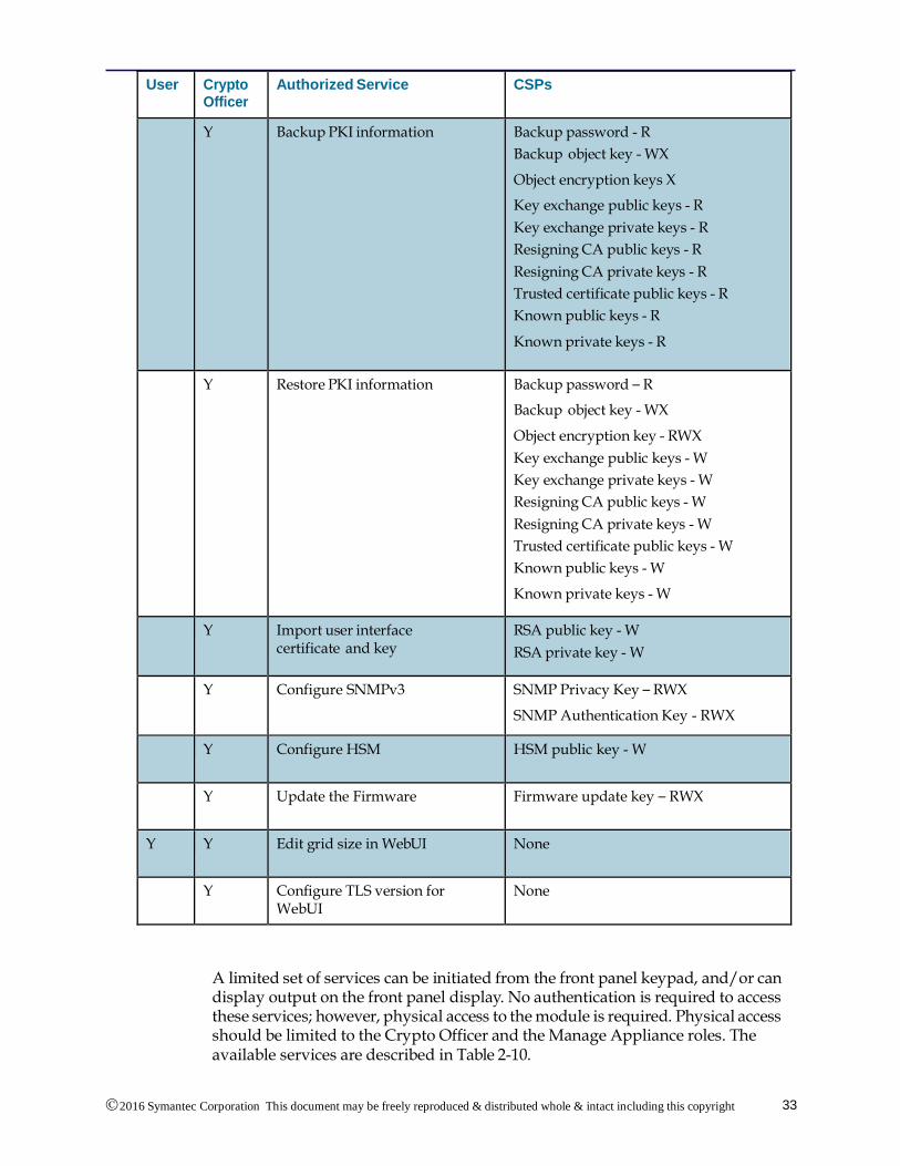
User Crypto Officer
Authorized Service CSPs
Y Backup PKI information Backup password - R
Backup object key - WX
Object encryption keys X
Key exchange public keys - R
Key exchange private keys - R
Resigning CA public keys - R
Resigning CA private keys - R
Trusted certificate public keys - R
Known public keys - R
Known private keys - R
Y Restore PKI information Backup password – R
Backup object key - WX
Object encryption key - RWX
Key exchange public keys - W
Key exchange private keys - W
Resigning CA public keys - W
Resigning CA private keys - W
Trusted certificate public keys - W
Known public keys - W
Known private keys - W
Y Import user interface certificate and key
RSA public key - W
RSA private key - W
Y Configure SNMPv3 SNMP Privacy Key – RWX
SNMP Authentication Key - RWX
Y Configure HSM HSM public key - W
Y Update the Firmware Firmware update key – RWX
Y Y Edit grid size in WebUI None
Y Configure TLS version for WebUI
None
A limited set of services can be initiated from the front panel keypad, and/or can display output on the front panel display. No authentication is required to access these services; however, physical access to the module is required. Physical access should be limited to the Crypto Officer and the Manage Appliance roles. The available services are described in Table 2-10.
2016 Symantec Corporation This document may be freely reproduced & distributed whole & intact including this copyright
notice.
34
SV1800-C, SV1800B-C, SV1800-F, SV1800B-F, SV2800 and SV2800B Security Policy
Table 2–10 Services that Do Not Require Authentication
Authorized Service Description CSPs
Hardware integrity test
Tests are run automatically at power on/restart. Error and status notifications are displayed on LEDs (see Table 2–5).
none
Firmware integrity test
Tests are run automatically at power on/restart. Error and status notifications are displayed on LCD.
Integrity test public key - RX
Force factory default reset and zeroize keys
Available from the front panel keypad and from the CLI.
Factory default reset is forced using the front panel keypad or from the CLI interface. All CSPs and all data on the disk are zeroized. The zeroization occurs while the module is still in Approved mode. See Section "3.5 Module Zeroization" on page 49.
KEK1 - W
Master keys – W
KEK2s - W
Object encryption keys - W
WebUI public key - W
WebUI private key - W
Other entity public keys - W
Key Exchange public keys - W
Key Exchange private keys - W
Resigning CA public keys - W
Resigning CA private keys - W
Trusted certificate public keys - W
Known public keys - W
Known private keys - W
TLS session keys - W
Integrity test public key - W
Operator password(s) - W
View status Keypad can be used to scroll through status information on the LCD. Status shown includes network configuration; segment status; statistics such as temperatures, fan speeds, memory utilization, CPU utilization, load; chassis serial number; version of NFE firmware matches expected version.
none
Configure network settings
Keypad can be used to configure network settings. Output is displayed on LCD.
none
Power on/reset appliance
Front panel buttons can be used to power on or reset the appliance.
Restarting the appliance includes validating the firmware. It does not include unlocking the secure store with the PIN.
Integrity test public key - RX
2016 Symantec Corporation This document may be freely reproduced & distributed whole & intact including this copyright
notice.
35
Authorized Service Description CSPs
Power off appliance
Front panel button can be used to power of the appliance.
none
Setup the module in FIPS mode
Setup the initial configuration for Approved mode of operation and initialize the secure store. See Section "3.3 Module Initialization" .
PIN – RX
KEK0 – WX
KEK1 - WX
Master keys – WX
KEK2s - WX
Object encryption keys – WX
WebUI public key - W
WebUI private key - W
Key exchange public keys - W
Key exchange private keys – W
Resigning CA public keys - W Resigning CA private keys – W
Trusted certificate public keys – W
Operator password(s) – W
2016 Symantec Corporation This document may be freely reproduced & distributed whole & intact including this copyright
notice.
36
SV1800-C, SV1800B-C, SV1800-F, SV1800B-F, SV2800 and SV2800B Security Policy
2.6 Physical Security
The SV1800-C, SV1800B-C, SV1800-F, SV1800B-F, SV2800 and SV2800B are multichip standalone cryptographic modules enclosed in a hard, opaque metal case that completely encloses the module’s internal components. Ventilation holes provided in the case either do not provide visibility to areas within the cryptographic boundary, or have mechanisms in place to obscure the view of the module’s internal components.
Tamper evident labels are fitted to provide physical evidence of attempts to remove the case in order to gain access to the module. Section "3.2 Tamper Evident Label Management and Application Instructions" shows the placement of the tamper evident labels.
Tamper evident labels are not required on Netmods (SV2800 and SV2800B only) or power supplies as these are outside the cryptographic boundary of the module.
All module components are production grade. The SV1800-C/SV1800B-C, SV1800-F, SV1800B-F, SV2800, and SV2800B have been tested and meet the EMI/EMC requirements specified by 47 Code of Federal Regulations, Part 15, Subpart B, Unintentional Radiators, Digital Devices, Class A.
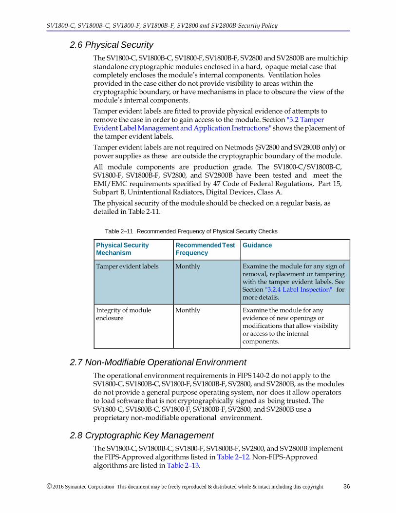
The physical security of the module should be checked on a regular basis, as detailed in Table 2-11.
Table 2–11 Recommended Frequency of Physical Security Checks
Physical Security Mechanism
Recommended Test Frequency
Guidance
Tamper evident labels Monthly Examine the module for any sign of removal, replacement or tampering with the tamper evident labels. See Section "3.2.4 Label Inspection" for more details.
Integrity of module enclosure
Monthly Examine the module for any evidence of new openings or modifications that allow visibility or access to the internal components.
2.7 Non-Modifiable Operational Environment
The operational environment requirements in FIPS 140-2 do not apply to the SV1800-C, SV1800B-C, SV1800-F, SV1800B-F, SV2800, and SV2800B, as the modules do not provide a general purpose operating system, nor does it allow operators to load software that is not cryptographically signed as being trusted. The SV1800-C, SV1800B-C, SV1800-F, SV1800B-F, SV2800, and SV2800B use a proprietary non-modifiable operational environment.
2.8 Cryptographic Key Management
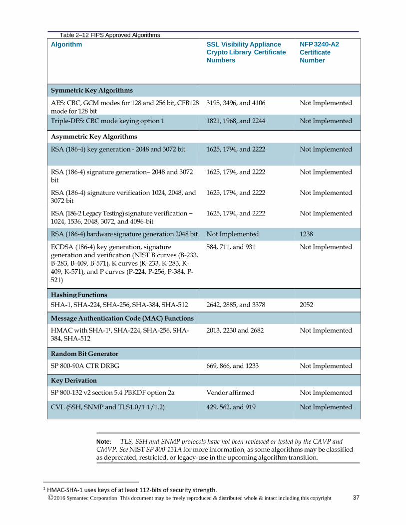
The SV1800-C, SV1800B-C, SV1800-F, SV1800B-F, SV2800, and SV2800B implement the FIPS-Approved algorithms listed in Table 2–12. Non-FIPS-Approved algorithms are listed in Table 2–13.
2016 Symantec Corporation This document may be freely reproduced & distributed whole & intact including this copyright
CVL (SSH, SNMP and TLS1.0/1.1/1.2) 429, 562, and 919 Not Implemented
Note: TLS, SSH and SNMP protocols have not been reviewed or tested by the CAVP and CMVP. See NIST SP 800-131A for more information, as some algorithms may be classified as deprecated, restricted, or legacy-use in the upcoming algorithm transition.
1 HMAC-SHA-1 uses keys of at least 112-bits of security strength.
2016 Symantec Corporation This document may be freely reproduced & distributed whole & intact including this copyright
notice.
38
SV1800-C, SV1800B-C, SV1800-F, SV1800B-F, SV2800 and SV2800B Security Policy
Table 2–13a Non-FIPS 140-2 Approved but Allowed Security Functions
Algorithm Details
RSA Management TLS sessions
Only 2048 and 3072-bit RSA key sizes are used for TLS session negotiation.
SSL/TLS Interception
RSA key sizes between 2048 and 15360-bits may be used for session negotiation during SSL/TLS interception, resigning server certificates during SSL/TLS interception, making policy decisions for SSL/TLS interception, and SSL/TLS decryption and inspection.
Key wrapping; key establishment methodology provides between 112 and 256 bits of encryption strength.
EC Diffie-Hellman Used for SSL/TLS sessions during SSL inspection.
Key size range: 224 - 571 bits
All NIST defined B, K, and P curves
Key agreement; key establishment methodology provides between 112 and 256 bits of encryption strength.
True RNG (TRNG) Implemented in hardware. Used to provide additional entropy to NDRNG.
Non-deterministic RNG (NDRNG) Used to seed SP 800-90A DRBG
Diffie-Hellman Used for SSL/TLS sessions during SSL inspection.
Diffie-Hellman public key size range: 2048 - 15360 bits
RSA PKCS #1 wrap/unwrap Used for SSL/TLS sessions. The key wrapping methodology provides between 112 and 256 bits of encryption strength.
Table 2–13b Non-FIPS 140-2 Approved and non-compliant Security Functions
Algorithm Details
RSA SSL/TLS Interception
RSA key sizes between 512 and less than 2048-bits may be used for session negotiation during SSL/TLS interception, resigning server certificates during SSL/TLS interception, making policy decisions for SSL/TLS interception, and SSL/TLS decryption and inspection.
EC Diffie-Hellman Used for SSL/TLS sessions during SSL inspection.
Key size range: 163 – less than 224 bits
All NIST defined B, K, and P curves
Curve25519 (128 bits of encryption strength)
MD5 Used for SSL/TLS sessions during SSL inspection.
2016 Symantec Corporation This document may be freely reproduced & distributed whole & intact including this copyright
notice.
39
Algorithm Details
RC4 Used for SSL/TLS sessions during SSL inspection.
Camelia Used for SSL/TLS sessions during SSL inspection.
Key sizes: 128, 256 bit keys
Mode: CBC
DES Used for SSL/TLS sessions during SSL inspection.
Mode: CBC
Diffie-Hellman Used for SSL/TLS sessions during SSL inspection.
Diffie-Hellman public key size range: 512 – less than 2048 bits
Diffie-Hellman private key size range: 96 – less than 112 bits
MD5 based HMAC Used for SSL/TLS sessions during SSL inspection.
ChaCha20-Poly1305 Used for SSL/TLS sessions during SSL inspection.
RSA PKCS #1 wrap/unwrap Used for SSL/TLS sessions. Non-compliant key wrapping methodology provides less than 112 bits of encryption strength.
Note: The algorithms listed in Table 2-13b are non-approved and non-compliant algorithms and should not be used in FIPS approved mode.
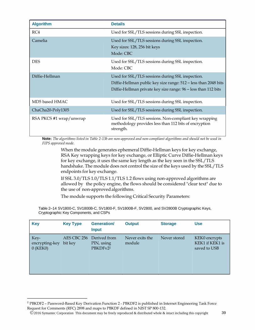
When the module generates ephemeral Diffie-Hellman keys for key exchange, RSA Key wrapping keys for key exchange, or Elliptic Curve Diffie-Hellman keys for key exchange, it uses the same key length as the key seen in the SSL/TLS handshake. The module does not control the size of the keys used by the SSL/TLS endpoints for key exchange.
If SSL 3.0/TLS 1.0/TLS 1.1/TLS 1.2 flows using non-approved algorithms are allowed by the policy engine, the flows should be considered "clear text" due to the use of non-approved algorithms.
The module supports the following Critical Security Parameters:
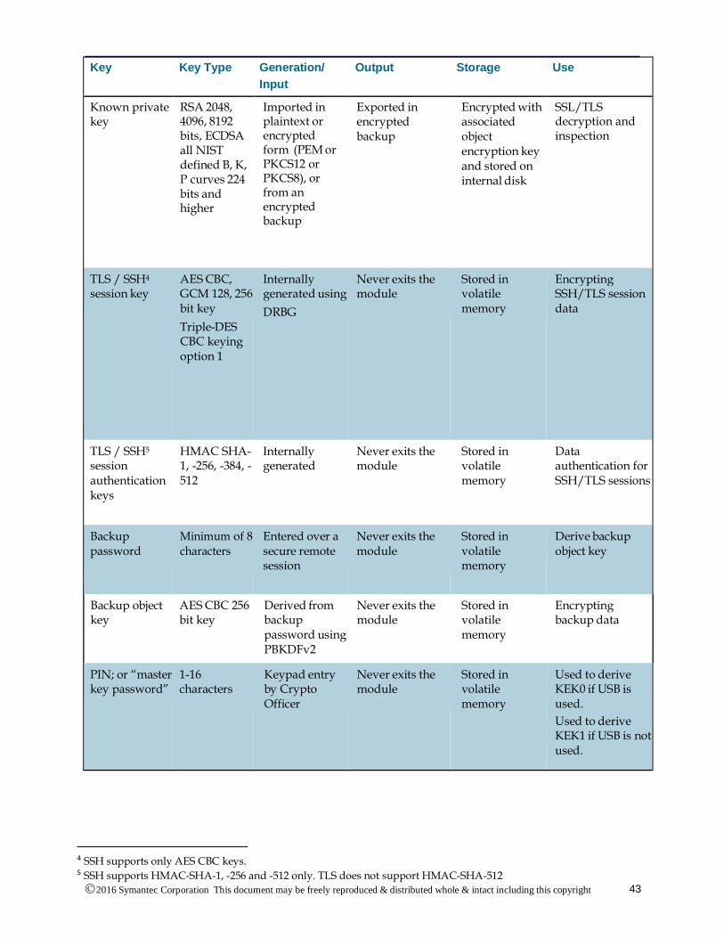
Table 2–14 SV1800-C, SV1800B-C, SV1800-F, SV1800B-F, SV2800, and SV2800B Cryptographic Keys, Cryptographic Key Components, and CSPs
Key Key Type Generation/
Input
Output Storage Use
Key-encrypting-key 0 (KEK0)
AES CBC 256 bit key
Derived from PIN, using PBKDFv22
Never exits the module
Never stored KEK0 encrypts KEK1 if KEK1 is saved to USB
2 PBKDF2 – Password-Based Key Derivation Function 2 - PBKDF2 is published in Internet Engineering Task Force
Request for Comments (RFC) 2898 and maps to PBKDF defined in NIST SP 800-132.
2016 Symantec Corporation This document may be freely reproduced & distributed whole & intact including this copyright
notice.
40
SV1800-C, SV1800B-C, SV1800-F, SV1800B-F, SV2800 and SV2800B Security Policy
Key Key Type Generation/
Input
Output Storage Use
Key-AES CBC encrypting 256 bit key -key 1 (KEK1)
AES CBC 256 bit key
Derived from PIN, using PBKDFv2, or generated using DRBG
Encrypted with KEK0 and output to USB if USB is used, otherwise never exits the module
USB stick or stored in volatile memory
KEK1 encrypts the master keys
Master key AES CBC 256 bit key
Internally generated using DRBG
Never exits the module
Encrypted using KEK1 and stored on main disk
Used to encrypt KEK2s
Key-encrypting key 2 (KEK2)
AES CBC 256 bit key
Internally generated using DRBG
Never exits the module
Encrypted using associated master key and stored on main disk
Used to encrypt object encryption keys
Object Encryption key
AES CBC 256 bit key
Internally generated using DRBG
Never exits the module
Encrypted using associated KEK2 and stored on main disk
Encrypt data and other CSPs for storage
RSA public key3
RSA 2048 and 3072 bits
Internally generated using DRBG or can be imported in plaintext
During TLS or SSH negotiation in plaintext
Stored in plaintext on internal disk
Negotiating TLS or SSH management sessions
RSA
private key
RSA 2048 and 3072 bits
Internally generated using DRBG or can be imported in plaintext
Never exits the module
Stored in plaintext on internal disk
Negotiating TLS or SSH management sessions
3 The Crypto Officer shall only import RSA 2048 bit or larger keys.
2016 Symantec Corporation This document may be freely reproduced & distributed whole & intact including this copyright
notice.
41
Key Key Type Generation/
Input
Output Storage Use
HSM public key RSA 2048 and 3072 bits imported
Imported over TLS
Exported in encrypted backup
Encrypted with associated object encryption key and stored on internal disk
HSM resigning during SSL/TLS inspection
Other entity public key
RSA 2048, 3072, 4096 8192 bits DH 2048-15360 bits; ECDSA and ECDH all NIST defined B, K, and P curves
Sent to the module in plaintext
If not intercepted, output as part of SSL/TLS handshake Viewable in plain text from WebUI
Other entities' public keys reside in volatile memory and may be cached encrypted with associated object encryption key and stored on internal disk
Negotiating SSL/TLS sessions during SSL/TLS interception
Key exchange public key
RSA 2048, 3072, 4096 8192 bits DH 2048-15360 bits; ECDSA and ECDH all NIST defined B, K, and P curves
Internally generated using DRBG Imported from an encrypted backup
Output during SSL/TLS session negotiation in plaintext. Exported in encrypted backup
Encrypted with associated object encryption key and stored on internal disk
Negotiating SSL/TLS sessions during SSL/TLS interception
Key exchange
private key
RSA 2048, 4096 bits
DH 160 - 512 bits;
ECDSA and ECDH all NIST defined B, K, and P curves 224 bits and higher
Internally generated using DRBG
Imported from an encrypted backup
Exported in Encrypted backup
Encrypted with associated object encryption key and stored on internal disk
Negotiating SSL/TLS sessions during SSL/TLS Interception
2016 Symantec Corporation This document may be freely reproduced & distributed whole & intact including this copyright
notice.
42
SV1800-C, SV1800B-C, SV1800-F, SV1800B-F, SV2800 and SV2800B Security Policy
Key Key Type Generation/
Input
Output Storage Use
Resigning CA public key
RSA 2048 bits only for internally generated RSA 2048, 3072, 4096, 8192 bits can be imported
Internally generated using DRBG. Can be imported in encrypted format (PEM or PKCS12 or PKCS8) or
plaintext, or from encrypted backup
During TLS negotiation in plaintext.
Exported in plaintext in a certificate, or in an encrypted backup
Encrypted with associated object encryption key and stored on internal disk
Resigning server certificates during SSL/ TLS interception
Resigning CA private key
RSA 2048 bits only for internally generated RSA 2048, 3072, 4096, 8192 bits can be imported
Internally generated using DRBG
Can be imported in encrypted (PEM or PKCS12 or PKCS8) or plaintext, or from encrypted backup
Exported in encrypted backup
Encrypted with associated object encryption key and stored on internal disk
Resigning server certificates during SSL/TLS interception
Trusted certificate public key
RSA 2048, 4096 bits
Imported in plaintext or encrypted form (PEM or PKCS12 or PKCS8), or from encrypted backup
Exported in encrypted backup
Encrypted with associated object encryption key and stored on internal disk
Making policy decisions for SSL/TLS interception
Known public key
RSA 2048, 4096, 8192 bits, ECDSA all NIST defined B, K, P curves 224 bits and higher
Imported in plaintext or encrypted form (PEM or PKCS12 or PKCS8), or from an encrypted backup
Exported in encrypted backup
Encrypted with associated object encryption key and stored on internal disk
SSL/TLS decryption and inspection
2016 Symantec Corporation This document may be freely reproduced & distributed whole & intact including this copyright
notice.
43
Key Key Type Generation/
Input
Output Storage Use
Known private key
RSA 2048, 4096, 8192 bits, ECDSA all NIST defined B, K, P curves 224 bits and higher
Imported in plaintext or encrypted form (PEM or PKCS12 or PKCS8), or from an encrypted backup
Exported in encrypted backup
Encrypted with associated object encryption key and stored on internal disk
SSL/TLS decryption and inspection
TLS / SSH4 session key
AES CBC, GCM 128, 256 bit key
Triple-DES CBC keying option 1
Internally generated using
DRBG
Never exits the module
Stored in volatile memory
Encrypting SSH/TLS session data
TLS / SSH5 session authentication keys
HMAC SHA-1, -256, -384, -512
Internally generated
Never exits the module
Stored in volatile memory
Data authentication for SSH/TLS sessions
Backup password
Minimum of 8 characters
Entered over a secure remote session
Never exits the module
Stored in volatile memory
Derive backup object key
Backup object key
AES CBC 256 bit key
Derived from backup password using PBKDFv2
Never exits the module
Stored in volatile memory
Encrypting backup data
PIN; or “master key password”
1-16 characters
Keypad entry by Crypto Officer
Never exits the module
Stored in volatile memory
Used to derive KEK0 if USB is used.
Used to derive KEK1 if USB is not used.
4 SSH supports only AES CBC keys. 5 SSH supports HMAC-SHA-1, -256 and -512 only. TLS does not support HMAC-SHA-512
2016 Symantec Corporation This document may be freely reproduced & distributed whole & intact including this copyright
notice.
44
SV1800-C, SV1800B-C, SV1800-F, SV1800B-F, SV2800 and SV2800B Security Policy
Key Key Type Generation/
Input
Output Storage Use
Integrity Test Public key
RSA 2048 bit key
Externally generated
Never exits the module
Plaintext on internal disk
Verifying the integrity of the system image during startup
Operator password
Minimum of 8 characters
Enters over a secure remote session
Never exits the module
Encrypted with associated object encryption key and stored on internal disk
Authenticating administrative access
SP 800-90A CTR_DRBG Seed
48 bytes Internally generated using entropy from NDRNG
Never exits the module
Plaintext in volatile memory
Seeding the FIPS approved DRBG
SP 800-90A CTR_DRBG key value
Internal state value
Internally Generated
Never exits the module
Plaintext in volatile memory
FIPS approved DRBG internal state value
SP 800-90A CTR_DRBG V value
Internal state value
Internally generated
Never exits the module
Plaintext in volatile memory
FIPS approved DRBG internal state value
SNMP Privacy Key
AES CFB128 128 bit key
Derived internally
Exported in encrypted backup
Encrypted with associated object encryption key and stored on internal disk
Encrypting SNMPv3 packets
SNMP Authentication Key
HMAC-SHA-1
Derived internally
Exported in encrypted backup
Encrypted with associated object encryption key and stored on internal disk
Authenticating SNMPv3 packets
2016 Symantec Corporation This document may be freely reproduced & distributed whole & intact including this copyright
notice.
45
Key Key Type Generation/
Input
Output Storage Use
Firmware update key
RSA 2048 bit key
Externally generated
Never exits the module
Plaintext on internal disk
Verifying the integrity of firmware updates
During the bootstrap process, you may select to have an AES-256 bit key (KEK1) stored on a removable USB drive. If the option is chosen, KEK1 is encrypted using an AES-256 bit key (KEK0) derived from the PIN prior to being stored on the USB drive. Whenever the device is power cycled or restarted, it will require this drive to be plugged in and the PIN to be input from the front panel keypad. Only with both the USB drive and the correct PIN can the master keys be unlocked to gain access the secure store. If the option is not chosen, KEK1 is derived from the PIN directly and no KEK0 is created.
KEK0 and KEK1 are derived from the PIN using the FIPS approved Password Based Key Derivation Function (PBKDF) defined in PKCS#5 v2.0; details are provided in NIST Special Publication 800-132. PBKDFv2 is implemented with HMAC-SHA-1, has its Iteration Count set to 5,000, and a 136 bit salt length (greater than the minimum is 128).
The PIN contains between 8 and 16 characters (when set using the guidance provided) that can be upper or lower case alphabetic characters or the “space” character. Keys derived from the PIN are only used for storage applications. According to NIST Special Publication 800-63 the strength of the human-generated PIN is between 18 bits and 30 bits. Thus, the probability of a random guess is between 1 in 262,144 (for 8 characters) and 1 in 1,073,741,824 (for 16 characters)).
During the bootstrap process, a set of AES 256 bit master keys are created using the internal DRBG. Master keys are encrypted with KEK1 and stored internally. The master keys are used to encrypt AES 256 bit object keys. Object keys are created using the internal DRBG and are used to encrypt data and keys for storage. Object keys are created during the bootstrap process and as needed during normal operations. Object keys are stored internally.
2.9 Self Tests
The SV1800-C, SV1800B-C, SV1800-F, SV1800B-F, SV2800, and SV2800B perform the following Power On Self Tests (POST):
• Firmware (software) integrity tests check critical O/S components and appliance software binaries using RSA signature verification (2048 bit, SHA-256)
• AES encrypt/decrypt known answer tests (KAT) on software bulk ciphers (128 bit, CBC mode)
• AES encrypt/decrypt known answer tests (KAT) on software bulk ciphers (128 bit, GCM mode)
• AES encrypt/decrypt known answer tests (KAT) on software bulk ciphers (128 bit, CFB128 mode)
2016 Symantec Corporation This document may be freely reproduced & distributed whole & intact including this copyright
notice.
46
SV1800-C, SV1800B-C, SV1800-F, SV1800B-F, SV2800 and SV2800B Security Policy
• Triple-DES encrypt/decrypt known answer tests (KAT) on software bulk ciphers (keying option 1)
• RSA known answer tests (KAT) on software signature operations (sign and verify) using the following digests (2048 bit)
• SHA-1 (verify only)
• SHA-224
• SHA-256
• SHA-384
• SHA-512
• RSA known answer tests (KAT) on hardware signature operations (sign and verify) using the following digests (2048 bit)
• SHA-1 (verify only)
• SHA-224
• SHA-256
• SHA-384
• SHA-512
• RSA known answer tests (KAT) on hardware based encryption using 2048-bit (encrypt and decrypt)
• RSA known answer tests (KAT) on software based encryption using 2048-bit (encrypt and decrypt)
• HMAC known answer tests (KAT) on software using the following digests
• SHA-1
• SHA-224
• SHA-256
• SHA-384
• SHA-512
• SHA known answer tests (KAT) on software hash for the following
• SHA-1
• SHA-224
• SHA-256
• SHA-384
• SHA-512
• SP 800-90A CTR DRBG known answer test (KAT)
• TRNG duplicate and zero output tests
• ECDSA known answer tests (KAT) (P-224, K-233 and SHA512)
All POSTs are run automatically at start-up. If an error is encountered, the system enters an error state and powers off. The firmware integrity test outputs an error message to the VGA console, serial console, and front panel LCD. Error messages for all other POSTs are output to the system log file and to the front panel LCD.
2016 Symantec Corporation This document may be freely reproduced & distributed whole & intact including this copyright
notice.
47
Once the POSTs have passed, the Crypto Officer can enter the PIN to begin the process of unlocking the secure store and allowing the system to begin operation.
The SV1800-C, SV1800B-C, SV1800-F, SV1800B-F, SV2800, and SV2800B carry out the following conditional self-tests:
• Continuous Random Number Generator test for FIPS approved SP 800-90A CTR DRBG
• Continuous NDRNG duplicate and zero output tests when seeding SP 800-90A CTR DRBG
• Continuous TRNG duplicate and zero output tests
• RSA pairwise consistency test when generating 186-4 RSA keys in software
• ECDSA pairwise consistency test when generating 186-4 ECDSA keys in software
• Firmware update test (RSA 2048 bit SHA-256)
If an error is encountered in the self-tests, the appliance will enter the error state. Error messages are output to the system log file and to the front panel LCD.
The module implements the following critical function tests:
• Adding additional entropy to non-deterministic RNG (NDRNG)
• DRBG Instantiate Critical Function Test
• DRBG Generate Critical Function Test
• DRBG Uninstantiate Critical Function Test
• DRBG Reseed Critical Function Test
If the critical function test fails, the appliance will enter the error state, and an error message is output to the system log file and to the front panel LCD.
In the event that the system enters an error state, Crypto Officer attention is required to clear the error state.
2.10 Design Assurance
Symantec uses Git for software configuration management, Cmake and Jenkins for build management, and Perforce and Agile for documentation version control.
The product is developed primarily in the high level programming languages C++, C, and Python. Assembly code is used for select performance enhancements.
The module is securely delivered from Symantec to customers via the mechanism specified by the customer. FedEx, UPS, or any other freight forwarder of their choice can be utilized.
2.11 Mitigation of Other Attacks
The module does not claim to mitigate any attacks beyond those defined in the FIPS 140-2 Level 2 requirements.
2016 Symantec Corporation This document may be freely reproduced & distributed whole & intact including this copyright
notice.
48
SV1800-C, SV1800B-C, SV1800-F, SV1800B-F, SV2800 and SV2800B Security Policy
3. Secure Operation
The SV1800-C, SV1800B-C, SV1800-F, SV1800B-F, SV2800 and SV2800B conform to FIPS 140-2 level 2 requirements. This section contains details on how to place the SV1800-C, SV1800B-C, SV1800-F, SV1800B-F, SV2800 and SV2800B into a FIPS approved mode of operation and how to maintain FIPS approved operation.
3.1 Cryptographic Officer Guidance
The Crypto Officer is responsible for initialization and management of the security relevant configuration parameters within the SV1800-C, SV1800B-C, SV1800-F, SV1800B-F, SV2800 and SV2800B. The Crypto Officer can access the SV1800-C, SV1800B-C, SV1800-F, SV1800B-F, SV2800 and SV2800B remotely using TLS. When accessed using TLS, the system provides an HTTPS graphical user interface (WebUI).
The Crypto Officer can import an RSA private key and certificate to be used by the WebUI for establishing a TLS session. The Crypto Officer shall only import RSA 2048 bit or larger keys. RSA keys less than 2048 bits are no longer approved for use as of January 1, 2014. See NIST SP 800-131A for details.
The Crypto Officer must be allowed physical access to the SV1800-C, SV1800B-C, SV1800-F, SV1800B-F, SV2800 and SV2800B. Physical access to the module shall be limited to the Crypto Officer and the Manage Appliance administrators.
Full details on how to configure and manage the SV1800-C, SV1800B-C, SV1800-F, SV1800B-F, SV2800 and SV2800B are contained in the Blue Coat Systems SSL Visibility Administration and Deployment Guide v3.8.2F, 3.8.4FC, or 3.10. This guide can be downloaded from the Symantec customer support site (https://bto.bluecoat.com).
3.2 Tamper Evident Label Management and Application Instructions
The Crypto Officer shall verify that all tamper evident labels are in place and undamaged. If a label is damaged or has been removed (in order to conduct system maintenance for example), then the Crypto Officer must ensure that the damaged or missing label is replaced, and a factory default reset must be performed on the SV1800-C, SV1800B-C, SV1800-F, SV1800B-F, SV2800 and SV2800B before proceeding.
A total of three tamper evident labels must be fitted to each module. In the event that the tamper evident labels require replacement, a pack of new labels can be purchased (P/N: FIPS-LABELS-SV).
The Crypto Officer shall be responsible for the secure storage of any label kits. The Crypto Officer shall be present whenever tamper evident labels are removed or installed to ensure security is maintained and that the module is returned to a FIPS approved state.
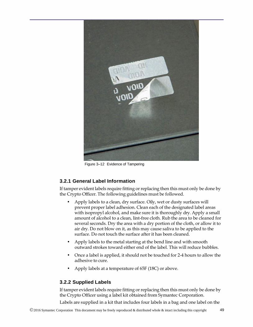
Figure 3-12 shows a tamper evident label that has been tampered with. If the “VOID” image is visible or there is other physical damage to the label, the device should not be placed into operation.
The tamper evident seals shall be installed for the module to operate in a FIPS Approved mode of operation.
The details below show the location of all tamper evident labels and also detail how to remove and replace a label if this is required.
2016 Symantec Corporation This document may be freely reproduced & distributed whole & intact including this copyright
notice.
49
Figure 3–12 Evidence of Tampering
3.2.1 General Label Information
If tamper evident labels require fitting or replacing then this must only be done by the Crypto Officer. The following guidelines must be followed.
• Apply labels to a clean, dry surface. Oily, wet or dusty surfaces will prevent proper label adhesion. Clean each of the designated label areas with isopropyl alcohol, and make sure it is thoroughly dry. Apply a small amount of alcohol to a clean, lint-free cloth. Rub the area to be cleaned for several seconds. Dry the area with a dry portion of the cloth, or allow it to air dry. Do not blow on it, as this may cause saliva to be applied to the surface. Do not touch the surface after it has been cleaned.
• Apply labels to the metal starting at the bend line and with smooth outward strokes toward either end of the label. This will reduce bubbles.
• Once a label is applied, it should not be touched for 2-4 hours to allow the adhesive to cure.
• Apply labels at a temperature of 65F (18C) or above.
3.2.2 Supplied Labels
If tamper evident labels require fitting or replacing then this must only be done by the Crypto Officer using a label kit obtained from Symantec Corporation.
Labels are supplied in a kit that includes four labels in a bag and one label on the
2016 Symantec Corporation This document may be freely reproduced & distributed whole & intact including this copyright
notice.
50
SV1800-C, SV1800B-C, SV1800-F, SV1800B-F, SV2800 and SV2800B Security Policy
bag. The two smaller labels are 1.5 x 0.6 inches, and are identical. The two larger labels are 2.875 x 1.0 inches, and are identical. The serial number on all labels and on the bag must all be the same.
Figure 3–13 FIPS Label Kit
Labels that are applied to the box have the number printed on them twice, once for each plane the label will be in. Each label goes around an edge and secures two planes.
The supplied label kit should be inspected as follows:
• If the labels do not have matching number, or if the bag has been opened, reject the labels.
• If the style of letters does not appear to be the same on all labels, reject the labels. The size of the lettering is smaller on the smaller label.
• If the labels indicate tampering, reject the labels.
The two larger labels in the bag are identical. These are applied to the edge between the top of the chassis and the sides. These labels are white with blue ink.
The two smaller labels in the bag are identical. One of these labels is applied to the top, rear cover of the chassis. The remaining label is a spare label that must be securely stored or destroyed. These labels are also white with blue ink.
The entire label packet must be rejected if the large or small labels are not identical, or if the colors are not white with blue ink.
It is not possible to purchase individual replacement labels. They are only provided as a kit. Three of the labels in the kit should be applied to the system, and the spare label stored securely or destroyed. Figure 3–13 shows a FIPS label kit; the label numbers have been obscured for security.
3.2.3 SV2800/SV2800B Label Application
The labels must be applied to the unit without the slide rail kit attached. This can be done before installation or by removing the unit from the rack.
Note: Warning. Removal of the unit may require two people and should
2016 Symantec Corporation This document may be freely reproduced & distributed whole & intact including this copyright
notice.
51
only be done by qualified personnel.
Note: Warning! Failure to follow correct procedure can cause the unit to fall and may cause damage to the unit, other equipment or injury to personnel.
If the unit is mounted in a rack, the unit must be removed. If the unit uses the standard slide kit, follow these steps:
1. Power off the unit.
2. Disconnect all cabling.
3. Provide a clean work surface for applying the labels.
4. Remove the two screws that (optionally) hold the front of the unit to the rack rails. These may not be installed.
5. Pull the unit out from the rack until it stops.
6. Slide the black arrows on the inner slide pieces forward.
7. While holding the arrows, carefully slide the chassis out of the out slide pieces.
8. Remove each inner slide piece by pressing the square button and sliding the inner slide piece toward the back of the unit. This will disengage it from all supports.
To reinstall the unit, follow the installation guide procedure.
Left Side Label Application
The left side label (one of the larger labels which is white, with blue ink) is applied between the middle and rear top covers, this is denoted label 1. It indicates tampering if either of these pieces is removed. Installation involves the following steps:
1. Peel the label from its backing.
2. Place the alignment line along the top left edge of the chassis such that the label is centered on the seam. The markings should be oriented so that the text is “up.”
3. Visually verify that continuing the application of the label will cause the screw on the left side of the rear cover panel to be fully covered.
4. Starting at the edge, press on the label and work toward the center of the top of the chassis. Ensure that no bubbles are present.
5. Again starting at the edge, press on the label and work down the left side toward the bottom of the chassis. Ensure that no bubbles are present.
6. Press firmly to all parts of the label to make sure it is fully applied.
7. Confirm that the screw on the left side is fully covered.
Right Side Label Application
The right side label (the second larger one which is white, with blue ink) is applied between the middle and rear top covers, this is denoted label 2. It
2016 Symantec Corporation This document may be freely reproduced & distributed whole & intact including this copyright
notice.
52
SV1800-C, SV1800B-C, SV1800-F, SV1800B-F, SV2800 and SV2800B Security Policy
indicates tampering if either of these pieces is removed. Installation involves the following steps:
1. Peel the label from its backing.
2. Place the alignment line along the top right edge of the chassis such that the label is centered on the seam. The markings should be oriented so that the text “up.”
3. Visually verify that continuing the application of the label will cause the screw on the right side of the rear cover panel to be fully covered. Also, the top rivet and rear indentation should be fully covered by the label.
4. Starting at the edge, press on the label and work toward the center of the top of the chassis. Ensure that no bubbles are present.
5. Again starting at the edge, press on the label and work down the right side toward the bottom of the chassis. Ensure that no bubbles are present.
6. Press firmly to all parts of the label to make sure it is fully applied.
7. Confirm that the screw on the right side is fully covered.
8. Confirm that the top rivet on the right side is fully covered.
9. Confirm that the rear indentation is fully covered.
Rear Label Application
The rear label (one of the smaller labels which is white with blue ink) is applied to the center tab on the rear top cover, this is denoted label 3.
This label has a shorter section and a longer section. The shorter section goes on the tab and the longer section goes on the top of the cover. This label indicates tampering if the screw that it covers is removed. Installation involves the following steps:
1. Orient the label so that the text is “up.”
2. Remove the label from the backing.
3. Place the alignment line along the top rear edge of the chassis. Take care to make sure that the label will be completely on the tab when it is applied. The label cannot hang over the edge of the tab.
4. Starting at the edge, press on the label and work down toward the bottom. Make sure that there are no bubbles. Make sure the screw is fully covered. Verify that the label does not hang over the edge of the tab.
5. Starting at the edge, press on the label and work toward the center of the chassis. Make sure that there are no bubbles.
6. Press firmly to all parts of the label to make sure it is fully applied.
7. Confirm that the screw on the rear tab is fully covered.
Follow the installation guide to reinstall the chassis into the rack.
The labels must be applied to the unit without the slide rail kit attached. This can be done before installation or by removing the unit from the rack.
2016 Symantec Corporation This document may be freely reproduced & distributed whole & intact including this copyright
notice.
53
Note: Warning. Removal of the unit may require two people and should only be done by qualified personnel.
Note: Warning! Failure to follow correct procedure can cause the unit to fall and may cause damage to the unit, other equipment or injury to personnel.
If the unit is mounted in a rack, the unit must be removed. If the unit uses the standard slide kit, follow these steps:
1. Power off the unit.
2. Disconnect all cabling.
3. Provide a clean work surface for applying the labels.
4. Remove the two screws that (optionally) hold the front of the unit to the rack rails. These may not be installed.
5. Pull the unit out from the rack until it stops.
6. Slide the black arrows on the inner slide pieces forward.
7. While holding the arrows, carefully slide the chassis out of the out slide pieces.
8. Remove each inner slide piece by pressing the square button and sliding the inner slide piece toward the back of the unit. This will disengage it from all supports.
To reinstall the unit, follow the installation guide procedure.
Left Side Label Application
The left side label (one of the larger labels which is white, with blue ink) is applied towards the middle of the top panel, this is denoted label 1. It indicates tampering if either of these pieces is removed. Installation involves the following steps:
1. Peel the label from its backing.
2. Place the alignment line along the middle top left edge of the chassis such that the label is centered on the seam. The markings should be oriented so that the text is “up.”
3. Starting at the edge, press on the label and work toward the center of the top of the chassis. Ensure that no bubbles are present.
4. Again starting at the edge, press on the label and work down the left side toward the bottom of the chassis. Ensure that no bubbles are present.
5. Press firmly to all parts of the label to make sure it is fully applied.
Right Side Label Application
The right side label (the second larger one which is white, with blue ink) is applied towards the middle of the top panel, this is denoted label 2. It indicates tampering if either of these pieces is removed. Installation involves the following steps:
2016 Symantec Corporation This document may be freely reproduced & distributed whole & intact including this copyright
notice.
54
SV1800-C, SV1800B-C, SV1800-F, SV1800B-F, SV2800 and SV2800B Security Policy
1. Peel the label from its backing.
2. Place the alignment line along the middle top right edge of the chassis such that the label is centered on the seam. The markings should be oriented so that the text “up.”
3. Starting at the edge, press on the label and work toward the center of the top of the chassis. Ensure that no bubbles are present.
4. Again starting at the edge, press on the label and work down the right side toward the bottom of the chassis. Ensure that no bubbles are present.
5. Press firmly to all parts of the label to make sure it is fully applied.
Rear Label Application
The rear label (one of the smaller labels which is white with blue ink) is applied to between the top panel and rear side, this is denoted label 3.
This label has a shorter section and a longer section. The shorter section goes on the rear side and the longer section goes on the top of the cover. This label indicates tampering if the cover is removed. Installation involves the following steps:
1. Orient the label so that the text is “up.”
2. Remove the label from the backing.
3. Place the alignment line along the top rear edge of the chassis. Take care to make sure that the label will not cover the ports or ventilation holes on the rear of the chassis.
4. Starting at the edge, press on the label and work down toward the bottom. Make sure that there are no bubbles.
5. Starting at the edge, press on the label and work toward the center of the chassis. Make sure that there are no bubbles.
6. Press firmly to all parts of the label to make sure it is fully applied.
Follow the installation guide to reinstall the chassis into the rack.
3.2.5 Label Inspection
The Crypto Officer must verify that all tamper evident labels are in place and undamaged. The following should be checked at regular intervals:
• Matching numbers.
• Correct colors of label and ink.
• Correct numbers if this information is recorded.
• Indications of tampering (“VOID” markings on the labels).
• Missing labels.
• Labels that do not stick properly.
• Labels that have the edges damaged.
• Discolored or distorted labels.
Following the above guidelines, tamper evident labels at three locations on the SV1800-C, SV1800B-C, S1800-F, SV1800B-F, SV2800, and SV2800B should be
2016 Symantec Corporation This document may be freely reproduced & distributed whole & intact including this copyright
notice.
55
checked in order to ensure that the unit cannot be opened in a manner that allows access to components within the cryptographic boundary. Figure 3-14 shows the location of the tamper evident label that should be fitted to the rear of the SV2800. The label is applied over the top of the screw that secures the top panel to the rest of the unit, and in such a way that it is impossible to remove the screw or to remove the top panel of the unit without the label being voided.
Figure 3–14 SV2800 Rear Panel Label Placement
Figure 3-15 shows the location of the tamper evident label that should be fitted to the rear of the SV2800B. The label is applied over the top of the screw that secures the top panel to the rest of the unit, and in such a way that it is impossible to remove the screw or to remove the top panel of the unit without the label being voided.
Figure 3–15 SV2800B Rear Panel Label Placement
Figure 3-16 shows the rear panel of the SV2800 without the label fitted. The label is affixed to the solid panel around the screw, and folds over to adhere to the top
2016 Symantec Corporation This document may be freely reproduced & distributed whole & intact including this copyright
notice.
56
SV1800-C, SV1800B-C, SV1800-F, SV1800B-F, SV2800 and SV2800B Security Policy
panel of the SV2800.
Figure 3–16 SV2800 Rear Panel without Label Fitted
Figure 3-17 shows the rear panel of the SV2800B without the label fitted. The label is affixed to the solid panel around the screw, and folds over to adhere to the top panel of the SV2800B.
Figure 3–17 SV2800B Rear Panel without Label Fitted
The remaining two labels are applied to the left and right sides of the SV2800/SV2800B and prevent the top panels from being removed.
Note: If the cooling fans need to be replaced, the top panel will need to be opened. This will void the labels. A new label kit must be installed after the top panel is opened. The module must also be factory default reset and reinstalled in FIPS approved mode.
Figure 3-18 shows the location of the side and rear labels on the SV2800/SV2800B.
2016 Symantec Corporation This document may be freely reproduced & distributed whole & intact including this copyright
notice.
57
Figure 3–18 SV2800/SV2800B Overview of Side and Back Label Positions
Figure 3-19 shows the SV2800/SV2800B with no Netmods, and with labels.
Figure 3–19 SV2800/SV2800B Top Front View with Labels, No Netmods
In the examples, references to left side and right side of the unit mean when viewed from the front. Figure 3-20 shows the location of the tamper evident label that should be fitted to the right side of the SV2800/SV2800B. The label is applied over the top of the screw that secures the top panel to the rest of the unit and in such a way that it is impossible to remove the screw or to remove the top panel of the unit without the label being voided. Figure 3-21 shows the right side of the SV2800/SV2800B without the label fitted. The label is affixed to the solid panel around the screw, and folds over to adhere to the top panel of the SV2800/SV2800B.
The corresponding labels should be applied in exactly the same manner to the left side of the SV2800/SV2800B.
2016 Symantec Corporation This document may be freely reproduced & distributed whole & intact including this copyright
notice.
58
SV1800-C, SV1800B-C, SV1800-F, SV1800B-F, SV2800 and SV2800B Security Policy
Figure 3–20 SV2800/SV2800B Right Side Label Location
Figure 3–21 SV2800/SV2800B Right Side without Label Fitted
Figure 3-22 shows the location of the tamper evident label that should be fitted to the rear of the SV1800-C, SV1800B-C, SV1800-F, and SV1800B-F. The label is applied over the top of the screw that secures the top panel to the rest of the unit, and in such a way that it is impossible to remove the screw or to remove the top panel of the unit without the label being voided.
2016 Symantec Corporation This document may be freely reproduced & distributed whole & intact including this copyright
Figure 3-23 shows the rear panel without the label fitted. The label is affixed to the solid panel around the screw, and folds over to adhere to the top panel of the SV1800-C, SV1800B-C, SV1800-F, and SV1800B-F.
Figure 3–23 SV1800-C, SV1800B-C, SV1800-F, and SV1800B-F Rear Panel without Label Fitted
The remaining two labels are applied to the left and right sides of the SV1800-C, SV1800B-C, SV1800-F, and SV1800B-F, and prevent the top panel from being removed.
Note: If the cooling fans need to be replaced, the top panel will need to be opened. This will void the labels. A new label kit must be installed after the top panel is opened. The module must also be factory default reset and reinstalled in FIPS approved mode.
Figure 3-24 shows the location of the side and rear labels on the SV1800-C and SV1800B-C.
2016 Symantec Corporation This document may be freely reproduced & distributed whole & intact including this copyright
notice.
60
SV1800-C, SV1800B-C, SV1800-F, SV1800B-F, SV2800 and SV2800B Security Policy
Figure 3–24 SV1800-C and SV1800B-C Overview of Side and Back Label Positions
Figure 3-25 shows the location of the side and rear labels on the SV1800-F and SV1800B-F.
Figure 3–25 SV1800-F and SV1800B-F Overview of Side and Back Label Positions
In the examples, references to left side and right side of the unit mean when viewed from the front. Figure 3-26 shows the location of the tamper evident label that should be fitted to the right side of the SV1800-C, SV1800B-C, SV1800-F, and SV1800B-F. The label is applied over the top of the screw that secures the top panel to the rest of the unit and in such a way that it is impossible to remove the screw or to remove the top panel of the unit without the label being voided. Figure 3-27 shows the right side of the SV1800-C, SV1800B-C, SV1800-F, and SV1800B-F without the label fitted. The label is affixed to the solid panel around the screw, and folds over to adhere to the top panel of the SV1800-C, SV1800B-C, SV1800-F, and SV1800B-F.
The corresponding labels should be applied in exactly the same manner to the left side of the SV1800-C, SV1800B-C, SV1800-F, and SV1800B-F.
2016 Symantec Corporation This document may be freely reproduced & distributed whole & intact including this copyright
notice.
61
Figure 3–26 SV1800-C, SV1800B-C, SV1800-F, and SV1800B-F Right Side Label Location
Figure 3–27 SV1800-C, SV1800B-C, SV1800-F, and SV1800B-F Right Side without Label Fitted
2016 Symantec Corporation This document may be freely reproduced & distributed whole & intact including this copyright
notice.
62
SV1800-C, SV1800B-C, SV1800-F, SV1800B-F, SV2800 and SV2800B Security Policy
3.3 Module Initialization
The SV1800-C, SV1800B-C, SV1800-F, SV1800B-F, SV2800, and SV2800B can only operate in a FIPS Approved mode of operation.
The front panel keypad, shown in Figure 3-28, has the keys arranged in the following layout
0 1
2 3
Figure 3–28 Keypad Layout
If the following key sequence is entered during the first 5 seconds after the unit is powered on a factory-default-reset will take place:
• 031203
Note: The factory default sequence only works after the LCD turns on and says "Loading..." on the second line. You have five seconds to enter the sequence at this point.
A factory default reset can also be triggered from the boot loader if a monitor and keyboard are attached to the appliance during boot.
After the factory-default-reset, the SV1800-C, SV1800B-C, SV1800-F, SV1800B-F, SV2800, and SV2800B will be in the same state as when it was originally received and will enter the bootstrap mode when powered on. Full details of the bootstrap process are provided in the Blue Coat Systems SSL Visibility SV800 and SV1800 Getting Started Guide v3.8.2F, 3.8.4FC, or 3.10.
During bootstrap mode the WebUI needs to be accessed. By default, the SV1800-C, SV1800B-C, SV1800-F, SV1800B-F, SV2800, and SV2800B will be using DHCP to acquire an IP address. The SV1800-C, SV1800B-C, SV1800-F, SV1800B-F, SV2800, and SV2800B can be configured with a static IP address, full details on the network configuration options are provided in the Blue Coat Systems SSL Visibility SV800 and SV1800 Getting Started Guide v3.8.2F, 3.8.4FC, or 3.10.
As part of the initial setup a PIN may be created. If created the PIN must be input by the Crypto Officer and a written copy stored in a secure location accessible only to the Crypto Officer. Whenever the device is power cycled or restarted it will require that the PIN be input from the front panel keypad in order to unlock the master keys, and so access the secure store.
The key sequence “01230123” must be input to enable the PIN entry mode. See the Blue Coat Systems SSL Visibility SV800 and SV1800 Getting Started Guide v3.8.2F 3.8.4FC, or 3.10 for more information.
Note: If a USB memory stick is being used for additional security, always insert it before inputting the PIN.
2016 Symantec Corporation This document may be freely reproduced & distributed whole & intact including this copyright
notice.
63
Note: During subsequent restarts of the module, if the PIN is entered incorrectly, you will not see an error. Re-input the PIN.
Once in FIPS mode, the web GUI will appear as in Figure 3-29.
Figure 3–29 Initial Bootstrap Input Screen
For best security, select the master key storage location to be USB. If the option is chosen, KEK1 is encrypted using an AES-256 bit key (KEK0) derived from the PIN prior to being stored on the USB drive. Whenever the module is power cycled or restarted, it requires this drive to be plugged in, and the PIN to be input from the front panel keypad. Only with both the USB drive and the correct PIN can the master keys be unlocked to gain access the secure store. The Crypto Officer should maintain control of the USB drive.
If the option is not chosen, only the PIN (if setup) needs to be entered when the module is power cycled or restarted.
The final stage of the bootstrap process is user setup. At least one user with the Manage Appliance role, and one user with the Manage PKI role must be created. The same user can be given one or more roles. The screen allowing configuration of user(s) with these roles is shown in Figure 3-30.
Figure 3–30 Bootstrap User Setup Screen
After creating the necessary user(s) the normal system login screen will appear allowing the user to login, at which point they will have access to the full WebUI
2016 Symantec Corporation This document may be freely reproduced & distributed whole & intact including this copyright
notice.
64
SV1800-C, SV1800B-C, SV1800-F, SV1800B-F, SV2800 and SV2800B Security Policy
to manage the SV1800-C, SV1800B-C, SV1800-F, SV1800B-F, SV2800, and SV2800B. At this point a user with the Manage Appliance role can create additional users but cannot give these users the Manage PKI role. Only a user with the Manage PKI role can give this role to a user.
3.4 Module Management
The Crypto Officer can manage the SV1800-C, SV1800B-C, SV1800-F, SV1800B-F, SV2800, and SV2800B via the WebUI (HTTPS over TLS), and the CLI. The Crypto Officer also has physical access to the module and can perform limited management functions, as detailed in Table 2–10. Detailed instructions on how to monitor and troubleshoot the SV1800-C, SV1800B-C, SV1800-F, SV1800B-F, SV2800, and SV2800B are contained in the Blue Coat Systems SSL Visibility Administration and Deployment Guide v3.8.2F, 3.8.4FC, or 3.10.
The Crypto Officer should monitor the SV1800-C, SV1800B-C, SV1800-F, SV1800B-F, SV2800, and SV2800B status regularly. Any irregular activity or reported errors should be investigated by the Crypto Officer and corrected. In the event that correction is not possible, the customer should contact Symantec Support for advice.
In case the module’s power is lost and then restored, the key used for the AES GCM encryption/decryption shall be re-distributed.
3.5 Module Zeroization
Whenever the module is being taken out of service, returned to Symantec for service, or disposed of at the end of its life, the Crypto Officer must ensure that all FIPS CSP data is zeroized. This is achieved by forcing the box to undergo a factory default reset. The Crypto Officer must wait until the factory default reset has completed and the system has returned to the bootstrap state to ensure that all data has been zeroized.
The following techniques are used during zeroization:
• Overwrite of entire disk with zeros.
• Factory default reset can only be triggered during a reboot of the appliance.
• All keys and CSPs are zeroized.
• No keys or CSPs are retained after zeroization.
• During the boot process, no remote access to the appliance is possible. After the factory default reset has been triggered during the boot process, no additional commands can be given until the reset has been completed. This prevents an attacker from influencing the zeroization procedure.
2016 Symantec Corporation This document may be freely reproduced & distributed whole & intact including this copyright