IEEE TRANSACTIONS ON INDUSTRIAL ELECTRONICS, VOL. 57, NO. 7, JULY 2010 2307
Symmetrical Hybrid Multilevel DC–AC ConvertersWith Reduced Number of Insulated DC Supplies
Domingo A. Ruiz-Caballero, Reynaldo M. Ramos-Astudillo, Samir Ahmad Mussa, Member, IEEE, andMarcelo Lobo Heldwein, Member, IEEE
Abstract—Novel symmetric hybrid multilevel topologies are in-troduced for both single- and three-phase medium-voltage high-power systems. The topology conception is presented in detail,where a three-level switching cell with low component count, andits modulation pattern give the origin of the proposed converters.Voltage sharing and low output-voltage distortion are achieved.The theoretical frequency spectra are derived. Switching devicesare separated into high- and low-frequency devices, generatinghybrid converters. Five-level three-phase topologies are generatedfrom only three insulated dc sources, while the number of semicon-ductors is the same as for the cascaded H bridge. Both simulationand experimental results are provided showing the validity of theanalysis.
Index Terms—DC–AC converters, hybrid inverters, modula-tion, symmetrical multilevel converters.
I. INTRODUCTION
H IGH-POWER three-phase medium-voltage (MV) appli-cations have been steadily growing in numbers and ap-
plications. Power electronics research in this field has beenfollowing the same trend and finding solutions in fields suchas serial connection of switches, multilevel topologies, mod-ulation techniques, cooling, and converter reliability, amongothers. In this context, multilevel topologies rise as consistentand widespread solutions to the problem [1], [2]. Variousmultilevel topologies have been proposed [3]–[8] in order toimprove performance, adapt to requirements, and avoid propri-etary technologies.
Multilevel converters have been introduced in the 1970sand 1980s [9]–[11] giving impulse to high-power conver-sion through multilevel inverters suitable to MV applications.Such converters are able to synthesize high-quality voltagewaveforms while allowing semiconductors with lower voltageratings to be employed. However, technical and economicalbarriers, such as the cost of drivers and protection, the needfor stabilizing dc supply voltages, circuit layout, and packagingcause the number of levels to be limited. Most applicationshave the number of levels given by the semiconductor voltageratings.
Manuscript received March 13, 2009; revised August 24, 2009; acceptedOctober 20, 2009. Date of publication November 20, 2009; date of currentversion June 11, 2010.
D. Ruiz-Caballero and R. Ramos-Astudillo are with the Department of Elec-trical Engineering, Pontificia Universidad Catolica de Valparaiso, Valparaiso2241, Chile (e-mail: [email protected]).
M. L. Heldwein and S. A. Mussa are with the Power Electronics Institute(INEP), Federal University of Santa Catarina (UFSC), Florianópolis 88040-970, Brazil (e-mail: [email protected]; [email protected]).
Color versions of one or more of the figures in this paper are available onlineat http://ieeexplore.ieee.org.
Digital Object Identifier 10.1109/TIE.2009.2036636
Several multilevel topologies have been proposed in theliterature [3]–[32]. Classifying the multilevel converters ac-cording to the type of voltage synthesis leads to basicallythree types of converters, namely: 1) diode-clamped convert-ers [10], [11], [25], [26]; 2) capacitor-clamped converters[4], [25], [26]; and 3) cascaded converters with insulateddc sources [3], [6], [9], [12], [15]–[20], [23], [33], [34],which are further subdivided into hybrids/nonhybrids andsymmetrical/asymmetrical. Hybrid converters are convertersthat present semiconductor switching at different frequen-cies. Symmetrical converters are converters with symmetric dcsources.
An example of asymmetrical hybrid topology is given in[17]. The converter is based on a binary configuration beingcapable of synthesizing (2N+1 − 1) voltage levels at the loadterminals, where N is the number of insulated dc sources.The converter is built with a cascade of H-bridge converterswhere some of the converters switch at a lower frequencyand are supplied with higher voltages. High-quality voltagewaveforms result from this strategy. Another inventive ap-proach is presented in [13], where semiconductors employingdifferent technologies (gate turn-off (GTOs) and insulated-gatebipolar transistors) switch at different frequencies, but the low-frequency devices still switch at frequencies higher than thefundamental.
This paper presents a novel symmetrical hybrid-converterconcept in its single- and three-phase versions. The topologiesare based on a low switch count three-level pulsewidth mod-ulation (PWM) switching cell connected to a low-frequencyswitched bridge. Thus, high modularity is achieved. Comparedwith an H-bridge cascaded multilevel converter, the numberof overall insulated dc sources is reduced in the proposedconverter, while the number of semiconductors is kept the same.Thus, the proposed concept appears as a useful and suitablesolution for MV applications where input-side insulation is re-quired along with high efficiency and modularity. Furthermore,by reducing the number of insulated dc supplies, the numberof cables connecting the input transformer terminals to therectifying bridges is reduced.
This paper is organized as follows. The derivation of thefive-level switching cell is presented in Section II. The single-and three-phase versions of the proposed concept, along withproper modulation strategies, are explained, respectively, inSections III and IV. The theoretical analysis of the load voltagesemploying the proposed modulation is performed in Section V.Finally, experimental results are presented, and conclusions aregiven.
2308 IEEE TRANSACTIONS ON INDUSTRIAL ELECTRONICS, VOL. 57, NO. 7, JULY 2010
Fig. 1. Three-level buck-type dc–dc converter (a) topology [21] and(b) modulation signals and voltage vxy .
Fig. 2. (a) Three-level buck-type dc–dc converter switching cell as a basisfor the derivation of a (b) bidirectional three-level dc–dc switching cell and anexample of an achievable (c) three-level load voltage vxy .
II. BIDIRECTIONAL MULTILEVEL CELL DERIVATION
Fig. 1(a) shows the three-level buck-type dc–dc converter[21] which is able to generate three voltage levels at the termi-nals of the output filter. The voltage vxy is illustrated in Fig. 1(b)for the given modulation pattern. In addition to the discussedcharacteristics, the converter is able to generate a voltage vxy
with double that of the switching frequency and, thus, reducefilter passive components Lo and Co. This converter employssemiconductors rated for half of the dc-link voltage and, witha proper modulation strategy, allows the balancing of the dc-link voltages by symmetrically charging and discharging thedc-link capacitors. This converter is the basis for the proposedmultilevel converter as seen in the following.
The switching cell of the three-level buck-type dc–dc con-verter shown is redrawn in Fig. 2(a). It is seen that this cellis only able to process unidirectional load currents. In orderto provide bidirectional current capability, switches S1 and S4
must employ antiparallel diodes D2 and D3 and antiparallelswitches. With this, the converter shown in Fig. 2(b) is ableto handle bidirectional load currents, and a positive three-levelload voltage vxy [cf. Fig. 2(c)] can be generated.
Fig. 3. (a) Proposed single-phase five-level symmetrical hybrid dc–ac con-verter and (b) its possible load-voltage vAN levels according to the switchedsemiconductors.
III. SINGLE-PHASE SYMMETRICAL HYBRID
MULTILEVEL CONVERTER
Considering the three-level switching cell shown in Fig. 2(b),it is possible to turn it into a dc–ac converter by properlyswitching the connection of the load terminals. This can beimplemented with the configuration shown in Fig. 3(a), whereswitches S5 to S8 are connected as a full-bridge inverter that isresponsible for switching the load terminals according to thegate signals. Fig. 3(b) shows the possible load voltage vAN
levels for the specified switching conditions. It is seen thatthe pairs S5/S8 and S6/S7 are turned on complementarily inorder to generate, respectively, negative and positive voltages.The three-level dc–dc converter switches S1 to S4 are switchedaccording to a proper modulation pattern in order to generate adesired load voltage.
Therefore, the converter shown in Fig. 3(a) is a five-levelsingle-phase inverter where switches S1 to S4 operate at highfrequency and are rated for half of the dc-link voltage E.Switches S5 to S8 are rated for the full dc-link voltage 2E.On the other hand, switches S5 to S8 can be implementedwith low-frequency devices such as GTOs, integrated gate-commutated thyristors, and others, since they switch a singletime per load-voltage period under zero voltage. Based onthis strategy, the proposed converter is a symmetric (equaldc sources) hybrid (multiple carrier frequencies) multilevelconverter. Furthermore, the number of levels can be increasedby cascading multiple single-phase converters. This can beachieved with other topologies as well.
As shown in [14] and [24], the total number of level acrossthe load terminals NAB for the proposed topology is given by
NAB = 2N + 1 (1)
where N is the total number of dc sources.
RUIZ-CABALLERO et al.: HYBRID MULTILEVEL DC–AC CONVERTERS WITH REDUCED NUMBER OF DC SUPPLIES 2309
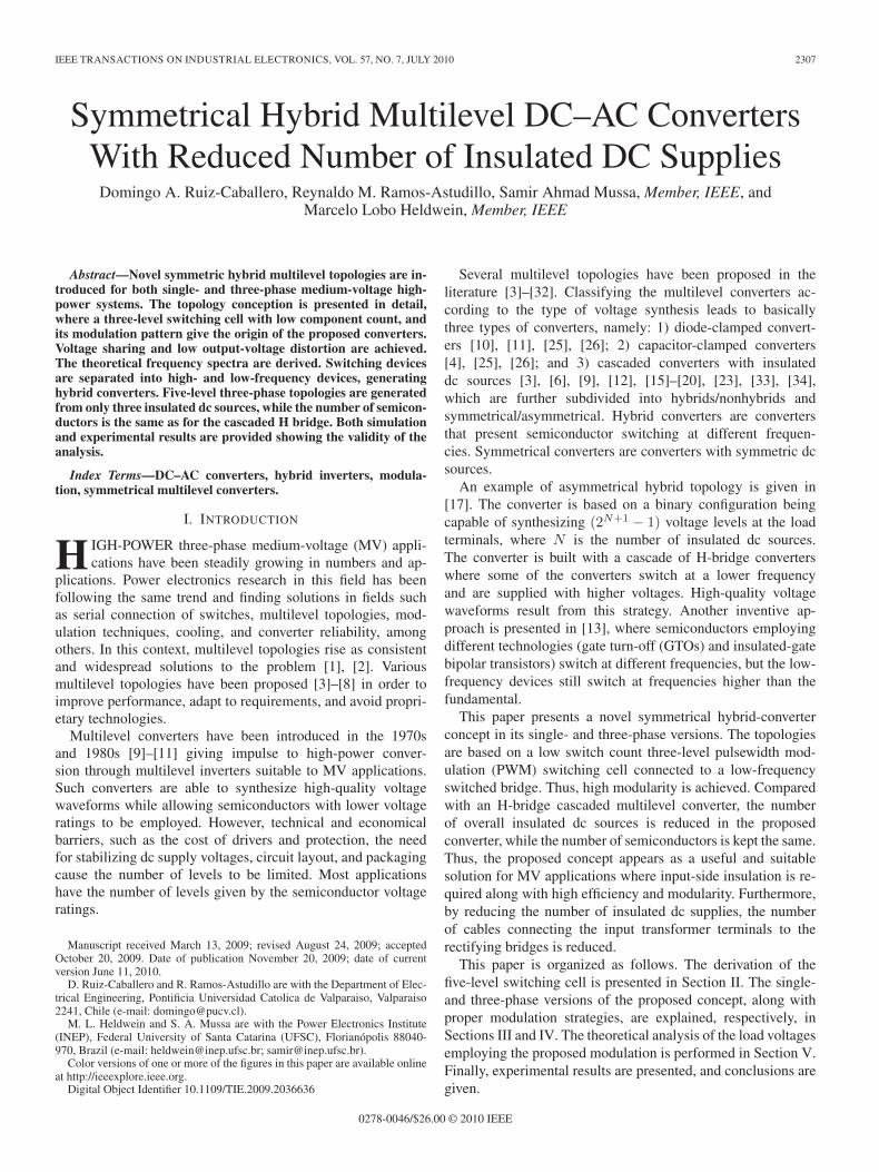
The high-frequency switches S1 to S4 are driven by PWMsignals obtained through sinusoidal unipolar PWM (S-PWM),where the gate signals are generated by the comparison ofthe modulating signal vM with triangular carriers vt1 and vt2,displaced 180◦ from each other, as shown in Fig. 4(a). The gatesignals for the low-frequency switches S5 to S8 are obtainedfrom the direct comparison of the modulating signal vM withzero. As an example, the gate pulses are shown in Fig. 4(b),and the PMW generation logic is shown in Fig. 4(c). Withthis modulation scheme, the first observed harmonic at the loadterminals appears at twice the switching frequency.
IV. THREE-PHASE SYMMETRICAL HYBRID
MULTILEVEL CONVERTER
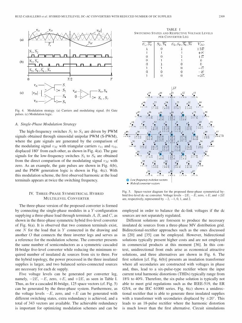
The three-phase version of the proposed converter is formedby connecting the single-phase modules in a Y -configurationsupplying a three-phase load through terminals A, B, and C, asshown in the three-phase symmetric hybrid five-level converterof Fig. 6(a). It is observed that two common terminals exist,one N for the load that is Y connected in the drawing andanother O that connects the three inverter legs and serves asa reference for the modulation scheme. The converter presentsthe same number of semiconductors as a symmetric cascadedH-bridge five-level converter while reducing the minimum re-quired number of insulated dc sources from six to three. Forthe hybrid topology, the power processed in the three insulatedsupplies is larger, and two balanced series-connected sourcesare necessary for each dc supply.
Five voltage levels can be generated per converter leg,namely, −2E, −E, zero, +E, and +2E, as seen in Table I.Thus, as for a cascaded H-bridge, 125 space vectors (cf. Fig. 5)can be generated by the three-phase system. Furthermore, asthe voltage levels −E, zero, and +E can be generated withdifferent switching states, extra redundancy is achieved, and atotal of 343 vectors are available. The achievable redundancyis important for optimizing modulation schemes and can be
TABLE ISWITCHING STATES AND RESPECTIVE VOLTAGE LEVELS
PER CONVERTER LEG
Fig. 5. Space-vector diagram for the proposed three-phase symmetrical hy-brid five-level dc–ac converter. Voltage levels −2E, −E, zero, +E, and +2Eare, respectively, represented by −2, −1, 0, 1, and 2.
employed in order to balance the dc-link voltages if the dcsources are not separately regulated.
Different solutions are foreseen to produce the necessaryinsulated dc sources from a three-phase MV distribution grid.Bidirectional-rectifier approaches such as the ones discussedin [20] and [35] can be employed. However, bidirectionalsolutions typically present higher costs and are not employedin commercial products at this moment [36]. In this con-text, unidirectional front ends arise as economical attractivesolutions, and three alternatives are shown in Fig. 6. Thefirst solution [cf. Fig. 6(b)] presents an insulation transformerwhere all secondaries are constructed with voltages in phaseand, thus, lead to a six-pulse-type rectifier where the inputcurrent total harmonic distortions (THDs) typically range from18% to 40%. Therefore, the six-pulse solution is typically notable to meet grid regulations such as the IEEE-519, the ERG5/4, or the IEC 61000 series. Fig. 6(c) shows a unidirec-tional rectifier that is able to generate three insulated supplieswith a transformer with secondaries displaced by ±20◦. Thisleads to an 18-pulse rectifier where the harmonic distortionis much lower than the first alternative. Circuit simulations
2310 IEEE TRANSACTIONS ON INDUSTRIAL ELECTRONICS, VOL. 57, NO. 7, JULY 2010
Fig. 6. Proposed (a) three-phase symmetrical hybrid five-level dc–ac converter and three different unidirectional front-end possibilities; (b) 6-pulse uncontrolledrectifier; (c) 18-pulse uncontrolled rectifier with secondaries displaced by ±20◦; and (d) 36-pulse uncontrolled rectifier with secondaries displaced by ±10◦.
of the complete multilevel converter employing the 18-pulserectifier [cf. Fig. 6(c)], output-voltage ripple of ΔVo ≤ 4%,input voltages presenting unbalances of ±3%, input inductorsLin,p.u.
∼= 5%, and leakage inductances of around Lσ,p.u.∼=
0.2% show that the input current THD approaches 10.5%, andthe highest single harmonic is typically the fifth, with 9.9%of the fundamental. Thus, compliance with international gridcodes depends on the relation between short-circuit currentsand the rated converter current or on the inclusion of tunedand/or active filters. Both 6-pulse and 18-pulse front ends donot guarantee the balance of the partial dc voltage. Thus, ifthese schemes are applied, sensoring and active control throughthe converter’s modulation should be implemented. A 36-pulseunidirectional passive rectifier is shown in Fig. 6(d), where thesecondaries of the insulation transformer are displaced by 10◦.Every two secondaries are connected in series after the diodebridges so that the balance of the partial dc-supply voltagesis guaranteed. Furthermore, simulations of this system [cf.Fig. 6(d)] supplying the multilevel converter and employing thesame parameters as with the 18-pulse simulations lead to inputcurrent THDs of around 3.71% and a higher single harmonicwith 1.62% of the fundamental at the third harmonic. Based onthe simulation results, the 36-pulse solution is able to meet themost stringent grid codes for MV networks.
A. Three-Phase Modulation Strategy
The modulation strategy is based on the single-phase mod-ulation strategy (cf. Section III-A) and employs three sinu-soidal modulating signals vMj , with j = A,B,C, displaced120◦ from each other, which are compared with two triangularcarriers vt1 and vt2 with a displacement of 180◦.
TABLE IISPECIFICATIONS FOR THE NUMERICAL SIMULATION OF THE
SINGLE-PHASE FIVE-LEVEL CONVERTER
B. Three-Phase Simulation Results
This section presents the simulation results from the three-phase five-level converter. The simulation specifications aregiven in Table II.
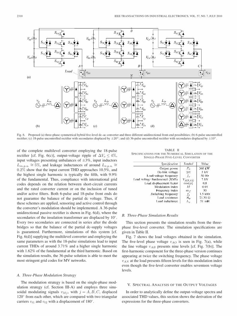
Fig. 7 shows the load voltages obtained in the simulation.The five-level phase voltage vAO is seen in Fig. 7(a), whilethe line voltage vAB presents nine levels [cf. Fig. 7(b)]. Thefirst-harmonic component for the three-phase version continuesappearing at twice the switching frequency. The phase voltagevAN at the load presents fifteen levels for this modulation indexeven though the five-level converter enables seventeen voltagelevels.
V. SPECTRAL ANALYSIS OF THE OUTPUT VOLTAGES
In order to analytically define the output-voltage spectra andassociated THD values, this section shows the derivation of theexpressions for the three-phase converters.
RUIZ-CABALLERO et al.: HYBRID MULTILEVEL DC–AC CONVERTERS WITH REDUCED NUMBER OF DC SUPPLIES 2311
Fig. 7. Simulated output voltages: (a) Phase-voltage vAO waveform.(b) Frequency spectrum of the phase voltage. (c) Line-voltage vAB waveform.(d) Spectrum of the line voltage.
A. Three-Phase Output-Voltage Analysis
The phase voltage vAO for the three-phase converter isdefined as
vAO(t) = 2E M sin(ω1t) +∞∑
n=2
∞∑v=1
4E
nπJv(nπ M)
× [sin(v ω1t + nωst) + sin(v ω1t − nωst)] (2)
where n = 2, 4, 6, . . ., v = 1, 3, 5, . . ., ω1 = 2πfo, ωs = 2πfs,and Jv(·) is the Bessel function of the fifth order.
The output line-to-line voltage for the five-level converteremploying the proposed modulation strategy is given by
vAB(t) = 2√
3E M sin(ω1t − π
6
)
+∞∑
n=2
∞∑v=1
4E
nπJv(nπ M)
× [NP sin(v ω1t + nωst + αP )
+ NN sin(v ω1t − nωst + αN )] (3)
with n = 2, 4, 6, . . ., v = 1, 3, 5, . . ., γ = 2π/3, and
NP =√
2 {1 − cos [γ(v + n)]} (4)
NN =√
2 {1 − cos [γ(v − n)]} (5)
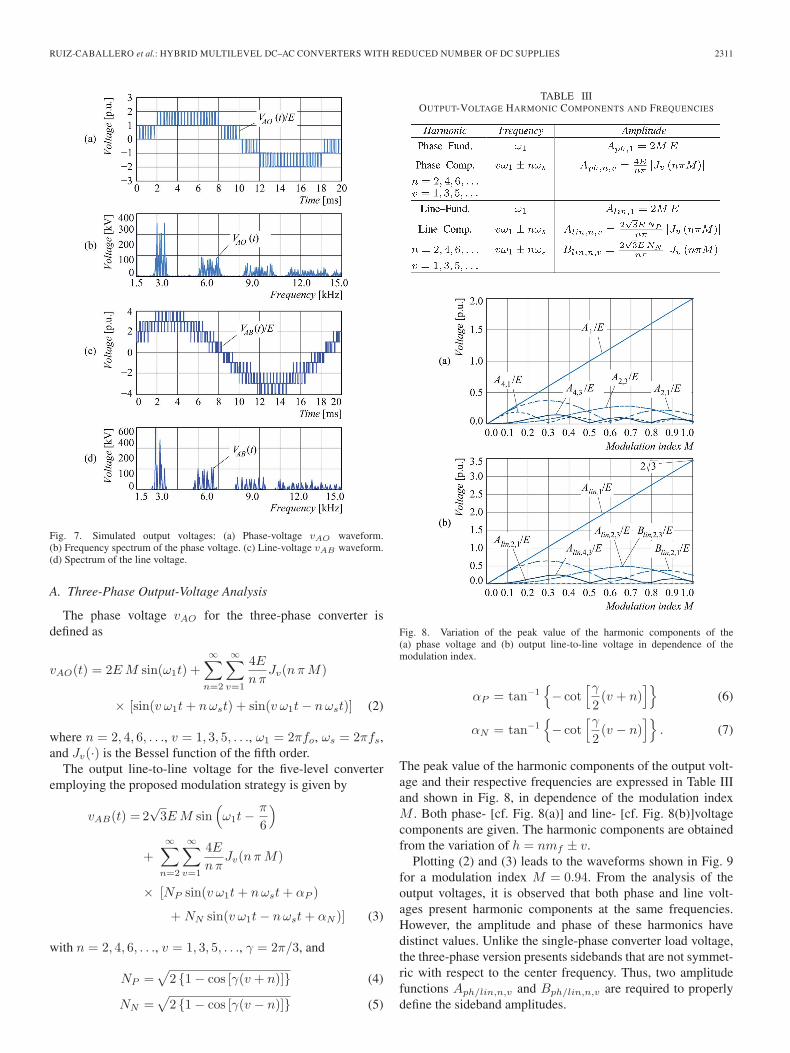
TABLE IIIOUTPUT-VOLTAGE HARMONIC COMPONENTS AND FREQUENCIES
Fig. 8. Variation of the peak value of the harmonic components of the(a) phase voltage and (b) output line-to-line voltage in dependence of themodulation index.
αP = tan−1{− cot
[γ
2(v + n)
]}(6)
αN = tan−1{− cot
[γ
2(v − n)
]}. (7)
The peak value of the harmonic components of the output volt-age and their respective frequencies are expressed in Table IIIand shown in Fig. 8, in dependence of the modulation indexM . Both phase- [cf. Fig. 8(a)] and line- [cf. Fig. 8(b)]voltagecomponents are given. The harmonic components are obtainedfrom the variation of h = nmf ± v.
Plotting (2) and (3) leads to the waveforms shown in Fig. 9for a modulation index M = 0.94. From the analysis of theoutput voltages, it is observed that both phase and line volt-ages present harmonic components at the same frequencies.However, the amplitude and phase of these harmonics havedistinct values. Unlike the single-phase converter load voltage,the three-phase version presents sidebands that are not symmet-ric with respect to the center frequency. Thus, two amplitudefunctions Aph/lin,n,v and Bph/lin,n,v are required to properlydefine the sideband amplitudes.
2312 IEEE TRANSACTIONS ON INDUSTRIAL ELECTRONICS, VOL. 57, NO. 7, JULY 2010
Fig. 9. Voltages obtained from (2) and (3) normalized with respect to half ofthe dc-link voltage E for M = 0.94.
A low-power three-phase prototype of the proposed con-verter (cf. Fig. 10) has been built in order to validate the theoret-ical analysis. The input dc voltage is set to E = 100 V, whilethe output power is 400 W. The load fundamental frequencyis fo = 50 Hz and the switching frequency fs = 1500 Hz. Anoutput filter with parameters Lo = 8 mH and Co = 8 μF perphase has been placed at the terminals of the Y -connected load.The input insulated dc sources have been generated from a220-V/60-Hz-fed three-phase transformer supplying three in-sulated secondaries connected to single-phase rectifiers andsmoothing capacitors.
The modulation strategy based on the S-PWM describedin Section IV-A is adopted. The practical implementationof the modulation algorithm is performed in a DSP, modelTMS320F2812, where the gate signals are generated in anopen-loop scheme. The modulation employs the DSP’s eventmanager (EVA and EVB) and a few I/O pins. The high-frequency PWM pulses are produced by the DSP’s PWM mod-ules, while the low-frequency signals are software generated bycomparing the modulating signals to zero. The sinusoidal refer-ences are computed internally through a routine that calculates50-Hz rectified sinusoidal signals. A zero-crossing detector is
Fig. 11. Experimental waveforms: input dc voltage 2E, phase voltage vAO ,load phase-voltage fundamental component vAN,(1), and phase current iA.
Fig. 12. Voltages across the switches SA1, SA3, SA5, and SA7.
virtually implemented in order to compare the polarity of thesinusoidal references.
Fig. 11 shows the acquired waveforms for the three-phaseconverter prototype. It is observed that the phase-voltage vAO
precisely follows the theoretical waveform while presentinga high-quality sinusoidal fundamental component vAN,(1) at50 Hz. The load phase current iA, which is filtered, follows thefundamental voltage shape. The dc voltage across one of theinputs shows the expected 120-Hz ripple and presents a meanvalue around 2E ∼= 200 V.
The voltages across the switches can be observed in Fig. 12,where the high-frequency switches SA1 and SA3 present amaximum voltage around half the value of the dc source(VSA1,max
∼= VA3,max∼= 100 V). It is observed that the low-
frequency switches withstand the full dc-link voltage (∼= 200 V)and conduct a single time per fundamental period.
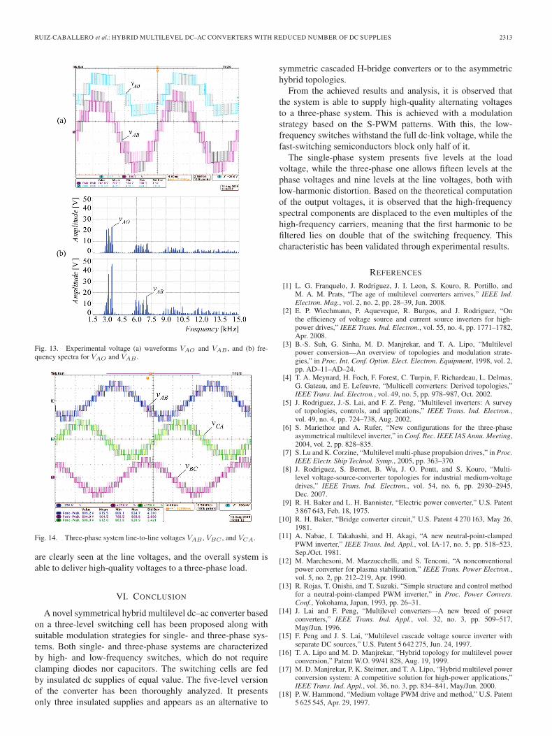
The phase and line voltages are shown in Fig. 13(a),from where the frequency spectra is computed and shown inFig. 13(b). A comparison of the experimentally obtained spec-tra and the theoretical ones shows good agreement and, thus,validates the performed analysis. In order to illustrate the three-phase operation of the built system, Fig. 14 shows the three out-put line-to-line voltages VAB , VBC , and VCA. The nine levels
RUIZ-CABALLERO et al.: HYBRID MULTILEVEL DC–AC CONVERTERS WITH REDUCED NUMBER OF DC SUPPLIES 2313
Fig. 13. Experimental voltage (a) waveforms VAO and VAB , and (b) fre-quency spectra for VAO and VAB .
Fig. 14. Three-phase system line-to-line voltages VAB , VBC , and VCA.
are clearly seen at the line voltages, and the overall system isable to deliver high-quality voltages to a three-phase load.
VI. CONCLUSION
A novel symmetrical hybrid multilevel dc–ac converter basedon a three-level switching cell has been proposed along withsuitable modulation strategies for single- and three-phase sys-tems. Both single- and three-phase systems are characterizedby high- and low-frequency switches, which do not requireclamping diodes nor capacitors. The switching cells are fedby insulated dc supplies of equal value. The five-level versionof the converter has been thoroughly analyzed. It presentsonly three insulated supplies and appears as an alternative to
symmetric cascaded H-bridge converters or to the asymmetrichybrid topologies.
From the achieved results and analysis, it is observed thatthe system is able to supply high-quality alternating voltagesto a three-phase system. This is achieved with a modulationstrategy based on the S-PWM patterns. With this, the low-frequency switches withstand the full dc-link voltage, while thefast-switching semiconductors block only half of it.
The single-phase system presents five levels at the loadvoltage, while the three-phase one allows fifteen levels at thephase voltages and nine levels at the line voltages, both withlow-harmonic distortion. Based on the theoretical computationof the output voltages, it is observed that the high-frequencyspectral components are displaced to the even multiples of thehigh-frequency carriers, meaning that the first harmonic to befiltered lies on double that of the switching frequency. Thischaracteristic has been validated through experimental results.
REFERENCES
[1] L. G. Franquelo, J. Rodriguez, J. I. Leon, S. Kouro, R. Portillo, andM. A. M. Prats, “The age of multilevel converters arrives,” IEEE Ind.Electron. Mag., vol. 2, no. 2, pp. 28–39, Jun. 2008.
[2] E. P. Wiechmann, P. Aqueveque, R. Burgos, and J. Rodriguez, “Onthe efficiency of voltage source and current source inverters for high-power drives,” IEEE Trans. Ind. Electron., vol. 55, no. 4, pp. 1771–1782,Apr. 2008.
[3] B.-S. Suh, G. Sinha, M. D. Manjrekar, and T. A. Lipo, “Multilevelpower conversion—An overview of topologies and modulation strate-gies,” in Proc. Int. Conf. Optim. Elect. Electron. Equipment, 1998, vol. 2,pp. AD–11–AD–24.
[4] T. A. Meynard, H. Foch, F. Forest, C. Turpin, F. Richardeau, L. Delmas,G. Gateau, and E. Lefeuvre, “Multicell converters: Derived topologies,”IEEE Trans. Ind. Electron., vol. 49, no. 5, pp. 978–987, Oct. 2002.
[5] J. Rodriguez, J.-S. Lai, and F. Z. Peng, “Multilevel inverters: A surveyof topologies, controls, and applications,” IEEE Trans. Ind. Electron.,vol. 49, no. 4, pp. 724–738, Aug. 2002.
[6] S. Mariethoz and A. Rufer, “New configurations for the three-phaseasymmetrical multilevel inverter,” in Conf. Rec. IEEE IAS Annu. Meeting,2004, vol. 2, pp. 828–835.
[7] S. Lu and K. Corzine, “Multilevel multi-phase propulsion drives,” in Proc.IEEE Electr. Ship Technol. Symp., 2005, pp. 363–370.
[8] J. Rodriguez, S. Bernet, B. Wu, J. O. Pontt, and S. Kouro, “Multi-level voltage-source-converter topologies for industrial medium-voltagedrives,” IEEE Trans. Ind. Electron., vol. 54, no. 6, pp. 2930–2945,Dec. 2007.
[9] R. H. Baker and L. H. Bannister, “Electric power converter,” U.S. Patent3 867 643, Feb. 18, 1975.
[10] R. H. Baker, “Bridge converter circuit,” U.S. Patent 4 270 163, May 26,1981.
[11] A. Nabae, I. Takahashi, and H. Akagi, “A new neutral-point-clampedPWM inverter,” IEEE Trans. Ind. Appl., vol. IA-17, no. 5, pp. 518–523,Sep./Oct. 1981.
[12] M. Marchesoni, M. Mazzucchelli, and S. Tenconi, “A nonconventionalpower converter for plasma stabilization,” IEEE Trans. Power Electron.,vol. 5, no. 2, pp. 212–219, Apr. 1990.
[13] R. Rojas, T. Onishi, and T. Suzuki, “Simple structure and control methodfor a neutral-point-clamped PWM inverter,” in Proc. Power Convers.Conf., Yokohama, Japan, 1993, pp. 26–31.
[14] J. Lai and F. Peng, “Multilevel converters—A new breed of powerconverters,” IEEE Trans. Ind. Appl., vol. 32, no. 3, pp. 509–517,May/Jun. 1996.
[15] F. Peng and J. S. Lai, “Multilevel cascade voltage source inverter withseparate DC sources,” U.S. Patent 5 642 275, Jun. 24, 1997.
[16] T. A. Lipo and M. D. Manjrekar, “Hybrid topology for multilevel powerconversion,” Patent W.O. 99/41 828, Aug. 19, 1999.
[17] M. D. Manjrekar, P. K. Steimer, and T. A. Lipo, “Hybrid multilevel powerconversion system: A competitive solution for high-power applications,”IEEE Trans. Ind. Appl., vol. 36, no. 3, pp. 834–841, May/Jun. 2000.
[18] P. W. Hammond, “Medium voltage PWM drive and method,” U.S. Patent5 625 545, Apr. 29, 1997.
2314 IEEE TRANSACTIONS ON INDUSTRIAL ELECTRONICS, VOL. 57, NO. 7, JULY 2010
[19] M. F. Aiello, J. M. MatesaJr., and P. W. Hammond, “Multiphase powerconverter,” U.S. Patent 6 014 323, Jan. 11, 2000.
[20] M. F. Aiello, P. W. Hammond, and M. Rastogi, “Modular multi-level adjustable supply with series-connected active inputs,” U.S. Patent6 236 580, May 22, 2001.
[21] X. Ruan, B. Li, and Q. Chen, “Three-level converters—A new approachfor high voltage and high power DC–to–DC conversion,” in Proc. PowerElectron. Spec. Conf., 2002, vol. 2, pp. 663–668.
[22] L. M. Tolbert, F. Z. Peng, T. Cunnyngham, and J. N. Chiasson, “Chargebalance control schemes for cascade multilevel converter in hybrid electricvehicles,” IEEE Trans. Ind. Electron., vol. 49, no. 5, pp. 1058–1064,Oct. 2002.
[23] K. A. Corzine, “Cascaded multi-level H-bridge drive,” U.S. Patent6 697 271, Feb. 24, 2004.
[24] F. Z. Peng, “A generalized multilevel inverter topology with self-voltage balancing,” IEEE Trans. Ind. Appl., vol. 37, no. 2, pp. 611–618,Mar./Apr. 2001.
[25] P. Steimer, P. Barbosa, and L. Meysenc, “Converter circuit for switchinga number of switching voltage levels,” Patent W.O. 2006/053 448 A1,May 26, 2006.
[26] P. Barbosa, J. Steinke, L. Meysenc, and T. Meynard, “Converter circuitfor switching a large number of switching voltage levels,” U.S. Patent7 292 460, Nov. 6, 2007.
[27] J. Dixon, A. A. Breton, F. E. Rios, J. Rodriguez, J. Pontt, and M. A. Perez,“High-power machine drive, using nonredundant 27-level inverters andactive front end rectifiers,” IEEE Trans. Power Electron., vol. 22, no. 6,pp. 2527–2533, Nov. 2007.
[28] J. Wen and K. M. Smedley, “Synthesis of multilevel converters based onsingle- and/or three-phase converter building blocks,” IEEE Trans. PowerElectron., vol. 23, no. 3, pp. 1247–1256, May 2008.
[29] J. Wen and K. M. Smedley, “Hexagram inverter for medium-voltagesix-phase variable-speed drives,” IEEE Trans. Ind. Electron., vol. 55,no. 6, pp. 2473–2481, Jun. 2008.
[30] C. H. Ng, M. A. Parker, L. Ran, P. J. Tavner, J. R. Bumby, and E. Spooner,“A multilevel modular converter for a large, light weight wind turbinegenerator,” IEEE Trans. Power Electron., vol. 23, no. 3, pp. 1062–1074,May 2008.
[31] S. Daher, J. Schmid, and F. L. M. Antunes, “Multilevel inverter topologiesfor stand-alone PV systems,” IEEE Trans. Ind. Electron., vol. 55, no. 7,pp. 2703–2712, Jul. 2008.
[32] P. Lezana, J. Rodriguez, and D. A. Oyarzun, “Cascaded multilevel inverterwith regeneration capability and reduced number of switches,” IEEETrans. Ind. Electron., vol. 55, no. 3, pp. 1059–1066, Mar. 2008.
[33] P. K. Steimer and M. D. Manjrekar, “Practical medium voltage convertertopologies for high power applications,” in Conf. Rec. IEEE IAS Annu.Meeting, 2001, vol. 3, pp. 1723–1730.
[34] O. M. Mueller and J. N. Park, “Quasi-linear IGBT inverter topologies,” inProc. Appl. Power Electron. Conf. Expo., 1994, vol. 1, pp. 253–259.
[35] J. Rodriguez, L. Moran, J. Pontt, J. L. Hernandez, L. Silva, C. Silva,and P. Lezana, “High-voltage multilevel converter with regenerationcapability,” IEEE Trans. Ind. Electron., vol. 49, no. 4, pp. 839–846,Aug. 2002.
[36] B. Wu and P. Song, “Current status of multi-megawatt AC drives,” in Proc.IEEE ICIT , 2004, vol. 1, pp. 438–443.
Domingo A. Ruiz-Caballero was born in Santi-ago, Chile, in 1963. He received the B.S. degreein electrical engineering from Pontificia UniversidadCatolica de Valparaiso, Valparaiso, Chile, in 1989,and the M.Eng. and Dr.Eng. degrees from PowerElectronics Institute (INEP), Federal University ofSanta Catarina, Florianópolis, Brazil, in 1992 and1999, respectively.
Since 2000, he has been with the Departmentof Electrical Engineering, Pontifical Catholic Uni-versity of Valparaiso, where he is currently an
Associate Professor. His fields of interest include high-frequency switchingconverters, power quality, multilevel inverters, and soft-switching techniques.
Dr. Ruiz-Caballero is currently a member of the Brazilian Power ElectronicsSociety (SOBRAEP).
Reynaldo M. Ramos-Astudillo was born in Taltal,Chile, in 1972. He received the B.S. degree inelectrical engineering and the M.Eng. degree fromPontificia Universidad Catolica de Valparaiso,Valparaiso, Chile, in 2003 and 2009, respectively.
Since 2003, he has been with the Departmentof Electrical Engineering, Pontifical Catholic Uni-versity of Valparaiso. His fields of interest includehigh-frequency switching converters, power quality,multilevel inverters, and soft-switching techniques.
Samir Ahmad Mussa (M’06) was born inJaguari-RS, Brazil, in 1964. He received the B.S.degree in electrical engineering from the FederalUniversity of Santa Maria, Santa Maria, Brazil, in1988, and a second degree in mathematics/physics.He received the M.Eng. and Ph.D. degrees in elec-trical engineering from the Federal University ofSanta Catarina (UFSC), Florianópolis, Brazil, in1994 and 2003, respectively.
He is currently an Adjunct Professor withthe Power Electronics Institute (INEP-UFSC),
Florianópolis. His research interests include digital control applied to powerelectronics, power-factor-correction techniques and DSP/FPGA applications.
Dr. Mussa is currently a member of the Brazilian Power Electronics Society(SOBRAEP).
Marcelo Lobo Heldwein (S’99–M’08) receivedthe B.S. and M.S. degrees in electrical engineer-ing from the Federal University of Santa Catarina,Florianópolis, Brazil, in 1997 and 1999, respectively,and the Dr. Sc. degree from the Swiss Federal In-stitute of Technology (ETH), Zurich, Switzerland,in 2007.
From 1999 to 2001, he was a Research Assistantwith the Power Electronics Institute, Federal Uni-versity of Santa Catarina, where he worked as aPostdocoral Fellow from 2008 to 2010. From 2001
to 2003, he was an Electrical Design Engineer with Emerson Energy Systems,in Brazil and in Sweden. He is currently an Adjunct Professor at the ElectricalEngineering Department, Federal University of Santa Catarina. His researchinterests include power factor correction techniques, static power convertersand electromagnetic compatibility.
Dr. Heldwein is currently a member of the Brazilian Power ElectronicsSociety (SOBRAEP).