2 Synchronization for OFDM-Based Systems Yu-Ting Sun and Jia-Chin Lin National Central University, Taiwan, R.O.C 1. Introduction Recently, orthogonal frequency division multiplexing (OFDM) techniques have received great interest in wireless communications for their high speed data transmission. OFDM improves robustness against narrowband interference or severely frequency-selective channel fades caused by long multipath delay spreads and impulsive noise. A single fade or interferer can cause the whole link to fail in a single carrier system. However, only a small portion of the subcarriers are damaged in a multicarrier system. In a classical frequency division multiplexing and parallel data systems, the signal frequency band is split into N nonoverlapping frequency subchannels that are each modulated with a corresponding individual symbol to eliminate interchannel interference. Nevertheless, available bandwidth utilization is too low to waste precious resources on conventional frequency division multiplexing systems. The OFDM technique with overlapping and orthogonal subchannels was proposed to increase spectrum efficiency. A high-rate serial signal stream is divided into many low-rate parallel streams; each parallel stream modulates a mutually orthogonal subchannel individually. Therefore, OFDM technologies have recently been chosen as candidates for fourth-generation (4G) mobile communications in a variety of standards, such as 802.16m and LTE/LTE-A. 2. OFDM fundamentals 2.1 System descriptions The block diagram of an OFDM transceiver is shown in Fig. 1. Information bits are grouped and mapped using M-phase shift keying (MPSK) or quadrature amplitude modulation (QAM). Because an OFDM symbol consists of a sum of subcarriers, the th n − 1 N × mapped signal symbol n X is fed into the modulator using the inverse fast Fourier transform (IFFT). Then, the modulated signal n x can be written as 1 2 0 1 , 0,1, , -1 N j kn N n k k x Xe n N N π − = = = ∑ " (1) where N is the number of subcarriers or the IFFT size, k is the subcarrier index, n is the time index, and 1 N is the normalized frequency separation of the subcarriers. Note that n x and k X form an point N − discrete Fourier transform (DFT) pair. The relationship can be expressed as www.intechopen.com
Transcript
2
Synchronization for OFDM-Based Systems
Yu-Ting Sun and Jia-Chin Lin National Central University, Taiwan,
R.O.C
1. Introduction
Recently, orthogonal frequency division multiplexing (OFDM) techniques have received great interest in wireless communications for their high speed data transmission. OFDM improves robustness against narrowband interference or severely frequency-selective channel fades caused by long multipath delay spreads and impulsive noise. A single fade or interferer can cause the whole link to fail in a single carrier system. However, only a small portion of the subcarriers are damaged in a multicarrier system. In a classical frequency division multiplexing and parallel data systems, the signal frequency band is split into N nonoverlapping frequency subchannels that are each modulated with a corresponding individual symbol to eliminate interchannel interference. Nevertheless, available bandwidth utilization is too low to waste precious resources on conventional frequency division multiplexing systems. The OFDM technique with overlapping and orthogonal subchannels was proposed to increase spectrum efficiency. A high-rate serial signal stream is divided into many low-rate parallel streams; each parallel stream modulates a mutually orthogonal subchannel individually. Therefore, OFDM technologies have recently been chosen as candidates for fourth-generation (4G) mobile communications in a variety of standards, such as 802.16m and LTE/LTE-A.
2. OFDM fundamentals
2.1 System descriptions
The block diagram of an OFDM transceiver is shown in Fig. 1. Information bits are grouped and mapped using M-phase shift keying (MPSK) or quadrature amplitude modulation (QAM). Because an OFDM symbol consists of a sum of subcarriers, the thn − 1N × mapped signal symbol nX is fed into the modulator using the inverse fast Fourier transform (IFFT). Then, the modulated signal nx can be written as
1
2
0
1, 0,1, , - 1
Nj kn N
n kk
x X e n NN
π−=
= =∑ A (1)
where N is the number of subcarriers or the IFFT size, k is the subcarrier index, n is the time index, and 1 N is the normalized frequency separation of the subcarriers. Note that nx and kX form an pointN − discrete Fourier transform (DFT) pair. The relationship can be expressed as
www.intechopen.com
Recent Advances in Wireless Communications and Networks
24
{ } 12 /
0
1DFT , 0,1, , - 1
Nj kn N
n N n kk
X x x e n NN
π− −=
= = =∑ A (2)
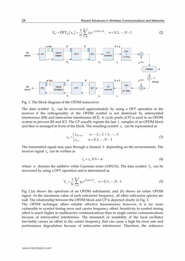
Fig. 1. The block diagram of the OFDM transceiver
The data symbol kX can be recovered approximately by using a DFT operation at the receiver if the orthogonality of the OFDM symbol is not destroyed by intersymbol interference (ISI) and intercarrier interference (ICI). A cyclic prefix (CP) is used in an OFDM system to prevent ISI and ICI. The CP usually repeats the last L samples of an OFDM block and then is arranged in front of the block. The resulting symbol ns can be represented as
, , 1, , 1
, 0,1, , 1N n
nn
x n L Ls
x n N+ = − − + −⎧= ⎨ = −⎩
AA
(3)
The transmitted signal may pass through a channel h depending on the environments. The receiver signal nr can be written as
n nr s h w= ⊗ + (4)
where w denotes the additive white Gaussian noise (AWGN). The data symbol nY can be recovered by using a DFT operation and is determined as
1
2
0
1, 0,1, , - 1
Nj kn N
n kk
Y y e n NN
π−=
= =∑ A (5)
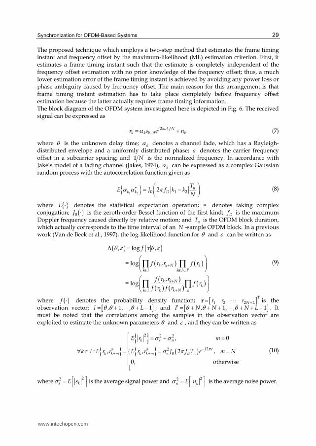
Fig. 2 (a) shows the spectrum of an OFDM subchannel, and (b) shows an entire OFDM signal. At the maximum value of each subcarrier frequency, all other subcarrier spectra are null. The relationship between the OFDM block and CP is depicted clearly in Fig. 3. The OFDM technique offers reliable effective transmission; however, it is far more vulnerable to symbol timing error and carrier frequency offset. Sensitivity to symbol timing offset is much higher in multicarrier communications than in single carrier communications because of intersymbol interference. The mismatch or instability of the local oscillator inevitably causes an offset in the carrier frequency that can cause a high bit error rate and performance degradation because of intercarrier interference. Therefore, the unknown
www.intechopen.com
Synchronization for OFDM-Based Systems
25
OFDM symbol arrival times and mismatch/instability of the oscillators in the transmitter and the receiver are two significant synchronization problems in the design of OFDM communications. A detailed description of symbol timing error and carrier frequency offset is given in the following sections.
-6 -4 -2 0 2 4 6-0.4
-0.2
0
0.2
0.4
0.6
0.8
1
Frequency -6 -4 -2 0 2 4 6
-0.4
-0.2
0
0.2
0.4
0.6
0.8
1
Frequency
(a) (b)
Fig. 2. Spectra of (a) an OFDM subchannel and (b) an OFDM signal
Fig. 3. An OFDM symbol with a cyclic prefix
2.2 Synchronization issues 2.2.1 Timing offset
OFDM systems exploit their unique features by using a guard interval with a cyclic prefix to eliminate intersymbol interference and intercarrier interference. In general, the symbol timing offset may vary in an interval that is equal to the guard time and does not cause intersymbol interference or intercarrier interference. OFDM systems have more robustness to compare with carrier frequency offset. However, a problem arises when the sampling
www.intechopen.com
Recent Advances in Wireless Communications and Networks
26
frequency does not sample an accurate position; the sensitivity to symbol timing offset increases in OFDM systems. Receivers have to be tracked time-varying symbol timing offset, which results in time-varying phase changes. Intercarrier interference comes into being another attached problem. Because an error in the sampling frequency means an error in the FFT interval duration, the sampled subcarriers are no longer mutually orthogonal. The deviation is more severe as the delay spread in multipath fading increases; then, the tolerance for the delay spread is less than the expected value. As a result, timing synchronization in OFDM systems is an important design issue to minimize the loss of robustness.
2.2.2 Carrier frequency offset
In section 2.1, it is evident that at all OFDM subcarriers are orthogonal to each other when they have a different integer number of cycles in the FFT interval. The number of cycles is not an integer in FFT interval when a frequency offset exists. This phenomenon leads to intercarrier interference after the FFT. The output of FFT for each subcarrier contains an interfering term with interference power that is inversely proportional to the frequency spacing from all other subcarriers (Nee & Prasad, 2000). The amount of intercarrier interference for subcarriers in the middle of the OFDM spectrum is roughly twice as larger as that at the OFDM band edges because there are more interferers from interfering subcarriers on both sides. In practice, frequency-selective fading from the Doppler effect and/or mismatch and instability of the local oscillators in the transmitter and receiver cause carrier frequency offset. This effect invariably results in severe performance degradation in OFDM communications and leads to a high bit error rate. OFDM systems are more sensitive to carrier frequency offset; therefore, compensating frequency errors are very important.
3. Application scenarios
The major objectives for OFDM synchronization include identifying the beginning of individual OFDM symbol timing and ensuring the orthogonality of each subcarrier. Various algorithms have been proposed to estimate symbol timing and carrier frequency offset. These methods can be classified into two categories: data-aided algorithms and non-data-aided (also called blind) algorithms. By using known training sequences or pilot symbols, a data-aided algorithm can achieve high estimation accuracy and construct the structure simply. Data-aided algorithms require additional data blocks to transmit known synchronization information. Nevertheless, this method diminishes the efficiency of transmission to offer the possibility for synchronization. Non-data-aided (blind) algorithms were proposed to solve the inefficiency problem of the data-aided algorithm. Alternative techniques are based on the cyclic extension that is provided in OFDM communication systems. These techniques can achieve high spectrum efficiency but are more complicated. In the data-aided technique, several synchronization symbols are directly inserted between the transmitted OFDM blocks; then, these pilot symbols are collected at the receiving end to extract frame timing information. However, the use of pilot symbols inevitably decreases the capacity and/or throughput of the overall system, thus making them suitable only in a startup/training mode. The data- aided technique can provide effectively synchronization with very high accuracy. Thus, it can be used to find coarse timing and frequency offset in the initial communication link. Several data-aided techniques have been proposed (Classen & Meyr, 1994, Daffara & Chouly, 1993, Kapoor et al., 1998, Luise & Reggiannini, 1996, Moose, 1994, Warner & Leung, 1993). Moreover, the SNR at the front end in the receiver is often too
www.intechopen.com
Synchronization for OFDM-Based Systems
27
low to ineffectively detect pilot symbols; thus, a blind approach is usually much more desirable. A non-data-aided technique can adjust the fine timing and frequency after the preamble signal. Some non-data-aided techniques have been proposed (Bolcskei, 2001, Daffara & Adami, 1995, Lv et al., 2005, Okada et al., 1996, Park et al., 2004, Van de Beek et al., 1997).
3.1 Non-data-aided method
The cyclic extension has good correlation properties because the initial CPT seconds of each symbol are the same as the final seconds in OFDM communications. The cyclic prefix is used to evaluate the autocorrelation with a lag of T . When a peak is found in the correlator output, the common estimates of the symbol timing and the frequency offset can be evaluated jointly. The correlation output can be expressed as
*
0( ) ( ) ( )
CPTx t r t r t T dτ τ τ= − − −∫ (6)
where ( )r t is the received OFDM signal, ( )x t is the correlator output, τ denotes the timing offset. The correlator output can be utilized to estimate the carrier frequency offset when the symbol timing is found. The phase drift between T seconds is equivalent to the phase of the correlator output. Therefore, the carrier frequency offset can be estimated easily by dividing the correlator phase by 2 Tπ . The carrier frequency offset denotes the frequency offset normalized by the subcarrier spacing. Fig. 4 shows the block diagram of the correlator.
Fig. 4. Correlator using the cyclic prefix
3.2 Data-aided method
Although data-aided algorithms are not efficient for transmission, they have high estimation accuracy and a simple architecture which are especially important for packet transmission. The synchronization time needs to be as short as possible, and the accuracy must be as high as possible for high rate packet transmission (Nee & Prasad, 2000). Special OFDM training sequences in which the data is known to the receiver were developed to satisfy the requirement for packet transmission. The absolute received training signal can be exploited for synchronization, whereas non-data-aided algorithms that take advantage of cyclic extension only use a fraction signal of each symbol. In training sequence methods, the matched filter is used to estimate the symbol timing and carrier frequency offset. Fig. 5 shows a block diagram of a matched filter. The input signal is the known OFDM training sequence. The sampling interval is denoted as T . The elements of { }0 1 1Nc c c −A are the matched filter coefficients which are the complex signals of the known training sequence. The symbol timing and carrier offset can be achieved by searching for the correlation peak accumulated from matched filter outputs.
www.intechopen.com
Recent Advances in Wireless Communications and Networks
28
Fig. 5. Matched filter for the OFDM training sequence
4. Examples
4.1 Example 1: Non-data-aided, CP-based, fractional/fine frequency offset
According to previous researches, very high computational complexity is required for joint estimation for timing and frequency synchronization. Moreover, one estimate suffers from performance degradation caused by estimation error of the other. Thus, an effective technique is proposed (Lin, 2003).
Fig. 6. The OFDM transceiver (Lin, 2003)
www.intechopen.com
Synchronization for OFDM-Based Systems
29
The proposed technique which employs a two-step method that estimates the frame timing instant and frequency offset by the maximum-likelihood (ML) estimation criterion. First, it estimates a frame timing instant such that the estimate is completely independent of the frequency offset estimation with no prior knowledge of the frequency offset; thus, a much lower estimation error of the frame timing instant is achieved by avoiding any power loss or phase ambiguity caused by frequency offset. The main reason for this arrangement is that frame timing instant estimation has to take place completely before frequency offset estimation because the latter actually requires frame timing information. The block diagram of the OFDM system investigated here is depicted in Fig. 6. The received signal can be expressed as
2 /j k Nk k k kr s e nπεθα −= + (7)
where θ is the unknown delay time; kα denotes a channel fade, which has a Rayleigh-distributed envelope and a uniformly distributed phase; ε denotes the carrier frequency offset in a subcarrier spacing; and 1 N is the normalized frequency. In accordance with Jake’s model of a fading channel (Jakes, 1974), kα can be expressed as a complex Gaussian random process with the autocorrelation function given as
{ }1 2 0 1 22 u
k k D
TE J f k k
Nα α π∗ ⎛ ⎞= −⎜ ⎟⎝ ⎠ (8)
where {}E ⋅ denotes the statistical expectation operation; ∗ denotes taking complex conjugation; ( )0J ⋅ is the zeroth-order Bessel function of the first kind; Df is the maximum Doppler frequency caused directly by relative motion; and uT is the OFDM block duration, which actually corresponds to the time interval of an N -sample OFDM block. In a previous work (Van de Beek et al., 1997), the log-likelihood function for θ and ε can be written as
( ) ( )( ) ( )( )( ) ( ) ( )
, log ,
= log ,
, = log
k k N kk I k I I
k k Nk
k k Nk I k
f
f r r f r
f r rf r
f r f r
θ ε θ ε+ ′∈ ∉ ∪++∈
Λ =⎛ ⎞⎜ ⎟⎜ ⎟⎝ ⎠⎛ ⎞⎜ ⎟⎜ ⎟⎝ ⎠
∏ ∏∏ ∏
r
(9)
where ( )f ⋅ denotes the probability density function; [ ]1 2 2T
N Lr r r +=r A is the observation vector; [ ], 1, , 1I Lθ θ θ= + + −A ; and [ ], 1, , 1I N N N Lθ θ θ′ = + + + + + −A . It must be noted that the correlations among the samples in the observation vector are exploited to estimate the unknown parameters θ and ε , and they can be written as
{ } { }{ } ( )2 2 2
220
, 0
: , , 2 ,
0, otherwise
k s n
jk k m k k m s D u
E r m
k I E r r E r r J f T e m Nπεσ σ
σ π −∗ ∗+ +
⎧ = + =⎪⎪∀ ∈ = = =⎨⎪⎪⎩ (10)
where 22
s kE sσ ⎡ ⎤= ⎣ ⎦ is the average signal power and 22
n kE nσ ⎡ ⎤= ⎣ ⎦ is the average noise power.
www.intechopen.com
Recent Advances in Wireless Communications and Networks
30
Because the product ( )kkf r∏ in (9) is independent of θ and ε , it can be dropped when
maximizing ( ),θ εΛ . Under the assumption that r is a jointly Gaussian vector and after
some manipulations reported in the reference Appendix (Lin, 2003), (9) can be rewritten as
( ) { } ( )
( ){ } ( ) ( ){ } ( ) ( )1 1
2 221 2
1 2 1 1 2
, Re2
Re cos 2 Im sin 2
L Lj
k k m k k Nk k
c c r r e r r
c c
θ θπεθ θ
ρθ ελ θ πε λ θ πε ρλ θ
+ − + −−∗+ += =⎡ ⎤Λ = + − +⎢ ⎥⎣ ⎦⎡ ⎤= + − −⎣ ⎦∑ ∑
(11)
where
{ }{ } { } ( )20
2 22 2
2k k N s D u
s nk k N
E r r J f T
E r E r
σ πρ σ σ∗+
+= = +
( )12
1 log 1L
k
cθ
θρ+ −
== − −∑
( )( )2 2 2 2
2
1 s n
cρ
ρ σ σ= − +
( ) 1
1
L
k k Nk
r rθ
θλ θ + − ∗+=
= ∑
( ) { }12 2
2
1
2
L
k k Nk
r rθ
θλ θ + −
+== +∑
In the above equation, it is assumed that the random frequency modulation caused by a time-varying channel fade and the phase noise of the local oscillator are negligible; thus, { }k k Nr r∗+ has almost the same phase within the range [ ], 1k Lθ θ∈ + − ; therefore, { }k k Nr r∗+ can be coherently summed up in the term ( )1λ θ . If the partial derivative of ( ),θ εΛ is taken with respect to ε , one can obtain the following equation:
( ) ( ){ } ( ) ( ){ } ( )2 1 1, 2 Re sin 2 Im cos 2cθ ε π λ θ πε λ θ πεε∂ ⎡ ⎤Λ = − +⎣ ⎦∂ (12)
To obtain the value of ε̂ that maximizes ( ),θ εΛ , the above partial derivative is set to zero and equality stands only when
( ){ }( ) ( ){ }( )1 1
3
Re Im 1
cos 2 sin 2 c
λ θ λ θπε πε= =− (13)
where 3c is set as a constant 1 L for simplicity. As a result, the carrier frequency offset estimate can be expressed as
( ){ }( ){ }11
1
Im1ˆ tan
2 Re
λ θε π λ θ− ⎛ ⎞= − ⎜ ⎟⎜ ⎟⎝ ⎠ (14)
www.intechopen.com
Synchronization for OFDM-Based Systems
31
The carrier frequency offset estimator derived above actually requires accurate frame timing information to effectively resolve the carrier frequency offset by taking advantage of a complete cyclic prefix. As a result, accurate frame timing estimation has to be performed before a carrier frequency offset is estimated. To develop a frame timing estimation scheme without prior knowledge of frequency offset, the log-likelihood function in (11) can be approximated as follows:
Thus, one can obtain a frame timing estimator independent of frequency offset estimation. The proposed technique provides a more practical estimate of the frame timing instant because frame timing estimation is very often performed before frequency offset is estimated or dealt with. As a result, the proposed estimator of the frame timing instant and frequency offset can be expressed as
( ) ( ){ }( ){ }( ){ }2
3 1 2
11
1
ˆStep 1: arg max
ˆIm1ˆStep 2: tan
ˆ2 Re
p
p
p
p
cθθ λ θ ρλ θλ θε π λ θ
−
⎧ = −⎪⎪ ⎛ ⎞⎨ ⎜ ⎟⎪ = − ⎜ ⎟⎪ ⎜ ⎟⎝ ⎠⎩ (16)
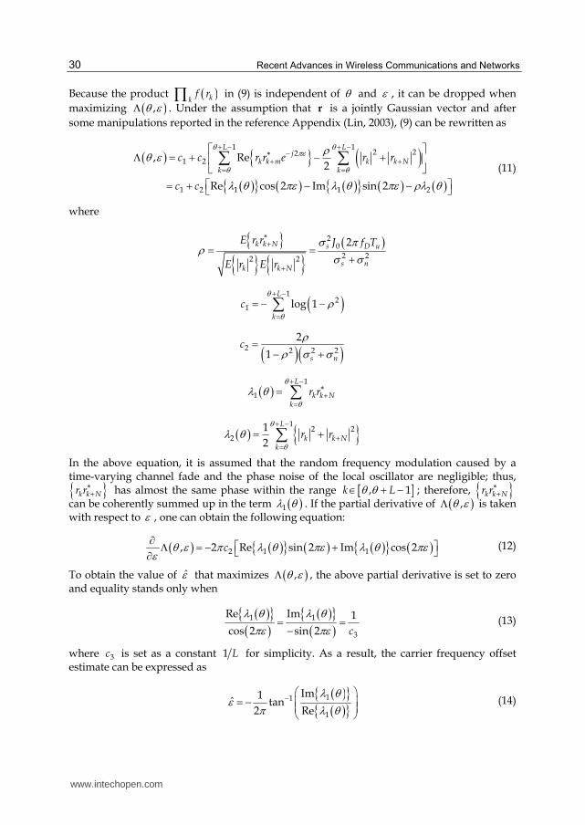
Its structure is depicted in detail in Fig. 7. The proposed frame timing estimator inherently exploits the highest signal level by disregarding any phase ambiguity caused by residual error in frequency offset estimation. Therefore, the proposed technique performs frame timing estimation in a manner independent of frequency offset estimation; then, frequency offset estimation can be properly achieved in the next step by effectively taking advantage of accurate timing information.
Fig. 7. The estimator (Lin, 2003)
Because the effect of fast channel fading is considered here, the proposed technique has to account for a maximum Doppler frequency fD on the same order of 1/Tu. Therefore, the proposed estimator of the frame timing instant is often dominated by its first term because the correlation coefficient term ρ in (16) approaches zero in such an environment. As a result, estimating of the frame timing instant can be simplified as follows to reduce the hardware complexity:
www.intechopen.com
Recent Advances in Wireless Communications and Networks
32
( ){ }2
1ˆ arg maxp θθ λ θ′ = (17)
In addition, several techniques for combining multiple frames have also been investigated (Lin, 2003) to increase the robustness of the proposed technique under low SNR conditions. Other simulation experiments show that the proposed techniques can effectively achieve lower estimation errors in frame timing and frequency offset estimation.
4.2 Example 2: Data-aided, preamble, integral/coarse frequency offset
Previous works often employ signal-estimation techniques on a time-indexed basis in the time direction. However, very few previous works have dealt with frequency-offset problems by applying a detection technique on a subcarrier-indexed basis in the frequency direction. An effective technique for frequency acquisition based on maximum-likelihood detection for mobile OFDM is proposed. The proposed technique employs a frequency-acquisition stage and a tracking stage. We mainly focus on frequency acquisition because tracking has been investigated (Lin, 2004, 2006b, 2007). By exploiting differential coherent detection of a single synchronization sequence, where a pseudonoise (PN) sequence is used as a synchronization sequence, we can prove that data-aided frequency acquisition with frequency-directional PN matched filters (MFs) reduces the probabilities of false alarm and miss on a channel with a sufficiently wide coherence bandwidth. Strict statistical analyses have been performed to verify the improvements achieved. Furthermore, the proposed technique can operate well over a channel with severe frequency-selective fading by exploiting subcarrier-level differential operation and subsequent coherent PN cross-correlation.
Fig. 8. The OFDM transceiver (Lin, 2006a)
In the investigated OFDM system, a PN sequence with a period pN (say, pN K< ) is successively arranged to form an OFDM preamble block. The complex representation of the received baseband-equivalent signal can, thus, be written as
www.intechopen.com
Synchronization for OFDM-Based Systems
33
( )1exp 2 exp 2 , 0,1, , 1
Np
K
l lkk K
kl lr c j j d n l N
N NNπ π ε
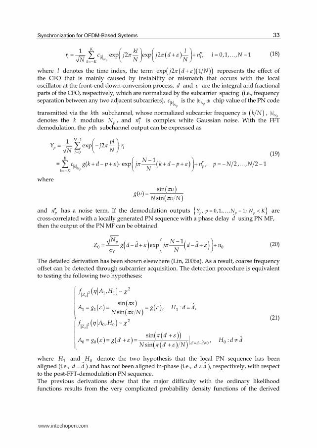
=−⎛ ⎞ ⎛ ⎞ ′′′= + + = −⎜ ⎟ ⎜ ⎟⎝ ⎠ ⎝ ⎠∑ … (18)
where l denotes the time index, the term ( )( )( )exp 2 1j d Nπ ε+ represents the effect of the CFO that is mainly caused by instability or mismatch that occurs with the local oscillator at the front-end down-conversion process, d and ε are the integral and fractional parts of the CFO, respectively, which are normalized by the subcarrier spacing (i.e., frequency separation between any two adjacent subcarriers),
Npkc is the thNp
k chip value of the PN code
transmitted via the thk subchannel, whose normalized subcarrier frequency is ( )k N , Npk
denotes the k modulus pN , and ln′′′ is complex white Gaussian noise. With the FFT demodulation, the thp subchannel output can be expressed as
( )1
0
1exp 2
1 = ( ) exp , 2 , , 2 1
Np
N
p ll
K
pkk K
plY j r
NN
Nc g k d p j k d p n p N N
N
πε π ε
−=
=−
⎛ ⎞= − ⋅⎜ ⎟⎝ ⎠−⎛ ⎞ ′′+ − + ⋅ + − + + = − −⎜ ⎟⎝ ⎠
∑∑ …
(19)
where
( )( )sin( )
sing
N N
πυυ πυ=
and pn′′ has a noise term. If the demodulation outputs { }, 0,1, , 1; p p pY p N N K= − <… are
cross-correlated with a locally generated PN sequence with a phase delay d̂ using PN MF, then the output of the PN MF can be obtained.
( ) ( )0 00
1ˆ ˆexppN N
Z g d d j d d nN
ε π εσ−⎛ ⎞= − + − + +⎜ ⎟⎝ ⎠ (20)
The detailed derivation has been shown elsewhere (Lin, 2006a). As a result, coarse frequency offset can be detected through subcarrier acquisition. The detection procedure is equivalent to testing the following two hypotheses:
( )( ) ( )( ) ( )
( )( ) ( ) ( )( )( )( )
2
2
21 1
1 1 1
20 0
ˆ0 0 00
,
sin ˆ, : , sin
,
sin ˆ, :sin
o
o
Z
Z
d d d
f A H
A g g H d dN N
f A H
dA g g d H d d
N d N
η χπεε επε
η χπ εε ε π ε ′= − ≠
⎧⎪⎪⎪ = = = =⎪⎪⎨⎪⎪ ′ +⎪ ′= = + = ≠⎪ ′ +⎪⎩
∼
∼ (21)
where 1H and 0H denote the two hypothesis that the local PN sequence has been
aligned (i.e., ˆd d= ) and has not been aligned in-phase (i.e., ˆd d≠ ), respectively, with respect
to the post-FFT-demodulation PN sequence. The previous derivations show that the major difficulty with the ordinary likelihood functions results from the very complicated probability density functions of the derived
www.intechopen.com
Recent Advances in Wireless Communications and Networks
34
random variable, ( )0 0A g ε= and ( )1 1A g ε= . Therefore, the two derived random variables
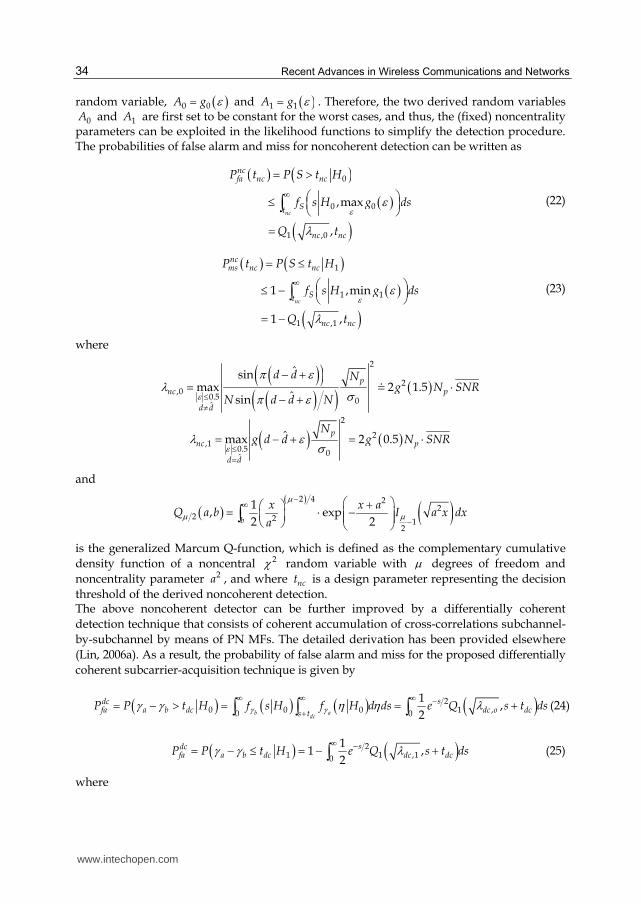
0A and 1A are first set to be constant for the worst cases, and thus, the (fixed) noncentrality parameters can be exploited in the likelihood functions to simplify the detection procedure. The probabilities of false alarm and miss for noncoherent detection can be written as
( ) ( )( )
( )0
0 0
1 ,0
,max
,
nc
ncfa nc nc
St
nc nc
P t P S t H
f s H g ds
Q t
ε ελ
∞= >
⎛ ⎞≤ ⎜ ⎟⎝ ⎠=∫ (22)
( ) ( )( )
( )1
1 1
1 ,1
1 ,min
1 ,
nc
ncms nc nc
St
nc nc
P t P S t H
f s H g ds
Q t
ε ελ
∞= ≤
⎛ ⎞≤ − ⎜ ⎟⎝ ⎠= −
∫ (23)
where
( )( )( )( ) ( )2
2,0
0.5 0ˆ
ˆsinmax 2 1.5
ˆsin
p
nc p
d d
d d Ng N SNR
N d d Nεπ ελ σπ ε≤
≠
− += ⋅− + 7
( ) ( )2
2,1
0.5 0ˆ
ˆmax 2 0.5p
nc p
d d
Ng d d g N SNRελ ε σ≤
== − + = ⋅
and
( ) ( ) ( )2 4 22
2 2 12
1, exp
2 2b
x x aQ a b I a x dx
a
μμ μ
−∞−
⎛ ⎞+⎛ ⎞= ⋅ −⎜ ⎟⎜ ⎟ ⎜ ⎟⎝ ⎠ ⎝ ⎠∫
is the generalized Marcum Q-function, which is defined as the complementary cumulative
density function of a noncentral 2χ random variable with μ degrees of freedom and
noncentrality parameter 2a , and where nct is a design parameter representing the decision
threshold of the derived noncoherent detection. The above noncoherent detector can be further improved by a differentially coherent
detection technique that consists of coherent accumulation of cross-correlations subchannel-
by-subchannel by means of PN MFs. The detailed derivation has been provided elsewhere
(Lin, 2006a). As a result, the probability of false alarm and miss for the proposed differentially
coherent subcarrier-acquisition technique is given by
( ) ( ) ( ) ( )20 0 0 1 ,0 0
1,
2b adc
sdcfa a b dc dc o dcs t
P P t H f s H f H d ds e Q s t dsγ γγ γ η η λ∞ ∞ ∞ −+= − > = = +∫ ∫ ∫ (24)
( ) ( )21 1 ,10
11 ,
2
sdcfa a b dc dc dcP P t H e Q s t dsγ γ λ∞ −= − ≤ = − +∫ (25)
where
www.intechopen.com
Synchronization for OFDM-Based Systems
35
( )( )
0
1
2 2,0
ˆ
2 2,1
ˆ
4 1.5
4 0.5
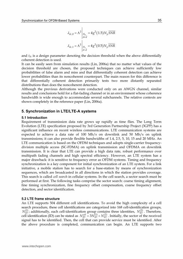
dc H pd d
dc H pd d
g N SNR
g N SNR
λ
λ≠
=
= Λ =
= Λ =
and tdc is a design parameter denoting the decision threshold when the above differentially coherent detection is used. It can be easily seen from simulation results (Lin, 2006a) that no matter what values of the decision threshold are chosen, the proposed techniques can achieve sufficiently low probabilities of false alarm and miss and that differentially coherent detection can achieve lower probabilities than its noncoherent counterpart. The main reason for this difference is that differentially coherent detection primarily tests two more distantly separated distributions than does the noncoherent detection. Although the previous derivations were conducted only on an AWGN channel, similar results and conclusions hold for a flat-fading channel or in an environment whose coherence bandwidth is wide enough to accommodate several subchannels. The relative contexts are shown completely in the reference paper (Lin, 2006a).
5. Synchronization in LTE/LTE-A systems
5.1 Introduction
Requirement of transmission data rate grows up rapidly as time flies. The Long Term Evolution (LTE) specification proposed by 3rd Generation Partnership Project (3GPP) has a significant influence on recent wireless communications. LTE communication systems are expected to achieve a data rate of 100 Mb/s on downlink and 50 Mb/s on uplink transmissions; it can also provide flexible bandwidths of 1.4, 2.5, 5, 10, 15 and 20 MHz. An LTE communication is based on the OFDM techniques and adopts single-carrier frequency-division multiple access (SC-FDMA) on uplink transmission and OFDMA on downlink transmission. It is clear that LTE can provide a high data rate, robust performance over multipath fading channels and high spectral efficiency. However, an LTE system has a major drawback: it is sensitive to frequency error as OFDM systems. Timing and frequency synchronization is a key component for initial synchronization of an LTE system. For a link initiative, a mobile station has to search for a base-station by means of synchronization sequences, which are broadcasted in all directions in which the station provides coverage. This search is called cell search in cellular systems. In the cell search, a sector search must be performed at first. The following tasks comprise the sector search: coarse timing alignment, fine timing synchronization, fine frequency offset compensation, coarse frequency offset detection, and sector identification.
5.2 LTE frame structure
An LTE supports 504 different cell identifications. To avoid the high complexity of a cell search procedure, these cell identifications are categorized into 168 cell-identification groups,
(1)IDN ; additionally, each cell-identification group contains three identities, (2)
IDN . Therefore, cell identification (ID) can be stated as (1) (2)3cell
ID ID IDN N N= + . Initially, the sector of the received signal has to be identified. Then, the cell that can provide service must be identified. After the above procedure is completed, communication can begin. An LTE supports two
www.intechopen.com
Recent Advances in Wireless Communications and Networks
36
synchronization signals for the cell search procedure. One is the primary synchronization signal (P-SCH), and the other is the secondary synchronization signal (S-SCH). P-SCH and S-SCH are inserted into the last two OFDM symbols in the first slot of the sub-frame zero and sub-frame five, where the frame structure is shown in Fig. 9. The P-SCH signal is transmitted twice in each 10-ms frame. It can provide frame timing synchronization with a tolerance of 5 ms. The main goal of the P-SCH is to conduct timing synchronization, coarse frequency-offset detection and sector identification. Each frame has a pair of S-SCH signals that can be chosen from the 168 different cell identifications. Therefore, the S-SCH signal is used to determine the cell ID.
Fig. 9. LTE frame structure
The frame structure of the LTE system is depicted in Fig. 9, and the length of each frame is 10 ms. Each frame is divided into ten 1-ms sub-frames. Each sub-frame contains two slots with lengths 0.5 ms. Additionally, each slot consists of seven symbols, and each symbol contains 2048 samples. The zeroth and fifth sub-frame convey P-SCH and S-SCH signals. According to the LTE specification, the CP length is 160 samples in the first symbol of a slot and 144 samples in the other 6 symbols of the slot. When the occupied bandwidth is 20 MHz, the system parameters are as follows: the sampling rate is 30.72 MHz, the FFT size is 2048, and the subcarrier spacing is 15 KHz. The synchronization signals occupy only the central 72 sub-carriers of the 2048 sub-carriers. Both boundaries of the band conveying the synchronization signals accommodate 5 null subcarriers. Therefore, the synchronization signals only adopt 62 subcarriers.
5.3 P-SCH signal
The number of physical-layer cell identifications is very large. To avoid high complexity in the cell search, the cell identifications are partitioned into three sets, physical-layer cell-identification group (2)
IDN or sector. The P-SCH signal is composed of three Zadoff-Chu (ZC)
www.intechopen.com
Synchronization for OFDM-Based Systems
37
sequences with lengths of 62 in the frequency domain. Each sequence represents a sector identification. The ZC sequences employed in the LTE (3GPP LTE, 2005) are written as
( 1)
63 , 0,1,....,30( )
( 1)( 2)
63 , 31,32,....,61.
u
un nj
e nd n
u n nj
e n
ππ
+⎧ −⎪ =⎪= ⎨ + +⎪ −⎪ =⎩ (26)
(2)IDN Root index u
0 25
1 29
2 34
Table 1. Root index u of sector identification (3GPP LTE, 2005)
where u is the root index for which values are set to 25, 29, and 34, which correspond to (2)IDN =0,1 or 2, respectively. A ZC sequence is a chirp-like sequence and is symmetric both in
the time domain and frequency domain. The sequence has good correlation properties. Therefore, the P-SCH signal employing the ZC sequence is utilized to help coarse timing synchronization and frequency-offset detection.
5.4 Cell search method Research regarding sector search in LTE systems has been studied extensively (Chen et al., 2009, Manolakis et al., 2009, Tsai et al., 2007). Three methods were studied previously (Tsai et al., 2007). They mainly take advantage of auto-correlation, cross-correlation and hybrid detection. The first method adopts auto-correlation to search for P-SCH location by taking advantage of the repetitions of P-SCH sequences. Coarse frequency-offset acquisition depends on the output of the auto-correlator. Its main advantage is low complexity, but the timing detection is inevitably distorted on signals with low SNR. The second method employs cross-correlation between the received signal and the locally-generated P-SCH to detect timing and frequency offset. Additionally, the cross-correlation can be divided into several segments to counter any effect caused by a high frequency offset. The method has a trustworthy timing detection, but its complexity is higher than auto-correlation detection. Hybrid detection combines advantages of auto-correlation and cross-correlation. Its complexity is less than that employing cross-correlation detection. The auto-correlation detection obtains coarse timing and frequency offset, and compensates for the frequency error. Then, the accurate timing can be obtained by exploiting cross-correlation.A previous study (Manolakis et al., 2009) used maximum likelihood (ML) criterion to estimate the fractional frequency offset and the OFDM symbol timing; its performance is improves by averaging 8 OFDM symbols. Next, cross-correlation between the three P-SCH sequences and the received signal is obtained; and the sector ID can be determined by selecting the highest cross-correlation according to the orthogonality among the used Zadoff-Chu sequences.
5.5 Carrier aggregation Carrier aggregation is one of the most important technologies in the new LTE-Advanced standards. This technique will also play a significant role for 4G communication systems. By
www.intechopen.com
Recent Advances in Wireless Communications and Networks
38
using carrier aggregation, a peak data rate up to 1 Gb/s is possible in future 4G mobile communications. Because of the flexibility of effective transmission, the user can exploit numerous carriers at the same time. In addition, these carriers may lie in the same or different band and may have different bandwidths. Carrier aggregation provides diverse combinations and flexible spectrum usability and has attracted attention. Carrier aggregation techniques can be classified into two categories: continuous and discontinuous as shown in Fig. 10. These two categories can be subdivided into three types: intraband contiguous, intraband discontinuous and interband. A diagram describes their difference in Fig. 11.
In this chapter, the authors intend to introduce the OFDM communication systems and take care of the main issue, frequency offset, can lead to severe performance degradation. Two classifications of synchronization techniques are introduced. Several novel techniques have been thoroughly discussed in great detail in this chapter. LTE/LTE-A systems have been chosen as candidates for 4G mobile communication. The concept of LTE-LTE-A systems is mentioned in the end of this chapter.
www.intechopen.com
Synchronization for OFDM-Based Systems
39
7. References
3GPP LTE (2005). TS 36.211 V8.3.0: Technical Specification Group Radio Access Network; Evolved Universal Terrestrial Radio Access (E-UTRA); Physical Channels and Modulation (Release 8)
Bolcskei, H. (2001). Blind estimation of symbol timing and carrier frequency offset in wireless OFDM systems, IEEE Transactions on Communications, Vol.49, No.6, (June 2001), pp.988-999
Chen, Y., Wen, X., Zheng, W. & Lin, X. (2009). Symbol timing estimation and sector detection algorithm based on LTE TDD system, Proceedings of IEEE Network Infrastructure and Digital Content Conference, 2009 (IC-NIDC 2009), Beijing, China, pp.828-832.
Classen, F. & Meyr, H. (1994). Frequency synchronization algorithms for OFDM systems suitable for communication over frequency selective fading channels, Proceedings of IEEE Vehicular Technology Conference, 1994 (VTC’94), Stockholm, Sweden, pp. 1655-1659
Daffara, F. & Chouly, A. (1993). Maximum likelihood frequency detectors for orthogonal multicarrier systems, Proceedings of IEEE Communications Conference, 1993 (ICC’93), Geneva, Switzerland, pp. 766-771
Daffara, F. & Adami, O. (1995). A new frequency detector for orthogonal multicarrier transmission techniques, Proceedings of IEEE Vehicular Technology Conference, 1995 (VTC’95), Chicago, USA, pp. 804-809
Dahlman, E., Parkvall, S., Skold, J. & Beming, P. (2007) 3G Evolution HSPA and LTE for Mobile Broadband, Academic Press
Iwamura, M., Etemad, K., Fong M.-H., Nory, R. & Love, R. (2010) Carrier aggregation framework in 3GPP LTE-advanced [WiMAX/LTE update], IEEE Communications Magazine, Vol.48, No.8, (August 2010), pp.66-67
Jakes, W. C. & Cox, D. C. (1994). Microwave Mobile Communications. Wiley-IEEE Press Kapoor, S., Marchok, D. J. & Huang, Y.-F. (1998). Pilot assisted synchronization for wireless
OFDM systems over fast time varying fading channels, Proceedings of IEEE Vehicular Technology Conference, 1998 (VTC’98), Ottawa, Canada, pp. 2077-2080
Lin, J.-C. (2002a). Noncoherent sequential PN code acquisition using sliding correlation for chip-asynchronous DS/SS, IEEE Transactions on Communications, Vol.50, No.4, (April 2002), pp.664-676
Lin, J.-C. (2002b). Differentially coherent PN code acquisition with full-period correlation in chip-asynchronous DS/SS receivers, IEEE Transactions on Communications, Vol.50, No.5, (May 2002), pp.698-702
Lin, J.-C. (2002c). Differentially coherent PN code acquisition based on a matched filter for chip-asynchronous DS/SS communications, IEEE Transactions on Vehicular Technology, Vol,51, No.6, (November 2002), pp.1596-1599
Lin, J.-C. (2003). Maximum-likelihood frame timing instant and frequency offset estimation for OFDM communication over a fast Rayleigh-fading channel, IEEE Transactions on Vehicular Technology, Vol,52, No.4, (July 2003), pp.1049-1062
Lin, J.-C. (2004). Frequency offset estimation by differentially coherent frequency error characterization for OFDM wireless communications, Proceedings of IEEE Communications Conference, 2004 (ICC’04), Paris, France, pp. 2387-2391.
Lin, J.-C. (2005). Frequency offset acquisition based on subcarrier differential detection for OFDM communications on doubly-selective fading channel, Proceedings of IEEE Communications Conference, 2005 (ICC’05), Seoul, Korea, pp. 1952-1956.
www.intechopen.com
Recent Advances in Wireless Communications and Networks
40
Lin, J.-C. (2006a). Coarse frequency-offset acquisition via subcarrier differential detection for OFDM communications, IEEE Transactions on Communications, Vol.54, No.8, (August 2006), pp.1415-1426
Lin, J.-C. (2006b). Frequency offset estimation technique based on error characterization for OFDM communications on time-varying multipath fading channels, Proceedings of IEEE Communications Conference, 2006 (ICC’06), Istanbul, Turkey, pp.2911-2916.
Lin, J.-C. (2007). A frequency offset estimation technique based on frequency error characterization for OFDM communications on multipath fading channels, IEEE Transactions on Vehicular Technology, Vol,56, No.3, (May 2007), pp.1209-1222
Luise, M. & Reggiannini, R. (1996). Carrier frequency acquisition and tracking for OFDM systems, IEEE Transactions on Communications, Vol.44, No.11, (November 1996), pp.1590-1598
Lv, T., Li, H. & Chen, J. (2005) Joint estimation of symbol timing and carrier frequency offset of OFDM signals over fast time-varying multipath channels, IEEE Transaction on Signal Processing, Vol.53, No.12, (December 2005), pp.4526-4535
Manolakis, K., Gutierrez Estevez, D. M., Jungnickel, J., Xu, W. & Drewes, C. (2009) A closed concept for synchronization and cell Search in 3GPP LTE systems, Proceedings of IEEE Wireless Communications and Networking Conference, 2009 (WCNC 2009), Budapest, Hungary, pp. 1-6.
Moose, P. H. (1994). A technique for orthogonal frequency division multiplexing frequency offset correction, IEEE Transactions on Communications, Vol.42, No.10, (October 1994), pp.2908-2914
Nee, V. R. & Prasad, R., (2000). OFDM for Wireless Multimedia Communications, Artench House Okada, M., Hara, S., Komaki, S. & Morinaga, N. (1996). Optimum synchronization of
orthogonal multi-carrier modulated signals, Proceedings of IEEE Personal, Indoor and Mobile Radio Communications Conference, 1996 (PIMRC’96), Taipei, Taiwan, pp. 863-867
Park, B., Ko, E., Cheon, H., Kang, C. & Hong, D. (2001). A Blind OFDM synchronization algorithm based on cyclic correlation, IEEE Signal Processing Letters, Vol.11, No.2, (February 2004), pp.83-85.
Popovic, B. M. (1992). Generalized chirp-like polyphase sequences with optimum correlation properties, IEEE Transactions on Information Theory, Vol.38, No.4, (July 1992), pp.1406-1409
Van de Beek, J.-J., Sandell, M. & Borjesson, P. O. (1997). ML estimation of time and frequency offset in OFDM systems, IEEE Transaction on Signal Processing, Vol.45, No.7, (July 1997), pp. 1800-1805
Tsai, Y., Zhang, G., Grieco, D. & Ozluturk, F. (2007). Cell searrch in 3GPP Long Term Evolution systems, IEEE Vehicular Technology Magazine, Vol.2, No.2, (June 2007), pp.23-29
Warner, W. D. & Leung, C. (1993). OFDM/FM frame synchronization for mobile radio data communications, IEEE Transactions on Vehicular Technology, Vol,42, No.3, (August 1993), pp.302-313
Yuan, G., Zhang, X., Wang, W. & Yang, Y. (2010). Carrier Aggregation for LTE-advanced mobile communication systems, IEEE Transaction on Communication Magazine, Vol.48, No.2, (February 2010), pp.88-93
www.intechopen.com
Recent Advances in Wireless Communications and NetworksEdited by Prof. Jia-Chin Lin
ISBN 978-953-307-274-6Hard cover, 454 pagesPublisher InTechPublished online 23, August, 2011Published in print edition August, 2011
InTech ChinaUnit 405, Office Block, Hotel Equatorial Shanghai No.65, Yan An Road (West), Shanghai, 200040, China
Phone: +86-21-62489820 Fax: +86-21-62489821
This book focuses on the current hottest issues from the lowest layers to the upper layers of wirelesscommunication networks and provides “real-time†research progress on these issues. The authors havemade every effort to systematically organize the information on these topics to make it easily accessible toreaders of any level. This book also maintains the balance between current research results and theirtheoretical support. In this book, a variety of novel techniques in wireless communications and networks areinvestigated. The authors attempt to present these topics in detail. Insightful and reader-friendly descriptionsare presented to nourish readers of any level, from practicing and knowledgeable communication engineers tobeginning or professional researchers. All interested readers can easily find noteworthy materials in muchgreater detail than in previous publications and in the references cited in these chapters.
How to referenceIn order to correctly reference this scholarly work, feel free to copy and paste the following:
Yu-Ting Sun and Jia-Chin Lin (2011). Synchronization for OFDM-Based Systems, Recent Advances inWireless Communications and Networks, Prof. Jia-Chin Lin (Ed.), ISBN: 978-953-307-274-6, InTech, Availablefrom: http://www.intechopen.com/books/recent-advances-in-wireless-communications-and-networks/synchronization-for-ofdm-based-systems


![Coherent Detection of Turbo-Coded OFDM Signals … · an OFDM frame when it is not present) ... synchronization for OFDM are given in [15]– ... Detection of OFDM signals, ...](https://static.documents.pub/doc/80x56/5ae5fd777f8b9a08778c6dfc/coherent-detection-of-turbo-coded-ofdm-signals-ofdm-frame-when-it-is-not-present.jpg)


