Comparative Study of various standards-based Synchronization solutions Manas Mandal, Juniper Networks Priya M, Juniper Networks August 16, 2010 Abstract Synchronization is a problem in communication systems where electronic devices deal with the idea that the internal clocks of several such devices may differ, due to clock drift. There are several problems that occur as a repercussion of this and several solutions, some being more appropriate than others in certain contexts. Synchronization today is gaining lot of industry attention in communication systems because of new increased levels of accuracy, speed, inter- operability requirements and hence the problems in synchronization are being revisited by new standards. In a centralized system the solution is trivial; the centralized server will dictate the system time. In a distributed system the problem takes on more complexity because a global time is not easily known. For ‘data’ only networks, synchronized clocking of the network is not necessary. However, when an ATM or any packet-based network is used to support Circuit Emulation Services (CES), or voice in general it becomes necessary to provide a means of providing a synchronized data path. Moreover different applications require synchronization at different precision levels. The most used clock synchronization solution on the Internet is the Network Time Protocol (NTP) which is a layered client-server architecture based on UDP message passing. But NTP cannot meet the precision requirements of extremely time-sensitive applications like 2G/3G. Synchronization is a problem in existing PDH networks as well. The traditional mobile back haul networks are TDM-based and are hence inherently synchronous in nature. As mobile back haul networks are rapidly transitioning IP/MPLS networks with Ethernet as the transport medium, there is an increasing need for SONET/SDH-like frequency synchronization capability. Numerous methods have been suggested for augmenting Ethernet to distribute frequency and/or timing information, such as IEEE’s 1588, IETF’s NTP, and methods developed for use of TDM pseudo wires. There is yet another method for transport of synchronization over Ethernet networks, called Synchronous Ethernet (Sync-E), that locks the timing of the Ethernet physical layer, much the same way that SONET/SDH does. This paper explores the various standards-based solutions that address the synchronization problem for various applications, with a note on the challenges overcome and limitations of each of these solutions. A comparative study of the complexity involved in clock recovery, performance, achievable precision parameters, cost and scalability of the various synchronization schemes is presented. 1
Transcript
Comparative Study of various standards-based
Synchronization solutions
Manas Mandal, Juniper NetworksPriya M, Juniper Networks
August 16, 2010
Abstract
Synchronization is a problem in communication systems where electronic devices deal withthe idea that the internal clocks of several such devices may differ, due to clock drift. Thereare several problems that occur as a repercussion of this and several solutions, some being moreappropriate than others in certain contexts. Synchronization today is gaining lot of industryattention in communication systems because of new increased levels of accuracy, speed, inter-operability requirements and hence the problems in synchronization are being revisited by newstandards.
In a centralized system the solution is trivial; the centralized server will dictate the systemtime. In a distributed system the problem takes on more complexity because a global time is noteasily known. For ‘data’ only networks, synchronized clocking of the network is not necessary.However, when an ATM or any packet-based network is used to support Circuit EmulationServices (CES), or voice in general it becomes necessary to provide a means of providing asynchronized data path. Moreover different applications require synchronization at differentprecision levels.
The most used clock synchronization solution on the Internet is the Network Time Protocol(NTP) which is a layered client-server architecture based on UDP message passing. But NTPcannot meet the precision requirements of extremely time-sensitive applications like 2G/3G.Synchronization is a problem in existing PDH networks as well. The traditional mobile backhaul networks are TDM-based and are hence inherently synchronous in nature. As mobileback haul networks are rapidly transitioning IP/MPLS networks with Ethernet as the transportmedium, there is an increasing need for SONET/SDH-like frequency synchronization capability.Numerous methods have been suggested for augmenting Ethernet to distribute frequency and/ortiming information, such as IEEE’s 1588, IETF’s NTP, and methods developed for use of TDMpseudo wires. There is yet another method for transport of synchronization over Ethernetnetworks, called Synchronous Ethernet (Sync-E), that locks the timing of the Ethernet physicallayer, much the same way that SONET/SDH does.
This paper explores the various standards-based solutions that address the synchronizationproblem for various applications, with a note on the challenges overcome and limitations ofeach of these solutions. A comparative study of the complexity involved in clock recovery,performance, achievable precision parameters, cost and scalability of the various synchronizationschemes is presented.
1
Standards-based Synchronization solutions
Contents
1 The Synchronization problem 4
2 Synchronization requirements for various Mobile technologies 5
The problem of synchronization is not new to communication engineers and is a well understoodtopic in general; however it is finding new directions as applications demanding it are increasing innumber with stringent accuracy and precision requirements. In this section we try to explain theproblem in general so that one can appreciate the solutions presented by the various standards.
The problem revolves around three factors A) Time B) Phase and C) Frequency. In principle,frequency can be derived from time and distributing time synchronization is one way of achievingphase synchronization too.
Data in telecommunication network is pumped at a constant rate from the source and if the endreceiver or intermediate nodes are not able to keep up the same rate then receiver’s buffers will eitherslip or overrun resulting in data loss which causes undesired effects in the communication. Dataloss during a voice call merely causes some inconvenience such as some audible clicks in the voice,however the problem gets much more exaggerated when it affects data traffic causing retransmissionand lost connections. Similarly in mobile communication involving radio links, frequency inaccuracycan cause mobile calls to disconnect or experience bad handoffs when moving from one cell siteto another. Besides in CDMA and UMTS TDD mobile networks if phase is inaccurate then overtime one base station will overrun into another base station’s timeslot causing undesired inter-cellinterference[18].
So if all the clocks in the network nodes were accurate such that they can maintain a constantfrequency and phase then we would never get into this problem. But in reality all clocks drift fromtheir original frequency and phase over time in a non-deterministic way due to various physicalfactors and ambient conditions, particularly temperature. Accuracy of a clock is thus related tothis drift; slower the drift better the clock is. But unfortunately clocks with higher accuracy arevery high in cost like cesium based atomic clocks and it is not economical to have such clocks ateach and every network node. Typically this is solved by synchronizing the system clocks in eachnetwork node to a common reference clock such as an atomic clock. This can be done by two possibleapproaches[21]:
• Keeping synchronization at physical layer
• Use of packet based synchronization
Traditional networks such as SONET/SDH are inherently synchronized by design, using the firstoption. SyncE provides frequency synchronization over the physical layer in Ethernet networks. InPSNs, packet based synchronization usually involves distribution of time and frequency over thenetwork; however for accuracy, the synchronization mechanism needs to overcome various challengesof PSN such as:
• Packet delay variance
• Packet loss
• Packet re-ordering
• Queuing delays
IEEE1588v2 (PTP) and NTP are the major protocols in PSNs that try to use the second approachwhich are described in following sections of this paper.
Figure 1: Timing and Frequency requirements for various Mobile Technologies
2 Synchronization requirements for various Mobile technolo-gies
Synchronization has gained significant industry attention with telecommunication operators mov-ing from legacy time division multiplexing (TDM) based networks to packet switched networks(PSN). Operators are looking for optimal solutions to synchronization in terms of capital expen-diture (CAPEX) and operational expenditure (OPEX). Synchronization in PSN basically involvesdistribution of time and frequency in a network so that each node in the network has same senseof time and frequency. Synchronization problem is further stretched by the high precision requiredwhen it comes to backhauling various new mobile technologies such as LTE which are being deployedby the operators in the current date. Besides that deployment configurations and management imple-mentation needs to be carefully studied and considered for coming up with synchronization solutionsover a PSN. In order to meet these requirements various standardization bodies such as IEEE, IETFand ITU-T have defined their protocols.
Synchronization is a crucial factor in any kind of communication but in mobile communicationthe synchronization requirements are far more stretched by the kind of accuracy and precision that itrequires. Backhauling of these networks over PSNs is probably one of the most challenging jobs thatwe are facing today. Figure 1 shows clock accuracy requirements of various mobile technologies[19]that are being deployed at present day. The cellular base stations of mobile technologies require suchhighly accurate reference frequency as they derive the transmission frequencies from this and anydeviation from these would result in poor quality of service. In CDMA mobile network to achievethese stringent requirements operators were deploying GPS to provide accurate frequency to theCDMA BTSs. GPS also provided an accurate time phase reference required for CDMA. In case ofGSM/UMTS mobile networks operators were deriving the time from TDM (SONET/SDH/PDH)networks to time their BTS nodes.
All these seemed to work well as long as there was no need to transition from TDM to PSNfor backhauling the mobile traffic. In recent times transitioning from TDM to PSN has becomeimportant for operators to remain profitable in the business primarily because of two key factors[23]:
1. Revenue from growth in mobile users will not be able to balance the cost required to back-
haul the exponential increase in bandwidth required due to various video and multimediaapplications of mobile users.
2. Cost required to backhaul multiple mobile technologies using traditional TDM network is veryhigh for the operators.
This brings in a challenging situation where we need synchronization in an asynchronous PSNnetwork. In this context while moving from TDM based networks to PSNs the reference frequencyis lost and to address this circuit emulation services (CES) comes to provide some solution. CESis a generic term used for transport of services which can emulate TDM, ATM, MPLS, etc. Formobile backhaul CES needs to support TDM over IP which are defined by SATOP and CESOPstandards which is out of scope of this paper. However the performance of CES strongly dependson the underlying frequency distribution technique in the PSN which is what we are interested inthis paper.
Given below are the various scenarios when operators migrate from legacy networks to Ethernetbased networks for the mobile backhaul[20].
In one scenario, both BS and RAN NC in the mobile core do not have native Ethernet interfacesupport and so cannot be directly connected to the Carrier Ethernet network. An interworkingcapability is required to be able to connect the TDM/ATM interfaces on the BS and NC to theEthernet network. This scenario mainly pertains to the migration step where both legacy andEthernet technologies need to be supported.
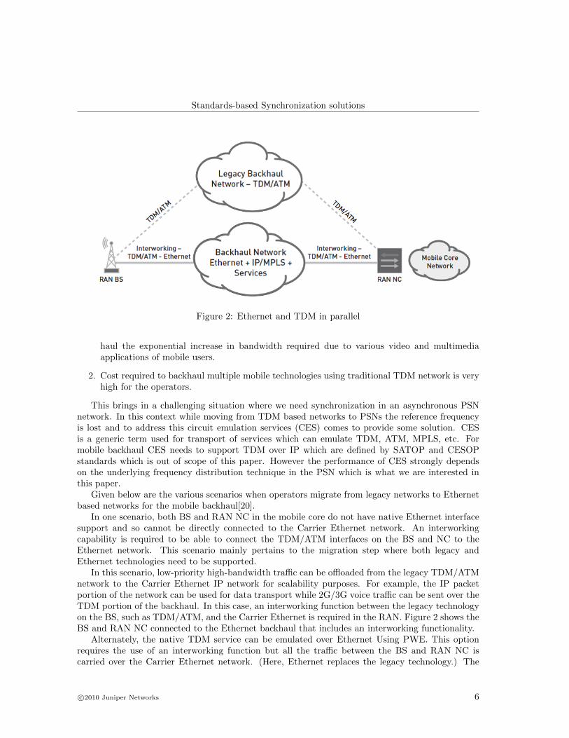
In this scenario, low-priority high-bandwidth traffic can be offloaded from the legacy TDM/ATMnetwork to the Carrier Ethernet IP network for scalability purposes. For example, the IP packetportion of the network can be used for data transport while 2G/3G voice traffic can be sent over theTDM portion of the backhaul. In this case, an interworking function between the legacy technologyon the BS, such as TDM/ATM, and the Carrier Ethernet is required in the RAN. Figure 2 shows theBS and RAN NC connected to the Ethernet backhaul that includes an interworking functionality.
Alternately, the native TDM service can be emulated over Ethernet Using PWE. This optionrequires the use of an interworking function but all the traffic between the BS and RAN NC iscarried over the Carrier Ethernet network. (Here, Ethernet replaces the legacy technology.) The
Figure 4: Legacy Network in parallel with Ethernet
native TDM/ATM service can be carried over Ethernet using pseudowires for circuit emulation.Figure 3 shows a logical representation of the TDM/ATM traffic and Ethernet traffic being carriedover the Ethernet backhaul.
In another scenario, the BS and RAN NC are capable of supporting both Ethernet and thelegacy technology. This leads to the options of either using the legacy network in conjunction withEthernet or just the latter as shown in Figures 4 and 5 respectively.
The internetworking capability that is required to connect the TDM/ATM interfaces on theBS and NC to the Ethernet network needs to be able to pass on the timing information over theinherently asynchronous Ethernet network too. There are various standards defined for transferof timing information over packet based networks. Some require synchronization capable hardwareand some solutions are packet based; some solutions offer only frequency synchronization while otheroffer time and phase synchronization too. We will look at the standards and their application in themobile backhaul space in the coming sections.
3 Dominant Standards and their comparisons
In this section we will look at the dominant synchronization standards over PSNs and draw somecomparisons based on their strengths and weaknesses. NTP and IEEE1588v2 provide packet/mes-sage based solutions where a master-slave relation is created among the network nodes and masterdistributes the timing to its slaves using packets that carry timestamps in it. The master usually
Figure 5: Base station to Mobile core via an IP network
has access to a very accurate reference of timing such as GPS. Then there is SyncE technique basedon ITU-T Recommendations G.8261, G.8262 and G.8264, which works at physical layer much likelegacy SONET/SDH.
3.1 IEEE 1588v2 / PTP
IEEE1588 is also commonly known as Precision Time Protocol (PTP) was originally designed[9][8]for critical industrial automation applications which require precise timing. Today PTP provideshighest level of frequency accuracy and timing precision among message based synchronization stan-dards. Synchronization in PTP is achieved in a two step process:
Step 1: The protocol constructs a Master-Slave hierarchy of clocks in the network using a dis-tributed algorithm called Best Master Clock (BMC).
Step 2: Synchronize each Slave clock to its Master Clock.
3.1.1 Synchronization
In order to understand the basic synchronization technique in PTP it is desirable to know the basicmessage flow in PTP. Figure 6[8] shows various PTP messages used to synchronize the Slave Clockto its Master.
This involves exchange of three main messages Sync message, DelayRequest message andDelayResponse message. Follow Up message is optional and used to ease the use of PTPv2 hard-ware implementation. The message exchange pattern is as follows:
1. The master sends a Sync message to the slave and notes time t1 at which it was sent.
2. The slave receives the Sync message and notes the time of reception t2.
3. The master conveys to the slave the timestamp t1 by either of the following way:
(a) Embedding the timestamp t1 in the Sync message, but this requires some sort of hardwareprocessing for highest accuracy and precision.
(b) Embedding the timestamp in a Follow up message.
4. The slave sends a Delay Req message to the master and notes the time t3 at which it wassent.
5. The master receives the Delay Req message and notes the time of reception t4.
6. The master conveys to the slave the timestamp t4 by embedding it in a Delay Resp message.
After this exchange of messages slave will compute the offset of slave clock from master in thefollowing way:
MS diff = t2 − t1 (1)
MS diff = Offset + MS delay (2)
where MS delay is Master to Slave path delay
SM diff = t4 − t3 (3)
SM diff = −Offset + SM delay (4)
where SM delay is Slave to Master path delayNow there are three unknowns:
• Offset
• MS delay
• SM delay
It is impossible to solve the above mathematical problem and compute the Offset. So to simplifyPTPv2 assumes symmetric path delay, where:
SM delay = MS delay (5)
and computes Offset as follows:
Offset =[(t2 − t1) − (t4 − t3)]
2(6)
However symmetric delay in PSNs is almost never a reality and PTP version 2 tries to addressesthis by introduction of Transparent Clocks which take into account the delay asymmetry driven bynetwork element queuing and scheduling.
3.1.2 Syntonization
Syntonization of clock deals with frequency synchronization of clocks in a PTP domain. As perspecification of PTPv2, within a domain any clock with a port in the SLAVE state, and any trans-parent clock, should syntonize to the grandmaster. The PTP standard specifies a way to performthis by using successive Sync messages (with their optional follow-up messages) however it does notrestrict users to use any other method. For example in some networks SyncE may provide frequencysynchronization or there may exist other physical signals accessible to clock that can be used tosyntonize the two clocks. In case using other methods than specified in the standard one must takecare to match the synchronization hierarchy established by BMC algorithm.
PTP specifies the following steps to syntonize the clock:
1. At the reception of Sync message the slave clock records a time-stamp.
2. For each Sync message received the Slave computes a correctedMasterEventT imestamp asfollows:
where, originT imestamp is the value of originT imestamp field of the Sync message (sendingtime stamp inserted by master while transmitting the Sync message). correctioF ield is thevalue of correction field in the Sync message. This field is fed by end-to-end transparent clocksand/or peer-to-peer transparent clocks located along the master-slave path. meanPathDelayis the mean value of successive estimated delay as follows:
[(t2 − t1) + (t4 − t3)]
2(8)
3. Frequency of the slave clock can be adjusted by using the following ratio:
(9)where N and N + 1 are the two consecutive sync messages.
3.1.3 PTP Device Categories
PTP categorizes devices in a PTP network into five main types namely:
1. Ordinary Clock
2. Boundary Clock
3. End-to-End transparent Clock
4. Peer-to-peer transparent Clock
5. Management nodes
Ordinary Clocks are single PTP port devices that maintains single PTP state machine and itcan be either a grandmaster clock described later in this section or a slave clock in a master-slavehierarchy.
Boundary Clocks represent multi-port devices in a PTP network where all the ports are synchro-nized to the local clock except the slave port which is chosen as reference (based on BMC algorithm)to lock the local clock. Boundary clocks demarcates multiple clock domains by terminating thePTP messages related to synchronization, establishing master-slave hierarchy and signaling in itsown protocol engine and not forwarding these to other ports. Boundary clocks also help to reducelarge latency variations in routers and switching devices in a network.
Transparent clocks came into existence in 2008 when version 2[8] of PTP was released in order toaddress the issue of path delay asymmetry in network discussed later in this section. These devicesare also multi-port devices in network just like boundary clocks but they forward all PTP messagesjust as a normal bridge, router or repeater. However for PTP event messages it calculates residencetime within the device and adds to a special field in the event messages introduced in version 2 ofPTP called correction field. In the peer-to-peer transparent clock peer-to-peer link delay of eachport in the device is measured and ingress port’s link delay is added to the correction field in theincoming message in addition to the residence time in the device. Besides this unlike end-to-endtransparent clocks, peer-to-peer transparent clock only forwards and corrects Sync and follow−upmessages. This is depicted in Figure 7[8].
Even though transparent clocks got introduced in the version 2 of PTP but use of transparentclock in the whole of network is limited as it has severe implication in terms of CAPEX and a carefuland balanced decision is needed.
Each PTP port of ordinary and boundary clock maintains an independent protocol state machine.Each port has a state associated with it which is used in determining master-slave hierarchy:
• MASTER: The port is the source of time on the path served by the port.
• SLAVE: The port synchronizes to the device on the path with port that is in MASTER state.
• PASSIVE: The port is not the master in the path nor does it synchronize to master.
The BMC algorithm has two parts:
1. Data set comparison algorithm
2. State decision algorithm
An instance of this algorithm is run at each clock. The first part of the algorithm results in gettinghighest quality clock by doing a pair-wise comparison of clock’s features called “data set”. The dataset is formed by receiving announce messages of various clocks in the network. Multicast or unicastpackets can be used to publish the announce message to all clocks in a network and care should betaken to avoid cyclic paths in the network which is usually done by running Spanning Tree Protocol.The highest ranking clock in a PTP domain is called Grandmaster clock to which all the slave clocksare synchronized. In the second part of the algorithm state of the port is decided based on resultsof the data set comparison algorithm.
3.1.5 Hardware assisted time-stamping of PTPv2 message
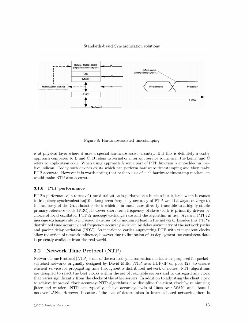
It is very hard to precisely timestamp a receipt or transmission of a message. PTP specifies variousplaces (A, B, C) where the timestamp can be done as depicted in Figure 8[8].
The accuracy of timestamp will better depending on how close in time from receipt or transmis-sion of the message it was done. So in Figure 8 points to the best message timestamp point which
is at physical layer where it uses a special hardware assist circuitry. But this is definitely a costlyapproach compared to B and C. B refers to kernel or interrupt service routines in the kernel and Crefers to application code. When using approach A some part of PTP function is embedded in low-level silicon. Today such devices exists which can perform hardware timestamping and they makePTP accurate. However it is worth noting that perhaps use of such hardware timestamp mechanismwould make NTP also accurate.
3.1.6 PTP performance
PTP’s performance in terms of time distribution is perhaps best in class but it lacks when it comesto frequency synchronization[10]. Long-term frequency accuracy of PTP would always converge tothe accuracy of the Grandmaster clock which is in most cases directly traceable to a highly stableprimary reference clock (PRC), however short-term frequency of slave clock is primarily driven bychoice of local oscillator, PTPv2 message exchange rate and the algorithm in use. Again if PTPv2message exchange rate is increased it causes lot of undesired load in the network. Besides this PTP’sdistributed time accuracy and frequency accuracy is driven by delay asymmetry of the network pathsand packet delay variation (PDV). As mentioned earlier augmenting PTP with transparent clocksallow reduction of network influence, however due to limitation of its deployment, no consistent datais presently available from the real world.
3.2 Network Time Protocol (NTP)
Network Time Protocol (NTP) is one of the earliest synchronization mechanisms proposed for packet-switched networks originally designed by David Mills. NTP uses UDP/IP on port 123, to ensureefficient service for propagating time throughout a distributed network of nodes. NTP algorithmsare designed to select the best clocks within the set of reachable servers and to disregard any clockthat varies significantly from the clocks of the other servers. In addition to adjusting the client clockto achieve improved clock accuracy, NTP algorithms also discipline the client clock by minimizingjitter and wander. NTP can typically achieve accuracy levels of 10ms over WANs and about 1ms over LANs. However, because of the lack of determinism in Internet-based networks, there is
no worst-case accuracy guarantee. NTP v3 is the latest released version which runs very stableon many operating systems. NTP v4[11] has some enhancements over v3 and has better supportfor some operating systems. RFC 1305 specifies the NTPv3 protocol and RFC 5905 specifies theNTPv4. Additionally, there’s also a simplified version of the protocol called SNTP (Simple NetworkTime Protocol). SNTP[12] uses the same TCP/IP packet structure like NTP but due to the simpleralgorithms, it provides only very reduced precision.
3.2.1 NTP Architecture
NTP uses a hierarchical, semi-layered system of levels of clock sources. Each level of this hierarchyis termed a stratum and is assigned a layer number starting with 0 (zero) at the top. The stratumlevel defines its distance from the reference clock and exists to prevent cyclical dependencies in thehierarchy. Figure 9[13] shows a simplified example of an NTP topology with 4 Stratum Levels (inaddition to a Reference Time Source Stratum Level)
NTP servers operating in the same stratum may be associated with others in a peer to peerbasis, so they may decide who has the higher quality of time and then can synchronize to the mostaccurate. In addition to the client-server model and the peer to peer model, a server may broadcasttime to a broadcast or multicast IP addresses and clients may be configured to synchronize to thesebroadcast time signals. NTP uses UTC as reference time. On Unix-based systems, the NTP packagecontains a background program called ntpd which synchronizes the computer’s system time to oneor more external reference time sources which can be either other devices on the network, or a radioclock which is connected to the computer. Because of sensitivity to timing, however, it is important
to have the standard NTP clock phase-locked loop implemented in kernel space. Once the NTPdaemon is up and running, it will operate by exchanging packets (time and sanity check exchanges)with its configured servers at poll intervals and its behavior will depend on the delay between thelocal time and its reference servers. Basically, the process starts when the NTP client sends a packetcontaining its timestamp to a server. When the server receives such a packet, it will in turn storeits own timestamp and a transmit timestamp into the packet and send it back to the client. Whenthe client receives the packet it will log its receipt time in order to estimate the traveling time of thepacket. The packet exchange takes place until a NTP server is accepted as a synchronization source,which take about five minutes. The NTP daemon tries to adjust the clock in small steps and willcontinue until the client gets the accurate time. If the delay between both the server and client isbig enough the daemon will terminate and the time would need to be adjusted manually and startthe daemon again.
3.2.2 NTP - Advantages and Limitations
• NTP is highly scalable: A synchronization network may consist of several reference clocks.Each node of such a network can exchange time information either bidirectional or unidirec-tional. Propagating time from one node to another, forms a hierarchical graph with referenceclocks at the top.
• Having available several time sources, NTP can select the best candidates to build its estimateof the current time. The protocol is highly accurate, using a resolution of less than a nanosecond(about 2−32 seconds).
• Even when a network connection is temporarily unavailable, NTP can use measurements fromthe past to estimate current time and error.
• NTP is relatively inexpensive to implement requiring very little hardware.
• The hierarchical organization and distribution of time information reduces the protocol over-head, and allows selected hosts to be equipped with cheaper by less accurate clocks. NTPprovides information which organizes this hierarchy on the basis of precision or estimated er-ror. NTP messages are generally sent regardless of the reach ability state or stratum (rank)of the peers.
• There is no provision in NTP for peer discovery or acquisition.
• By its very nature clock synchronization requires long periods of time (hours or days) andmultiple comparisons in order to maintain accurate timekeeping. The more comparisons per-formed, the greater the accuracy of the timekeeping.
• NTP requires manual configuration of the devices with which a node should form an associa-tion. In LANs, broadcasting NTP messages reduces configuration complexity; however it alsomarginally compromises timekeeping accuracy.
• The accuracy can degrade substantially if networks become congested. For precise timingapplications, there is no allowance to account for network delays other than through multiplepoll time averaging techniques and buffering. So NTP, even in the latest implementation doesnot meet the higher precision requirements for 3G/4G wireless backhaul.
Real-time transport protocol (RTP)[14] provides end-to-end delivery services for data with real-timecharacteristics, such as interactive audio and video. Those services include payload type identifica-tion, sequence numbering, time stamping and delivery monitoring. Applications typically run RTPon top of UDP to make use of its multiplexing and checksum services, but RTP maybe used withother suitable underlying network or transport protocols. RTP consists of two closely-linked parts:
• The real-time transport protocol (RTP), to carry data that has real-time properties
• The RTP control protocol (RTCP), to monitor the quality of service to convey informationabout the participants in an on-going session.
As a part of the control signaling in RTCP, wallclock time (absolute date and time) is representedusing the timestamp format of the Network Time Protocol (NTP). An implementation is not requiredto run the Network Time Protocol in order to use RTP. However, running NTP may be useful forsynchronizing streams transmitted from separate hosts. Inter-media synchronization also requiresthe NTP and RTP timestamps included in the RTCP packets. The audio and video may even betransmitted by different hosts if the reference clocks on the two hosts are synchronized by somemeans such as NTP. A receiver can then synchronize presentation of the audio and video packets byrelating their RTP timestamps using the timestamp pairs in RTCP sender packets. Typical usagescenarios for RTP include:
• Simple multicast audio conference
• Audio and video conference - If both audio and video are used in a conference, they aretransmitted as separate RTP sessions. Despite the separation, synchronized playback of asource’s audio and video can be achieved using timing information carried in the RTCP packetsfor both sessions.
RTP and RTCP provide native mechanism for the transport of real-time data as well as theflexibility of adding application-specific functionalities. Thus with some enhancements, RTP is apreferred synchronization solution[22] in some CES networks, since it can guarantee precision levelsof NTP. It is widely used for IP-based video conferencing systems. The NTP timestamps in thesender’s report are assumed to be synchronized between all media senders within a single session.If the media sources come from the same network source, this is obviously not an issue. Receiverssynchronize to the sender, the only solution feasible for multicast. Experience has shown that allother cross-media, cross-host schemes end up doing clock synchronization, usually inferior to NTPand application-specific.
3.4 Synchronous Ethernet (Sync-E)
Synchronous Ethernet (Sync-E) is one way to achieve frequency synchronization over Ethernet.SyncE uses the physical layer interface to pass timing information from node to node, in the sameway timing is passed in SONET/SDH or T1/E1. SyncE is traditional Ethernet plus a synchro-nization transport function similar to that in SDH and SONET. SyncE was standardized by theITU-T in cooperation with IEEE. ITU-T recently published the three new recommendations deal-ing with SyncE. ITU-T Rec. G.8261[3] addresses the architecture and wander performance of SyncEnetworks. G.8262[4] specifies an equipment clock for SyncE and G.8264[5] contains the specifica-tion of a synchronization signaling channel called the ESMC (Ethernet Synchronization MessagingChannel).
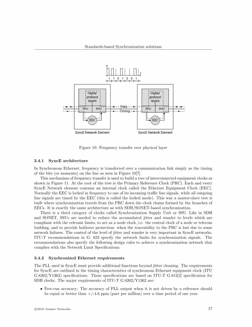
In Synchronous Ethernet, frequency is transferred over a communication link simply as the timingof the bits (or moments) on the line as seen in Figure 10[7].
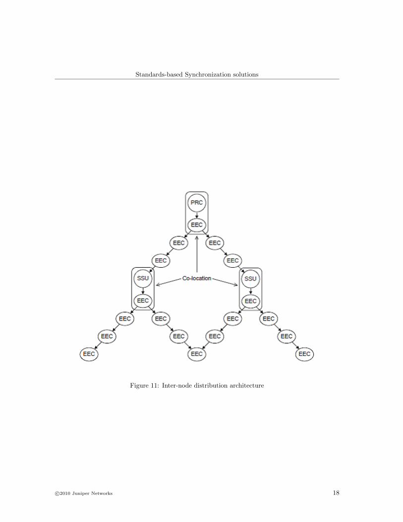
This mechanism of frequency transfer is used to build a tree of interconnected equipment clocks asshown in Figure 11. At the root of the tree is the Primary Reference Clock (PRC). Each and everySyncE Network element contains an internal clock called the Ethernet Equipment Clock (EEC).Normally the EEC is locked in frequency to one of its incoming traffic line signals, while all outgoingline signals are timed by the EEC (this is called the locked mode). This way a master-slave tree isbuilt where synchronization travels from the PRC down the clock chains formed by the branches ofEECs. It is exactly the same architecture as with SDH/SONET-based synchronization.
There is a third category of clocks called Synchronization Supply Unit or SSU. Like in SDHand SONET, SSUs are needed to reduce the accumulated jitter and wander to levels which arecompliant with the relevant limits, to act as a node clock, i.e. the central clock of a node or telecombuilding, and to provide holdover protection: when the traceability to the PRC is lost due to somenetwork failures. The control of the level of jitter and wander is very important in SyncE networks.ITU-T recommendations in G. 823 specify the network limits for synchronization signals. Therecommendations also specify the following design rules to achieve a synchronization network thatcomplies with the Network Limit Specifications.
3.4.2 Synchronized Ethernet requirements
The PLL used in SyncE must provide additional functions beyond jitter cleaning. The requirementsfor SyncE are outlined in the timing characteristics of synchronous Ethernet equipment clock (ITUG.8262/Y1362) specifications. These specifications are based on ITU-T G.813[2] specification forSDH clocks. The major requirements of ITU-T G.8262/Y1362 are:
• Free-run accuracy: The accuracy of PLL output when it is not driven by a reference shouldbe equal or better than +/-4.6 ppm (part per million) over a time period of one year.
• Holdover: The PLL constantly calculates the average frequency of the locked reference. If thereference fails and no other references are available, the PLL goes into holdover mode andgenerates an output clock based on a calculated average value.
• Reference monitoring: The PLL needs to constantly monitor the quality of its input references.If the reference deteriorates (disappears or drifts in frequency), then the PLL raises an alarm(interrupt) and switches to another valid reference.
• Hitless reference switching: If the PLL’s reference fails, then it will lock to another availablereference without phase disturbances at its output.
• Jitter and wander filtering: The PLL can be viewed as a jitter and wander filter. The narrowerthe loop bandwidth, the better the jitter and wander attenuation.
• Jitter and wander tolerance: The PLL should tolerate large jitter and wander at its input andstill maintain synchronization without raising any alarms.
A Digital PLL (DPLL) similar to DPLLs used for SONET/SDH clocks can meet these re-quirements. The major difference is that a SyncE DPLL needs to be able to lock and generateclock frequencies used in Ethernet (25MHz, 125MHz and 156.25MH) as opposed to telecom clocks(19.44MHz, 155.52MHz) used in SONET/SDH.
3.4.3 Synchronization Signaling
The Synchronization Status Message (SSM) signaling system that exists on SONET/SDH[1] net-works exists in Synchronous Ethernet too. The only difference is the communication channel usedfor transferring the SSM from clock to clock. Synchronous Ethernet uses “Ethernet SynchronizationMessaging Channel” or ESMC[6]. It consists of special Ethernet frames.
3.4.4 Synchronization solutions based on SyncE
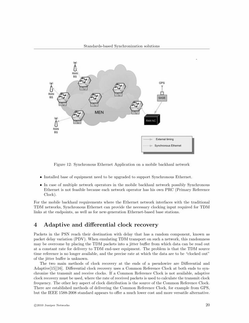
Mobile technologies like GSM, UMTS and WiMax-FDD require frequency synchronization only.For such networks Synchronous Ethernet is the ideal solution. It combines the cost-effectivenessof Ethernet with the synchronization distribution capability of SDH. The advantage, compared tostandard Ethernet, is that the base stations can now be synchronized through the network. Thefollowing figure (Figure [21]) shows a typical example of Synchronous Ethernet application in amobile backhaul network.
3.4.5 Advantages and Limitations of SyncE
Synchronous Ethernet (SyncE) is an evolution of conventional Ethernet where all Ethernet Equip-ment Clocks (EEC) are synchronized to Primary Reference Clock (PRC) which provides a fractionalfrequency accuracy of 1 part in 1011. SyncE can be used as a synchronization distribution networkfor frequency, as in the operation of base stations and NodeBs in mobile networks. The architectureof a synchronization network based on SyncE is the same as with SDH/SONET and hence it ispossible to build a mixed and compatible network. The downside is that it requires to be supportedat every hop along the chain of nodes. Also this method can only be used to distribute frequencysynchronization. Some other aspects of the Synchronous Ethernet that need to be considered are:
• The operating expenses for the management of the synchronization network based on thephysical layer are possibly higher than for packet-based solutions
Figure 12: Synchronous Ethernet Application on a mobile backhaul network
• Installed base of equipment need to be upgraded to support Synchronous Ethernet.
• In case of multiple network operators in the mobile backhaul network possibly SynchronousEthernet is not feasible because each network operator has his own PRC (Primary ReferenceClock).
For the mobile backhaul requirements where the Ethernet network interfaces with the traditionalTDM networks, Synchronous Ethernet can provide the necessary clocking input required for TDMlinks at the endpoints, as well as for new-generation Ethernet-based base stations.
4 Adaptive and differential clock recovery
Packets in the PSN reach their destination with delay that has a random component, known aspacket delay variation (PDV). When emulating TDM transport on such a network, this randomnessmay be overcome by placing the TDM packets into a jitter buffer from which data can be read outat a constant rate for delivery to TDM end-user equipment. The problem is that the TDM sourcetime reference is no longer available, and the precise rate at which the data are to be “clocked out”of the jitter buffer is unknown.
The two main methods of clock recovery at the ends of a pseudowire are Differential andAdaptive[15][16]. Differential clock recovery uses a Common Reference Clock at both ends to syn-chronize the transmit and receive clocks. If a Common Reference Clock is not available, adaptiveclock recovery must be used, where the rate of received packets is used to calculate the transmit clockfrequency. The other key aspect of clock distribution is the source of the Common Reference Clock.There are established methods of delivering the Common Reference Clock, for example from GPS,but the IEEE 1588-2008 standard appears to offer a much lower cost and more versatile alternative.
Differential clock recovery requires a Common Reference Clock in order to operate. The transmittermeasures the relationship between the local clock and the Common Reference Clock, and sends thisinformation to the receiver alongside the data traffic. The receiver uses this information to recovera clock with the same relationship to the Common Reference Clock, so good frequency matchingcan be achieved. The recovered clock is not affected much by Packet Delay Variations (PDV), sincethe recovered clock is related to the common reference. The downside is that a Common ReferenceClock is required at each end station, which can prove expensive.
4.2 Adaptive Clock Recovery
When there is no Common Reference Clock available to the receiving end of the link, adaptive clockrecovery must be used. The clock recovery mechanism monitors the packet stream received fromthe Metro Ethernet PSN, and calculates the clock frequency based on the rate of data received.
The adaptive clock recovery offers good high-frequency jitter filtering, but is prone to wanderdue to Packet Delay Variation (PDV). The CES Processor Vendors have their own adaptive clockrecovery algorithms, and performance varies depending on the Metro Ethernet PSN performance andloading. Many vendors claim to meet G.823 (E1), G.824 (T1), and G.813 (Timing characteristicsof SDH equipment slave clocks (SEC)), although the network conditions during these tests is oftenunspecified.
5 Choosing a Synchronization solution
Given the complex scenarios associated with next-generation networks, operators would have toevaluate the following factors while choosing a feasible synchronization solution:
• Synchronization requirements (support of LTE TDD, FDD, CES)
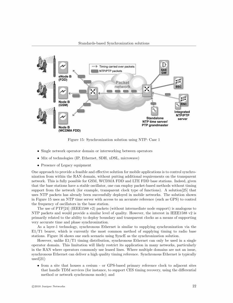
Figure 15: Synchronization solution using NTP: Case 1
• Single network operator domain or interworking between operators
• Mix of technologies (IP, Ethernet, SDH, xDSL, microwave)
• Presence of Legacy equipment
One approach to provide a feasible and effective solution for mobile applications is to control synchro-nization from within the RAN domain, without putting additional requirements on the transparentnetwork. This is fully possible for GSM, WCDMA FDD and LTE FDD base stations. Indeed, giventhat the base stations have a stable oscillator, one can employ packet-based methods without timingsupport from the network (for example, transparent clock type of functions). A solution[25] thatuses NTP packets has already been successfully deployed in mobile networks. The solution shownin Figure 15 uses an NTP time server with access to an accurate reference (such as GPS) to controlthe frequency of oscillators in the base station.
The use of PTP[24] (IEEE1588 v2) packets (without intermediate node support) is analogous toNTP packets and would provide a similar level of quality. However, the interest in IEEE1588 v2 isprimarily related to the ability to deploy boundary and transparent clocks as a means of supportingvery accurate time and phase synchronization.
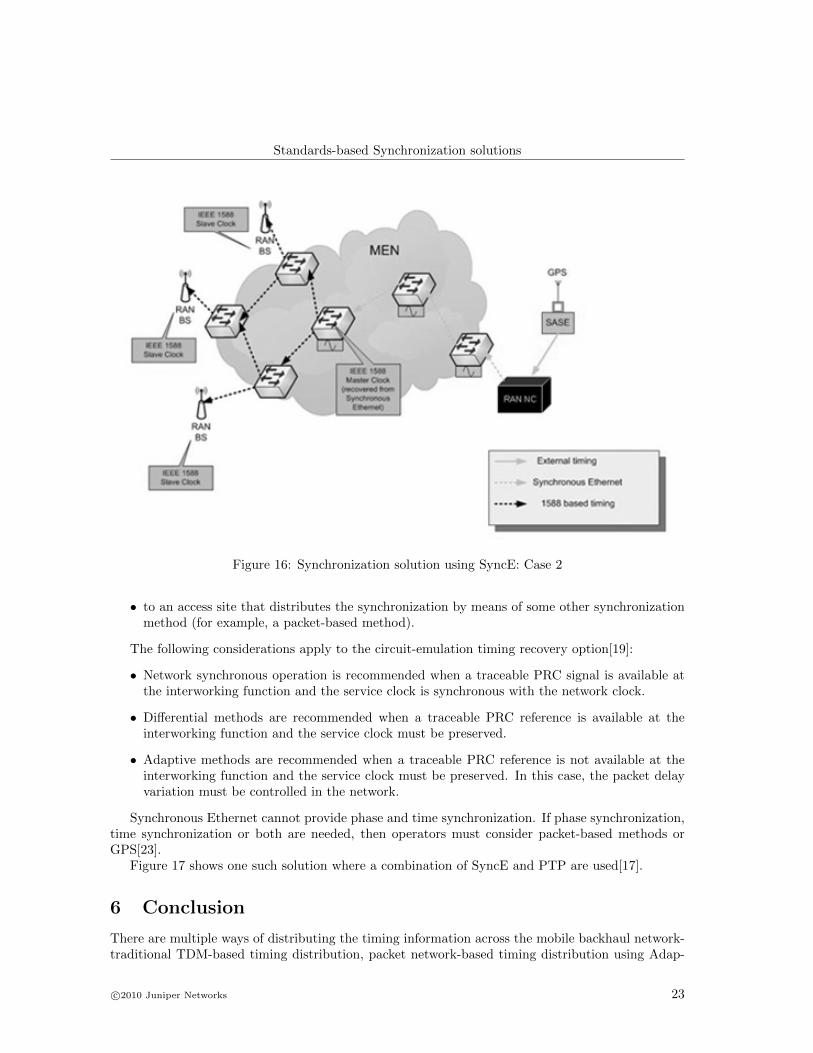
As a layer-1 technology, synchronous Ethernet is similar to supplying synchronization via theE1/T1 bearer, which is currently the most common method of supplying timing to radio basestations. Figure 16 shows one such scenario using SyncE as the synchronization solution.
However, unlike E1/T1 timing distribution, synchronous Ethernet can only be used in a singleoperator domain. This limitation will likely restrict its application in many networks, particularlyin the RAN where operators commonly use leased lines. Where multiple domains are not an issue,synchronous Ethernet can deliver a high quality timing reference. Synchronous Ethernet is typicallyused[21]:
• from a site that houses a cesium - or GPS-based primary reference clock to adjacent sitesthat handle TDM services (for instance, to support CES timing recovery, using the differentialmethod or network synchronous mode); and
Figure 16: Synchronization solution using SyncE: Case 2
• to an access site that distributes the synchronization by means of some other synchronizationmethod (for example, a packet-based method).
The following considerations apply to the circuit-emulation timing recovery option[19]:
• Network synchronous operation is recommended when a traceable PRC signal is available atthe interworking function and the service clock is synchronous with the network clock.
• Differential methods are recommended when a traceable PRC reference is available at theinterworking function and the service clock must be preserved.
• Adaptive methods are recommended when a traceable PRC reference is not available at theinterworking function and the service clock must be preserved. In this case, the packet delayvariation must be controlled in the network.
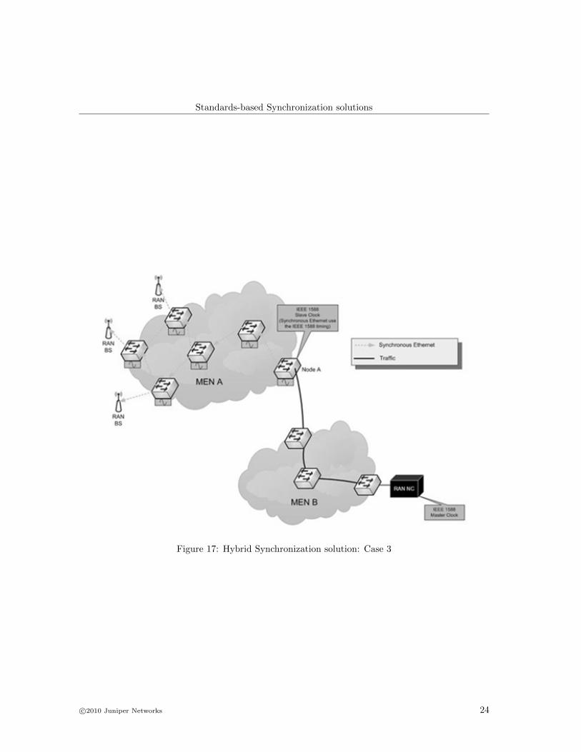
Synchronous Ethernet cannot provide phase and time synchronization. If phase synchronization,time synchronization or both are needed, then operators must consider packet-based methods orGPS[23].
Figure 17 shows one such solution where a combination of SyncE and PTP are used[17].
6 Conclusion
There are multiple ways of distributing the timing information across the mobile backhaul network-traditional TDM-based timing distribution, packet network-based timing distribution using Adap-
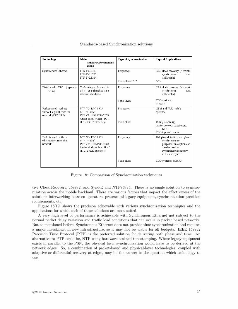
Figure 18: Comparison of Synchronization techniques
tive Clock Recovery, 1588v2, and Sync-E and NTPv3/v4. There is no single solution to synchro-nization across the mobile backhaul. There are various factors that impact the effectiveness of thesolution: interworking between operators, presence of legacy equipment, synchronization precisionrequirements, etc.
Figure 18[19] shows the precision achievable with various synchronization techniques and theapplications for which each of these solutions are most suited.
A very high level of performance is achievable with Synchronous Ethernet not subject to thenormal packet delay variation and traffic load conditions that can occur in packet based networks.But as mentioned before, Synchronous Ethernet does not provide time synchronization and requiresa major investment in new infrastructure, so it may not be viable for all budgets. IEEE 1588v2Precision Time Protocol (PTP) is the preferred solution for delivering both phase and time. Analternative to PTP could be, NTP using hardware assisted timestamping. Where legacy equipmentexists in parallel to the PSN, the physical layer synchronization would have to be derived at thenetwork edges. So, a combination of packet-based and physical-layer technologies, coupled withadaptive or differential recovery at edges, may be the answer to the question which technology touse.
[1] ITU-T. Architecture of transport networks based on the synchronous digital hierarchy(SDH). ITU-T Recommendation G.803, Geneva, Switzerland, March 2000. Available at:http://www.itu.int/rec/T-REC-G.803/en
[2] ITU-T. Timing requirements of SDH equipment slave clocks (SEC). ITU-T Recommenda-tion G.813, Geneva, Switzerland, March 2003. Available at: http://www.itu.int/rec/T-REC-G.813/en.
[3] ITU-T. Timing and synchronization aspects in packet networks. ITU-T Recommenda-tion G.8261, Geneva, Switzerland, May 2006. Available at: http://www.itu.int/rec/T-REC-G.8261/en.
[4] ITU-T. Timing characteristics of synchronous Ethernet equipment slave clocks (EEC.ITU-T Recommendation G.8262, Geneva, Switzerland, August 2007. Available at:http://www.itu.int/rec/T-REC-G.8262/en.
[5] ITU-T. Distribution of timing through packet networks. ITU-T Recommendation G.8264,Geneva, Switzerland, October 2008. Available at: http://www.itu.int/rec/T-REC-G.8264/en.
[6] John Gildred and Elias Keshishoglou. Synchronous Ethernet Specification Draft v0.39. Athttp://grouper.ieee.org/groups/1394/c/, November 2003.
[7] Oscilloquartz. Synchronization Networks based on Synchronous Ethernet.http://www.oscilloquartz.com/file/pdf/Ap20 SyncE.pdf, December 2009.
[8] John C. Eidson, Michael C. Fischer and Joe White IEEE-1588v2 IEEE Standard for a PrecisionClock Synchronization Protocol for Networked Measurement and Control Systems, version 2,2008
[9] John C. Eidson, Michael C. Fischer and Joe White IEEE-1588v1 IEEE Standard for a PrecisionClock Synchronization Protocol for Networked Measurement and Control Systems, version 1,2002
[10] EndRun Technologies. Precision Time Protocol (PTP). White Paper,http://www.endruntechnologies.com/pdf/PTP-1588.pdf, 2009
[11] David Mills. Network Time Protocol Version 4 Protocol Specification, (Internet draft).http://www.ietf.org/internet-drafts/draft-ietf-ntp-ntpv4-proto-01.txt, June 2006
[12] D. Mills, SNTP RFC 2030 Simple Network Time Protocol (SNTP) version 4 for IPv4, IPv6,and OSI. http://www.apps.ietf.org/rfc/rfc2030.html, October 1996
[13] Ya-Shian Li, Gino Crispieri and Harvey Wohlwend Using Network Time Protocol (NTP):Introduction and Recommended Practices. International SEMATECH Manufacturing Initiative,February 2006.
[14] H. Schulzrinne, S. Casner, R. Frederick and V. Jacobson RTP: A Transport Protocol for Real-Time Applications. Network Working Group, Request for Comments: 3550, July 2003
[15] Xentech. CES Clock Recovery and Distribution Techniques. White Paper,http://www.xentech.co.uk/cesclockrecovery.html, 2010
[16] Zarlink Semiconductors. Performing Clock Recovery for Circuit Emulation when using theMT9088. www.zarlink.com/zarlink/msan198-appnote.pdf, August 2002.
[17] Per Lembre. How Do Synchronous Ethernet And Precision Time Protocol Work?Part 1: Frequency Distribution and Synchronous Ethernet. http://www.en-genius.net/site/zones/networkZONE/technical notes/nett 091409, 2009.
[18] Symmetricon. The Importance of Network Time Synchronization. White Paper,http://www.symmetricom.com/resources/downloads/white-papers/, 2009.
[19] Ericsson. Synchronization in packet-based networks: challenges and solutions. White Paper,http://www.ericsson.com/news/090101 synchronization in packet based networks 20100510174712,January 2009.
[20] Juniper Networks. Mobile Backhaul Reference Architecture.http://www.juniper.net/us/en/local/pdf/reference-architectures/8030008-en.pdf, June 2009.
[21] Antonis Karvelas. Synchronization in packet-based mobile backhaul net-works. http://www.ethernetacademy.net/index.php/20090917204/Ethernet-Academy-Articles/synchronization-in-packet-networks.html,
[22] Raffaele Noro. Synchronization over packet-switching networks: Theory and Ap-plications. Phd. Thesis, Institute for computer Communications and Applications.http://icapeople.epfl.ch/noro/RNthesis.alpha.pdf, 2000.
[23] Symmetricon Synchronizing IP Mobile Networks. White Paper,http://www.symmetricom.com/resources/downloads/white-papers/, 2009.
[24] RAD communications. Synchronization and Timing in Packet-Based Mobile Backhaul. WhitePaper, http://www.rad.com/21/Synchronization Timing Packet Mobile Backhaul White Paper/11679/2009.
[25] Nortel. Mobile Backhaul Evolves with Carrier Ethernet. White Paper,http://www.nortel.com/promotions/emea/men/collateral/nn123267emea.pdf, 2008.