Synchronizing Video Cameras with Non-Overlapping Fields of View Darlan N. Brito, Fl´ avio L. C. P´ adua Mestrado em Modelagem Matem´ atica e Computacional Centro Federal de Educac ¸˜ ao Tecnol´ ogica de Minas Gerais Av. Amazonas, 7675, Belo Horizonte, MG, Brasil {darlan,cardeal}@lsi.cefetmg.br Rodrigo L. Carceroni Depart. de Ciˆ encia da Computac ¸˜ ao Universidade Federal de Minas Gerais Av. Antˆ onio Carlos, 6627, BH, MG, Brasil [email protected]Guilherme A. S. Pereira Depart. de Engenharia El´ etrica Universidade Federal de Minas Gerais Av. Antˆ onio Carlos, 6627, BH, MG, Brasil [email protected]Abstract This paper describes a method to estimate the tempo- ral alignment between N unsynchronized video sequences captured by cameras with non-overlapping fields of view. The sequences are recorded by stationary video cameras, with fixed intrinsic and extrinsic parameters. The proposed approach reduces the problem of synchronizing N non- overlapping sequences to the robust estimation of a sin- gle line in R N+1 . This line captures all temporal relations between the sequences and a moving sensor in the scene, whose locations in the world coordinate system may be es- timated at a constant sampling rate. Experimental results with real-world sequences show that our method can accu- rately align the videos. 1. Introduction In this work we consider the problem of temporal syn- chronization (temporal alignment) of multiple video se- quences, captured from distinct viewpoints by cameras with non-overlapping fields of view. Normally, the temporal mis- alignment between video sequences occurs when the in- put sequences have different frame rates, or when there is a time shift between the sequences (e.g. when the cam- eras are not activated simultaneously). Examples of appli- cations where video synchronization is essential include three-dimensional photogrammetric analysis [16], periodic motion detection and segmentation [12], multi-sensor align- ment for image fusion [4] and video metrology from televi- sion broadcasts [18]. Figure 1. A 3D scene is viewed simultane- ously by N stationary cameras located at distinct viewpoints, whose fields of view do not necessarily overlap. A moving sensor crosses the fields of view of all cameras. Unfortunately, even though synchronization can be per- formed in hardware, for example, by embedding a times- tamp in the video stream or sending a synchronization sig- nal to cameras [11], this can be costly and must be set up prior to recording. Alternatively, software algorithms can be used to recover synchronization from visual cues and this strategy is used in the present work. A reliable algorithm for the solution of the asynchronism problem between multiple video sequences should be able to handle cases like [2]: • unknown frame rates of the cameras; • arbitrary time shift between the sequences;
Transcript
Synchronizing Video Cameras with Non-Overlapping Fields of View
Darlan N. Brito, Flavio L. C. PaduaMestrado em Modelagem Matematica e Computacional
Centro Federal de Educacao Tecnologica de Minas GeraisAv. Amazonas, 7675, Belo Horizonte, MG, Brasil
{darlan,cardeal}@lsi.cefetmg.br
Rodrigo L. CarceroniDepart. de Ciencia da Computacao
Universidade Federal de Minas GeraisAv. Antonio Carlos, 6627, BH, MG, Brasil
This paper describes a method to estimate the tempo-ral alignment between N unsynchronized video sequencescaptured by cameras with non-overlapping fields of view.The sequences are recorded by stationary video cameras,with fixed intrinsic and extrinsic parameters. The proposedapproach reduces the problem of synchronizing N non-overlapping sequences to the robust estimation of a sin-gle line in RN+1. This line captures all temporal relationsbetween the sequences and a moving sensor in the scene,whose locations in the world coordinate system may be es-timated at a constant sampling rate. Experimental resultswith real-world sequences show that our method can accu-rately align the videos.
1. Introduction
In this work we consider the problem of temporal syn-chronization (temporal alignment) of multiple video se-quences, captured from distinct viewpoints by cameras withnon-overlapping fields of view. Normally, the temporal mis-alignment between video sequences occurs when the in-put sequences have different frame rates, or when there isa time shift between the sequences (e.g. when the cam-eras are not activated simultaneously). Examples of appli-cations where video synchronization is essential includethree-dimensional photogrammetric analysis [16], periodicmotion detection and segmentation [12], multi-sensor align-ment for image fusion [4] and video metrology from televi-sion broadcasts [18].
Figure 1. A 3D scene is viewed simultane-ously by N stationary cameras located atdistinct viewpoints, whose fields of view donot necessarily overlap. A moving sensorcrosses the fields of view of all cameras.
Unfortunately, even though synchronization can be per-formed in hardware, for example, by embedding a times-tamp in the video stream or sending a synchronization sig-nal to cameras [11], this can be costly and must be set upprior to recording. Alternatively, software algorithms canbe used to recover synchronization from visual cues and thisstrategy is used in the present work. A reliable algorithm forthe solution of the asynchronism problem between multiplevideo sequences should be able to handle cases like [2]:
• unknown frame rates of the cameras;
• arbitrary time shift between the sequences;
• arbitrary object motion and speed;
• presence of tracking failures, that is, individual scenepoints cannot be tracked reliably over many frames;
• computational efficiency should degrade grace-fully with increasing number of video sequences;
• unknown user-defined camera set-up;
These requirements have directed us during the develop-ment of our approach, which operates under all of theabove conditions except the last one. In particular, we as-sume that the camera set-up is composed by stationary cam-eras, whose intrinsic and extrinsic parameters are known a-priori.
Our method is derived from the method presented in [2]and is based on the concept of a timeline. Consider the sce-nario illustrated in Figure 1. Given N non-overlapping se-quences, the timeline is a line in <N+1 that completely de-scribes all temporal relations between the sequences and amoving sensor in the viewed scene. A key property of thetimeline is that even though knowledge of the timeline im-plies knowledge of the sequences’ temporal alignment, wecan compute points on the timeline without knowing thisalignment [2].
Using this property as a starting point, the temporalalignment problem for N sequences is reduced to the prob-lem of estimating a single line of N + 1 dimensions from aset of appropriately-generated points in <N+1.
Video alignment algorithms can be divided in two maingroups: the feature–based methods and the direct methods.Feature–based methods [1, 5, 12–17, 23–27] extract all in-formation needed to perform temporal alignment from de-tected features, for example, frame–to–frame object motion,or object trajectories throughout an entire sequence. On theother hand, direct methods [3, 4, 6, 7, 19, 21, 22] extract thatinformation from the intensities and intensity gradients ofall pixels that belong to overlapping regions.
Therefore, direct methods tend to align sequences moreaccurately if their appearances are similar, while feature–based methods are widely prescribed for sequences withdissimilar appearance such as those acquired with widebaselines, different magnifications, or by cameras with dis-tinct spectral sensitivities. Our approach belongs to groupof feature–based methods.
Most existing feature-based techniques [5,12,14,17,23–28] were developed for overlapping video sequences. More-over, most of these works conduct an explicit search in thespace of all possible alignments and are aware of use con-straints based on correspondences between points of ob-ject trajectories. The combinatorial nature on that search re-quires several additional assumptions to make it manage-able [2]. These include assuming known frame rates; re-stricting N to be two; assuming that the temporal misalign-ment is an integer; and assuming that this misalignment falls
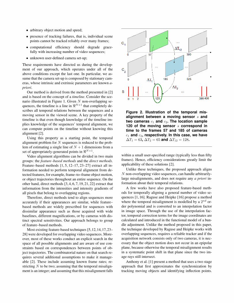
Figure 2. Illustration of the temporal mis-alignment between a moving sensor s andtwo cameras c1 and c2. The location sample120 of the moving sensor s correspond intime to the frames 57 and 185 of camerasc1 and c2, respectively. In this case, we have∆T1 = 63, ∆T2 = 65 and ∆T12 = 128.
within a small user-specified range (typically less than fiftyframes). Hence, efficiency considerations greatly limit theapplicability of these solutions [2].
Unlike these techniques, the proposed approach alignsN non-overlapping video sequences, can handle arbitrarily-large misalignments, and does not require any a priori in-formation about their temporal relations.
A few works have also proposed feature-based meth-ods for temporally aligning a general number of video se-quences [1, 16]. Raguse and Heipke [16] propose a methodwhere the temporal misalignment is modelled by a 2nd or-der polynomial and is converted to an interpolation factorin image space. Through the use of the interpolation fac-tor, temporal correction terms for the image coordinates arecalculated and introduced in the functional model of a bun-dle adjustment. Unlike the method proposed in this paper,the technique developed by Raguse and Heipke works withoverlapping sequences, requires a reliable tracker and if theacquisition network consists only of two cameras, it is nec-essary that the object motion does not occur in an epipolarplane, because otherwise the temporal misalignment resultsin a systematic point shift in that plane since the two im-age rays still intersect.
Anthony et al. [1] present a method that uses a two stageapproach that first approximates the synchronization bytracking moving objects and identifying inflection points.
Their method is closely related to the technique proposedby Carceroni et al. [2] and proceeds to refine the estimateusing a consensus based matching heuristic to find movingfeatures that best agree with the pre-computed camera ge-ometries from stationary image features. However, unlikeour approach, it was developed to work with overlappingsequences, requires the presence of at least three camerasmonitoring the scene and the use of a reliable tracker.
Finally, there are only a few works based on direct meth-ods to align sequences without any overlap [4,19]. The mostrelevant work was developed by Caspi and Irani [4], and,unlike our approach, it does not work with stationary cam-eras. Specifically, it only works with sequences acquired bypairs of cameras that remain rigidly attached to each otherwhile moving relative to a mostly rigid scene.
2. Problem Formulation
Suppose that a dynamic scene is viewed simultaneouslyby N stationary cameras located at distinct viewpoints,whose fields of view do not necessarily overlap. Moreover,consider the presence of a moving sensor in the 3D scene,whose locations in the world coordinate system may be esti-mated with a constant sampling rate. Suppose also that thissensor crosses the fields of view of all cameras, as illus-trated in Figure 1.
We assume that each camera captures frames with a con-stant, unknown frame rate and that the cameras as well asthe moving sensor are unsynchronized, i.e., they began cap-turing frames and location samples at a different time withpossibly-distinct sampling rates. In Figure 2, for example,we illustrate the temporal misalignment between a mov-ing sensor and two cameras. In that example, the locationsample 120 of the moving sensor s correspond in time tothe frames 57 and 185 of cameras c1 and c2, respectively.Therefore, the temporal misalignment between camera c1and sensor s is ∆T1 = 63, while the temporal misalign-ment between camera c2 and sensor s is ∆T2 = 65. Anal-ogously, the temporal misalignment between the cameras is∆T12 = 128.
The constant sampling rate assumption for the videocameras and the moving sensor implies that the tempo-ral coordinates (time stamps) of the sensor samples andthe temporal coordinates (frame numbers) of all video se-quences are related by a onedimensional affine transforma-tion [2]:
ti = αi ts + βi, (1)
where ti and ts denote the temporal coordinates of the i-thvideo sequence and the temporal coordinates of the movingsensor, respectively. The parameters αi, βi are unkown con-stants describing the temporal dilation and temporal shift,respectively, between the sensor and the i-th sequence. Ingeneral, these constants will not be integers [2].
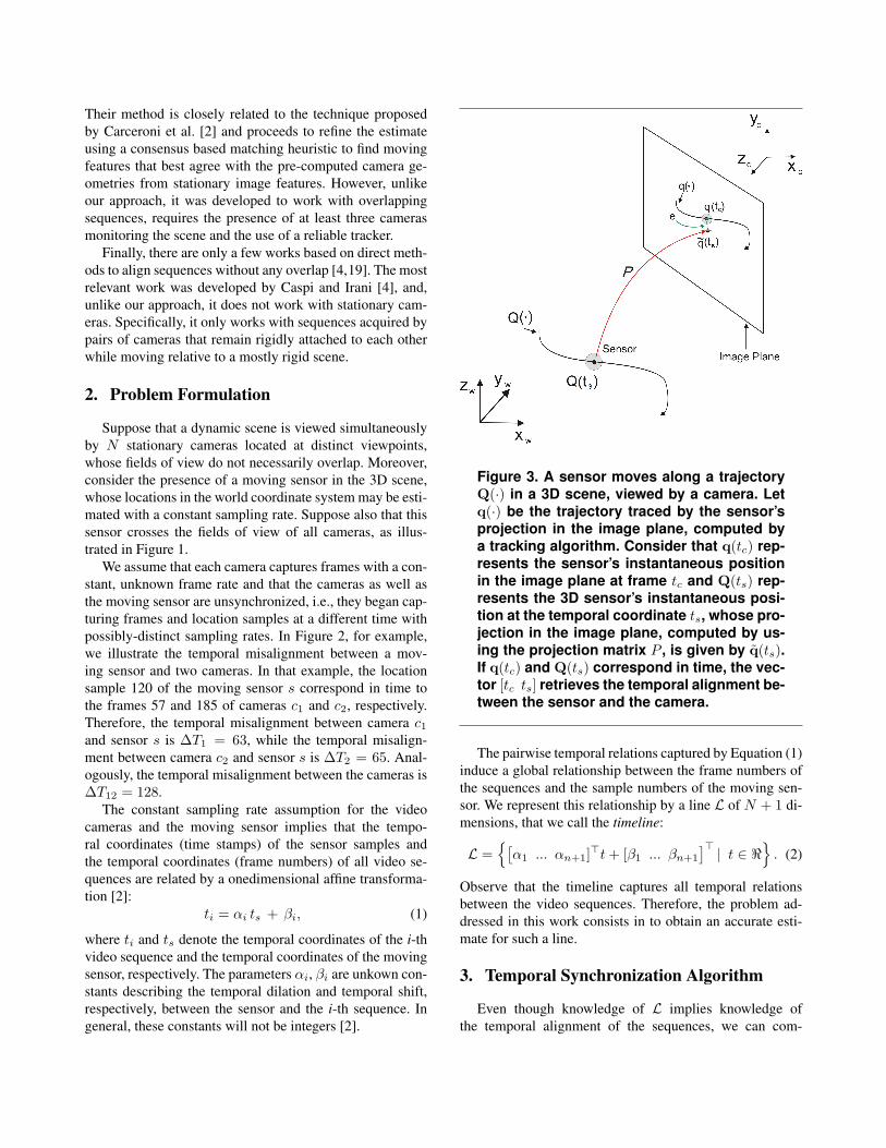
Figure 3. A sensor moves along a trajectoryQ(·) in a 3D scene, viewed by a camera. Letq(·) be the trajectory traced by the sensor’sprojection in the image plane, computed bya tracking algorithm. Consider that q(tc) rep-resents the sensor’s instantaneous positionin the image plane at frame tc and Q(ts) rep-resents the 3D sensor’s instantaneous posi-tion at the temporal coordinate ts, whose pro-jection in the image plane, computed by us-ing the projection matrix P , is given by q(ts).If q(tc) and Q(ts) correspond in time, the vec-tor [tc ts] retrieves the temporal alignment be-tween the sensor and the camera.
The pairwise temporal relations captured by Equation (1)induce a global relationship between the frame numbers ofthe sequences and the sample numbers of the moving sen-sor. We represent this relationship by a line L of N + 1 di-mensions, that we call the timeline:
L ={[α1 ... αn+1]>t+ [β1 ... βn+1
]> | t ∈ <} . (2)
Observe that the timeline captures all temporal relationsbetween the video sequences. Therefore, the problem ad-dressed in this work consists in to obtain an accurate esti-mate for such a line.
3. Temporal Synchronization Algorithm
Even though knowledge of L implies knowledge ofthe temporal alignment of the sequences, we can com-
(a) (b)
Figure 4. (a) Voting Space for the camera c1 and the moving sensor s. (b) Voting Space for the cam-era c2 and the moving sensor s. Each point in (a) and (b) represents candidate temporal alignments.The reconstructed lines tc1 = 3.9979ts − 269.8932 and tc2 = 4.0028ts + 21.6761 describe the temporalalignments between the sensor and cameras c1 and c2, respectively. From those equations we ob-tain the new equation tc2 = 1.0011tc1 +291.8797 that retrieves the temporal alignment between the twovideo sequences.
pute points on the timeline without knowing the sequences’alignment [2]. This observation leads to a simple algorithmfor reconstructing the timeline by using a moving sensor inthe scene that crosses the fields of view of all cameras.
Specifically, consider Figure 3 where a sensor movesalong a trajectory Q(·) in a 3D scene, viewed by a cam-era. Suppose that the 3D sensor’s trajectory in the world co-ordinate system may be estimated by using a localizationsystem as the one proposed by Garcia et al. [9]. Let q(·)be the trajectory traced by the sensor’s projection in the im-age plane, computed by an object tracking algorithm [10].
Assuming that the camera is calibrated, we may estimatefor each 3D sensor’s position its corresponding projectionin the image plane. In Figure 3, for example, Q(ts) repre-sents the 3D sensor’s instantaneous position at the tempo-ral coordinate ts and its projection q(ts) in the image planewas computed by using the projection matrix P , obtainedduring the calibration of the camera.
Our key observation is that, by determining correspon-dences between 2D sensor positions in the image plane,computed by the tracking algorithm and by the projectionmatrix P, we may also determine correspondences betweenthe temporal coordinates of the frame numbers of the videosequence and the sample numbers of the moving sensor.
Consider, for example, that q(tc) in Figure 3 representsthe sensor’s instantaneous position in the image plane atframe tc, computed by the tracker. Assuming that q(tc) and
Q(ts) correspond in time, the projection q(ts) of Q(ts)should coincide with q(tc) or stay at a distance of e pix-els, due to errors in the camera calibration and tracking al-gorithms. From this observation, we may also establish cor-respondence between the temporal coordinates tc and ts ofq(tc) and q(ts), respectively, since they represent the same3D instantaneous position Q(ts) of the sensor. In fact, wemay estimate for each camera c and the moving sensor sa set V of 2D points with coordinates [tc ts] that repre-sent “candidate” temporal alignments for the camera andthe sensor. Specifically, the set V defines a voting space thatis built as follows:
V ={
[tc ts]> | D (q(tc), q(ts)) ≤ ε,}, (3)
where D(·) denotes the euclidean distance between thepoints q(tc) and q(ts), and ε denotes a tolerance in pix-els, whose value is given by the average of the errors in thecamera calibration and tracking algorithms.
In Figures 4(a)-(b), we illustrate two examples of votingspaces obtained in the real experiment described in the nextsection. In general, the set V described in Equation (3) willcontain outliers. To reconstruct the timeline in the presenceof outliers, we use the RANSAC algorithm [8]. RANSACcan be regarded as an algorithm for robust fitting of mod-els in the presence of many data outliers. Since it gives usthe opportunity to evaluate any estimate of a set of parame-ters no matter how accurate the method that generated this
solution might be, the RANSAC method represents an in-teresting approach to the solution of many computer visionproblems [2].
The algorithm randomly chooses a pair of candidate tem-poral alignments to define the timeline, and then computesthe total number of candidates that fall within an δ-distanceof this line. These two steps are repeated for a numberof iterations. Provided sufficient repetitions are performed,RANSAC is expected to identify solutions computed fromoutlier-free data. Therefore, the two critical parameters ofthe algorithm are the number k of RANSAC iterations andthe distance δ. To determine k, we use the formula
k =⌈
log(1− p)log(1− r2)
⌉, (4)
where p is the probability that at least one of our random se-lections is an error-free set of candidates and r is the proba-bility that a randomly-selected candidate is an inlier.
Equation (4) expresses the fact that k should be largeenough to ensure that, with probability p, at least onerandomly-selected pair of candidates is an inlier. We usedp = 0.99 and r = 0.05 (k = 1840 iterations) for our ex-periments, which are conservative values that lead to accu-rate results in our experiments. To compute the distance δ,we observe that δ can be thought of as a bound on the dis-tance between tracked sensor locations in the input camerasand their associated projections.
After the use of RANSAC, the last step consists in to ap-ply the least-squares method over the data set estimated tocompute the timeline parameters. By combining the com-puted equations ti = αits + βi with parameters αi andβi, i = 1, ..., N , we may obtain new equations that capturethe temporal relation between any two arbitrary sequences iand j, as well as the line L that captures the global relation-ship between the sequences.
4. Experimental Results
To demonstrate the applicability of our algorithm,we present experimental results with real-world se-quences. Specifically, we tested our approach on atwo-view dataset of an indoor scene. Image dimen-sions in both datasets were about 720 × 480 pixels. Thedata were acquired by two cameras Sony DCR-SR62 with-out significant overlap between their fields of view andthat worked with identical frame rate of 30fps, im-plying a unit ground-truth temporal dilation (α = 1).The ground-truth temporal shift between the video se-quences was β = 292 ± 0.5 frames. The values of themain parameters used in our temporal alignment algo-rithm are listed in Table 4.
The moving sensor that crossed the fields of view of bothcameras was a robot Pioneer 2 AT, produced by Active Me-
Parameters Meaning Values
εTolerance used duringthe construction of thevoting space
10
p
RANSAC parameter:probability that at least
one of our randomselections is an error-free
set of candidates0, 99
r
RANSAC parameter:probability that a
randomly-selectedcandidate is an inlier
0, 05
δ
RANSAC parameter:tolerance for the distance
between a candidatetemporal alignment and
the timeline0, 5
Table 1. Values of the main parameters of ourtemporal alignment algorithm.
dia. The 3D localization data of the sensor were estimatedat a rate of 7.5 samples per second by using the visual lo-calization system proposed by Garcia et al. [9]. The framesin the resulting video sequences contain a single rigid ob-ject (sensor) moving over a static background, along a fairlysmooth trajectory, as illustrated in Figures 5(a)-(b). We usedthe WSL tracker [10] to track the sensor (blue trajectories inFigures 5(a)-(b)). WSL was initialized manually in the firstframe of each sequence.
The cameras were calibrated according to the algorithmimplemented by Strobl et al. [20]. In Figures 5(a)-(b) weshow the projections of the 3D sensor locations in the im-age planes of both cameras (red trajectories). Observe thatthose projections defined very noisy trajectories in the im-age planes.
We use the average temporal alignment error as our basicmeasurement for evaluating the accuracy of our approach.Specifically, its value is given by the average of the abso-lute values of the differences between the temporal coordi-nates computed by the estimated line and the temporal coor-dinates computed by the “ground-truth” affine transforma-tion in Equation (5):
tgc2= tc1 + 292, (5)
where tc1 represents the temporal coordinate of the se-quence acquired by camera c1 and tgc2
represents its corre-sponding temporal coordinate in the sequence acquired by
camera c2, computed by the “ground-truth” affine transfor-mation.
Therefore, if tec2represents the corresponding temporal
coordinate of tc1 , computed by using the line estimatedby our method, the average temporal alignment error εt isgiven by:
εt =1M
M−1∑tc1=0
∣∣tec2(tc1)− tgc2
(tc1)∣∣ . (6)
where M is the number of frames in the video sequence ac-quired by camera c1 (in this case, M = 756).
In Figures 4(a)-(b), we show the estimated voting spacesfor the moving sensor s and the two cameras c1 and c2 usedin our experiment. The reconstructed lines tc1 = 3.9979ts−269.8932 and tc2 = 4.0028ts + 21.6761 describe the tem-poral alignments between the sensor and cameras c1 and c2,respectively. From those equations we obtain the new equa-tion tec2
= 1.0011tc1 + 291.8797 that retrieves the tempo-ral alignment between the two video sequences. Accordingto Equation (6), the reconstructed line gives an average tem-poral alignment error of 0.9764 frames or 32.5 miliseconds.
Therefore, our results show that our method may worksuccessfully even when the video sequences have large tem-poral misalignments (in this example, 292 frames). Thisscenario may be critical for most of the current tempo-ral alignment methodologies. Figures 5(c)-(d) confirm thatthe computed temporal alignment between the video se-quences was effectively retrieved. In Figure 5(c), the be-fore alignment image was created by superimposing thegreen band of a frame tc2 with the red and blue bandsof frame tc1 = (tc2 − βg)/αg , using ground truth timelinecoefficients αg and βg . Observe the temporal misalign-ment between the video sequences. In Figure 5(d), the afteralignment image was created by replacing the green bandof frame tc2 with that of frame tc1 = (tc2 − βe)/αe, withαe, βe computed by our algorithm. Note that the sequenceswere aligned quite well and the “double exposure” artifactsdisappeared.
5. Conclusions
This paper presents an approach to estimate the tempo-ral alignment between N unsynchronized video sequencescaptured by cameras with non-overlapping fields of view.The results suggest that timeline reconstruction provides asimple and effective method for temporally aligning multi-ple video sequences that do not have spatial overlap.
Additional theoretical investigations need to be consid-ered for future work. Firstly, the methodology proposed as-sumes that all cameras acquire frames at constant (albeitnot necessarily identical) temporal sampling rates. Basedon that assumption, the approach model the temporal mis-
alignment between a pair of video sequences as an one-dimensional affine transformation. The pairwise temporalrelations modelled by that transformation induce a globalrelationship between the frame numbers of the input se-quences and the sample numbers of the moving sensor.However, such a kind of mathematical modelling is not ap-propriate when some sequences work with variable framerates. Therefore, the development of an alternative mathe-matical model, which can couple with this problem repre-sents an important topic for future research.
Another important direction for future work is 3D scenereconstruction. By combining the temporal alignment ap-proach with multi-view stereo techniques, important ad-vances could be achieved in the development of robust sys-tems for reconstructing 3D dynamic scenes.
We are currently investigating the problem of esti-mating the temporal synchronization in wireless sen-sor networks, by adapting the methodology proposed byCarceroni et al [2]. Unlike existing methods, which are fre-quently based on adaptations of techniques originally de-signed for wired networks with static topologies, or evenbased on solutions specially designed for ad hoc wire-less sensor networks, but that have a high energy consump-tion and a low scalability regarding the number of sensors,we are developing an approach that reduces the prob-lem of synchronizing a general number N of sensors to therobust estimation of a single line in RN+1. In this new sce-nario, we consider that the moving sensors are distributedin an environment that is viewed by one or more cam-eras.
Acknowledgments We would like to thank Pedro Shi-roma and Vilar da Camara Neto for their support with theexperiments. Flavio Padua and Darlan Brito thank the sup-port of FAPEMIG-Brazil under Proc. EDT- 162/07.
References
[1] W. Anthony, L. Robert, and B. Prosenjit. Temporal synchro-nization of video sequences in theory and in practice. InWorkshop on Motion and Video Computing, volume 2, 2005.
[2] R. Carceroni, F. Padua, G. Santos, and K. Kutulakos. LinearSequence-to-Sequence Alignment. In Proc. of IEEE Com-puter Vision and Pattern Recognition Conference, volume 1,pages 746–753, June 2004.
[3] Y. Caspi and M. Irani. A step towards sequence-to-sequencealignment. In Proc. IEEE Conference on Computer Visionand Pattern Recognition, volume 2, pages 682–689, HiltonHead Island, South Carolina, June, 13-15 2000.
[4] Y. Caspi and M. Irani. Alignment of non-overlapping se-quences. In Proc. of International Conference on ComputerVision, volume 2, pages 76–83, Vancouver, Canada, July, 9-12 2001.
[5] Y. Caspi, D. Simakov, and M. Irani. Feature-based sequence-to-sequence matching. In VAMODS (Vision and Modelling of
(a) Sensor’s trajectories in camera 1. (b) Sensor’s trajectories in camera 2.
(c) Before temporal alignment. (d) After temporal alignment.
Figure 5. (a) and (b) Trajectories of the sensor’s centroid in cameras 1 and 2, respectively. The bluetrajectories were estimated by the WSL tracker [10], while the red ones were obtained by the projec-tion of the 3D sensor’s trajectory in the image planes, using the projection matrices computed duringthe calibration of the cameras. (c) Before alignment image was created by superimposing the greenband of a frame t2 with the red and blue bands of frame t1 = (t2 − βg)/αg using ground truth timelinecoefficients αg and βg. (d) After alignment image was created by replacing the green band of the im-age with that of frame t1 = (t2 − βe)/αe, with αe, βe computed by our algorithm. Deviations from theground-truth alignment cause “double exposure” artifacts.
Dynamic Scenes) workshop with ECCV, Copenhagen, Den-mark, May, 28-31 2002.
[6] C. Dai, Y. Zheng, and X. Li. Accurate video alignmentusing phase correlation. IEEE Signal Processing Letters,13(12):737–740, 2006.
[7] C. Dai, Y. Zheng, and X. Li. Subframe video synchroniza-tion via 3d phase correlation. In Proc. IEEE InternationalConference on Image Processing, pages 501–504, 2006.
[8] M. Fischler and R. Bolles. Random sample consensus: Aparadigm for model fitting with applications to image analy-sis and automated cartography. Communications of the ACM,24(6):381–395, June 1981.
[9] R. F. Garcia, P. Shiroma, L. Chaimowicz, and M. F. M. Cam-pos. Um Arcabouco para a Localizacao de Enxames deRobos. In Proc. of VIII SBAI, 2007.
[10] A. Jepson, D. Fleet, and T. El-Maraghi. Robust on-line ap-pearance models for visual tracking. IEEE Transactionson Pattern Analysis and Machine Intelligence, 25(10):1296–1311, 2003.
[11] I. Kitahara, H. Saito, S. Akimichi, T. Onno, Y. Ohta, andT. Kanade. Large-scale virtualized reality. In Conferenceon Computer Vision and Pattern Recognition - TechnicalSketches, 2001.
[12] I. Laptev, S. J. Belongie, P. Perez, and J. Wills. Periodic mo-tion detection and segmentation via approximate sequencealignment. In Proc. of International Conference on Com-puter Vision, volume 1, pages 816–823, 2005.
[13] K. Lee and R. D. Green. Temporally synchronising imagesequences using motion kinematics. In Proc. of Image andVision Computing New Zeland, 2005.
[14] L. Lee, R. Romano, and G. Stein. Monitoring activities frommultiple video streams: Establishing a common coordinateframe. IEEE Transactions on Pattern Analysis and MachineIntelligence (PAMI), 22:758–767, August 2000.
[15] D. W. Pooley, M. J. Brooks, A. J. van den Hengel, andW. Chojnacki. A voting scheme for estimating the syn-chrony of moving-camera videos. In Proc. IEEE Interna-tional Conference on Image Processing, volume 1, pages413–416, 2003.
[16] K. Raguse and C. Heipke. Photogrammetric synchroniza-tion of image sequences. In Proc. ISPRS Commission V Sym-posium on Image Engineering and Vision Metrology, pages254–259, 2006.
[17] C. Rao, A. Gritai, M. Shah, and T. Syeda-Mahmood. View-invariant alignment and matching of video sequences. InProc. of International Conference on Computer Vision, vol-ume 2, pages 939–945, Nice,France, October, 13-16 2003.
[18] I. Reid and A. Zisserman. Goal directed video metrology.In Proc. of the European Conference on Computer Vision,pages 647–658, 1996.
[19] O. Shakil. An efficient video alignment approach for non-overlapping sequences with free camera movement. In Proc.IEEE International Conference on Acoustics, Speech andSignal Processing, volume 2, pages 257–260, 2006.
[20] K. Strobl, W. Sepp, S. Fuchs, C. Paredes, and K. Arbter.Camera Calibration Toolbox for Matlab. http://www.vision.caltech.edu/bouguetj, 2008.
[21] Y. Ukrainitz and M. Irani. Aligning sequences and actionsby maximizing space-time correlations. In Proc. EuropeanConference on Computer Vision, pages 538–550, 2006.
[22] M. Ushizaki, T. Okatani, and K. Deguchi. Video synchro-nization based on co-occurrence of appearance changes invideo sequences. In Proc. IEEE International Conferenceon Pattern Recognition, pages 71–74, 2006.
[23] D. Wedge, D. Huynh, and P. Kovesi. Using space-time inter-est points for video sequence synchronization. In Proc. IAPRConference on Machine Vision Applications, 2007.
[24] D. Wedge, P. Kovesi, and D. Huynh. Trajectory based videosequence synchronization. In Proc. of Digital Image Com-puting: Techniques and Applications, pages 79–86, 2005.
[25] L. Wolf and A. Zomet. Correspondence-free synchroniza-tion and reconstruction in a non-rigid scene. In Workshop onVision and Modelling of Dynamic Scenes, Copenhagen, Den-mark, May 2002.
[26] L. Wolf and A. Zomet. Sequence to sequence self calibra-tion. In Proc. of the European Conference on Computer Vi-sion, volume 2, pages 370–382, May 2002.
[27] L. Wolf and A. Zomet. Wide baseline matching betweenunsynchronized video sequences. International Journal ofComputer Vision, 68(1):43–52, 2006.
[28] J. Yan and M. Pollefeys. Video synchronization via space-time interest point distribution. In Proc. of Advanced Con-cepts for Intelligent Vision Systems, 2004.