Synchronous Motor Drive Synchronous Motor Drive Control System with Control System with Prescribed Closed-Loop Prescribed Closed-Loop Speed Dynamics Speed Dynamics Dodds, J., Stephen*, Vittek, Ján** Dodds, J., Stephen*, Vittek, Ján** *University of East London, School of Computing & *University of East London, School of Computing & Technology, UK Technology, UK **University of Žilina, Faculty of Electrical **University of Žilina, Faculty of Electrical Engineering, Engineering, Dept. of Power Electrical Systems, SK Dept. of Power Electrical Systems, SK
Transcript
Synchronous Motor Synchronous Motor Drive Control System Drive Control System
with Prescribed Closed-with Prescribed Closed-Loop Speed DynamicsLoop Speed Dynamics
Synchronous Motor Synchronous Motor Drive Control System Drive Control System
with Prescribed Closed-with Prescribed Closed-Loop Speed DynamicsLoop Speed Dynamics
*University of East London, School of Computing & *University of East London, School of Computing & Technology, UKTechnology, UK
**University of Žilina, Faculty of Electrical Engineering,**University of Žilina, Faculty of Electrical Engineering,
Dept. of Power Electrical Systems, SKDept. of Power Electrical Systems, SK
Model of Permanent Model of Permanent Magnet Synchronous Magnet Synchronous MotorMotor
Model of Permanent Model of Permanent Magnet Synchronous Magnet Synchronous MotorMotor
Non-linear differential equations formulated in the magnetic field-fixed d,q co-ordinate system describe the permanent magnet synchronous motor and form the basis of the control system development.
d
dt
idiq
RsLd
p r
LqLd
p rLdLq
RsLq
idiq
p rLq PM
Ld
Lq
uduq
0
10
01
d
dt Jc i L L i ir
PM q d q d q L
1
5
d
dtr
r
d
dt Jr
el L
1
outer loop sub-plant
inner loop sub-plant Master control
law
estimator and
observers
slavecontrol
law d
dt
idiq
RsLd
p r
Lq
Ld
p rLdLq
RsLq
idiq
p rLq PM
Ld
Lq
uduq
0
10
01
d
dt Jc i L L i i
Jr
PM q d q d q L el L
1 1
5
d
dtr
r
r
rL
I
U
inner loopouter loop
Idem
dem
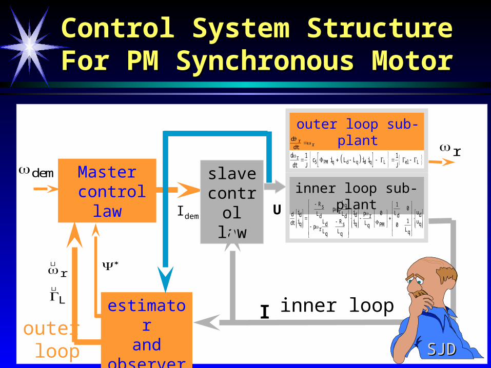
Control System Structure Control System Structure For PM Synchronous MotorFor PM Synchronous Motor
SJDSJD
Complete control structure of electric drive Complete control structure of electric drive with synchronous motorwith synchronous motor
Transf.
dq /
and
a,b,c
Master
control law SMPM
Slave control
law
Transf.
abc /
and
d,q
Angular velocity
Extractor
Discrete
two phase
oscillator
Mg. flux
calculator
Sliding mode Observer
Filtering observer
iqidud uq
iq
id
ua,b,c
d
q
vd_ekv
vq_ekv
r
L
r
id
iq
ia ib
ua
ub
uc
ib_dem
ia_dem
ic_dem
id_dem
iq_dem
r d_
ibia ic
POWER
electronics
Discrete Time Two-Phase Discrete Time Two-Phase OscillatorOscillator
The discrete time two-phase oscillator produces the transformation matrix elements, needed for the transformation
blocks.
x x p h x
x x p h x
x x p h x
k k r k
k k r k
k k r k
1 1 1 2
2 1 2 1 1
3 1 1 112 2 1
where the new transformation matrix elements
are equal to and . sin r kt X 2 1 cos
r kt X 3 1
Master Control Law Master Control Law
demanded dynamic
d
d t Tr
d r
1
1
d
d t Jc i ir
d q q d L
15
d d q qi i a
a I cos( )
linearising function
1 15
1Jc i i
Td q q d L d r
vector control terms
90o
a 0
i
i
JT
c
d dem
q dem
L d r
d q
q
d
1
52 2
d d q qi i 0
demanded values of the current components
motor equation
Acceleration Demands for Three Acceleration Demands for Three Various DynamicsVarious Dynamics
First Order DynamicFirst Order Dynamic
rd1
d T
1a dyn d r
J
T
1*
0 0.2 0.4 0.6 0.8 10
10
20
30
40
50
60
70
80
90
100
=f(t)
Second Order DynamicSecond Order Dynamic dyn dJ a *
d
dtf t
0 0.5 1 1.5-20
0
20
40
60
80
100
120
=1 =1.5 =0.5
=f(t)
Constant AccelerationConstant Acceleration
1
dd T
a
dyn d d rJ a sign * * 0 0.5 1 1.5 2
-100
-80
-60
-40
-20
0
20
40
60
80
100
d=f(t)
id=f(t)
ndd
dnrd2ndnd
aa
ha2aa
_
_ *ˆ
A High Gain Proportional Control Law with Voltage Saturation Limits was used for simulation
Bang-Bang Control Law Operating in the Sliding Mode (switching strategy for two-phase version is
satisfactory determined).
Slave Control LawSlave Control Law
U sgn I I Udmax
U sat I I U GI d
,max
Proportional High Gain Slave Control Law
Bang-Bang Slave Control Law
The Sliding Mode Observer and The Sliding Mode Observer and Angular Velocity ExtractorAngular Velocity Extractor
The basic stator current vector pseudo sliding-mode observer is given by:
d
dt
i
i
L
pL
u
uv
vd
q
d
q
d
q
eq d
eq q
*
*
10
1
The required estimates is
equivalent values
where is high a gain
v
v Ki i
i i
eq d
eq qsm
d d
q q
*
*
K sm
veq
unfiltered angular velocity estimate
can be extracted
rq eq q s q
d d PM
L v R i
p L i*
For the purpose of producing a useful formula for perfect constant parameter estimates may be assumed:
v
v
R
Lp
L
L
pL
L
R
L
i
ip
Leq d
eq q
s
dr
q
d
rd
q
s
q
d
q
r
q PM
*
*
* 0
The Filtering ObserverThe Filtering Observer
where:
needs adjustment of the one parameter only.
1
s
d
1
s
K K
r
15~ ~ ~ ~ ~
Jc i L L i iPM q d q d q
k J T 2~k J T ~
2
Filtered values of and are produced by the observer based on Kalman filter
e
Jc i L L i i k e
k e
r
r PM q d q d q L
L
~
15
rL
VJ
EXPERIMENTAL RESULTSEXPERIMENTAL RESULTS
Electric drive with synchronous motor consists of synchronous machine with nominal parameters:
,, ,, P = 4 , ,P Wn 750[ ] n rad s314 [ / ] Rs 2 2. [ ]
L mH L mHd q 6 06 5 73. [ ] , . [ ] PM Vs0119. [ ],, ,,
J kgm0 00035 2. [ ] ..
Parameters of IGBT FUJI 6MBI-060 are as follows:- nominal voltage: 600 [V] , nominal current: 6x10 [A].
Current sensors are as follows:- LEM LTA 50P/SPI.
Measured Results for Synchronous Motor with Constant Acceleration
T1 = 0.1 s , d = 60 rad/s
-0.2
-2
Complex Current Current v. t
Mg. Flux v. t
Rotor SpeedObserved Values-0.2
0.5 1 0 0.5 1
0
2
0
2
0 0.5-2
0
2
0
0.2
0
Complex Mg. Flux
0 0.5-0.2
0
0.2
0
50
-500
50
100100
-2
0.2
0 -0.5
Measured Results for Synchronous Measured Results for Synchronous Motor with Constant Acceleration - Motor with Constant Acceleration -
osciloscope screenosciloscope screen
1 - angular velocity, 2 - current in phase A1 - angular velocity, 2 - current in phase A
T1 = 0.1 s , d = 60 rad/s
Experimental results for idle running Experimental results for idle running synchronous motor and first order speed synchronous motor and first order speed
demanddemand .
-5 5-5
0
5Complex Current
0 0.4-5
0
5Current v. t
-0.2 0.2-0.2
0
0.2Complex Mg. Flux
0 0.4-0.2
0
0.2Mg. Flux v. t
0 0.5 1-50
0
50
100Observed Values
-0.5 0 0.5 1-50
0
50
100Rotor Speed
T1 = 0.05 s , d = 80 rad/s
Experimental results for idle running Experimental results for idle running synchronous motor and second order synchronous motor and second order speed demand -speed demand - osciloscope screenosciloscope screen
1 - angular velocity, 2 - current in phase A1 - angular velocity, 2 - current in phase A
Tset = 0.15 s , d = 80 rad/s
Experimental results for idle running Experimental results for idle running synchronous motor and second order synchronous motor and second order
speed demandspeed demand
-5 5-5
0
5Complex Current
0 0.4-5
0
5Current v. t
-0.2 0.2-0.2
0
0.2Complex Mg. Flux
0 0.4-0.2
0
0.2Mg. Flux v. t
0 0.5 1-50
0
50
100Observed Values
-0.5 0 0.5 1-50
0
50
100Rotor Speed
Tset = 0.15 s , d = 80 rad/s
Experimental results for idle running Experimental results for idle running synchronous motor and first order speed synchronous motor and first order speed
1 - angular velocity, 2 - current in phase A1 - angular velocity, 2 - current in phase A
T1 = 0.05 s , d = 80 rad/s
-0.2 0 0.2 0.4 0.6 0.8
60
-10
0
10
20
30
40
50
Experiments with 2Experiments with 2ndnd Order Order Dynamic for Various DampingDynamic for Various Damping
Tsettl=0.3 s , d = 40 rad/s
Experimental ResultsExperimental Results for Synchronous Motor Drive for Synchronous Motor Drive Experimental ResultsExperimental Results for Synchronous Motor Drive for Synchronous Motor Drive
Constant Acceleration
First Order Dynamic
Second Order Dynamic
d=600 rpm,Tramp=0.05 s
d=800 rpm,Tsettl=0.3 s
d=600 rpm,Tsettl=0.3 s
-2 -1.5 -1 -0.5 0 0.5 1 1.5 2-2
-1.5
-1
-0.5
0
0.5
1
1.5
2Vector Animation "Stator current & Rotor flux"
Real axis
Imaginary Axis
0.0145Time [s]
0.0086Flux Norm [Vs*Vs]
81.5866Angle [deg]
Zilina1998Control of theControl of theangle between angle between rotor flux and rotor flux and stator current stator current vectorsvectors
Conclusions and RecommendationsConclusions and Recommendations
A new approach to the control of electric drives with A new approach to the control of electric drives with permanent magnet synchronous motors, based on permanent magnet synchronous motors, based on feedback linearisation has been developed and feedback linearisation has been developed and experimentally proven.experimentally proven.
Three various prescribed dynamics to speed demands Three various prescribed dynamics to speed demands were achieved.were achieved.
Further research will focus on the application of the Further research will focus on the application of the new approach to enhancement of control system for new approach to enhancement of control system for outer loop based on MRAC or SMC to improve outer loop based on MRAC or SMC to improve precision of control.precision of control.