Page 1
Acc
epte
d A
rticl
eSynergistic effect of three dimensional multi-walled carbon
nanotube/graphene nanofiller in enhancing the mechanical and thermal
properties of high performance silicone rubber
Bratati Pradhan and Suneel Kumar Srivastava�
Inorganic Materials and Nanocomposite Laboratory Department of Chemistry Indian Institute of Technology Kharagpur-721302, India
Correspondence to: Suneel Kumar Srivastava (E-mail: [email protected] )
Tel.: (+91-03222) 283334; Fax: (+91-3222) 255303
This article has been accepted for publication and undergone full peer review but has not been through the copyediting, typesetting, pagination and proofreading process, which may lead to differences between this version and the Version of Record. Please cite this article as doi: 10.1002/pi.4627
This article is protected by copyright. All rights reserved.
Page 2
Acc
epte
d A
rticl
eAbstract:
The homogeneous dispersion of nanofillers and filler–matrix interfacial interaction are
important factors in the development of high-performance polymer materials for various
applications. In the present work, a simple solution mixing method was used to prepare multi-
walled carbon nanotube (MWCNT)-graphene (G) (3:1, 1:1, 1:3) hybrids followed by their
characterization through wide angle X-ray diffraction, transmission electron microscopy and
thermogravimetric analyses. Subsequently, MWCNT-G (1:1) hybrid was used as reinforcing
filler in the formation of silicone rubber (VMQ) nanocomposites by solution intercalation and
investigated their morphology and properties. Our findings showed that MWCNT-G (0.75 wt
%)/VMQ composite exhibited significant improvements in tensile strength (110 %) and
Young’s modulus (137 %) compared to neat VMQ. Thermal stability of MWCNT-G (1 wt
%)/VMQ was maximum improved by 154 °C compared to neat VMQ. Differential scanning
calorimetry demonstrated the maximum improvement of glass transition temperature (4 °C),
crystallization temperature (8 °C) and melting temperature (5 °C) in 1 wt % MWCNT-G
filled VMQ nanocomposites with respect to neat VMQ. Swelling measurements confirmed
that the crosslink density and solvent resistance property was found to be maximum for
hybrid nanocomposites. Such improvements in the properties of MWCNT-G/VMQ
nanocomposites could be attributed to a synergistic effect of the hybrid filler.
Keywords: silicones, MWCNT, graphene, nanocomposites, mechanical properties, thermal
properties.
INTRODUCTION
In the last few years, 1D carbon nanotube (CNT)1-4 and 2D graphene5-8 have
generated considerable amount of interest due to their excellent properties. Though, the
chemical composition of both these graphitic forms are identical, graphene has the major
advantage due to abundant availability of graphite as a naturally occurring precursor and its
production cost compared to CNT. These graphitic materials find applications in solar cells,
actuators, batteries, super capacitors, optical/electrochemical devices, sensors, catalysis,
organic light emitting diodes, and field emission transistors etc.9-13 In addition, they have also
This article is protected by copyright. All rights reserved.
Page 3
Acc
epte
d A
rticl
ebeen used as effective nanofillers in order to improve the electrical, mechanical, thermal
properties of the polymers.14,15 However, the agglomeration remains one of the most common
problems in CNT as well as graphene due to the presence of inter-tubular interaction and
restacking graphene sheets respectively.16,17 In addition, the chemical stability and lack of
available functional sites on the surface also accounts for their poor dispersion in many
common organic solvents as well as in the polymer matrix.18,19 Though, the covalent
functionalization can overcome these difficulties,20 it further introduces the serious damage
on the graphitic structure deteriorating its properties. Therefore, it remains a major challenge
in finding out the ways to enhance the dispersion of graphene and CNT in the polymer
matrix/solvent preserving their intrinsic properties
Recently, the 3D materials have been receiving the considerable amount of attention
due to their interesting properties and applications.21-34 In this regard; 3D CNT/graphene
hybrids have been obtained by the hybridization of 1D MWCNT with 2D graphene, which
can overcome the dispersion problem faced by the individual fillers. It is suggested that the
nanoscale separation of the individual CNT and graphene sheets takes place due to the π−π
interaction between the 1D CNT and 2D graphene.35,36 As a result, the long and tortuous
CNT entangles with the graphene nanosheets inhibiting their aggregation and could result in
the synergistic characteristics of the hybrid filler on morphological dispersion and its
enhanced physical properties.30-33 Accordingly, the preparation of polymer nanocomposites,
e.g. polystyrene,37 epoxy,38 poly (styrene-co-butadiene-co-styrene),39 polyvinyl alcohol,40
filled with the hybrid fillers has been receiving the momentum for their advanced
applications. Recently, the effect has been made to use 3D hybrid materials to enhance the
mechanical and electrical properties of polymer nanocomposits.23,32,33 Hu et al.34 investigated
the effect of dispersion of graphene and MWCNT in silicone rubber. They concluded that the
This article is protected by copyright. All rights reserved.
Page 4
Acc
epte
d A
rticl
estrong interaction between the silicone rubber matrix and graphene/MWCNT facilitates the
excellent dispersion of MWCNT assisted by graphene.
Silicone rubber (VMQ) is one of the unique high performance elastomer due to its
excellent physical and chemical properties. However, the poor mechanical strength restricts
its multifaceted applications in many fields.41 Therefore, VMQ has been reinforced with
clay,42 nanosilica,43 carbon nanotubes,44 graphene,44 and layered double hydroxides,45 etc.
However, the further improvement in the mechanical and thermal properties of VMQ still
remains a challenge, especially in medial and aerospace applications. Recently, the electrical
conductivity and thermal diffusivity measurements have been reported on SR/MWCNT/G
nanocomposite.34 Motivated by this, we focused our work on synthesis of 3D MWCNT-
graphene hybrid reinforced VMQ nanocomposites prepared by solution intercalation and
investigated their morphology, mechanical properties, thermal stability and swelling
behavior. It is anticipated that MWCNT-graphene hybrid, due to its homogeneous dispersion
and its strong interaction with the VMQ matrix, could impart the extraordinary mechanical
and thermal properties simultaneously compared to that attained by individually filled
MWCNT or graphene nanocomposites. It is also anticipated that composites could also be
effective for electromagnetic shielding effect due to the high conductivity of the fillers
used.46,47
EXPERIMENTAL
Materials
Surface enhanced natural graphite AKA SEFG 3777 (purity 99%, particle size 19 µm,
surface area 23 m2/g) was received as a gift from the Asbury Graphite Mills, INC, Asbury,
Warren County, NJ. Carbon nanotube, multiwalled 724769 (carbon > 95%, O.D × L 6-9 nm
× 6 μm) were purchased from Sigma-Aldrich. Sodium nitrate (NaNO3) was supplied from S.
D. Fine Chemicals, India. Potassium permanganate (KMnO4), concentrated sulphuric acid
This article is protected by copyright. All rights reserved.
Page 5
Acc
epte
d A
rticl
e(H2SO4), hydrogen peroxide (H2O2) and tetrahydrofuran (THF) were procured from Merck,
India. Hydroquinone was obtained from SRL, Mumbai, India. Commercially available vinyl
terminated, linear polydimethylsiloxane base polymer with a vinyl content 0.05 mmol/g
(Baysilone U10), Baysilone U crosslinking agent 430, and Pt catalyst complex were supplied
by G.E, Bangalore, India. Ethynyl cyclohexanol (Inhibitor) was obtained from Sigma-
Aldrich. Millipore water has been used through the course of all the experiments.
Synthesis of graphite oxide (GO) and graphene (G)
Graphite oxide (GO) was prepared from graphite by the Hummers method as reported
earlier.48 According to this, 1.0 g graphite, 500 mg NaNO3 and 40 mL H2SO4 were mixed in a
three-neck flask in an ice bath (0 °C) and 3 g KMnO4 was slowly added to prevent the
temperature of the suspension from exceeding 20 °C. Then, the suspension was transferred to
a 35 ± 3 °C water bath and stirred for 30 minutes. After that, 80 mL millipore water was
added, stirred for 15 minute at 98 °C and further diluted with warm water. Subsequently, the
minimum quantity of H2O2 was added, which turned the color of the above solution from
dark brown to yellow. The suspension was filtered, rinsed with millipore water and vacuum
dried to get brown GO powder.
GO prepared earlier was suspended in millipore water and exfoliated through
ultrasonication for 1 h. The exfoliated GO was reduced to graphene nanoplatelets by
refluxing the GO solution with hydroquinone for 36 h at 120 °C and the product was
centrifuged, washed and vacuum-dried to obtain graphene denoted as G.
Preparation of MWCNT-graphene (MWCNT-G) hybrid
The appropriate amount of MWCNT and graphene were separately dispersed in THF
for 15 min sonication. The respective suspensions were mixed together and again sonicated
for 30 min followed by vacuum drying to produce MWCNT-G (3:1, 1:1 and 1:3 weight
ratios) hybrids.
This article is protected by copyright. All rights reserved.
Page 6
Acc
epte
d A
rticl
ePreparation of MWCNT/VMQ, G/SVMQ and MWCNT-G/VMQ hybrid composite
Initially, the desired amount (0.375, 0.5, 0.75, 1 and 1.5 wt %) of MWCNT-G (1:1)
hybrid was dispersed in anhydrous THF. After that, the vinyl terminated linear
polydimethylsiloxane base polymer was added to the above suspension and subjected to
sonication for 2 h. This is followed by the addition of appropriate amounts of catalyst,
inhibitor and cross-linker (V430) in a 3:1 mole ratio of hydride (crosslinker) to the vinyl
group of base polymer under continuous stirring for 1 h. The resultant mixture was cast on a
Teflon Petri dish, degassed in vacuum for 24 h at room temperature followed by curing at
165 °C (15 min) and 200 °C (4 h) in an air oven. Similar methodology was adopted for the
preparation of neat VMQ, G/VMQ and MWCNT/VMQ nanocomposites. The preparation of
MWCNT-G hybrid and MWCNT-G/VMQ hybrid nanocomposites has also been displayed in
Scheme 1.
Characterization
Wide angle X-ray diffraction (WAXD) patterns were recorded in the range of
diffraction angle 2θ = 5-40 ° and 5-60 ° with PANalytical (PW3040/60), model ‘X’ pert pro
with Cu Kα radiation (λ=0.1542 nm) at a scanning rate of 3 °/min at room temperature.
Transmission electron microscopy (TEM) analysis was taken on JEOL 2100 TEM 80
instruments operated under an acceleration voltage of 200 keV. TEM samples of MWCNT,
G, and MWCNT-G were prepared by mounting the THF suspension on the copper grid and
drying in air. TEM samples of as prepared VMQ composite films were obtained with a
thickness of a section 100 nm by ultramicrotomy using a diamond knife under cryogenic
condition.
The mechanical properties of neat VMQ and its nanocomposites were measured using
Tinius Olsen h10KS universal testing machine at 25 °C with a crosshead speed of 300
This article is protected by copyright. All rights reserved.
Page 7
Acc
epte
d A
rticl
emm/min; dumbbell shape specimens with overall length of 100 mm and width of 3 mm. In
each system, more than three specimens were tested.
Field emission scanning electron microscopy (FESEM) images were obtained on a
Carl Zeiss Supra 40 instrument at an accelerating voltage of 20 kV.
Thermo gravimetric analysis (TGA) of the MWCNT, G, MWCNT-G, neat VMQ and
VMQ nanocomposites was performed using Redcroft 870 thermal analyser, Perkin-Elmer at a
heating rate of 10 °C/min over a temperature range of 50-800 °C under nitrogen atmosphere.
Differential scanning calorimetry (DSC) of neat VMQ and VMQ nanocomposites was
conducted using Perkin Elmer Pyris differential scanning calorimetric instrument at scan rate
of 10 °C/min under nitrogen atmosphere over a range of temperature -150 to +150 °C.
The volume fraction and crosslink density of polymer and polymer composite in the
swollen network were determined using the Flory-Rehner approach.49 Previously weighed
samples were allowed to swell in toluene for 72 h at room temperature to reach equilibrium
swelling. Sample masses in the equilibrium swollen state were measured by removing it from
toluene, blot-drying with a tissue paper, weighing it and dried to a constant weight in a
vacuum oven for minimum of 24 h. According to this, the volume fraction (Vr) of neat
polymer and polymer nanocomposites has been estimated from the relation:
11
1
−−
−
+=
ssrr
rrr WW
WV
ρρρ
,where ρr (wr) and ρs (ws) are the density (weight) of polymer/composite and solvent
respectively. The crosslink density (nc) and toluene uptake (mol %) of the polymer and
polymer composite are also calculated from the relationship:
[ ])
2(
)1ln(
31
0
2
rr
rrrc VVV
VVVn
−
++−−=
χ
This article is protected by copyright. All rights reserved.
Page 8
Acc
epte
d A
rticl
ewhere, nc, V0, χ and ρr are the crosslink density, molar volume of solvent (Toluene, V0=106.8
cm3/mol), Flory-Huggins polymer–solvent interaction parameter and density of the
polymer/polymer nanocomposites respectively.
RESULTS AND DISCUSSION
Characterization of MWCNT-G hybrid
FTIR spectra of the pristine graphite, graphite oxide and graphene are represented in
Fig. S1. It is noted that observed no significant peak appears in case of graphite, which also
agree well with the reported literature.50 However, the different oxygen functionalities are
developed in its oxidation product corresponding to O-H stretching vibrations (at 3406 cm-1),
stretching vibrations from C=O (1720 cm-1), skeletal vibrations from unoxidized graphitic
domains (1626 cm-1), C-OH stretching vibrations (1218 cm-1), and C-O stretching vibrations
(1050 cm-1).51 It is also noted that intensity of the 3434 cm-1 band corresponding O-H
stretching vibration of graphene is reduced due to de-oxygenation and removal of the other
oxygen containing functional groups.52
Wide angle X-ray diffraction (WAXD) patterns of graphite, graphite oxide, and
graphene are displayed in Fig. S2. A sharp diffraction peak appears at 2θ≈26° corresponding
to the 002 plane of graphite (d002 ≈0.34 nm).53 When it is oxidized to graphite oxide, a
diffraction peak at 2θ≈13° (d001=0.68 nm) is arised.54 The presence of a diffraction peak at
2θ≈26.09° (d002 =0.341 nm) in its reduction product confirmed the formation of graphene.54
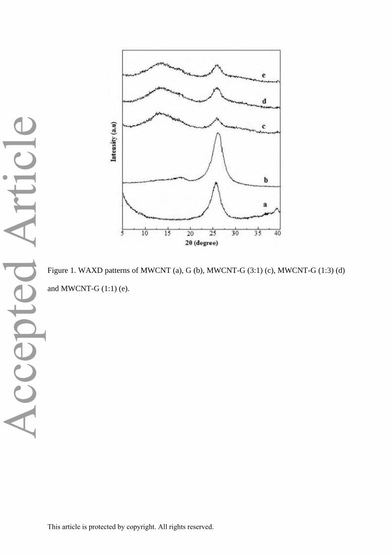
Fig. 1 shows WAXD patterns of multi walled carbon nanotube (MWCNT), graphene
(G) and MWCNT-G (3:1; 1:1; 1:3) hybrids in the range of 2θ = 5- 40 ° at the scan rates of 3
°/min. It is noted that the diffraction peak of (002) plane of graphitic carbon appear at 25.80 °
(d002 = 0.344 nm) and 26.09 ° (d002 = 0.341 nm) in MWCNT and G (JCPDS No.41-1487)
respectively. The slow scan (0.5 °/min) of the graphene and MWCNT-G hybrids in Fig. 2
clearly show that (002) peak of graphene in MWCNT-G (1:1) is maximum shifted to lower
This article is protected by copyright. All rights reserved.
Page 9
Acc
epte
d A
rticl
e2θ angle due to the π-π interaction between MWCNT and graphene. It is also noted that the
intensity of this peak is considerably reduced compared to either graphene or other MWCN-
G (3:1 and 1:3) hybrids. However, this peak is not completely disappeared suggesting that the
few graphene layers could be fused together. However, this could lead the exfoliation of
MWCNT and graphene,18 which needs further verification by TEM.
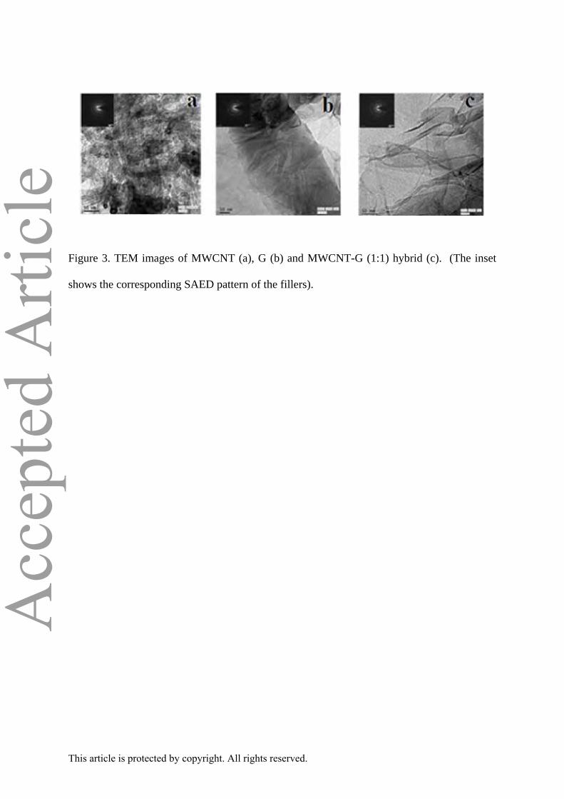
TEM image and corresponding selected area diffraction (SAED) pattern (Inset) of
respective MWCNT, G, and MWCNT-G (1:1) hybrid are displayed in Fig. 3. It clearly shows
that MWCNT are entangled into bundled and the corresponding SEAD pattern exhibits the
presence of small but strong arcs for (002), together with a ring for (100) and weak arc
corresponding to (004) diffractions.55 TEM image of graphene reveals the staking of graphene
nanosheets as expected, whereas its crystalline nature is confirmed by the presence of well-
defined diffraction spots in the SAED pattern. 54 This is also inferred from TEM images in
Fig. 3 (and Fig. S3 under supporting information) that the nanostructure of hybrids can be
tuned depending on the wt. ratios of MWCNT and graphene. The bundled MWCNT are
attached on the surface of garphene layers in MWCNT-G (3:1), whereas individual MWCNT
seems to be confined on the stacked graphene in MWCNT-G (1:3). Interestingly, TEM image
of MWCNT-G (1:1) hybrid shows that MWCNT and graphene sheets at nanoscale are
individually separated/attached on the surface of the graphene sheets. In addition, these
MWCNT are also seen to be interconnected through graphene sheets in 3D hybrid network
structure preventing the aggregation of graphene sheets in MWCNT-G.54,56 Therefore,
MWCNT-G (1:1) hybrid are likely to show an enhanced combination of thermal and
mechanical properties due to strong bonding within 1D/2D extended to extended
π−conjugated network. SAED pattern of 3D MWCNT-G (1:1) hybrid also shows the
presence of unresolved diffraction rings and spots confirming the hybridization of 1D
MWCNT and 2D graphene.
This article is protected by copyright. All rights reserved.
Page 10
Acc
epte
d A
rticl
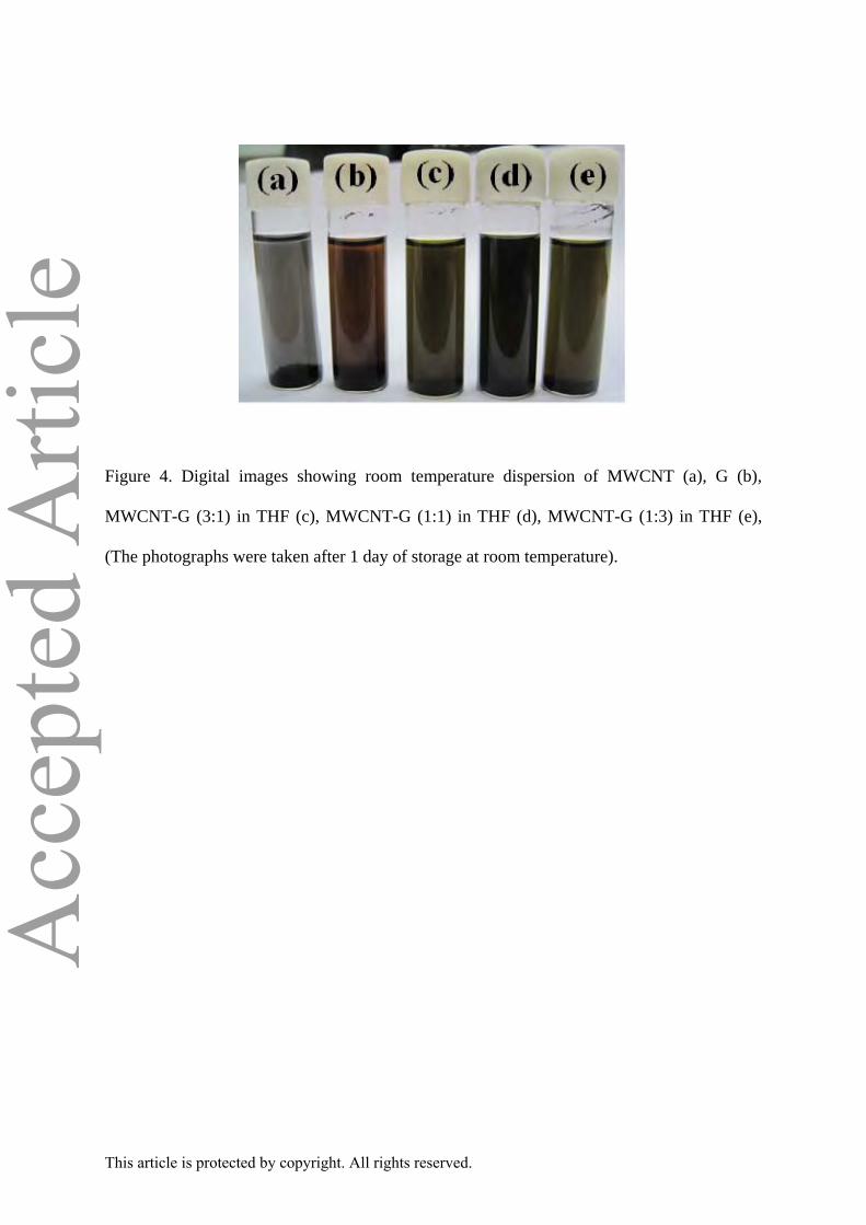
eRoom temperature stability of MWCNT, G and MWCNT-G (3:1), MWCNT-G (1:1)
and MWCNT-G (1:3) hybrid suspensions in THF has been investigated and the
corresponding findings are displayed in Fig. 4. It is anticipated that such finding could
provide a guideline in the processing of VMQ nanocomposites. It is distinctly clear that
MWCNT as well as graphene tends to sediment within 1h at the bottom of the vial. Though,
the suspension of MWCNT-G (3:1) and MWCNT-G (1:3) exhibit better colloidal stability in
THF than individual fillers, the hybrid suspensions have been precipitated within 24 h. On
the contrary, the suspension of MWCNT-G (1:1) hybrid is found to be stable even up to 7
days. This could be attributed to π-π interaction between 2D graphene and 1D MWCNT
inhibiting their aggregation and exhibiting stable colloidal suspension of 3D MWCNT-G
hybrid in THF.57 Therefore, TEM and suspension stability of MWCNT-G (1:1) hybrid further
reaffirms our inference based on XRD analysis earlier.
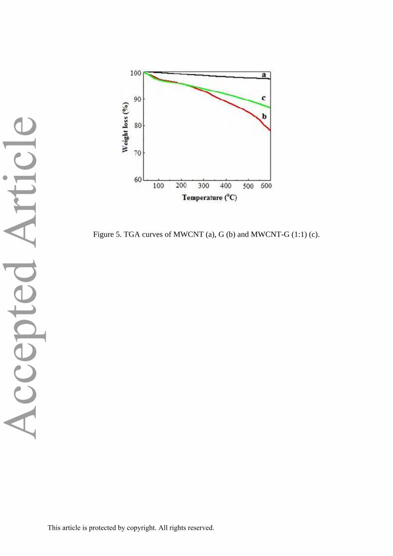
Thermal behaviour of MWCNT, G and MWCNT-G has been examined under
nitrogen atmosphere and the findings are displayed in Fig. 5. MWCNT are found to be more
or less stable in the temperature range of 30-600 °C, whereas graphene exhibits three steps
degradation under the identical condition. The first stage (30-150 °C) corresponds to 4 %
weight loss due to the presence of adsorbed water. 58 The second stage degradation (250-500
°C) is assigned to the decomposition of residual -COOH groups present on the graphene
sheets.58,59 Finally, it is followed by the another weight loss in TG in the range of 550-600 °C
due to the restoration of conjugated structures of graphene sheets at high temperature.40,60
Interestingly, MWCNT-G hybrid exhibits more or less similar thermal degradation behaviour
upto 150 °C. However, the further weight loss is significantly low above this temperature
when compared with graphene. Fig. 5 also suggests that overall residue left at 600 °C in
MWCNT-G hybrid is 86 % in contrary to either MWCNT (97 %) or graphene (78 %). This
This article is protected by copyright. All rights reserved.
Page 11
Acc
epte
d A
rticl
ecould be simply due to a balance between residual percentage of MWCNT and graphene in
the hybrid.
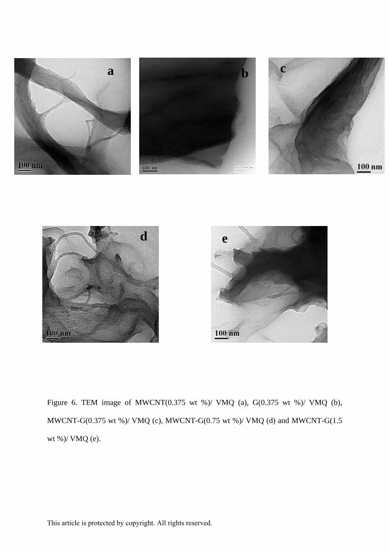
Nanostructure of VMQ nanocomposites
The choice of MWCNT-G (1:1) as reinforcing filler in the development of
VMQ nanocomposites is mainly guided by its exfoliation as evident from XRD, which has
been further established by its TEM and suspension stability in THF. TEM images of
MWCNT (0.375 wt %)/VMQ, G(0.375 wt %)/VMQ, MWCNT-G (0.375 wt %)/VMQ,
MWCNT-G(0.75 wt %)/VMQ and MWCNT-G(1.5 wt %)/VMQ nanocomposites are
displayed in Fig. 6. It clearly shows that the graphene and MWCNT filled, when
indivisuallay filled in VMQ , are agglomerated. Interestingly, TEM image of 0.375 wt % and
0.75 wt % MWCNT-G filled VMQ composite shows better dispersion and homogeneity of
MWCNT-G in VMQ matrix. Hu et al34 also recently observed that graphene is well dispersed
in the silicone rubber matrix without any aggregation of carbon nanotubes in the matrix
(silicone rubber/graphene/MWCNT=100/1/3). It is suggested that the graphene has a good
interaction with silicone rubber and carbon nanotubes facilitating the dispersion of MWCNT
in silicone rubber. When MWCNT-G loading is 1.5 wt % in VMQ, the agglomeration of the
filler is clearly evident through TEM.
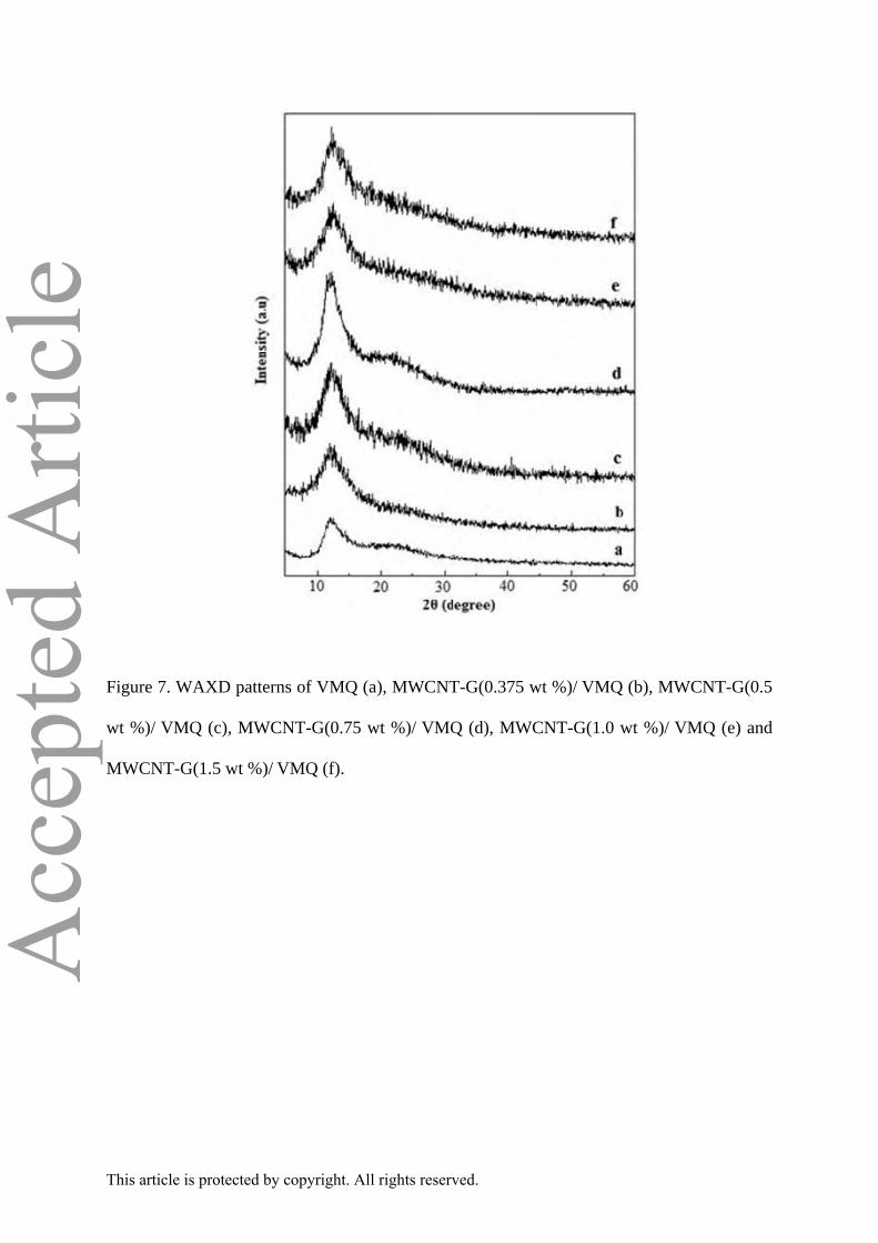
WAXD patterns of VMQ and its nanocomposites of 0.375, 0.50, 0.75, 1.0 and 1.5 wt
% filled MWCNT-G are shown in Fig. 7 and the corresponding nanocomposites of MWCNT
and graphene are presented in Fig. S4 and S5 respectively (under Supporting Information). It
is observed that neat VMQ exhibits a broad diffraction peak at 21.31° due to the amorphous
regimes of silicone rubber and a strong peak at 12.28° suggesting the inherent crystallinity of
PDMS arising from the un-stretched chain conformations.61 The crystalline packing of
MWCNT, G and MWCNT-G filled VMQ nanocomposites remain more or less unaltered. In
addition, the full width at half maximum of VMQ diffraction peak (2θ≈12.28°) in MWCNT-
This article is protected by copyright. All rights reserved.
Page 12
Acc
epte
d A
rticl
eG/VMQ nanocomposites are relatively low compared to VMQ and its individually filled
graphene and MWCNT nanocomposites prepared at the same filler loading. This is a clear
indication that the ordered-ness of VMQ segment increases in presence of MWCNT-G
hybrids due to the interfacial interaction between the hybrid filler and VMQ matrix.62
Mechanical properties of VMQ nanocomposites
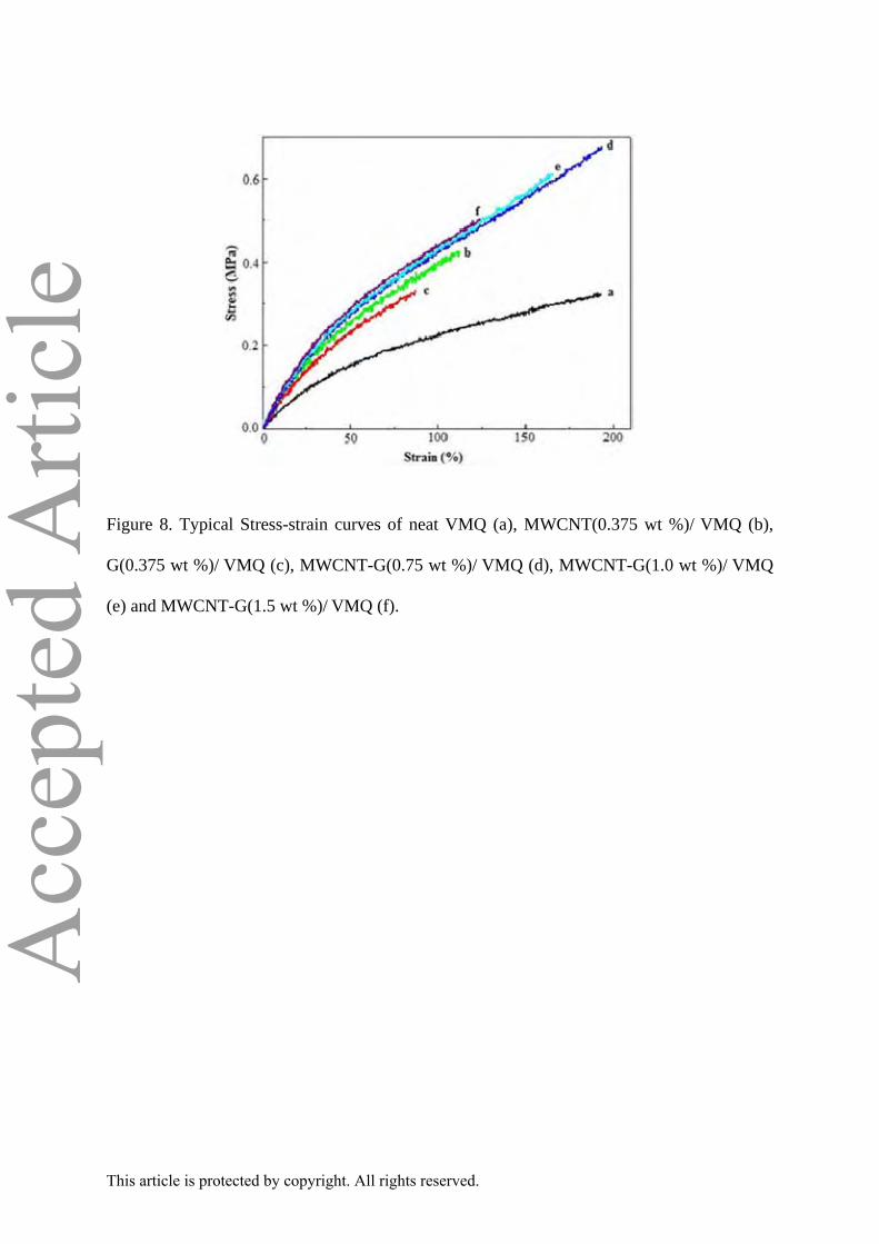
Fig. 8 shows the stress-strain plots of neat VMQ, MWCNT-G(0.75 wt %)/VMQ,
MWCNT-G(1.0 wt %)/VMQ and MWCNT-G(1.5 wt %)/VMQ nanocomposites. The stress-
strain plots of individually filled 0.375 wt % of MWCNT and G in VMQ are also included in
Fig. 8. The corresponding data related to the tensile strength (TS), elongation at break (EB)
and modulus at different % of strain of neat VMQ and its nanocomposites are presented in
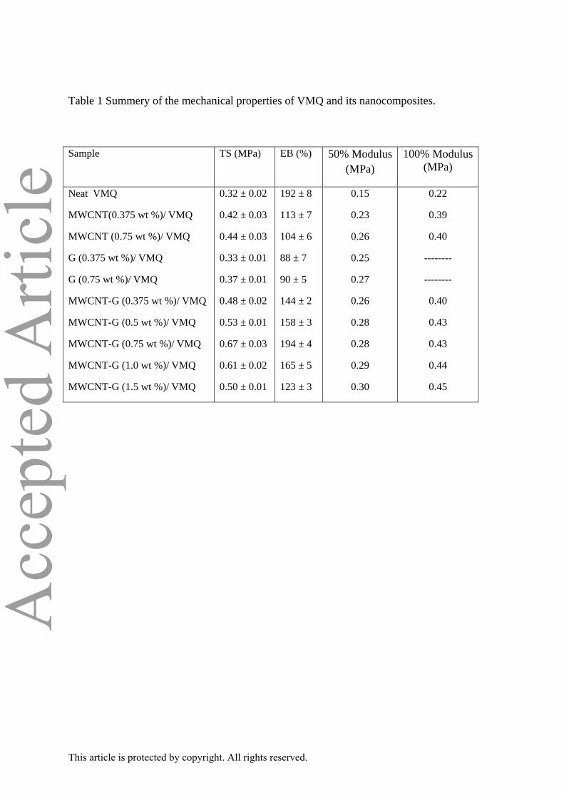
Table 1. It is noted that MWCNT-G(0.75 wt %)/VMQ exhibits maximum enhancement in TS
of 0.67 MPa compared to neat VMQ (0.32 MPa). When VMQ is individually filled with
0.375 wt % of MWCNT and G, TS follows the order: MWCNT/VMQ (TS: 0.42 MPa) >
G/VMQ (TS: 0.33 MPa). This clearly suggests that TS of MWCNT-G(0.75 wt %)/VMQ is
higher than the corresponding MWCNT or G nanocomposites. Table 1 also shows that the
modulus at 50 and 100% strain is increased in VMQ nanocomposites compared to neat
VMQ. It attains a maximum value in MWCNT-G/VMQ nanocomposites in all probability
due to the development of shear zones in nanocomposites under stress and strain conditions,63
or better dispersion of MWCNT-G leading to its enhanced interaction with VMQ.64 In
addition, EB of VMQ is considerably reduced when filled with 0.375 wt % loaded MWCNT
or G. Interestingly, such loss in flexibility of individually filled MWCNT and G
nanocomposites of VMQ has been recovered in case of MWCNT-G(0.75 wt %)/VMQ
nanocomposites. All these findings clearly demonstrate the synergistic effect of MWCNT-G
hybrid on the TS as well as EB of VMQ composite. This could be mainly attributed to the
homogeneous dispersion of 3D MWCNT-G hybrid filler in VMQ matrix. Alternatively, 3D
This article is protected by copyright. All rights reserved.
Page 13
Acc
epte
d A
rticl
ehybrid filler can become entangled with the polymer chains resulting better interaction
between MWCNT-G and VMQ matrix facilitating the efficient load transfer from polymer
matrix to nanofillers. It is also inferred from the data in Table 1 that modulus gradually
increases, while EB and tensile strength correspondingly decreases with increasing MWCNT-
G loadings (1.0 and 1.5 wt %) in VMQ. Such enhanced rigidity in composite is attributed to
the restriction effect of hybrid filler on the VMQ segments, similar results have also been
observed with previously reported CNT-graphene reinforced nanocomposites.39,40
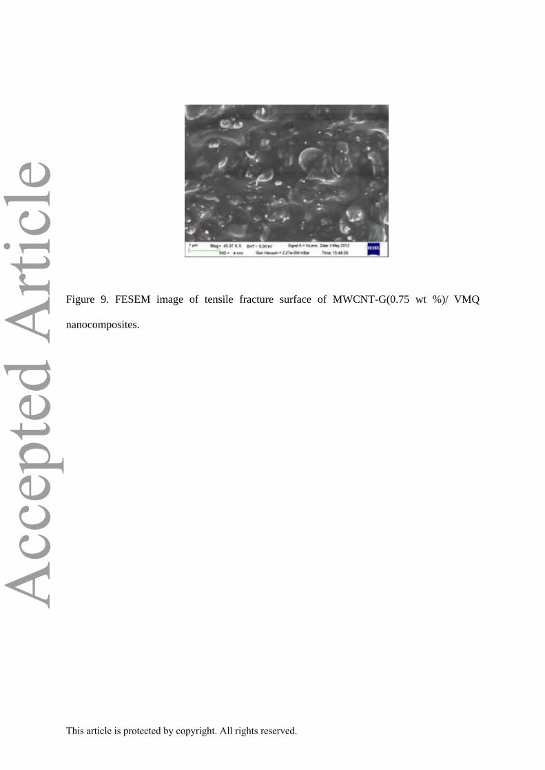
The improvements in mechanical properties of MWCNT-G filled VMQ
nanocomposites can also be correlated in terms of fracture behavior using FESEM analysis.
Fig. 9 displays the corresponding image of tensile fractured surface of MWCNT-G(0.75 wt
%)/VMQ. The image in Fig. 9 distinctly shows the homogeneous dispersion of hybrid filler
without involving any aggregation in the VMQ matrix. It is also observed that the hybrid
filled VMQ composite shows a rough fractured surface with bright spots, which are
developed due to the breaking of MWCNT rather than being just pulled out from the VMQ
matrix.65 These results indicate the presence of strong interfacial interaction between
MWCNT-G and VMQ matrix. All these facts are likely to contribute towards the
improvement in the mechanical properties of VMQ when reinforced with the hybrid filler.
Thermal properties of VMQ nanocomposites
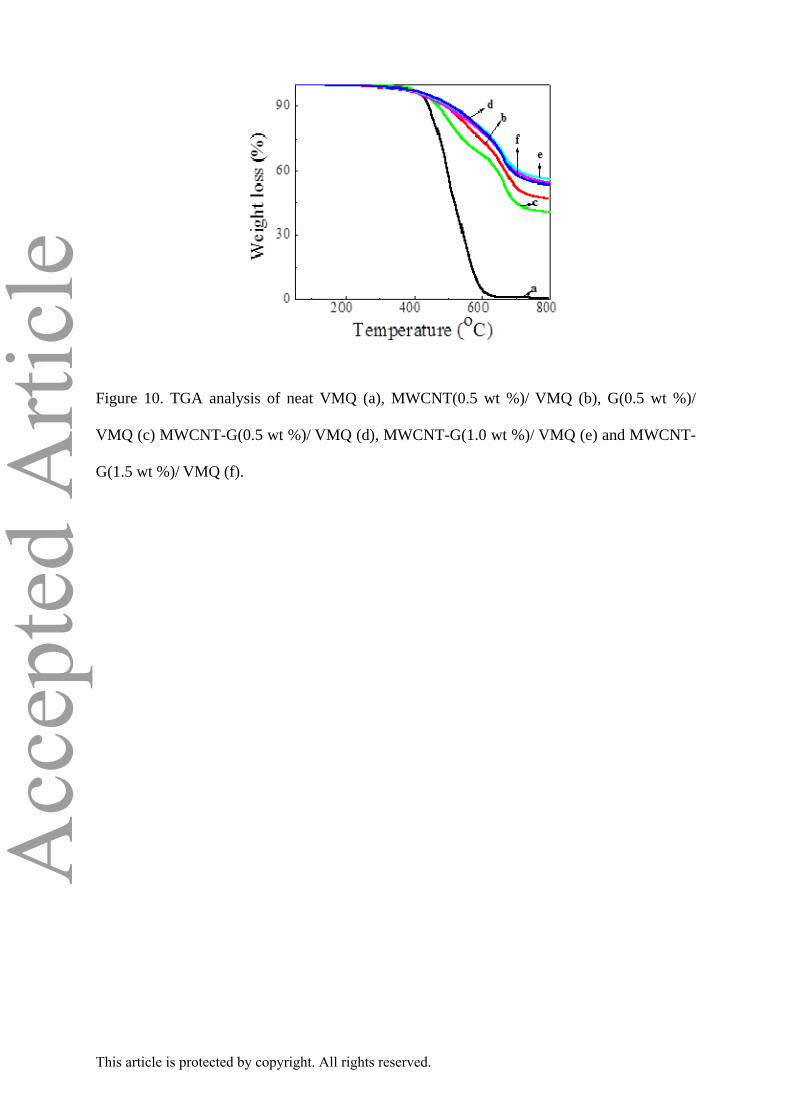
TG analysis has been performed to evaluate the thermal stability of neat VMQ
and its nanocomposites. Fig. 10 shows the thermogram of neat VMQ and its 0.5, 1.0 and 1.5
wt % MWCNT-G filled nanocomposites. Neat VMQ and its all nanocomposites exhibit two
steps degradation behaviour with different threshold. The first step degradation at about 410-
440 °C is regard as the depolymerisation of the siloxane chains and second step weight loss
due to the breakdown of the polymer backbone.66 In order to verify the synergistic effect of
hybrid filler on VMQ, thermograms of individually 0.5 wt % of MWCNT and G filled VMQ
This article is protected by copyright. All rights reserved.
Page 14
Acc
epte
d A
rticl
enanocomposites are also recorded and shown in Fig. 10. All the thermal data related to the
initial decomposition temperatures (T0), temperature corresponding to 25 % weight loss (T25)
and char residue at 800 °C of neat VMQ and its nanocomposites with MWCNT, G and
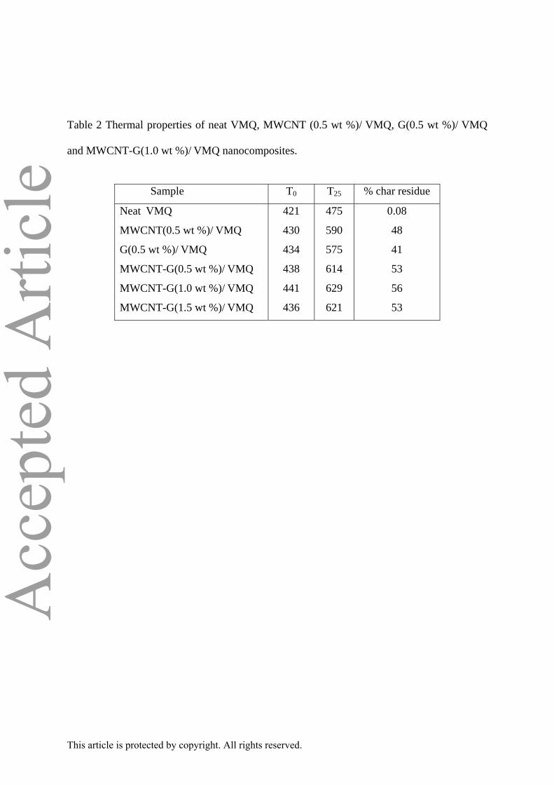
MWCNT-G are summarized in Table 2. It is evident from this that T0 and T25 of
MWCNT/VMQ, G/VMQ and MWCNT-G/VMQ are always higher than the neat VMQ.
However, MWCNT-G(1.0 wt %)/VMQ composite exhibits the maximum improvements in
T0 (441 °C) and T25 (629 °C) with respect to neat VMQ (T0: 421 °C, T25: 475 °C). Such
significant enhancement in T0 and T25 could be attributed to the hindering effect of the
confined geometry of 3D MWCNT-G hybrid structure on the diffusion of nitrogen and
volatile products throughout the composite materials by reducing the initiation of VMQ chain
scission. Alternatively, the possibility of the nano level dispersion of the hybrid filler and
enhanced interfacial interaction between VMQ and MWCNT-G suppressing the heat flux and
polymer backbone degradation also cannot be ruled out. It is also observed that the thermal
stability of hybrid filled VMQ nanocomposites is decreased with high hybrid (1.5 wt %)
content due to the aggregation tendency of the MWCNT-G in VMQ.67,68 The % of residue
left at 800 °C in VMQ and its composite in TGA suggest the following order in terms of
thermal stability: VMQ < G/VMQ < MWCNT/VMQ < MWCNT-G/VMQ. This is also in
agreement with our earlier findings deduced on the basis of the temperature referring to 25 %
weight loss (T25) of the samples in TG analysis. The maximum char residue in case of
MWCNT-G/VMQ nanocomposites could be attributed to the confined geometry and
interfacial interaction between MWCNT-G hybrid and VMQ. There is an obvious synergistic
effect of MWCNT-G hybrid on the retardance of thermal decomposition and enhancement of
carbonaceous char formation. On the other hand, the char residue of hybrid filled VMQ
nanocomposites is decreased with increasing filler loading. This is probably due to the
integrated effect of the interaction between the MWCNT-G and the polymer matrix.69
This article is protected by copyright. All rights reserved.
Page 15
Acc
epte
d A
rticl
eTherefore, the prepared MWCNT-G hybrid may find potential application as flame retardant
nano fillers.
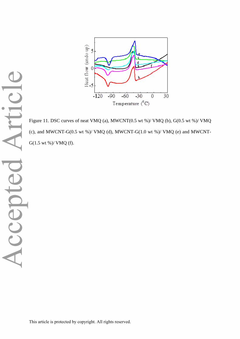
The effect of MWCNT, G and MWCNT-G loading on the crystallization and melting
behaviour of neat VMQ has been studied by DSC analysis and findings are presented in Fig.
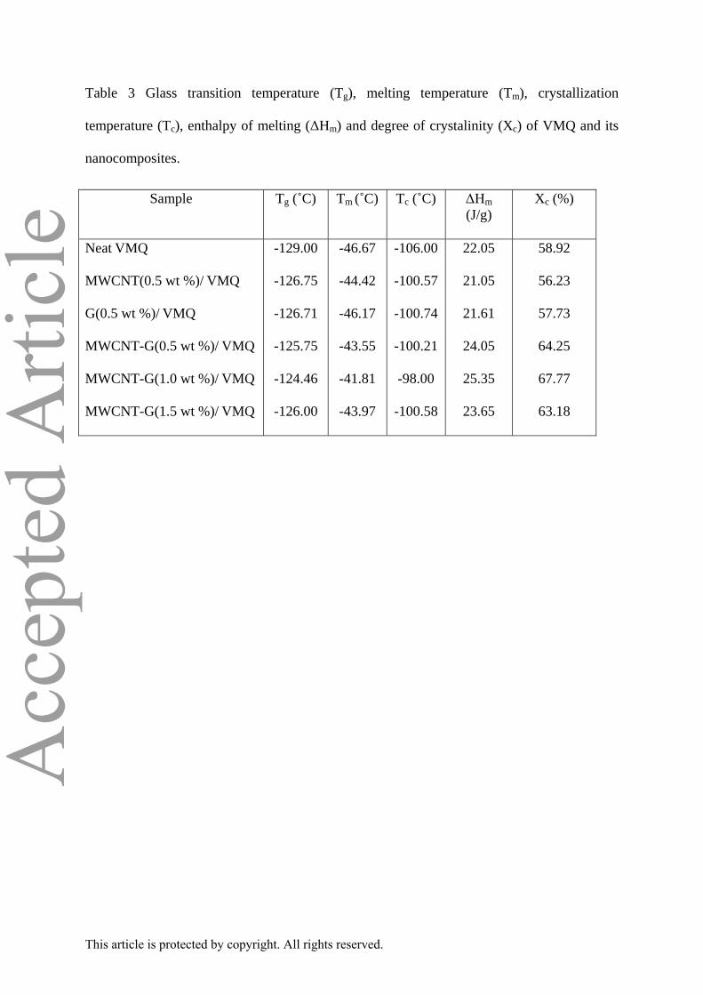
11 and all the corresponding data are summarized in Table 3. It is noted that the glass
transition temperature (Tg) follows the order: VMQ < MWCNT(0.5 wt G(0.5 wt %)/VMQ <
MWCNT-G(1.0 wt %)/VMQ nanocomposites. The maximum improvement in Tg of
MWCNT-G/VMQ composite could be attributed to the restricted mobility of the VMQ
chains in presence of 3D MWCNT-G hybrid filler. Fig. 11 also shows that the cold
crystallization peak (Tc) is absent in neat VMQ in all probability due to its complete
crystallization.70 Interestingly, the cold crystallization peak appeared at -100.57, -100.74, and
-98 °C in MWCNT(0.5 wt %)/VMQ, G(0.5 wt %)/VMQ and MWCNT-G(1.0 wt %)/VMQ
nanocomposites respectively. It is also noted that the sharpness of the peak is highest in
MWCNT-G filled VMQ possibly due to the homogeneous dispersion of hybrid filler in VMQ
and strong interfacial interaction between MWCNT-G and polymer segments. Though, DSC
plots show that the melting temperature (Tm) of VMQ is increased compared to neat VMQ by
2 and 5 °C in MWCNT/VMQ and MWCNT-G/VMQ respectively, Tm remains more or less
same in G/VMQ. The enthalpy of melting (ΔHm) of VMQ, MWCNT(0.5 wt %)/VMQ, G(0.5
wt %)/VMQ, MWCNT-G(1.0 wt %)/VMQ and MWCNT-G(1.5 wt %)/VMQ have also been
calculated from DSC analysis and found to be 22.05, 21.05, 21.61, 25.35 and 23.65 J/g
respectively. This is inevitable that both the melting temperature and ΔHm are higher in
MWCNT-G/VMQ compared to either neat VMQ or its individually filled MWCNT and
graphene nanocomposites. All these findings clearly demonstrate that 3D MWCNT-G hybrid
contributes the formation of more ordered VMQ by nucleation and growth processes. In
addition, the presence of the interfacial interaction between the hybrid and VMQ matrix
This article is protected by copyright. All rights reserved.
Page 16
Acc
epte
d A
rticl
edecreases the entanglement of the VMQ. As a result, MWCNT-G/VMQ composite exhibits
the increase in the crystallinity as well as melting temperature.71 However, the Tg, Tc, Tm and
degree of crystallinity of hybrid filled VMQ nanocomposites decreases with higher hybrid
(1.5 wt %) content. This may be ascribed to the fact that, dispersions of MWCNT-G become
poor at relatively higher hybrid content and this hinders to increase the crystallinity of
nanocomposites.72,73
Swelling properties of VMQ nanocomposites
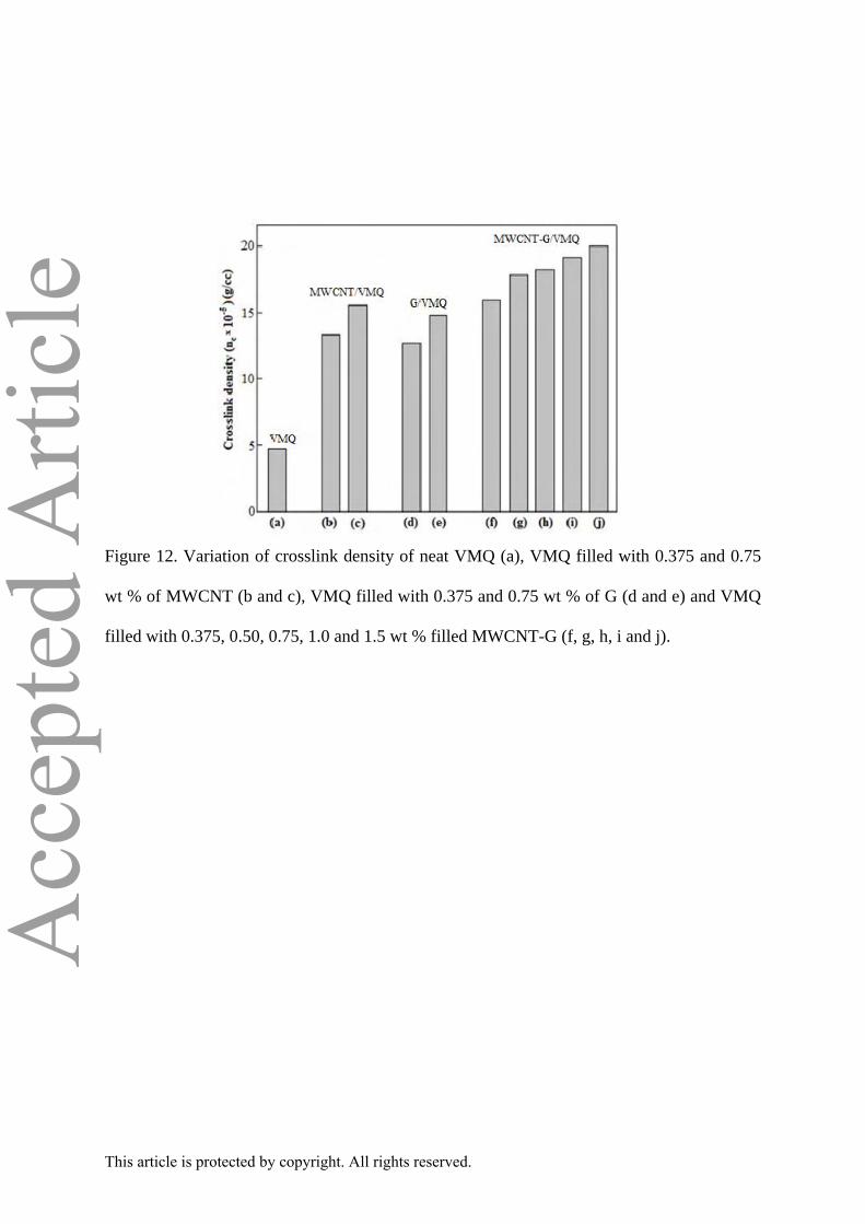
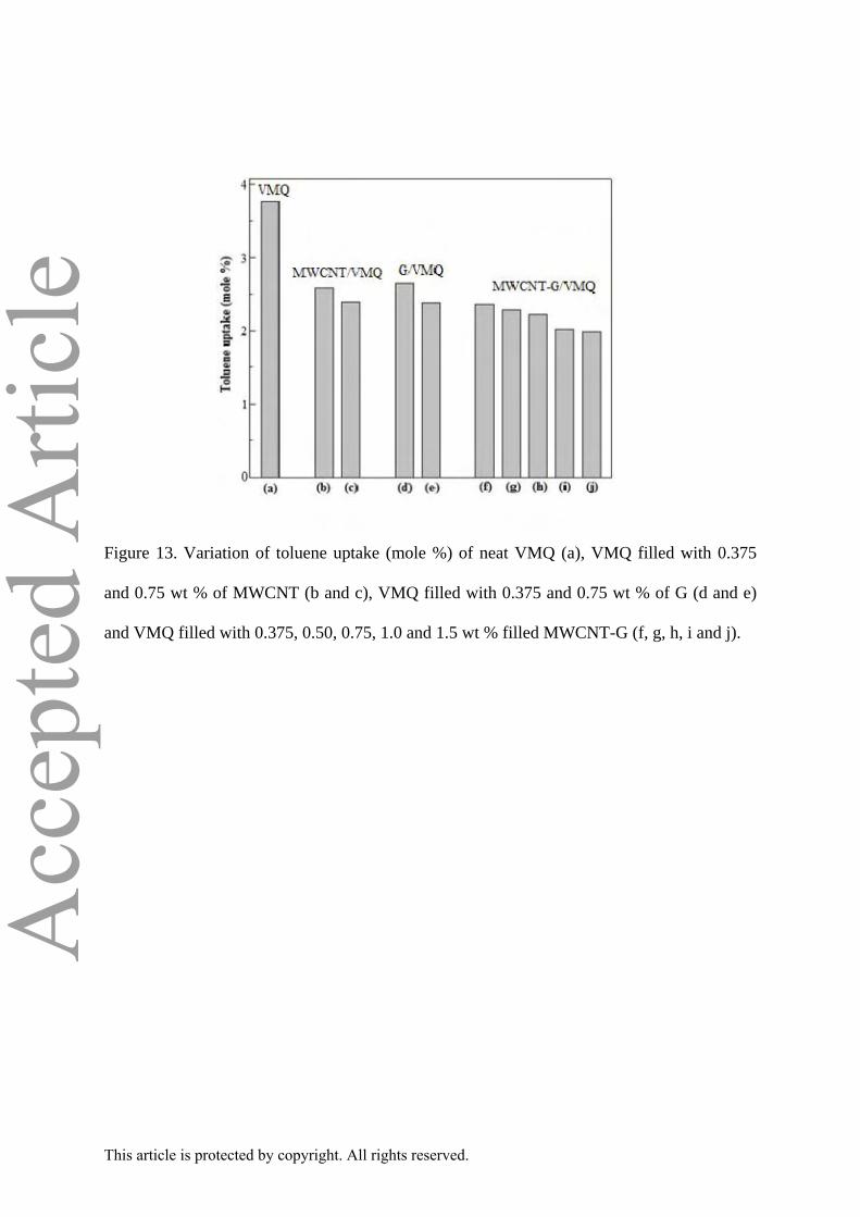
In order to evaluate the correlation between mechanical property and equilibrium
solvent uptake, swelling experiments have been carried out in toluene and the variation of
crosslink density (nc) and toluene uptake (mol %) of neat VMQ, MWCNT/VMQ, G/VMQ,
and MWCNT-G/VMQ nanocomposites are presented in Fig. 12 and 13 respectively. This
suggests that the crosslink densities of MWCNT-G/VMQ nanocomposites are always higher
compared to neat VMQ or individually MWCNT and graphene filled VMQ nanocomposites.
When, polymer blended with carbon nanotube or graphene, one can expect three networks:
the temporary polymer network formed by entanglements, the carbon nanotube (graphene)
network and a combined carbon nanotube (graphene)-polymer network. In all
probability,‘entanglements’ between the polymer chains and the nanotubes (grahene) could
form carbon nanotube–polymer or graphene-polymer network.74-76 As a consequence, the
crosslink density of carbon nanotube–polymer or graphene-polymer network is higher than
that of the entangled polymer network alone. The higher cross-link density of SWCNT/ VMQ
(and G/ VMQ) composite compared to pure SR could be attributed to the physical cross-
links/constraints of MWCNTs (and G) in the composites.77-79 In our case, MWCNT and G are
non functionalized suggesting the absence of any chemical bonding with SR. However, the
possibility of physical interactions between the filler and polymer due to the polymer
wrapping and/or coating of the filler can not be ruled out.80, 81 Alternatively, the sonication
This article is protected by copyright. All rights reserved.
Page 17
Acc
epte
d A
rticl
ecould lead the generation of free radicals in the polymer chains providing an additional
source of interaction with the filler.82,83
It is also inferred that crosslink density as well as Young’s modulus show increasing
trend with MWCNT-G loadings in VMQ. Fig. 13 shows that the solvent uptake ability of
MWCNT-G/VMQ nanocomposites is relatively less than neat VMQ, MWCNT/VMQ or
G/VMQ nanocomposites. This is probably due to the homogeneous dispersion and strong
interfacial interaction between MWCNT-G and VMQ polymer segments forming a bound
polymer. As a result, the solvent uptake is restricted from surface to bulk and the rigidity of
the polymer is also enhanced.84
CONCLUSIONS
The high performance MWCNT-G(0.75 wt %)/VMQ hybrid exhibits
significant improvements in tensile strength (110 %) and Young’s modulus (137 %), whereas
as elongation at break is retained compared to neat VMQ. It also shows the improvement in
glass transition temperature (4 °C), melting temperature (5 °C), crystallization temperature (8
°C) and thermal stability corresponding to 25 % weight loss (154 °C) in comparison neat
VMQ. Swelling measurements confirmed that the crosslink density and solvent resistance
property is also found to be maximum for hybrid nanocomposites. We also established that
the synergistic effect of MWCNT-G hybrid could account for such improvement in properties
of neat VMQ due to co dispersion of MWCNT and graphene nanosheets in VMQ matrix as
well as the strong interfacial interaction between 3D hybrid and VMQ segments.
ACKNOWLEDGMENTS
Author gratefully acknowledge Dr. Anubhav Saxena, GE India, Bangalore for
Baysilone U10, Baysilone U 430, Pt catalyst complex and Asbury Graphite Mills, Asbury, NJ
This article is protected by copyright. All rights reserved.
Page 18
Acc
epte
d A
rticl
efor providing natural graphite AKA SEFG 3777. Lastly, the financial help from CSIR and
DRDO, New Delhi, India is also greatly acknowledged.
Supporting Information Available
FTIR patterns of graphite, graphite oxide, graphene; WAXD patterns of graphite,
graphite oxide, graphene; TEM images of MWCNT-G (3:1) hybrid, MWCNT-G (1:3)
hybrid; WAXD patterns of MWCNT/ VMQ and graphene/ VMQ nanocomposites.
References
1 Iijima S, Nature 354:56-8 (1991)
2 Wong EW, Sheehan PE and Lieber CM, Science 277:1971–1975 (1997).
3 Tans SJ, Verschueren ARM and Dekker C. Nature (London) 393:49–52 (1998),
4 Poncharal P, Wang ZL, Ugarte D and Heer WAD, Science 283:1513–1516 (1999).
5 Novoselov KS, Geim AK, Morozov SV, Jiang D, Zhang Y and Dubonoset SV. et. al.
Science 306:666–669 (2004),
6 Geim A.K and Novoselov KS, Nat. Mater 6:183-191 (2007).
7 Fan X, Peng W, Li Y. Li X, Wang S, Zhang G and Zhang F, Adv Mater 20:4490-4493
(2008).
8 Rao CNR, Sood AK, Subrahmanyam KS and Govindaraj A, Angew Chem Int Ed 48:
7752-7777 (2009).
9 Yang W, Ratinac KR, Ringer SP, Thordarson P, Gooding JJ and Braet F, Angew
Chem Int Ed 49:2114-2138 (2010).
This article is protected by copyright. All rights reserved.
Page 19
Acc
epte
d A
rticl
e10 Liang J, Xu Y, Huang Y, Zhang L, Wang Y, Ma Y, Li F, Guo T and Chen Y, J Phys
Chem C 113:9921-9927 (2009).
11 Zhu YG, Cao GS, Xie J, Zhu T J and Zhao XB, Nanosci Nanotechnol Lett 4: 35-40
(2012).
12 Gruner G, J Mater Chem 16:3533-3539 (2006).
13 Cao Q, Hur S. H, Zhu Z.T, Sun Y G, Wang C J, Meitl M A, Shim M and Rogers J,
Adv Mater 18:387-394 (2008).
14 Coleman JN, Khan U, Blau WJ and Gun’ko YK, Carbon 44:1624-52 (2006).
15 Stankovich S, Dikin DA, Dommett GHB, Kohlhaas, KM, Zimney EJ, Stach EA, Piner
RD, Nguyen ST and Ruoff RS, Nature 442:282-286 (2006).
16 Sahoo NG, Rana S, Chao JW, Li L and Chan SH, Prog Polym Sci 35:837-867 (2010).
17 T. Kuila, et al, Prog Polym Sci 35:1350-1375 (2010).
18 Li D, Muller MB, Gilje S, Kaner RB and Wallace GG, Nat Nanotech 3:101-105
(2008).
19 Englert JM, Dotzer C, Yang G, Schmid M, Papp C, Gottfried JM, Steinrück HP,
Spiecker E, Hauke F and Hirsch A, Nat Chem 3:279-286 (2011).
20. Tchoul MN, Ford WT, Lolli G, Resasco DE and Arepall S, Chem Mater 19:5765-5772
(2007)
21. Paul RK, Ghazinejad, Penchev M, Lin J, Ozkan, Ozkan, Small 6:2309-2313 (2010).
22. Huang L, Wu B, Yu G, Liu Y, J Mater Chem 21:919-929 (2011).
23. Mengting Chen, Tao Tao, Ling Zhang, Wei Gao and Chunzhong Li, Chem Commun
49:1612-1614 (2013).
24 Young Soo Yun et al. Synt Met 161:2460-2465 (2011).
25 Seunghee Woo et al, Electrochimica Acta 59:509-514 (2012),
This article is protected by copyright. All rights reserved.
Page 20
Acc
epte
d A
rticl
e26 Liu Y, Liu Y, Feng H, Wu Y, Joshi L and Zeng X, Biosens. Bioelectron 35:63-68
(2012).
27 Gil Woo Jeon, Young Gyu Jong, J Mater Sci 48: 4041-4049 (2013).
28 Wang Z, Meng X, Li J, Du X, Li S, Jiang Z, Tang T, J Phys Chem C 113:8058-8064 (2009).
29 Kim YS, Kumar K, Fisher FT and Yang EH, Nanotechnology 23:015301-7 (2012).
30 Peng L, Feng Y, Lv P, Lei D, Shen Y, Li Y and Feng W, J Phys Chem C
116:4970−4978 (2012).
31 Yen MY, Hsiao MC, Liao SH, Liu PI, Tsai HM,Ma CCM, Pu NW and Ger MD, Carbon
49:3597-3606(2011).
32 Georgakilas V, Bourlinos A, Gournis D, Tsoufis T, Trapalis C, Mateo-Alonso A,
Prato M, J Am Chem Soc 130: 8733-8740 (2008).
33. Kartick B, Srivastava SK, Chem Commun 49: 1823-1825 (2013).
34. Hu H, Zhao L, Liu J, Liu Y, Cheng J, Luo J, Liang Y, Tao Y, Wang X and Zhao J,
Polymer 41:3378-338 (2012)
35 Yu D and Dai L, J Phys Chem Lett 1:467-470 (2010).
36 Nguyen DD, Tai NH, Chen SY and Chueh YL, Nanoscale 4:632-638 (2012).
37 Patole AS, Patole SP, Jung SY, Yoo JB, An JH and Kim TH, Eur Polym J 48:252-259
(2012).
38 Yang SY, Lin WN, Huang YL, Tien HW, Wang JY, Ma CCM, Li SM and Wang YS,
Carbon 49:793-803 (2011).
39 Liu YT, Dang M, Xie XM, Wang ZF and Ye XY, J Mater Chem 21:18723-29
(2011).
40 Zhang C, Huang S, Tjiu WW, Fana W and Liu T, J Mater Chem 22:2427-34 (2012)
This article is protected by copyright. All rights reserved.
Page 21
Acc
epte
d A
rticl
e41 Bhowmick AK and Stephens HL, Handbook of elastomers, Marcel Dekker, Inc. New
York 2001
42 LeBaron PC and Pinnavaia TJ, Chem Mater 13:3760-3765 (2001).
43. Dewimille L, Bresson B and Bokobza L, Polymer 46:4135-43 (2005).
44 Verdejo R, Saiz-Arroyo C, Carretero-Gonzalez J, Barroso-Bujans F, Rodriguez-Perez
MA and Lopez-Manchado MA, Eur Polym J 44:2790-97 (2008).
45 Pradhan B, Srivastava SK, Bhowmick AK and Saxena A, Polym Int 61:458-65
(2012).
46 Luo X, Chung DDL, Composites: Part B 30:227–231 (1999).
47 Jou WS, Cheng HZ, Hsu CF, J Electronic Mater 35:462–470 (2006).
48 Hummers JR, William S and Oreffeman RE, J Am Chem Soc 80:1339 (1958).
49 Flory PJ and Rehner JH, J Chem Phys 11:521-30 (1943).
50 Choi EY, Han TH, Hong J, Kim, JE, Lee SH, Kima HW and Kim SO, J Mater Chem
20:1907–1912 (2010).
51 Xu Y, Bai H, Lu G, Li C and Shi G, J Am Chem Soc 130:5856-5857 (2008).
52 Li D, Muller MB, Gilje S, Kaner RB and Wallace GG, Nat Nanotechnol 3:101-105
(2008).
53 Titelman GI, Gelman V, Bron S, Khalfin RL, Cohen Y and Peled HB, Carbon
43:641-649 (2005).
54 Wang G, Yang J, Park J, Gou X, Wang B, Liu H and Yao J, J Phys Chem C
112:8192-8195 (2008).
55 Liu J, Shao M, Chen X, Yu W, Liu X and Qian Y, J Am Chem Soc 125:8088-89
(2003).
56 Dong X, Xing G, Chan-Park MB, Shi W, Xiao N, Wang J, Yan Q, Sum TC, Huang W
and Chen P, Carbon 49: 5071-5078 (2011).
This article is protected by copyright. All rights reserved.
Page 22
Acc
epte
d A
rticl
e57 Kim J, Cote LJ, Kim F, Yuan W, Shull KR and Huang J, J Am Chem Soc 132:8180-
86 (2010).
58 Mattevi C, Eda G, Agnoli S, Miller S, Mkhoyan KA, Celik O, Mastrogiovanni D,
Granozzi G, Garfunkel E and Chhowalla M, Adv Funct Mater 19:2577-2583 (2009).
59 McAllister MJ, Li JL, Adamson DH, Schniepp HC, Abdala AA, Liu J, Herrera-
Alonso M, Milius DL, Car R, Prud'homme RK and Aksay IA, Chem Mater 19:4396-
4404 (2007).
60 Fan ZJ, Kai W, Yan J, Wei T, Zhi LJ, Feng J, Ren Y, Song L and Wei F, ACS Nano
5:191-198 (2011).
61 Albouy PA, Polymer 41:3083-3086 (2000).
62 Sahoo NG, Cheng HKF, Caia J, Li L, Chan SH, Zhao J and Yu S, Mater Chem Phys
117:313-320 (2009).
63 Selvin TP, Seno J, Murukan B, Santhosh AA, Sabu T, Weimin Y, Sri B, Polym
Compos 1011-1019 (2010).
64 Acharya H, Srivastava SK. and Bhowmick AK, Compos Sci Technol 67:2807–2816
(2007).,
65 Jiang MJ, Dang ZM and Xu HP, Eur Polym J 43:4924-4930 (2007).
66 Camino G, Lomakin SM, Lageard M, Polymer 43:2011-2015 (2002).
67 Chen W and Qu B, J Mater Chem 14:1705-1710 (2004).
68 Ray SS and Okamoto M, Prog Polym Sci 28:1539-1641 (2003).
69 Wang J, Chen Y and Jin Q, Macromol Chem Phys 206:2512-2520 (2005).
70 Dollase T, Wilhelm M, Spiess HW, Yagen Y, Yerushalmi-Rozen R, and Gottlieb M,
Interface Sci 11:199-209 (2003)
71 Zhang C, Tjiu WW, Liu T, Lui WY, Phang IY and Zhang WD, J Phys Chem B
115:3392-3399 (2011).
This article is protected by copyright. All rights reserved.
Page 23
Acc
epte
d A
rticl
e72 Prashantha K, Lacrampe MF, Krawczak P, eXPRESS Polym Lett 5:295-307 (2011).
73 Samir MASA, Alloin F, Sanchez JY and Dufresne A, Polymer 45:4149-4157 (2004).
74 Po¨tschke P, Abdel-Goad M, Alig I, Dudkin S and Lellinger D, Polymer 45: 8863–8870
(2004)
75 Bhattacharyya S, Sinturel C, Bahloul O, Saboungi ML, Thomas S and Salvetat JP, Carbon
46: 1037–1045(2008)
76 FrO¨hlich J, Niedermeir W and Luginsland HD, Comp Appl Sci Manuf. 36: 449-460
(2005).
77 Gerson AL, Bruck HA, Hopkins AR and Segal KN, Composites Part A 41:729-736
(2010).
78 Tonpheng B, Yu J, Andersson BM and Andersson O. Macromolecules 43: 7680−7688
(2010).
79 Gkikas G, Barkoula NM and Paipetis AS. Composites Part B 43: 2697–2705 (2012).
80 Qu M, Deng F, Kalkhoran SM, Gouldstone A, Robisson A and Van Vliet KJ, Soft Matter
7: 1066−1077 (2011).
81 Ismail H, Pasbakhsh P, Ahmad Fauzi MN, Abu Bakar A, Polymer Testing 27: 841–850
(2008).
82 Yu J, Tonpheng B, Gro¨bner G, and Andersson O, Macromolecules 45: 2841-2849 (2012).
83 Verge P, Peeterbroeck S, Bonnaud L and Dubois P, Compos Sci Technol 70: 1453−1459
(2010).
84 Huang JC, Zhu ZK, Yin J, Qian XF and Sun YY, Polymer 42:873-877 (2001).
This article is protected by copyright. All rights reserved.
Page 24
Acc
epte
d A
rticl
eA. Caption to Schemes
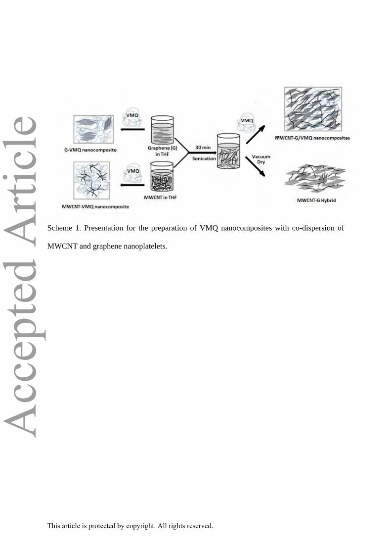
Scheme 1. Presentation for the preparation of VMQ nanocomposites with co-dispersion of
MWCNT and graphene nanoplatelets.
B. Caption to Figures
Figure 1. WAXD patterns of MWCNT (a), G (b), MWCNT-G (3:1) (c), MWCNT-G (1:3)
(d) and MWCNT-G (1:1) (e).
Figure 2. WAXD profiles for 002 reflection of G (a), MWCNT-G (3:1) (b), MWCNT-G
(1:3) (c) and MWCNT-G (1:1) (d).
Figure 3. TEM images of MWCNT (a), G (b) and MWCNT-G (1:1) hybrid (c). (The inset
shows the corresponding SAED pattern of the fillers).
Figure 4. Digital images showing room temperature dispersion of MWCNT (a), G (b),
MWCNT-G (3:1) in THF (c), MWCNT-G (1:1) in THF (d), MWCNT-G (1:3) in THF (e),
(The photographs were taken after 1 day of storage at room temperature).
Figure 5. TGA curves of MWCNT (a), G (b) and MWCNT-G (1:1) (c).
Figure 6. TEM image of MWCNT(0.375 wt %)/ VMQ (a), G(0.375 wt %)/ VMQ (b),
MWCNT-G(0.375 wt %)/ VMQ (c), MWCNT-G(0.75 wt %)/ VMQ (d) and MWCNT-G(1.5
wt %)/ VMQ (e).
Figure 7. WAXD patterns of VMQ (a), MWCNT-G(0.375 wt %)/ VMQ (b), MWCNT-G(0.5
wt %)/ VMQ (c), MWCNT-G(0.75 wt %)/VMQ (d), MWCNT-G(1.0 wt %)/ VMQ (e) and
MWCNT-G(1.5 wt %)/ VMQ (f).
This article is protected by copyright. All rights reserved.
Page 25
Acc
epte
d A
rticl
eFigure 8. Typical Stress-strain curves of neat VMQ (a), MWCNT(0.375 wt %)/VMQ (b),
G(0.375 wt %)/VMQ (c), MWCNT-G(0.75 wt %)/VMQ (d), MWCNT-G(1.0 wt %)/VMQ
(e) and MWCNT-G(1.5 wt %)/ VMQ (f).
Figure 9. FESEM image of tensile fracture surface of MWCNT-G(0.75 wt %)/ VMQ
nanocomposites.
Figure 10. TGA analysis of neat VMQ (a), MWCNT(0.5 wt %)/ VMQ (b), G(0.5 wt %)/
VMQ (c) MWCNT-G(0.5 wt %)/ VMQ (d), MWCNT-G(1.0 wt %)/ VMQ (e) and MWCNT-
G(1.5 wt %)/ VMQ (f).
Figure 11. DSC curves of neat VMQ (a), MWCNT(0.5 wt %)/ VMQ (b), G(0.5 wt %)/ VMQ
(c), and MWCNT-G(0.5 wt %)/ VMQ (d), MWCNT-G(1.0 wt %)/ VMQ (e) and MWCNT-
G(1.5 wt %)/ VMQ (f).
Figure 12. Variation of crosslink density of neat VMQ (a), VMQ filled with 0.375 and 0.75
wt % of MWCNT (b and c), VMQ filled with 0.375 and 0.75 wt % of G (d and e) and VMQ
filled with 0.375, 0.50, 0.75, 1.0 and 1.5 wt % filled MWCNT-G (f, g, h, i and j).
Figure 13. Variation of toluene uptake (mole %) of neat VMQ (a), VMQ filled with 0.375
and 0.75 wt % of MWCNT (b and c), VMQ filled with 0.375 and 0.75 wt % of G (d and e)
and VMQ filled with 0.375, 0.50, 0.75, 1.0 and 1.5 wt % filled MWCNT-G (f, g, h, i and j).
This article is protected by copyright. All rights reserved.
Page 26
Acc
epte
d A
rticl
eC. Caption to the Tables
Table 1 Summery of the mechanical properties of VMQ and its nanocomposites.
Table 2 Thermal properties of neat VMQ, MWCNT (0.5 wt %)/ VMQ, G(0.5 wt %)/ VMQ
and MWCNT-G(1.0 wt %)/ VMQ nanocomposites.
Table 3 Glass transition temperature (Tg), melting temperature (Tm), crystallization
temperature (Tc), enthalpy of melting (ΔHm) and degree of crystalinity (Xc) of VMQ and its
nanocomposites.
This article is protected by copyright. All rights reserved.
Page 27
Acc
epte
d A
rticl
e
Scheme 1. Presentation for the preparation of VMQ nanocomposites with co-dispersion of
MWCNT and graphene nanoplatelets.
This article is protected by copyright. All rights reserved.
Page 28
Acc
epte
d A
rticl
e
Table 1 Summery of the mechanical properties of VMQ and its nanocomposites.
Sample TS (MPa) EB (%) 50% Modulus (MPa)
100% Modulus (MPa)
Neat VMQ
MWCNT(0.375 wt %)/ VMQ
MWCNT (0.75 wt %)/ VMQ
G (0.375 wt %)/ VMQ
G (0.75 wt %)/ VMQ
MWCNT-G (0.375 wt %)/ VMQ
MWCNT-G (0.5 wt %)/ VMQ
MWCNT-G (0.75 wt %)/ VMQ
MWCNT-G (1.0 wt %)/ VMQ
MWCNT-G (1.5 wt %)/ VMQ
0.32 ± 0.02
0.42 ± 0.03
0.44 ± 0.03
0.33 ± 0.01
0.37 ± 0.01
0.48 ± 0.02
0.53 ± 0.01
0.67 ± 0.03
0.61 ± 0.02
0.50 ± 0.01
192 ± 8
113 ± 7
104 ± 6
88 ± 7
90 ± 5
144 ± 2
158 ± 3
194 ± 4
165 ± 5
123 ± 3
0.15
0.23
0.26
0.25
0.27
0.26
0.28
0.28
0.29
0.30
0.22
0.39
0.40
--------
--------
0.40
0.43
0.43
0.44
0.45
This article is protected by copyright. All rights reserved.
Page 29
Acc
epte
d A
rticl
e
Table 2 Thermal properties of neat VMQ, MWCNT (0.5 wt %)/ VMQ, G(0.5 wt %)/ VMQ
and MWCNT-G(1.0 wt %)/ VMQ nanocomposites.
Sample T0 T25 % char residue
Neat VMQ
MWCNT(0.5 wt %)/ VMQ
G(0.5 wt %)/ VMQ
MWCNT-G(0.5 wt %)/ VMQ
MWCNT-G(1.0 wt %)/ VMQ
MWCNT-G(1.5 wt %)/ VMQ
421
430
434
438
441
436
475
590
575
614
629
621
0.08
48
41
53
56
53
This article is protected by copyright. All rights reserved.
Page 30
Acc
epte
d A
rticl
eTable 3 Glass transition temperature (Tg), melting temperature (Tm), crystallization
temperature (Tc), enthalpy of melting (ΔHm) and degree of crystalinity (Xc) of VMQ and its
nanocomposites.
Sample
Tg (˚C)
Tm (˚C)
Tc (˚C)
ΔHm (J/g)
Xc (%)
Neat VMQ
MWCNT(0.5 wt %)/ VMQ
G(0.5 wt %)/ VMQ
MWCNT-G(0.5 wt %)/ VMQ
MWCNT-G(1.0 wt %)/ VMQ
MWCNT-G(1.5 wt %)/ VMQ
-129.00
-126.75
-126.71
-125.75
-124.46
-126.00
-46.67
-44.42
-46.17
-43.55
-41.81
-43.97
-106.00
-100.57
-100.74
-100.21
-98.00
-100.58
22.05
21.05
21.61
24.05
25.35
23.65
58.92
56.23
57.73
64.25
67.77
63.18
This article is protected by copyright. All rights reserved.
Page 31
Acc
epte
d A
rticl
e
Figure 1. WAXD patterns of MWCNT (a), G (b), MWCNT-G (3:1) (c), MWCNT-G (1:3) (d)
and MWCNT-G (1:1) (e).
This article is protected by copyright. All rights reserved.
Page 32
Acc
epte
d A
rticl
e
Figure 2. WAXD profiles for 002 reflection of G (a), MWCNT-G (3:1) (b), MWCNT-G (1:3)
(c) and MWCNT-G (1:1) (d).
This article is protected by copyright. All rights reserved.
Page 33
Acc
epte
d A
rticl
e
Figure 3. TEM images of MWCNT (a), G (b) and MWCNT-G (1:1) hybrid (c). (The inset
shows the corresponding SAED pattern of the fillers).
This article is protected by copyright. All rights reserved.
Page 34
Acc
epte
d A
rticl
e
Figure 4. Digital images showing room temperature dispersion of MWCNT (a), G (b),
MWCNT-G (3:1) in THF (c), MWCNT-G (1:1) in THF (d), MWCNT-G (1:3) in THF (e),
(The photographs were taken after 1 day of storage at room temperature).
This article is protected by copyright. All rights reserved.
Page 35
Acc
epte
d A
rticl
e
Figure 5. TGA curves of MWCNT (a), G (b) and MWCNT-G (1:1) (c).
This article is protected by copyright. All rights reserved.
Page 36
Figure 6. TEM image of MWCNT(0.375 wt %)/ VMQ (a), G(0.375 wt %)/ VMQ (b),
MWCNT-G(0.375 wt %)/ VMQ (c), MWCNT-G(0.75 wt %)/ VMQ (d) and MWCNT-G(1.5
wt %)/ VMQ (e).
d e
b a c
This article is protected by copyright. All rights reserved.
Page 37
Acc
epte
d A
rticl
e
Figure 7. WAXD patterns of VMQ (a), MWCNT-G(0.375 wt %)/ VMQ (b), MWCNT-G(0.5
wt %)/ VMQ (c), MWCNT-G(0.75 wt %)/ VMQ (d), MWCNT-G(1.0 wt %)/ VMQ (e) and
MWCNT-G(1.5 wt %)/ VMQ (f).
This article is protected by copyright. All rights reserved.
Page 38
Acc
epte
d A
rticl
e
Figure 8. Typical Stress-strain curves of neat VMQ (a), MWCNT(0.375 wt %)/ VMQ (b),
G(0.375 wt %)/ VMQ (c), MWCNT-G(0.75 wt %)/ VMQ (d), MWCNT-G(1.0 wt %)/ VMQ
(e) and MWCNT-G(1.5 wt %)/ VMQ (f).
This article is protected by copyright. All rights reserved.
Page 39
Acc
epte
d A
rticl
e
Figure 9. FESEM image of tensile fracture surface of MWCNT-G(0.75 wt %)/ VMQ
nanocomposites.
This article is protected by copyright. All rights reserved.
Page 40
Acc
epte
d A
rticl
e
Figure 10. TGA analysis of neat VMQ (a), MWCNT(0.5 wt %)/ VMQ (b), G(0.5 wt %)/
VMQ (c) MWCNT-G(0.5 wt %)/ VMQ (d), MWCNT-G(1.0 wt %)/ VMQ (e) and MWCNT-
G(1.5 wt %)/ VMQ (f).
This article is protected by copyright. All rights reserved.
Page 41
Acc
epte
d A
rticl
e
Figure 11. DSC curves of neat VMQ (a), MWCNT(0.5 wt %)/ VMQ (b), G(0.5 wt %)/ VMQ
(c), and MWCNT-G(0.5 wt %)/ VMQ (d), MWCNT-G(1.0 wt %)/ VMQ (e) and MWCNT-
G(1.5 wt %)/ VMQ (f).
This article is protected by copyright. All rights reserved.
Page 42
Acc
epte
d A
rticl
e
Figure 12. Variation of crosslink density of neat VMQ (a), VMQ filled with 0.375 and 0.75
wt % of MWCNT (b and c), VMQ filled with 0.375 and 0.75 wt % of G (d and e) and VMQ
filled with 0.375, 0.50, 0.75, 1.0 and 1.5 wt % filled MWCNT-G (f, g, h, i and j).
This article is protected by copyright. All rights reserved.
Page 43
Acc
epte
d A
rticl
e
Figure 13. Variation of toluene uptake (mole %) of neat VMQ (a), VMQ filled with 0.375
and 0.75 wt % of MWCNT (b and c), VMQ filled with 0.375 and 0.75 wt % of G (d and e)
and VMQ filled with 0.375, 0.50, 0.75, 1.0 and 1.5 wt % filled MWCNT-G (f, g, h, i and j).
This article is protected by copyright. All rights reserved.