24
ACN# 088 609 661 Q-Logic Controller Synergy TRU-Balance Power Tilt BASIC OPERATION INSTRUCTIONS Q-Logic Controller ACN# 088 609 661 TM TM TM TM TM

ACN# 088 609 661
Q-Logic ControllerSynergy TRU-BalancePower Tilt
BASIC OPERATION INSTRUCTIONS
Q-LogicController
ACN# 088 609 661
TMTMTMTMTM
2 Basic Operation Instructions
Q-Logic Controller www.quantumrehab.com
INFORMATION LABELING
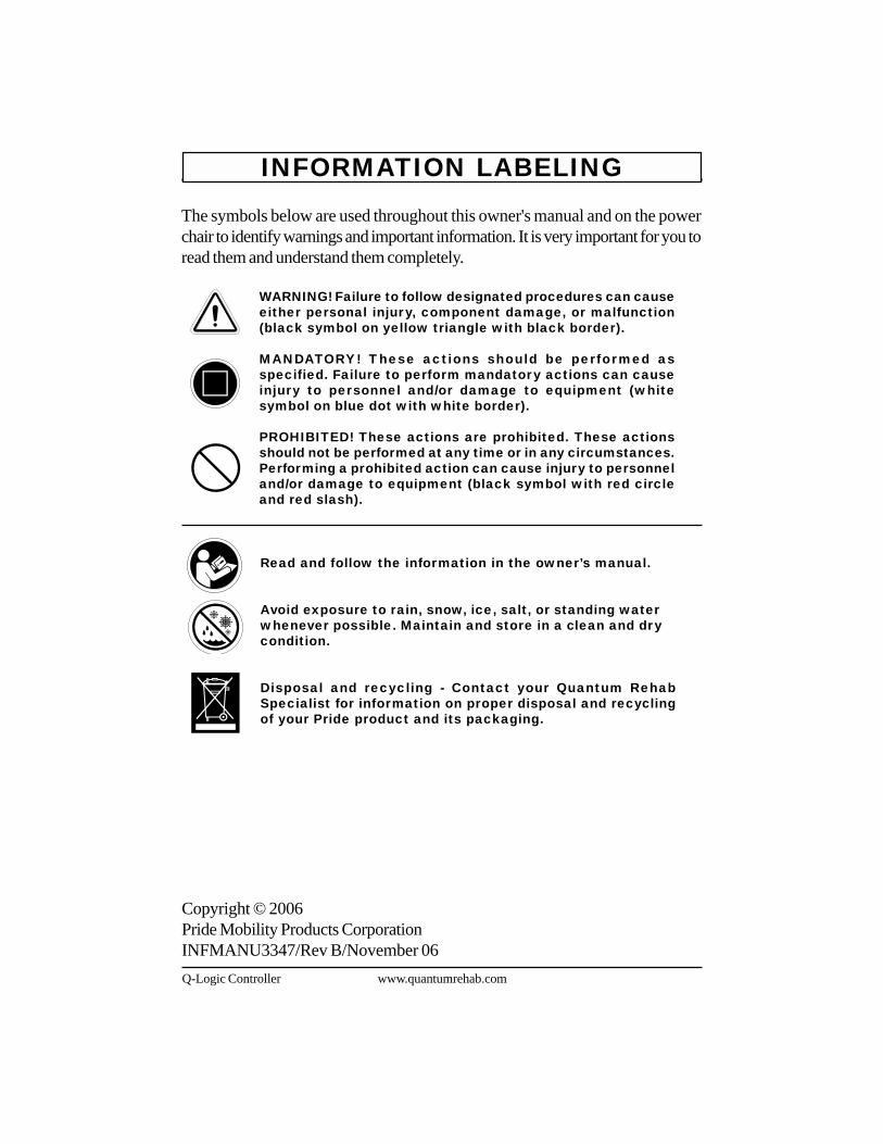
Read and follow the information in the owner’s manual.
Avoid exposure to rain, snow, ice, salt, or standing waterwhenever possible. Maintain and store in a clean and drycondition.
Disposal and recycling - Contact your Quantum RehabSpecialist for information on proper disposal and recyclingof your Pride product and its packaging.
Copyright © 2006Pride Mobility Products CorporationINFMANU3347/Rev B/November 06
The symbols below are used throughout this owner's manual and on the powerchair to identify warnings and important information. It is very important for you toread them and understand them completely.
WARNING! Failure to follow designated procedures can causeeither personal injury, component damage, or malfunction(black symbol on yellow triangle with black border).
MANDATORY! These actions should be performed asspecified. Failure to perform mandatory actions can causeinjury to personnel and/or damage to equipment (whitesymbol on blue dot with white border).
PROHIBITED! These actions are prohibited. These actionsshould not be performed at any time or in any circumstances.Performing a prohibited action can cause injury to personneland/or damage to equipment (black symbol with red circleand red slash).

Basic Operation Instructions 3
www.quantumrehab.com Q-Logic Controller
TABLE OF CONTENTS
INTRODUCTION ................................................................................. 4
Q-LOGIC CONTROLLER ................................................................. 6
PRECAUTIONARY GUIDELINES ................................................. 6
OPERATING THE Q-LOGIC CONTROLLER .......................... 12Joystick Control ............................................................................. 12Speed Adjustment Knob ............................................................ 12Keypad ................................................................................................. 12LCD Screen ....................................................................................... 13Drive Screen ..................................................................................... 13Drive Profile Selection ................................................................ 14Actuator Adjustment (Seat Screen) .................................... 14Main Menu ......................................................................................... 15Auxiliary (Aux) Menu .................................................................... 16Standby Select Menu .................................................................. 16Attendant Control/Stand Alone Joystick .......................... 17Enhanced Display .......................................................................... 18
SLEEP MODE .................................................................................... 19
THERMAL ROLLBACK .................................................................. 19
BATTERY CONDITION METER ................................................. 19
Q-LOGIC ERROR CODES .............................................................. 20
CARE AND MAINTENANCE ........................................................ 21
WARRANTY ........................................................................................ 21

4 Basic Operation Instructions
Q-Logic Controller www.quantumrehab.com
INTRODUCTIONWELCOME to Quantum Rehab, a division of Pride Mobility Products Corporation(Pride). The product you have purchased combines state-of-the-art componentswith safety, comfort, and styling in mind. We are confident that the design featureswill provide you with the conveniences you expect during your daily activities.Understanding how to safely operate and care for this product should bring youyears of trouble free operations and service.
Read and follow all instructions, warnings, and notes in this manual and all otheraccompanying literature before attempting to operate this product for the firsttime. In addition, your safety depends upon you, as well as your provider, caretaker,or healthcare professional in using good judgement.
This manual is to be used in addition to the power base owner’s manual that came withyour power chair. If there is any information in this manual which you do not understand,or if you require additional assistance for setup or operation, please contact yourQuantum Rehab Specialist. Failure to follow the instructions, warnings, andnotes in this manual and those located on your Pride product can result inpersonal injury and/or product damage and will void Pride’s product warranty.
PURCHASER’S AGREEMENTBy accepting delivery of this product, you promise that you will not change, alter,or modify this product or remove or render inoperable or unsafe any guards,shields, or other safety features of this product; fail, refuse, or neglect to install anyretrofit kits from time to time provided by Pride to enhance or preserve the safeuse of this product.
INFORMATION EXCHANGEWe want to hear your questions, comments, and suggestions about this manual.We would also like to hear about the safety and reliability of your new Prideproduct, and about the service you received from your Quantum Rehab Specialist.Please notify us of any change of address, so we can keep you apprised of importantinformation about safety, new products, and new options that can increase yourability to use and enjoy your Pride product.

Basic Operation Instructions 5
www.quantumrehab.com Q-Logic Controller
NOTE: If you ever lose or misplace your product registration card or yourcopy of this manual, contact us and we will be glad to send you a new oneimmediately.
My Quantum Rehab Specialist Is:
Name: _____________________________________________________
Address:____________________________________________________
Phone Number: ______________________________________________
Purchase Date: _______________________________________________

6 Basic Operation Instructions
Q-Logic Controller www.quantumrehab.com
Q-LOGIC CONTROLLERThe Q-Logic Controller is a fully-programmable, modular electronic controller systemthat allows you to operate your power chair. The Q-Logic has several input devicesavailable which operate through a power module. The hand control will primarily bediscussed in this manual, along with references to the Enhanced Display, Stand AloneJoystick, and Attendant Control. Additional input devices and programmers are alsoavailable for the Q-Logic. Contact your Quantum Rehab Specialist for more information.
NOTE: The Stand Alone Joystick and Attendant Control operate in thesame manner, except that the Attendant Control will not allow the user toovertake control of the power chair from the attendant.
The controller has been pre-programmed to meet a typical user’s needs. Theprogram is set using either a personal computer with software provided by thecontroller manufacturer or with a hand-held programmer, also provided by thecontroller manufacturer.
WARNING! The controller program can affect speed,acceleration, deceleration, dynamic stability, and braking.If it is programmed incorrectly or outside of the safe limitsas determined by your healthcare professional, it can createa dangerous situation. Only the power chair manufacturer,an authorized representative of the manufacturer, or a trainedservice technician should program the controller.
NOTE: When a power chair is equipped with multiple input devices, thedevice that powered up the chair will be in control. The exception to thisis that the Attendant Control can override other input devices by pressingthe power button and then powering up the power chair.
PRECAUTIONARY GUIDELINESBefore operating the Q-Logic controller, please read the following. These guidelines areprovided for your benefit and will aid you in the safe operation of the controller system.! Turn off the power to the controller before you are seated in your power chair.! Follow all of the procedures and heed the warnings as explained in your power
chair owner’s manual.
Failure to heed the above warnings can result in personal injury and/orequipment damage.

Basic Operation Instructions 7
www.quantumrehab.com Q-Logic Controller
Electromagnetic and Radio Frequency Interference (EMI/RFI)
WARNING! Laboratory tests have shown that electromagneticand radio frequency waves can have an adverse affect onthe performance of electrically-powered mobility vehicles.
Electromagnetic and Radio Frequency Interference can come from sources such ascellular phones, mobile two-way radios (such as walkie-talkies), radio stations, TVstations, amateur radio (HAM) transmitters, wireless computer links, microwave sig-nals, paging transmitters, and medium-range mobile transceivers used by emergencyvehicles. In some cases, these waves can cause unintended movement or damage tothe control system. Every electrically-powered mobility vehicle has an immunity (orresistance) to EMI. The higher the immunity level, the greater the protection againstEMI. This product has been tested and has passed at an immunity level of 20 V/m.
WARNING! Be aware that cell phones, two-way radios,laptops, and other types of radio transmitters may causeunintended movement of your electrically-powered mobilityvehicle due to EMI. Exercise caution when using any of theseitems while operating your mobility vehicle and avoid cominginto close proximity of radio and TV stations.
WARNING! The addition of accessories or components tothe electrically-powered mobility vehicle can increase thesusceptibility of the vehicle to EMI. Do not modify your powerchair in any way not authorized by Pride.
WARNING! The electrically-powered mobility vehicle itselfcan disturb the performance of other electrical deviceslocated nearby, such as alarm systems.
NOTE: For further information on EMI/RFI, go to the Resource Center onwww.pridemobility.com. If unintended motion or brake release occurs, turnyour power chair off as soon as it is safe to do so. Call Pride or your QuantumRehab Specialist to report the incident.

8 Basic Operation Instructions
Q-Logic Controller www.quantumrehab.com
Q-Logic Controller FeaturesFigure 1 provides information on the Q-Logic components and connections. Usethis diagram to familiarize yourself with the function and location of each componentbefore using the Q-Logic Controller.
The following functions are available with the Q-Logic Controller:! Joystick Control
The joystick is used to control the direction and speed of the power chair.
! Actuator AdjustmentThe user can control positioning of power seat actuators with the Q-Logic.
! Drive Profile SelectionThe user can select one of five available drive profiles.
! Speed AdjustmentThe user can control the speed of the power chair with the speed adjustmentknob.
! Attendant ControlAn input device is generally mounted on the back of the power chair for useby an ambulatory attendant. When the Attendant Control is switched on, ittakes over control from the user’s controller.
! Enhanced DisplayA color LCD display that may be equipped with built-in infrared (IR) forremote control. It is available with Bluetooth and can be operated by a widevariety of input devices ranging from switches to head controls and differentjoysticks.
! Sleep ModeA feature designed to shut off power if the joystick remains stationary for apreprogrammed period of time. This function is intended to preserve batterycharge and can be disabled through programming.
! Thermal RollbackA safety feature designed to prevent the power chair from overheating andcausing damage to the motors or controller.

Basic Operation Instructions 9
www.quantumrehab.com Q-Logic Controller
Figure 1. Q-Logic Hand Control Components and Connections
On/Off Mode Select LeverPush up to power on or toggle throughthe modes for the power chair andcontroller. Push lever down to turn off.
SpeedAdjustmentKnobAdjusts themaximumspeed of thepower chair.
Horn ButtonActivates a warning horn.
Key 1 Select ButtonSelects profile 1 menuoptions.
Q-Logic Hand Control
Menu ButtonSelects menu options.
Key 2 Select ButtonSelects either profile 2, Seat, or Aux menu options.
LCD ScreenLCD Display for easily intuitedfeedback information.
180 Arc StateOf Charge (SOC)Indicator
JoystickA multi-functionaltool used to controlspeed, direction, and actuatoradjustment.
FRONT VIEW
ChargerPortUsed foroff-boardbatterycharging.
Mono JacksUsed for power and mode.
Indicates remaining battery charge.

10 Basic Operation Instructions
Q-Logic Controller www.quantumrehab.com
Figure 2. Q-Logic Attendant Control Components and Connections
On/Off ButtonPress to power on oroff the power chairand controller.
Mode ButtonPress to select thevarious modes withthe Q-Logic Controller.
Battery Condition MeterDisplays battery status: Green(Full Charge), Amber (PartialCharge), Red (Low Charge).
Actuator IndicatorsFour LEDs indicate recline, tilt, power legrests, and elevating seat actuator modes.
Mode LEDDisplays mode selected:Green (Profile 1), Amber(Profile 2), Red (Profile 3).
Q-Logic Attendant Control
JoystickA multi-functionaltool used to controlspeed, direction, and actuatoradjustment.

Basic Operation Instructions 11
www.quantumrehab.com Q-Logic Controller
Figure 3. Q-Logic Enhanced Display Components and Connections
On/Off ButtonPress to power on oroff the power chairand controller.
LCD ScreenLCD Display for easily intuitedfeedback information.
180 Arc StateOf Charge (SOC)Indicator
Q-Logic Enhanced Display
Indicates remaining battery charge.

12 Basic Operation Instructions
Q-Logic Controller www.quantumrehab.com
OPERATING THE Q-LOGIC CONTROLLERThe Q-Logic hand control is used to operate your power chair and all of its components.
On/Off and Mode Select LeverThe On/Off and Mode Select Lever turns the system on and off and is also usedto select drive profiles. See figure 1.
WARNING! Unless faced with an emergency situation, donot use the on/off key to stop the chair. This will cause thepower chair to stop abruptly.
WARNING! Always turn the power off when you are stationaryto prevent unexpected movement.
Joystick ControlWhen not disabled by the Attendant Control, the joystick controls the drivingspeed and direction of the power chair. When the joystick is at rest, it is in theneutral (center) position, and the chair is stationary. In order to drive the chair, thejoystick must be taken out of neutral. Moving the joystick in any direction willswitch the chair from neutral to drive, and the chair will move in the directionindicated by joystick position. The farther away from the neutral position the joystickis, the faster the chair will move in that direction. To stop chair movement, simplyrelease the joystick or move it back to the neutral position. The chair’selectromagnetic brakes will engage after the chair has come to a controlled stop.
KeypadThe keypad is located directly in front of the joystick. It contains the componentsthat you will use to control your power chair. See figure 4.
Speed Adjustment KnobThe speed adjustment knob is used to control the speed of the power chair. Seefigure 1.
To change the speed:1. Push the On/Off and Mode Select Lever up once to power on the chair and
the controller.2. To increase your speed, turn the speed adjustment knob up.3. To decrease your speed, turn the speed adjustment knob down.

Basic Operation Instructions 13
www.quantumrehab.com Q-Logic Controller
Menu ButtonThe menu button is used to access useraccessibility features such as tripodometer reset and time set.
Horn ButtonThe horn button activates a warning horn.
Key 1 and Key 2 Select ButtonsThe key 1 select button is used toquickly and easily select drive profile1. The key 2 select button selects ei-ther drive profile 2, the Seat, or Auxmenu option, depending on whichhand control your power chair isequipped with. Contact your QuantumRehab Specialist with any questions. Figure 4. Keypad
Key 2SelectButton
HornButton
MenuButton
Joystick
Key 1SelectButton
LCD ScreenThe display screens provide the user with easily intuited feedback information.The three circles at the bottom middle of the screen represent a stoplight. A greenlight indicates full drive operation, an amber light indicates limited drive operation,and a red light indicates that drive operation is prohibited.
Figure 5. Drive Screen
Drive ScreenThe LCD screen provides the currenttime in either 12- or 24-hour clockformat, the current profile, driveoperation, the speed the chair istraveling at, the speed adjustmentsetting, the trip odometer, and theoverall odometer reading.
In figure 5, the current time is eightminutes past noon (in 24-hour clockformat). The chair is operating in profile4 at 0.0 mph. The trip meter reads 31.3miles, and the overall odometer readingis 282.7 miles. The battery is at 72%state of charge (SOC). The battery

14 Basic Operation Instructions
Q-Logic Controller www.quantumrehab.com
SOC is shown two different ways; numerically inside the battery icon and graphicallyas the proportion of the SOC 180° arc.
NOTE: You can only scroll forward through the drive profiles. Pushingthe On/Off and Mode Select Lever down will power off the controller.
Figure 6. Profile Selection
Drive Profile SelectionYour Q-Logic Controller may be programmed for up to five drive profiles thatallow the system to be custom tailored to your environment. The drive profile maybe changed two different ways. Profiles 1-5 may be selected by using the On/Offand Mode Select Lever. Profile 1 may be selected by simply pressing the Profile1 Select Button. Profile 2 may be selected by simply pressing the Profile 2 SelectButton, depending on which hand control your power chair is equipped with. Theselected profile is displayed on the Drive Screen.
NOTE: Drive profiles are set by yourQuantum Rehab Specialist. Contactyour Quantum Rehab Specialist tochange or add a drive profile.
To select a profile setting using theOn/Off and Mode Select Lever:1. Push the On/Off and Mode Select
Lever up once to power on thechair and the controller.
2. Push the On/Off and Mode SelectLever up again to select a driveprofile. Continue to cycle throughthe five available drive profiles.
SpeedAdjustmentKnob
On/Offand ModeSelectLever
Key 2SelectButton
Key 1SelectButton
Actuator Adjustment (Seat Screen)The Q-Logic Controller can control five power seat actuators using the modeswitch and the joystick.
To select and adjust an actuator:1. Push the On/Off and Mode Select Lever up once to power on the chair and
the controller.2. Push the On/Off and Mode Select Lever up once to select actuator mode.

Basic Operation Instructions 15
www.quantumrehab.com Q-Logic Controller
Figure 7. Actuator Selection
3. Push the joystick to the right to cycle through the available actuators until thedesired actuators are illuminated on the actuator indicator. See figure 7.
4. When the desired actuator is selected, give a forward command to the joystickto adjust position in one direction or give a reverse command to the joystickto adjust position in the opposite direction.
5. Push up and release the On/Off and Mode Select Lever until you return to thedesired drive profile.
Recline & ELR/ALR Mode (Both)
Tilt Mode
ALR/ELR Mode (both)
Elevating Seat Mode
ALR/ELR Mode (right)
Recline Mode
ALR/ELR Mode (left)
Figure 8. Main Menu Screen
Main MenuHand Control SettingsSystem Settings
Main MenuThe Main Menu screen displays a listof preference settings that are useradjustable: 12-hr./24-hr. clock, amountof backlighting, measurement system(miles/kilometers), English/Germanlanguage choice, and tripmeter andodometer resetting.

16 Basic Operation Instructions
Q-Logic Controller www.quantumrehab.com
Standby Select MenuThe Standby Select Menu screenappears after the programmed timeoutwhen Standby Select is enabled.Standby Select allows the user tonavigate through the available profileswithout the use of a Mode key. Theprofile that was active when the timeoutoccurred is highlighted. Contact yourQuantum Rehab Specialist for moreinformation.
Figure 10. Standby Select Menu Screen
Standby SelectDrive 1
Drive 2
Drive 3
Seat
Aux Menu
To make a selection from the MainMenu:1. Push the Main Menu button.2. Push the joystick up or down to
scroll through the available mainmenu functions.
3. When the desired function ishighlighted on the LCD, push thejoystick to the right to select thatfunction.
4. To return to the previous screen,push the joystick to the left.
Auxiliary (Aux) MenuThe Aux Menu screen displays theauxiliary operations that are availablewhen operating in the Aux profile. In astandard basic system with only a handcontrol and a power module, typicallythere is no Aux profile. In morecomplex systems, an Aux profileprovides access to the operations madepossible by the additional modules.Contact your Quantum RehabSpecialist for more information.
Figure 9. Aux Menu Screen
Aux MenuQuick Access ListAux Modes
System

Basic Operation Instructions 17
www.quantumrehab.com Q-Logic Controller
Attendant Control/Stand Alone JoystickThe Attendant Control module can also be used as a Stand Alone Joystick (SAJ)in conjunction with an Enhanced Display, depending on how the system isconfigured. For more information on this application, contact your Quantum RehabSpecialist.
The Attendant Control is for use by an ambulatory attendant and has the followingcontrols:
! On/Off Button ! Battery Condition MeterEnables disables power Indicates battery charge
! Actuator LEDs ! Mode LEDIndicates actuators in use Used for profile selection
! Joystick Controls speed and direction in Drive mode; selects actuators in Seat mode
NOTE: When in use, the Attendant Control overrides hand control commands.
Figure 11. Attendant Control
Battery Condition Meter Actuator LEDs(Seat Back)
(Seat)(Left Leg)
(Right Leg)
Green = Full ChargeAmber = Partial ChargeRed = Low Charge
Mode LED
Mode ButtonOn/Off Button
Joystick
Green = Profile 1Amber = Profile 2Red = Profile 3

18 Basic Operation Instructions
Q-Logic Controller www.quantumrehab.com
Enhanced DisplayThe Enhanced Display module can be used to provide a graphical display for theStand Alone Joystick or another input device without a display, such as a TASHswitch. When used with the hand control, it provides a larger display than the handcontrol’s LCD. The Enhanced Display is mainly used in more advanced applications.Contact your Quantum Rehab Specialist for more information.
The Enhanced Display has the following controls:
! On/Off ButtonEnables/disables power
! On/Off Jack (not shown)Allows for remote On/Off switch installation
! LCD Screen
Figure 12. Enhanced Display
On/OffButton
LCDScreen
A color LCD display that may be equipped with built-in infrared (IR) forremote control. It is available with Bluetooth and can be operated by remoteTASH switches or a joystick.

Basic Operation Instructions 19
www.quantumrehab.com Q-Logic Controller
SLEEP MODEThe Q-Logic Controller offers a sleep mode feature which will shut off the mainpower if the joystick remains stationary for a programmed period of time from 5-240 minutes. To restore power and resume operation of the chair, push the On/Off and Mode Select Lever up once.
THERMAL ROLLBACKThe Q-Logic Controller is equipped with a thermal rollback circuit which monitorsthe temperature of the chair’s motors and controller. If either exceeds the safeoperating temperature, the controller reduces the output to 20% of full operationlevel. This reduces the chair’s speed and allows a cool down period. Once thetemperature returns to a safe level, the chair will resume normal operation.
BATTERY CONDITION METERThe battery condition meter is located in front of the joystick on the hand controland as an LED on the Attendant Control (see figure 1, 2 or 11).
Hand Control Battery Condition MeterThe state of charge (SOC) on the hand control is shown two different ways; as a180°-arc illuminated display and numerically inside the battery icon. See figure 1.!!!!! 180°-arc and battery icon are green: Batteries charged.!!!!! 180°-arc and battery icon are yellow: Charge batteries if possible.!!!!! 180°-arc and battery icon are red: Charge batteries as soon as possible.
NOTE: When charging the battery, the 180°-arc will ripple continuously.
Attendant Control Battery Condition MeterThe state of charge (SOC) on the Attendant Control is shown on an LED. Thecolor of the tri-color LED indicates the battery SOC. See figure 11.!!!!! LED is green: Batteries charged.!!!!! LED is amber: Charge batteries if possible.!!!!! LED is red: Charge batteries as soon as possible.
NOTE: When charging the battery, the LED sequences continuously.

20 Basic Operation Instructions
Q-Logic Controller www.quantumrehab.com
Q-LOGIC ERROR CODESThe Q-Logic displays four types of messages:information, warning, error, and general error. Seefigure 13.!!!!! Information: Displays information that does not
impact power chair functionality or performance.!!!!! Warning: Alerts you to conditions that may affect
power chair functionality and performance.!!!!! Error: Alerts you to conditions that influence
power chair functionality and performance.!!!!! General Error: Alerts you to system or
component failures that greatly influence powerchair functionality and performance and mayresult in emergency shutdown.
Error codes are displayed on the LCD by number.The following table identifies the error codes thatmay be easily rectified, probable causes, and possiblesolutions. If you receive one of these error codes,follow the recommended solution and if the problempersists, or you receive any other error code orexperience any other problem with your power chair,contact your Quantum Rehab Specialist.
Information
Warning
Error
General Error
#36
Figure 13. Types ofErrors

Basic Operation Instructions 21
www.quantumrehab.com Q-Logic Controller
ERROR CODE DIAGNOSIS SOLUTION
35, 37 Joystick Fault/Connection Check if joystick cable is connected.
36, 110 Joystick Not Centered Release joystick.
46 High Battery Voltage Disconnect charger.
47, 101,105 Low Battery Voltage Charge battery.
49-53 Motor Not Connected Check motor brake connector.
74-75 Motor Disconnected Check motor brake connector.
81-90 Motor/Brake Fault Check motor brake connector.
107 Charger Drive Inhibit Disconnect charger.
111-112 Center Detect Fault Check joystick cable connection.
131-132 Motor Fault Check motor wiring.
141,187 Drive/Actuator Restriction Clear restriction.
192-195 Motor Disconnected/Shorted Check motor brake connector.
200-201 Motor Fault Check motor wiring.
CARE AND MAINTENANCERefer to your power chair owner’s manual for proper cleaning and disposalinstructions.
WARRANTYFor two (2) years from the date of purchase, Pride will repair or replace at ouroption to the original purchaser, free of charge, the controller or any of its componentsfound upon examination by an authorized representative of Pride to be defectivein material and/or workmanship.

22 Basic Operation Instructions
Q-Logic Controller www.quantumrehab.com
NOTES

Basic Operation Instructions 23
www.quantumrehab.com Q-Logic Controller
NOTES

www.pridemobility.comwww.prideservice.comwww.quantumrehab.com
*INFMANU3347*www.pridemobility.com www.prideservice.com www.quantumrehab.com
Pride Mobility Products Corporation182 Susquehanna AvenueExeter, PA 18643-2694USA
Pride Mobility Products Company380 Vansickle Road Unit 350St. Catharines, Ontario L2R 6P7Canada
Pride Mobility Products Ltd.Unit 106, Heyford Park Camp RoadUpper Heyford, Oxfordshire OX25 5HA
Pride Mobility Products Australia Pty. Ltd.21 Healey RoadDandenong, 3175Victoria, Australia
Pride Mobility Products Italia S.r.l.Via del Progresso - ang. Via del LavoroLoc. Prato della Corte00065-Fiano Romano (RM)
Pride Mobility Products Europe B.V.Tijnmuiden 281046 AL AmsterdamThe Netherlands


