26
SynFix-LR. Implant and instrumentation for stand alone anterior lumbar interbody fusion (ALIF). Technique guide

SynFix-LR. Implant and instrumentation for stand alone anterior lumbar interbodyfusion (ALIF).
Technique guide
1
AO/ASIF principles 6
Indications and contraindications 7
Implants 8
Instruments/Set 9
Preoperative planning 11
Surgical technique 12
Postoperative management 23
Notes and warnings 23
Bibliography 24
Contents
Image intensifier control
WarningThis description is not sufficient for immediate application of theinstrumentation. Instruction by a surgeon experienced in hand-ling this instrumentation is highly recommended.
Synthes SynFix-LR Technique guide

Perfect anatomic shape – initial stability
– Cage component fits snugly into the natural concavitybetween two adjacent vertebral bodies
– Teeth on the superior and inferior implant surface provide initial stability of the implant
– The fixation plate and screws provide stability to themotion segment to facilitate bony healing
Enhanced fusion – secondary stability
– Roughened implant surface allows bony ongrowth
– Open implant structure promotes bone growth through the cage
– Beveled rims in the bone graft compartments act as additional anchors for ingrowing bone
SynFix-LR. Implant and instrumentation for stand alone anterior lumbar interbody fusion (ALIF).
2 Synthes SynFix-LR Technique guide
Stand-alone ALIF implant
SynFix-LR acts as stand-alone implant for the treatment of degenerative disc disease.
The design of the SynFix-LR cage component is a further enhancement of the SynCage and SynCage-LR concept. The addition of an integrated fixation plate based on state-of-the-art fixation methods provides stable fixation, negating theneed for additional anterior or posterior fixation in most circumstances.
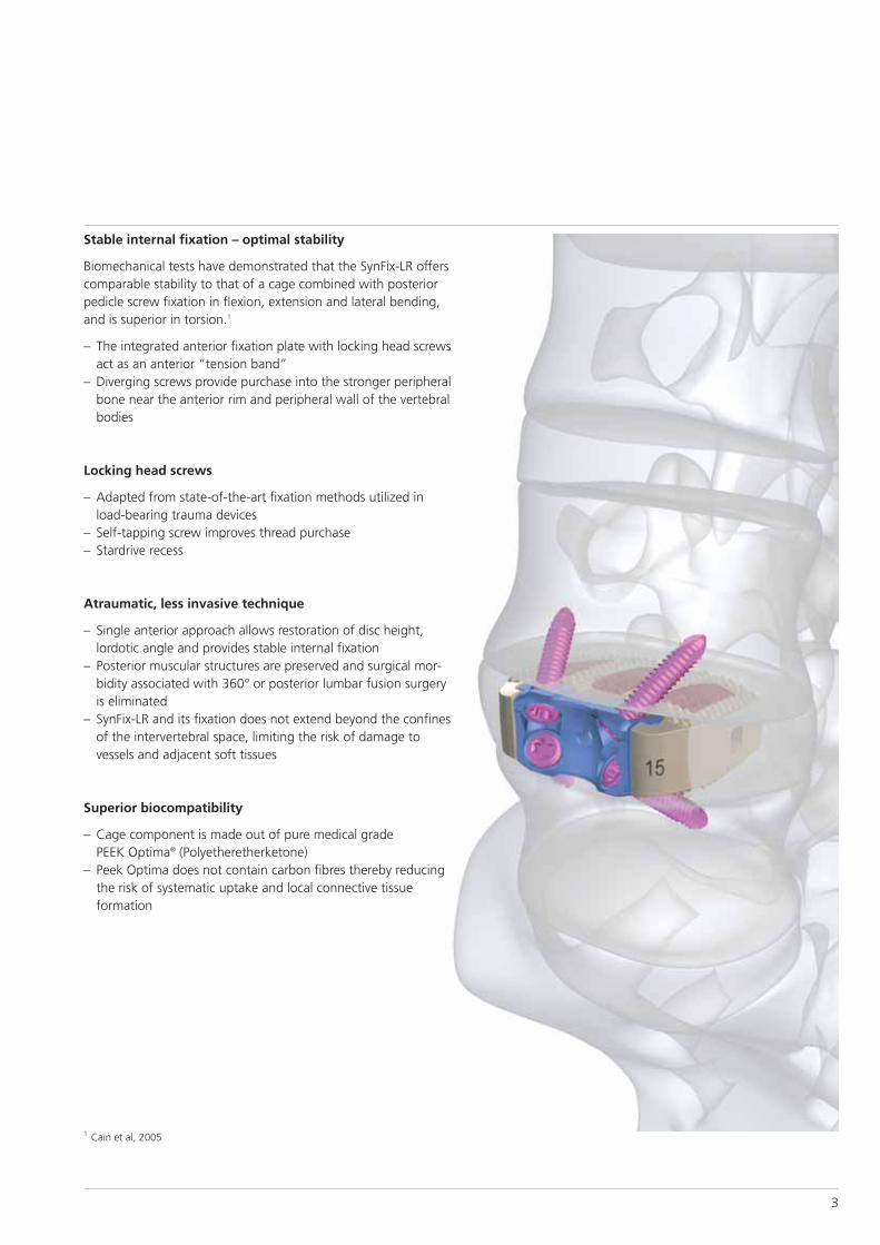
Stable internal fixation – optimal stability
Biomechanical tests have demonstrated that the SynFix-LR offerscomparable stability to that of a cage combined with posteriorpedicle screw fixation in flexion, extension and lateral bending,and is superior in torsion.1
– The integrated anterior fixation plate with locking head screwsact as an anterior “tension band”
– Diverging screws provide purchase into the stronger peripheralbone near the anterior rim and peripheral wall of the vertebralbodies
Locking head screws
– Adapted from state-of-the-art fixation methods utilized inload-bearing trauma devices
– Self-tapping screw improves thread purchase– Stardrive recess
Atraumatic, less invasive technique
– Single anterior approach allows restoration of disc height, lordotic angle and provides stable internal fixation
– Posterior muscular structures are preserved and surgical mor-bidity associated with 360° or posterior lumbar fusion surgeryis eliminated
– SynFix-LR and its fixation does not extend beyond the confinesof the intervertebral space, limiting the risk of damage to vessels and adjacent soft tissues
Superior biocompatibility
– Cage component is made out of pure medical grade PEEK Optima® (Polyetheretherketone)
– Peek Optima does not contain carbon fibres thereby reducingthe risk of systematic uptake and local connective tissueformation
1 Cain et al, 2005
3
4 Synthes SynFix-LR Technique guide
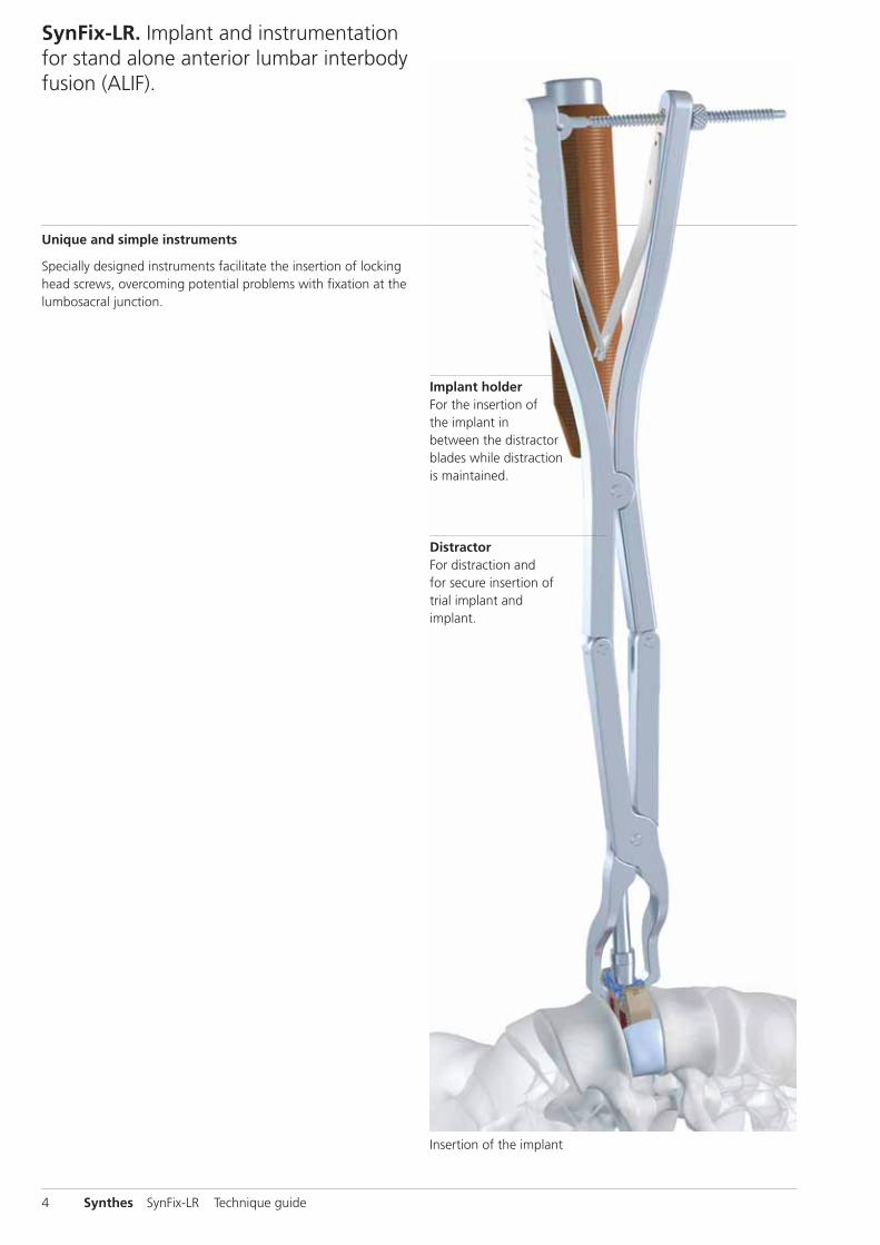
Unique and simple instruments
Specially designed instruments facilitate the insertion of lockinghead screws, overcoming potential problems with fixation at the lumbosacral junction.
SynFix-LR. Implant and instrumentation for stand alone anterior lumbar interbody fusion (ALIF).
DistractorFor distraction andfor secure insertion of trial implant andimplant.
Implant holderFor the insertion of the implant inbetween the distractorblades while distractionis maintained.
Insertion of the implant

5
Aiming device holderFor insertion of the aiming device. Easily removable to facilitateaccess for screw insertion.
Guiding forceps(Tweezers)For guiding awl andscrewdriver into the aiming device.
Awl with cardan jointPenetrates the cortical rim for subsequent screwinsertion.
Aiming deviceFor precise positioning of thelocking head screws.
Self-retaining screwdriverwith cardan jointWith ring marker to indicatethe locking position of thescrew within the titaniumplate.
Opening of the cortical bone for screw insertion Insertion of the locking head screw
AO/ASIF principles
6 Synthes SynFix-LR Technique guide
SynFix-LR is the Synthes implant and instrument system forstand-alone anterior lumbar interbody fusion (ALIF). The implantis designed in accordance with the AO/ASIF Principles for SpinalInterbody Fusion1:
1. Provide adequate stability2. Restore disc height3. Restore lordosis4. Maintain the integrity of the endplates5. Provide an optimised fusion bed6. Atraumatic technique
The integrated anterior fixation plate with locking head screwsprovides an anterior “tension band” and additional stability thatallows its use as a stand-alone implant.
1 Aebi M, Thalgott JS, Webb JK (1998) AO ASIF Principles in Spine Surgery. Berlin: Springer

Indications and contraindications
7
Indications
Lumbar and lumbosacral pathologies which may require anteriorsegmental arthrodesis, including– Localised symptomatic degenerative disc disease – Revision surgery for failed decompression syndrome– Pseudoarthrosis
Contraindications
– Spinal fractures– Spinal tumour– Osteoporosis– Infection
Contraindications for stand-alone application
– Spondylolisthesis– Severe segmental instability

Implants
Footprint 26�32 mm (depth�width)Lordotic Size Posterior Implant Colourangle height code8° 13.5 mm 7 mm 08.802.000S gold
15 mm 8.5 mm 08.802.001S blue17 mm 10.5 mm 08.802.002S purple19 mm 12.5 mm 08.802.003S green
12° 13.5 mm 6 mm 08.802.004S gold15 mm 7 mm 08.802.005S blue17 mm 9 mm 08.802.006S purple19 mm 11 mm 08.802.007S green
Footprint 30�38 mm (depth�width)8° 13.5 mm 6 mm 08.802.008S gold
15 mm 8 mm 08.802.009S blue17 mm 10 mm 08.802.010S purple19 mm 12 mm 08.802.011S green
12° 13.5 mm 5.5 mm 08.802.012S gold15 mm 7 mm 08.802.013S blue17 mm 9 mm 08.802.014S purple19 mm 11 mm 08.802.015S green
Locking head screws
– Self-tapping– Titanium Alloy (TAN)
Diameter Length Screw4.0 mm 15 mm 04.802.2004.0 mm 20 mm 04.802.201
(Recommended)4.0 mm 25 mm 04.802.2024.0 mm 30 mm 04.802.203
8 Synthes SynFix-LR Technique guide
SynFix-LR
– Supplied sterile and pre-assembled (cage with anterior fixationplate)
– Plate components and trial implants are colour coded – Cage component: PEEK Optima– Plate component: Titanium Alloy (TAN)
Width
Depth
Posterior Height
SizeAngle

9
Trial implants
– Colour coded (same colour as the SynFix-LR plate component)
Instruments/Set
Footprint 26�32 mm (depth�width)Lordotic Size Posterior Trial implant Colourangle height code8° 13.5 mm 7 mm 08.802.000 gold
15 mm 8.5 mm 08.802.001 blue17 mm 10.5 mm 08.802.002 purple19 mm 12.5 mm 08.802.003 green
12° 13.5 mm 6 mm 08.802.004 gold15 mm 7 mm 08.802.005 blue17 mm 9 mm 08.802.006 purple19 mm 11 mm 08.802.007 green
Footprint 30�38 mm (depth�width)8° 13.5 mm 6 mm 08.802.008 gold
15 mm 8 mm 08.802.009 blue17 mm 10 mm 08.802.010 purple19 mm 12 mm 08.802.011 green
12° 13.5 mm 5.5 mm 08.802.012 gold15 mm 7 mm 08.802.013 blue17 mm 9 mm 08.802.014 purple19 mm 11 mm 08.802.015 green
Distraction and insertion assembly
– Facilitates simultaneous distraction of the segment and insertion of the trial implants/final implants
– Reduces the force required for implant insertion– Ergonomic– Time-saving
Flexible instruments
New instrumentation improves the accessibility of difficultinsertion points for screws, e.g. screws inserted from a caudal tocranial direction at the lumbosacral level.

01.802.000 Instrument Set for SynFix-LR in Vario Case™68.802.000 Vario Case™ for SynFix-LR, with Lid, without
Contents
10 Synthes SynFix-LR Technique guide
397.113 Distractor, anterior
397.034 Handle for Trial Implants, straight
03.802.031 Holder for Aiming Device for SynFix-LR
03.802.032 Aiming Device for SynFix-LR, 13.5 mm03.802.036 Aiming Device for SynFix-LR, 15 mm03.802.033 Aiming Device for SynFix-LR, 17 mm03.802.034 Aiming Device for SynFix-LR, 19 mm
03.802.035 Awl � 3.2 mm for SynFix-LR
03.802.037 Screwdriver for SynFix-LR
03.802.038 Tweezers for SynFix-LR
03.802.039 Implant Holder for SynFix-LR
03.802.041 Packing Block for SynFix-LR, 26�32 mm03.802.042 Packing Block for SynFix-LR, 30�38 mm
394.585 Cancellous Bone Impactor, 7.0�8.5 mm389.288 Cancellous Bone Impactor, 8.0�2.5 mm
Set

11
1Preoperative planning
The surgical approach depends on the level to be treated, however direct anterior access is required for the insertion of thefixation screws.
Determine the approximate implant size by comparing the SynFix-LR radiograph template (X000045 – X000048) with a lateral radiograph of the patient’s adjacent intervertebral discs.
Notes: – The height indicated on the template is approximately 1 mm
lower than that of the actual cage to account for penetrationof the teeth into the vertebral endplate.
– With the segment fully distracted, the SynFix-LR must fit firmlybetween the endplates before locking head screws are in-serted. When rocking the implant holder backward and for-ward in a cephalad to caudal direction, no toggling of the im-plant should be evident.
– It is recommended to select the maximum implant size inorder to optimize the stability of the segment through tensionin the annulus fibrosus and longitudinal ligaments.
Preoperative planning
2Patient positioning
For an anterior approach to the lower lumbar levels position thepatient in a slight Trendelenburg position.
3Exposure
The locking head screws of the SynFix-LR must be inserted froma direct anterior approach. Expose the intervertebral disc suchthat there is sufficient space on either side of the vertebral mid-line, equal to half the width of the SynFix-LR. This enables theinsertion of the implant without interference from adjacent softtissue structures (major vessels, peritoneum etc.)
Once the cage has been inserted, visualisation of the entireanterior fixation plate is necessary for insertion of the lockinghead screws.

12 Synthes SynFix-LR Technique guide
1Cut anterior window
Cut a rectangular window the width of the SynFix-LR into theanterior longitudinal ligament and annulus fibrosus.
A trial implant (see page 9) may be used as a template to indi-cate the width of the window.
Retain as much of the antero-lateral, lateral and posterior annu-lus as possible, in order to provide the necessary stability of theinstrumented segment.
Note: If a retraction system like the SynFrame is used, payattention to the positioning of soft tissue or Hohmann retractorsas they may interfere with the screw insertion instruments.
Surgical technique
2Prepare disc space
Excise the disc material and remove the cartilaginous endplatesto expose the underlying bony vertebral endplates.
Adequate clearance of the endplates is important to enable theprovision of a vascular supply to the bone graft. Excessive clear-ance or use of a rasp may, however, weaken the endplate andresult in subsidence of the cage.
Once the endplates have been prepared, complete eventualadditional surgical procedures (i.e. removal of a disc fragmentfrom the spinal canal).
Note: It is essential that all nuclear material and the innerannulus are removed to prevent displacement of disc materialinto the spinal canal during cage insertion and interferencewith bone in-growth.

13
3Distract segment
Required instruments
Anterior Distractor 397.113
Distraction of the segment is essential for restoration of discheight, opening of the neural foramina and initial stability of theSynFix-LR.
Distract the segment with the anterior distractor. To ensure thatthe SynFix-LR is inserted symmetrically into the disc space, thecentral line on the distractor blades should be aligned with theanterior midline of the vertebral bodies.
Compress the distractor handle to open the disc space.
Note: The distractor must be firmly held in place during dis-traction and insertion of the trial implant or implant to preventits ejection from the disc space and possible injury to adjacentstructures.
14 Synthes SynFix-LR Technique guide
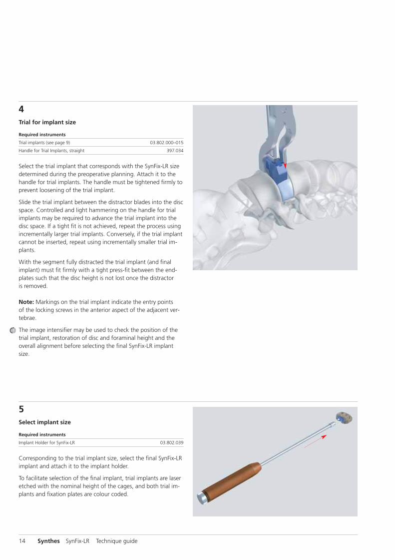
4Trial for implant size
Required instruments
Trial implants (see page 9) 03.802.000–015
Handle for Trial Implants, straight 397.034
Select the trial implant that corresponds with the SynFix-LR sizedetermined during the preoperative planning. Attach it to thehandle for trial implants. The handle must be tightened firmly toprevent loosening of the trial implant.
Slide the trial implant between the distractor blades into the discspace. Controlled and light hammering on the handle for trialimplants may be required to advance the trial implant into thedisc space. If a tight fit is not achieved, repeat the process usingincrementally larger trial implants. Conversely, if the trial implantcannot be inserted, repeat using incrementally smaller trial im-plants.
With the segment fully distracted the trial implant (and finalimplant) must fit firmly with a tight press-fit between the end-plates such that the disc height is not lost once the distractoris removed.
Note: Markings on the trial implant indicate the entry pointsof the locking screws in the anterior aspect of the adjacent ver-tebrae.
The image intensifier may be used to check the position of thetrial implant, restoration of disc and foraminal height and theoverall alignment before selecting the final SynFix-LR implantsize.
5Select implant size
Required instruments
Implant Holder for SynFix-LR 03.802.039
Corresponding to the trial implant size, select the final SynFix-LRimplant and attach it to the implant holder.
To facilitate selection of the final implant, trial implants are laseretched with the nominal height of the cages, and both trial im-plants and fixation plates are colour coded.

15
6Pack implant with bone graft
Required instruments
Packing Block for SynFix-LR, 26�32 mm 03.802.041
Packing Block for SynFix-LR, 30�38 mm 03.802.042
Cancellous Bone Impactor, 7.0�8.5 mm 394.585
Cancellous Bone Impactor, 8.0�2.5 mm 389.288
After attaching the SynFix-LR to the implant holder insert it intothe appropriate packing block.
Note: The implant holder has to be attached firmly to the fixa-tion plate in order to avoid damage either of the implant holderor the plate.
Use a cancellous bone impactor to firmly pack the graft materialinto the implant cavities.
It is important to fill the cage until the graft protrudes from theperforations in the cage, to ensure optimal contact with the vertebral endplates.
7Insert implant
Required instruments
Anterior Distractor 397.113
With the SynFix-LR ready for insertion, distract the segmentagain. Fix the distraction by tightening the locking nut on thedistractor handle.
Slide the SynFix-LR between the disctractor blades into the discspace.
Fully introduce the SynFix-LR into the disc space with lighthammering.
Note: The distractor should be held firmly in place duringimplant insertion.
Verify final implant position with the help of an intra-operativelateral X-ray. It is recommended to place the cage such that thescrews subsequently will penetrate the endplates of the superiorand inferior vertebral bodies close to the anterior rim.

16 Synthes SynFix-LR Technique guide
8Remove instruments
When the SynFix-LR is correctly positioned loosen the lockingnut on the distractor handle and release the distraction.
Gently remove the distractor while the implant holder is holdingthe SynFix-LR in position.
After the distractor has been removed ensure a secure fit bylightly hammering on the implant holder.
Release the implant holder. The implant should now have itsoptimal position.
Note: All instruments must be removed carefully to avoid possi-ble injury to adjacent structures.
c
a
b
17
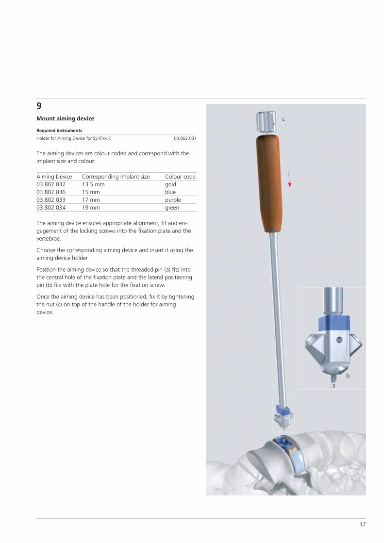
9Mount aiming device
Required instruments
Holder for Aiming Device for SynFix-LR 03.802.031
The aiming devices are colour coded and correspond with theimplant size and colour:
Aiming Device Corresponding implant size Colour code03.802.032 13.5 mm gold03.802.036 15 mm blue03.802.033 17 mm purple03.802.034 19 mm green
The aiming device ensures appropriate alignment, fit and en-gagement of the locking screws into the fixation plate and thevertebrae.
Choose the corresponding aiming device and insert it using theaiming device holder.
Position the aiming device so that the threaded pin (a) fits intothe central hole of the fixation plate and the lateral positioningpin (b) fits with the plate hole for the fixation screw.
Once the aiming device has been positioned, fix it by tighteningthe nut (c) on top of the handle of the holder for aiming device.

18 Synthes SynFix-LR Technique guide
10Insert awl
Required instruments
Awl � 3.2mm for SynFix-LR 03.802.035
Tweezers for SynFix-LR 03.802.038
For better visualisation of the operative site it is recommendedto remove the aiming device holder temporarily, leaving the aim-ing device attached to the fixation plate.
Insert the awl with the Tweezers for SynFix-LR, which ensuresdirectional control. Prepare the cortical rim of the vertebral bodyfor screw insertion by applying pressure on the handle of theawl in conjunction with rotational motions.
Notes:– Use the tweezers to control the tip of the awl and to avoid
injury to the surrounding abdominal viscera or vessels.– The tweezers can also be used for removal of the awl in order
to avoid damage of adjacent structures.
11Insert first screw
Required instruments
Screwdriver for SynFix-LR 03.802.037
Tweezers for SynFix-LR 03.802.038
According to the preoperative planning and intraoperative find-ings select the appropriate screw length (20 mm screws are rec-ommended for use in most cases).
Insert the self-tapping screws with the self-retaining screwdriverand the tweezers.
Notes:– The tweezers allow control of the screw during insertion. This
avoids damage of the surrounding abdominal viscera orvessels. They are of particular value in lumbosacral instrumen-tations for screw insertion into the inferior endplate of the level L5.
– The tweezers can also be used for removal of the screwdriverin order to avoid damage of adjacent structures.
19
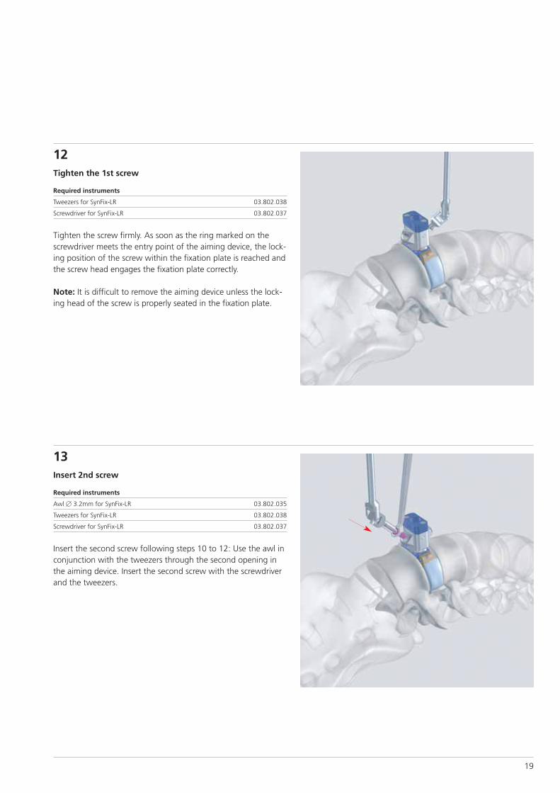
12Tighten the 1st screw
Required instruments
Tweezers for SynFix-LR 03.802.038
Screwdriver for SynFix-LR 03.802.037
Tighten the screw firmly. As soon as the ring marked on thescrewdriver meets the entry point of the aiming device, the lock-ing position of the screw within the fixation plate is reached andthe screw head engages the fixation plate correctly.
Note: It is difficult to remove the aiming device unless the lock-ing head of the screw is properly seated in the fixation plate.
13Insert 2nd screw
Required instruments
Awl � 3.2mm for SynFix-LR 03.802.035
Tweezers for SynFix-LR 03.802.038
Screwdriver for SynFix-LR 03.802.037
Insert the second screw following steps 10 to 12: Use the awl inconjunction with the tweezers through the second opening inthe aiming device. Insert the second screw with the screwdriverand the tweezers.
1
2
20 Synthes SynFix-LR Technique guide
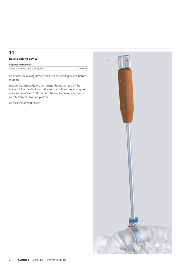
14Rotate aiming device
Required instruments
Holder for Aiming Device for SynFix-LR 03.802.031
Re-attach the aiming device holder to the aiming device beforerotation.
Loosen the aiming device by turning the nut on top of theholder of the handle four to five turns (1). Now the aiming de-vice can be rotated 180° without having to disengage it com-pletely from the fixation plate (2).
Re-lock the aiming device.

21
15Insert 3rd and 4th screw
For insertion of the third and fourth screw, repeat steps 10 to13.
16Remove instruments
Once the fixation plate is secured, remove the aiming device byturning the nut on top of the aiming device holder.
22 Synthes SynFix-LR Technique guide
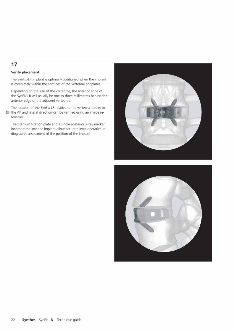
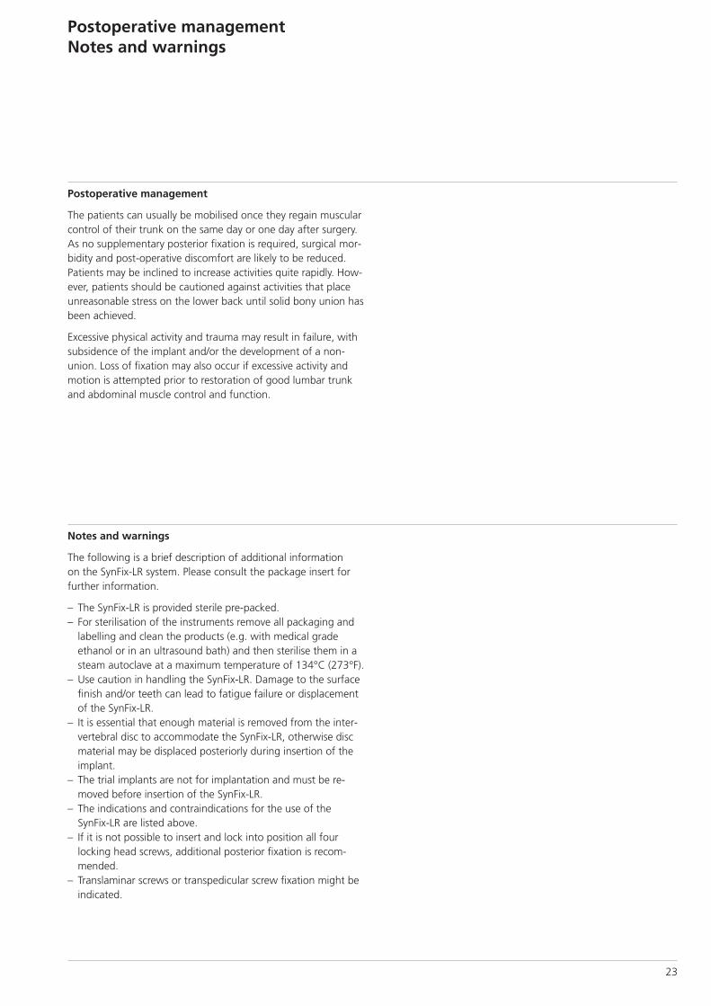
17Verify placement
The SynFix-LR implant is optimally positioned when the implantis completely within the confines of the vertebral endplates.
Depending on the size of the vertebrae, the anterior edge ofthe SynFix-LR will usually be one to three millimetres behind theanterior edge of the adjacent vertebrae.
The location of the SynFix-LR relative to the vertebral bodies inthe AP and lateral direction can be verified using an image in-tensifier.
The titanium fixation plate and a single posterior X-ray markerincorporated into the implant allow accurate intra-operative ra-diographic assessment of the position of the implant.
23
Postoperative managementNotes and warnings
Postoperative management
The patients can usually be mobilised once they regain muscularcontrol of their trunk on the same day or one day after surgery.As no supplementary posterior fixation is required, surgical mor-bidity and post-operative discomfort are likely to be reduced. Patients may be inclined to increase activities quite rapidly. How-ever, patients should be cautioned against activities that placeunreasonable stress on the lower back until solid bony union hasbeen achieved.
Excessive physical activity and trauma may result in failure, withsubsidence of the implant and/or the development of a non-union. Loss of fixation may also occur if excessive activity andmotion is attempted prior to restoration of good lumbar trunkand abdominal muscle control and function.
Notes and warnings
The following is a brief description of additional informationon the SynFix-LR system. Please consult the package insert forfurther information.
– The SynFix-LR is provided sterile pre-packed.– For sterilisation of the instruments remove all packaging and
labelling and clean the products (e.g. with medical gradeethanol or in an ultrasound bath) and then sterilise them in asteam autoclave at a maximum temperature of 134°C (273°F).
– Use caution in handling the SynFix-LR. Damage to the surfacefinish and/or teeth can lead to fatigue failure or displacementof the SynFix-LR.
– It is essential that enough material is removed from the inter-vertebral disc to accommodate the SynFix-LR, otherwise discmaterial may be displaced posteriorly during insertion of theimplant.
– The trial implants are not for implantation and must be re-moved before insertion of the SynFix-LR.
– The indications and contraindications for the use of the SynFix-LR are listed above.
– If it is not possible to insert and lock into position all fourlocking head screws, additional posterior fixation is recom-mended.
– Translaminar screws or transpedicular screw fixation might beindicated.

24 Synthes SynFix-LR Technique guide
Bibliography
Pavlov PW, Meijers H, van Limbeek J, Jacobs WC, Lemmens JA,Obradov-Rajic M, de Kleuver M (2004) Good outcome andrestoration of lordosis after anterior lumbar interbody fusion andadditional posterior fixation. Spine 29(17): 1893-9
Steffen T, Tsantrizos A, Aebi M (2000) Effect of implant designand endplate preparation on the compressive strength of inter-body fusion constructs. Spine 25(9): 1077-84
Aebi M, Thalgott JS, Webb JK (1998) AO/ASIF Principles in SpineSurgery. Berlin: Springer
Watkins RG. Anterior Lumbar Interbody Fusion: Surgical Tech-nique in Lumbar Interbody Fusion, eds. P.M. Lin, K. Gill. AspenPublishers, Inc., Rockwille
Rüedi TP, Murphy WM (2000) AO Principles of Fracture Manage-ment. Stuttgart New York: Thieme
Frigg R, Appenzeller A, Christensen R, Frenk A, Gilbert S, Scha-van R. (2001) The development of the distal femur Less InvasiveStabilization System (LISS). Injury 32(3):SC24-31
Baumgart FW, Cordey J, Morikawa K, Perren SM, Rahn BA,Schavan R, Snyder S (1993) AO/ASIF self-tapping screws (STS).Injury 24(1):1-17
Cain MJ, Schleicher P, Gerlach R, Pflugmacher R, Scholz M,Kandziora F (2005) A new stand alone ALIF device:Biomechanical comparison with established fixation methods.Spine 30(23):2631-6

01230123 036.
000.
915
SE_0
1924
0 A
A50
0500
15©
Syn
thes
2006
Prin
ted
in S
witz
erla
ndLA
GSu
bjec
t to
mod
ifica
tions
.
Presented by


