III
SYNTHESIS AND CHARACTERIZATION OF EFB
CLINKER SUPPORTED NICKEL AND COBALT
CATALYSTS FOR METHANE DRY REFORMING
CHAN HAN JIE
Thesis submitted in partial fulfilment of the requirements
for the award of the degree of
Bachelor of Chemical Engineering
Faculty of Chemical & Natural Resources Engineering
UNIVERSITI MALAYSIA PAHANG
JANUARY 2015
©CHAN HAN JIE (2015)
VIII
ABSTRACT
Methane dry reforming is environmental friendly due to the potential sequestration of
CO2. Therefore, substantial research works have been carried out to develop reforming
catalysts that exhibit high catalytic performance and excellent longevity. The current
work reports on the synthesis of 20wt%Co/80wt%EFB clinker and 20wt%Ni/80wt%EFB
clinker catalysts via wet-impregnation technique, followed by various characterization
techniques such as BET, XRD, XRF, TGA and FESEM. The BET specific surface area
of Co/EFB clinker and Ni/EFB clinker catalyst were 2.83 m2g-1 and 2.37 m2g-1,
respectively. In addition, XRD diffractogram of EFB clinker showed two highest peaks
at around 2θ = 27.2° and 31.5°, which can be attributed to CaO and K2O species,
respectively. This finding was also consistent with XRF analysis where potassium (K)
and calcium (Ca) were positively identified. Subsequently, methane dry reforming studies
revealed that Ni/EFB clinker catalyst always yielded higher formation rates of H2 and
CO. Indeed, the rate was maximum at CO2:CH4 feed ratio of unity. The average
conversion of CH4 for reactions using Co/EFB clinker and Ni/EFB clinker catalyst are
obtained to be 78.26 % and 78.19 % respectively. Meanwhile, the average conversion of
CO2 for reactions using Co/EFB clinker and Ni/EFB clinker catalyst are 80.40 % and
81.17 % respectively. When reaction temperatures were varied, the activation energy over
Co/EFB clinker was 124.4 kJ mol-1 while that for the reaction over the Ni/EFB clinker
catalyst was 113.0 kJ mol-1. Post reforming reaction, oxidation profiles of the used
catalysts indicated carbon-free condition. This was corroborated by the FESEM images
for both sets of used catalysts, where no carbon whisker was found.
IX
ABSTRAK
Tindak balas metana dan karbon dioksida merupakan satu proses yang mesra alam. Oleh
itu, banyak penyelidikan telah dijalankan bagi menghasilkan pemangkin yang berprestasi
tinggi dan berhayat panjang. Kerja ini bertujuan untuk menghasilkan pemangkin yang
berasaskan Ni dan Co yang disokong oleh klinker tandan buah sawit melalui kaedah
impregnasi basah dengan formulasi yang 20-80. Pelbagai teknik pencirian seperti BET,
XRD, XRF, TGA, FESEM dan EDX telah digunakan untuk mendapatkan ciri-ciri
pemangkin yang dihasil. Kajian BET mendapati bahawa kawasan permukaan tertentu
BET untuk pemangkin Co/EFB klinker dan Ni/EFB klinker adalah 2.83 m2g-1 and 2.37
m2g-1 masing-masing. Di samping itu, diffractogram XRD EFB klinker menunjukkan dua
puncak di 2θ = 27.2 ° dan 31.5 °, yang boleh dikaitkan dengan spesis Cao dan K2O. Carian
ini juga konsisten dengan analisis XRF iaitu kalium (K) dan kalsium (Ca) dapat dikenal
pasti secara positif. Selain itu, kajian tindak balas metana dan karbon dioksida
mendedahkan bahawa pemangkin Ni/EFB klinker sentiasa menghasilkan kadar
penghasilan H2 dan CO yang lebih tinggi. Sesungguhnya, kadar itu adalah maksimum
pada CO2:CH4 bernisbah 1:1. Penukaran purata CH4 untuk tindak balas menggunakan
pemangkin Co/EFB klinker dan Ni/EFB klinker didapati ialah 78.26% dan 78.19%
masing-masing. Sementara itu, penukaran purata CO2 untuk tindak balas menggunakan
pemangkin Co/EFB klinker dan Ni/EFB klinker didapati ialah 80.40% dan 81.17%
masing-masing. Apabila suhu tindak balas telah diubah, tenaga pengaktifan bagi Co/EFB
klinker adalah 124.4 kJmol-1 manakala bagi tindak balas yang pakai pemangkin Ni/EFB
klinker adalah 113.0 kJmol-1. Kedua-dua pemangkin yang telah dipakai digunakan untuk
manjalankan analisis profil pengoksidaan. Analisis bagi kedua-dua pemangkin mendapati
bahawa kedua-dua set pemangkin yang diguna tidak menhadapi masalah pemendapan
karbon yang kritikal.
X
TABLE OF CONTENTS
SUPERVISOR’S DECLARATION ............................................................................... IV
STUDENT’S DECLARATION ...................................................................................... V
Dedication ....................................................................................................................... VI
ACKNOWLEDGEMENT ............................................................................................. VII
ABSTRACT ................................................................................................................. VIII
ABSTRAK ...................................................................................................................... IX
TABLE OF CONTENTS ................................................................................................. X
LIST OF FIGURES ....................................................................................................... XII
LIST OF TABLES ....................................................................................................... XIV
LIST OF ABBREVIATIONS ....................................................................................... XV
LIST OF ABBREVIATIONS ...................................................................................... XVI
1 INTRODUCTION .................................................................................................... 1
1.1 Background ........................................................................................................ 1
1.2 Problem Statement and Motivation .................................................................... 2
1.3 Objective ............................................................................................................ 3
1.4 Scopes ................................................................................................................ 3
1.5 Outline of Thesis ................................................................................................ 4
2 LITERATURE REVIEW ......................................................................................... 5
2.1 General Overview .............................................................................................. 5
2.2 Steam Reforming Reaction Process ................................................................... 5
2.3 Dry Reforming Reaction Process ....................................................................... 5
2.4 Reactions in methane dry reforming .................................................................. 6
2.5 Reforming Catalyst ............................................................................................ 8
2.6 Catalyst Preparation ......................................................................................... 14
2.7 Catalyst Deactivation ....................................................................................... 15
2.8 Summary .......................................................................................................... 17
3 MATERIALS AND METHODS ............................................................................ 18
3.1 Materials ........................................................................................................... 18
3.2 Catalyst Physicochemical Characterization ..................................................... 18
3.2.1 Brunauer-Emmett-Teller (BET) ................................................................ 19
3.2.2 X-ray Diffraction (XRD) ........................................................................... 21
3.2.3 Field Emission Scanning Electron Microscopy (FESEM) ....................... 23
3.2.4 Energy-dispersive X-ray Spectroscopy (EDX) ......................................... 24
3.2.5 Thermo gravimetric analysis (TGA) ......................................................... 25
3.2.6 X-ray Fluorescence (XRF) ........................................................................ 27
3.3 Catalyst reaction ............................................................................................... 28
4 RESULTS AND DISCUSSIONS ........................................................................... 30
4.1 Catalyst Preparation ......................................................................................... 30
4.2 Fresh Catalyst Characterization ....................................................................... 31
4.2.1 X-ray Fluorescence (XRF) ........................................................................ 31
4.2.2 XRD ........................................................................................................... 32
4.2.3 Liquid N2 Physisorption (BET) ................................................................. 33
4.2.4 Thermogravimetric Analysis (TGA).......................................................... 36
4.2.5 FESEM Imaging ....................................................................................... 38
4.2.6 Energy-dispersive X-ray Spectroscopy (EDX) ......................................... 38
XI
4.3 Dry Reforming Reaction Studies ..................................................................... 39
4.3.1 Mass Transfer Limitation Studies ............................................................. 39
4.3.2 Catalyst Performance ............................................................................... 40
4.3.3 Effect of Feed Ratio and Reaction Temperature ...................................... 43
4.3.4 Longevity Study ......................................................................................... 49
4.4 Used Catalyst Characterization ........................................................................ 51
4.4.1 Thermogravimetric analysis (TGA) .......................................................... 51
4.4.2 FESEM Imaging ....................................................................................... 52
4.4.3 Energy Dispersive X-ray spectrometry (EDX) ......................................... 53
5 CONCLUSIONS AND RECOMMENDATIONS ................................................. 54
5.1 Conclusions ...................................................................................................... 54
5.2 Recommendations ............................................................................................ 54
REFRENCES .................................................................................................................. 56
APPENDIX A ................................................................................................................. 60
APPENDIX B ................................................................................................................. 61
APPENDIX C ................................................................................................................. 79
XII
LIST OF FIGURES
Figure 2.1: Equilibrium constants of reactions involving in CH4-CO2 reaction at
different temperatures and atmospheric pressure (Source: Nikoo and Amin, 2011) ........ 7
Figure 2.2: Carbon deposition as a function of temperature and CO2/CH4 ratio .......... 16
Figure 3.1: Deriving Bragg's Law using the reflection geometry and applying
trigonometry .................................................................................................................... 21
Figure 3.2: Schematic diagram of a general Field Emission SEM ................................ 23
Figure 3.3: Schematic diagram of EDX ........................................................................ 24
Figure 3.4: Schematic diagram of TGA ........................................................................ 26
Figure 3.5: Schematic diagram of XRF ......................................................................... 28
Figure 3.6: Experimental Setup ..................................................................................... 29
Figure 4.1: XRD spectra of Co/EFB clinker catalyst, Ni/EFB clinker catalyst and EFB
clinker ............................................................................................................................. 32
Figure 4.2: Isotherm plot of (a) EFB clinker, (b) Co/EFB clinker and (c) Ni/EFB
clinker ............................................................................................................................. 35
Figure 4.5: Weight (%) versus Temperature (K) over both catalysts at 20 K min-1 ...... 36
Figure 4.6: Weight profile (%) versus Temperature (K) over (a) Co/EFB clinker and (b)
Co/EFB clinker catalyst at different ramping rate (10, 15 and 20 K min-1) ................... 37
Figure 4.8: SEM image of (a) fresh EFB clinker support, (b) fresh Co/EFB clinker
catalyst and (c) fresh Ni/EFB clinker catalyst ................................................................ 39
Figure 4.9: EDX of (a) 20wt% Co/EFB clinker catalyst (b) 20wt% Ni/EFB clinker ... 38
Figure 4.10: Transient profile of conversion of CH4 ..................................................... 41
Figure 4.11: Average conversion of CH4 and CO2 for the catalyst tested in the dry
reforming of methane. (T = 1173K; P = 1atm; CO2: CH4 = 1) ...................................... 42
Figure 4.12: Rate of formation for both H2 and CO. ..................................................... 43
Figure 4.13: Average conversion of CH4 for the catalyst tested in the dry reforming of
methane for various feed ratio. (T = 1173K; P = 1atm) ................................................. 44
Figure 4.14: (a) Rate of consumption of CH4 (b) Rate of formation of H2 versus various
feed ratio. (T = 1173K; P = 1atm) .................................................................................. 45
Figure 4.15: Rate of consumption of CH4 versus temperature (P = 1atm; CO2: CH4 = 1)
........................................................................................................................................ 46
Figure 4.16: Rate of formation of H2 versus temperature (P = 1atm; CO2: CH4 = 1) ... 47
Figure 4.17: Rate of formation of CO versus temperature (P = 1atm; CO2: CH4 = 1) .. 47
Figure 4.18: Rate of formation of H2 and CO and rate of consumption of CH4 with
various temperatures for Co/EFB clinker catalyst .......................................................... 48
Figure 4.19: Rate of formation of H2 and CO and rate of consumption of CH4 with
various temperatures for Ni/EFB clinker catalyst ........................................................... 49
Figure 4.20: Transient Profiles of CH4 Conversion ....................................................... 50
XIII
Figure 4.21: Weight change (%) versus temperature (K) .............................................. 51
Figure 4.22: FESEM image of spent Co/EFB clinker catalyst ...................................... 52
Figure 4.23: FESEM image of spent Ni/EFB clinker catalyst ....................................... 52
Figure 4.24: EDX of spent Co/EFB clinker catalyst ..................................................... 53
Figure 4.25: EDX of spent Ni/EFB clinker catalyst ...................................................... 53
XIV
LIST OF TABLES
Table 2.1: Reaction in CO2 reforming of methane (Source: Nikoo and Amin, 2011) .... 6
Table 2.2: Summary of previous research and its significant result ................................ 9
Table 3.1: List of chemical and its purity ...................................................................... 18
Table 3.2: List of gases and its purity ............................................................................ 18
Table 4.3: XRF Results .................................................................................................. 31
Table 4.1: Crystallite size determined for the peak around 2θ = 37.01° for Co/EFB
clinker catalyst and 2θ = 43.38° for Ni/EFB clinker catalyst. ........................................ 33
Table 4.2: BET specific surface area and pore volume of sample ................................. 35
Table 4.4: Average Conversion of CH4 and CO2 .......................................................... 41
Table 4.5: Activation Energy table ................................................................................ 48
XV
LIST OF ABBREVIATIONS
a : effective cross-sectional area of one adsorbate molecule
C : dimensionless constant that related to the enthalpy adsorption of adsorbate gas
d : spacing between layers of atoms
D : crystalline size
Ea : activation energy
K : dimensionless shape factor
kSch : Scherrer constant
n : order of reflection (integer)
P : partial vapour pressure of adsorbate gas in equilibrium
P0 : saturated pressure of adsorbate gas
P/Po : relative pressure
R : gas constant
T : temperature
Va : volume of gas adsorbed at STP
VM : volume of gas adsorbed corresponding to monolayer coverage
Greek
(ΔGr) : Gibbs free energy change of reaction
λ : wavelength
β : line broadening at half the maximum intensity
θ : Bragg angle
XVI
LIST OF ABBREVIATIONS
BET Brunauer-Emmett-Teller
BOD Biochemical Oxygen Demand
COD Chemical Oxygen Demand
GDP Gross Domestic Product
EDX Energy Dispersive X-ray Spectroscopy
EFB Empty Fruit Bunch
FESEM Field Emission Scanning Electron Microscopy
OPF Oil Palm Fronds
OPT Oil Palm Trunks
POME Palm Oil Mill Effluent
SEM Scanning Electron Microscope
STP Standard temperature and pressure
TGA Thermogravimetric Analysis
XRD X-ray Diffraction
1
1 INTRODUCTION
1.1 Background
Synthesis gas is a fuel gas mixture comprised of CO and H2. It is a vital feedstock for
downstream petrochemical industries i.e. gasoline, ammonia, methanol etc. As the world
grapples with potentially-devastating energy crunch situation, renewable energy such as
synthesis gas has been touted as a potential saviour.
Significantly, in Malaysia palm oil mill effluent or also known as POME is a highly
polluting wastewater with high chemical oxygen demand (COD) and biochemical oxygen
demand (BOD) (Lam & Lee, 2011). Under ambient conditions, degradation of POME
usually releases a large amount of CH4 and CO2 (collectively known as biogas) into the
atmosphere, which may worsen the global warming (Schuchardt et al., 2008). Carbon
dioxide (CO2) has been identified as one of the most significant greenhouse gases arising
from anthropogenic activities. Hence, mankind needs to curb CO2 emissions in order to
counteract global warming (Er-rbib et al., 2012). One of the propositions is to utilize CH4
and CO2 simultaneously via dry (CO2) reforming pathway. The dry reforming of methane
results in product with a lower H2:CO ratio (< 2.0) which is more favourable for olefins
or methanol synthesis compared to the yield from the conventional steam reforming
which normally produces H2:CO ratios > 3.0 (Siahvashi & Adesina, 2013). Besides, the
use of CO2 as co-reactant has also attracted growing attention due to the potential
sequestration of CO2 and energy savings (Siahvashi & Adesina, 2013).
Indeed, catalysts play a vital role in the aforementioned reaction. Catalyst is usually
comprised of active metal and support. A supporter is usually a solid with a high surface
area, to which a catalyst is affixed. Relentless efforts have been dedicated to maximize
the surface area of a catalyst by distributing it over the support (McNaught & Wilkinson,
2014). Previous studies and reviews have been published on the Ni based metal with
different supported catalysts employed in the light hydrocarbon dry reforming. An
evaluative investigation of propane CO2 reforming over bimetallic alumina supported
5%Mo-10%Ni catalyst has been carried out in a fixed bed reactor at 0.1 M Pa and
temperatures ranging from 823 – 973K. It was found that Mo-Ni is a stable and active
2
catalyst at different temperature during the dry reforming process (Siahvashi et al., 2013).
Besides, numerous supported catalysts have been tested, especially Ni- and noble metal-
based catalysts, and they have been found to exhibit promising catalytic performance.
Conversion of CH4 and CO2 to synthesis gas, approaching those defined by
thermodynamic equilibrium, can be obtained over the aforementioned catalysts as long
as sufficient contact times are maintained.
One of the major problems encountered during dry reforming is the deactivation of the
catalysts dues to carbon deposition. To alleviate the deactivation problem arising from Ni
catalysts coking, it has been shown that addition of alkali or alkaline earth oxide to the Ni
based catalyst lead to drastic decrease in the number of sites for carbon formation, while
sufficiently maintaining the active sites for the reforming (Lemonidou et al., 1998). From
the EDX result of EFB clinker, it was found that EFB has a basic characteristic and it
should be suitable to act as the supporter for the Ni-based and Co-based catalysts.
1.2 Problem Statement and Motivation
Oil palm is the most important commodity from Malaysia with significant contribution
to its gross domestic product (GDP). Lignocelluosic biomass which is produced from the
oil palm industries include parts such as oil palm trunks (OPT), oil palm fronds (OPF),
empty fruit bunches (EFB) and palm oil mill effluent (POME). Nevertheless, the presence
of these oil palm wastes has created a major disposal problem (Abdullah & Sulaiman,
2013). EFB are the main source of biomass that could be utilized by the power plant due
to its ready-availability as daily biomass-waste. Most of the plantations use a small
fraction of this EFB waste for internal use, with a large portion being put aside for either
biodegrading into compost, or at times burnt to avoid space loss by storage (Matt et al.,
2014). As a fuel, EFB is burnt in a furnace to generate heat and electricity for sustaining
palm oil mill operation. The residue from this process is what is known as EFB clinker
whereby it will be adopted for the first time in this work as supporter for Ni catalyst for
methane dry reforming reaction. Most of the previous studies primarily investigated the
development of catalyst for high catalytic performance and stability. Therefore, an
optimum conversion of synthesis gas can be achieved. However, most of these works did
not focus on the environment impact of the catalyst. To illustrate, an evaluative
investigation of propane CO2 reforming over bimetallic alumina supported 5%Mo-
3
10%Ni catalyst sounds promising in dry reforming (Siahvashi et al., 2013). In fact,
calcium aluminate has been proven to be active with lower coke deposition for the
reaction of reforming (Lemonidou et al., 1998). From the characterisation of EFB clinker,
high percentage of K and Ca were found. Hence it is believed to be basic. A basic catalyst
can reduce back pressure in the packed bed column as carbon deposition will be reduced
substantially (Ranjbar & Rezaei, 2012b). Last but not least, it is worth to explore the
possibility of this palm oil industries waste as catalyst supporter in this study.
1.3 Objective
This research work is carried out to synthesize and characterize EFB clinker supported
20wt% Co and 20wt%Ni catalysts for methane dry reforming studies at atmospheric
pressure.
1.4 Scopes
In order to achieve the outlined objective of this work, the following scopes have been
identified:
i) Catalysts Preparation:
The 20wt%Co/80wt%EFB and 20wt%Ni/80wt%EFB catalysts were prepared
via wet-impregnation method.
ii) Catalyst Characterisation:
The methods applied in this study were BET, XRD, XRF, TGA, FESEM and
EDX. BET was used to find out the specific surface are, pore volume and pore
size distribution sample of catalysts. The crystalline structure and the size of
crystallite diameter were determined via XRD. Besides, XRF was employed
for analysis of major and trace elements in the EFB clinker. The catalyst-gas
interaction profile was obtained from TGA instrument. In addition, TGA also
allowed the determination of coke location as well. Lastly, the image of coke
deposit structure at the sample catalysts can be observed via FESEM while
EDX shows the composition of element that contained in the sample catalysts.
4
iii) Catalyst Reaction:
The catalytic screening was carried out by placing 0.3 g of catalyst into the
stainless steel fixed-bed reactor (ID: 10 mm) supported by two layers of quartz
wool. The feed comprised of the CH4 and CO2 mixture at equal proportion
and the reaction temperature was set at 1173 K for catalyst screening studies.
Subsequently, the CO2 to CH4 ratios and temperatures were varied between
1073 – 1173 K to determine the ratio of product produced by the best catalyst.
1.5 Outline of Thesis
This thesis is divided into four chapters. Chapter 1 describes the problem statements that
motivate the current work. In the same chapter, the objective and scopes of the study are
presented. Chapter 2 reviews the background of the study and describes previous works
of other researchers. The materials and methodology used in the study and design of the
experiments are discussed in Chapter 3. In Chapter 4, experimental results include
characterization analysis and some kinetics modelling will be presented. Finally, the
conclusions and some recommendations of this thesis and outlook for future work are
summarized in Chapter 5.
5
2 LITERATURE REVIEW
2.1 General Overview
Dry (CO2) reforming of methane is a well-studied reaction that is of both scientific and
industrial importance. This reaction produces syngas that can be used to produce wide
range of products especially in downstream petrochemical processes. Conventional
production of syngas is via natural gas steam reforming. However, fossil hydrocarbons
resources are decreasing in the face of growing demand from developing countries; hence
a sudden spike in energy price. In lieu of this, synthesis gas availability as an alternative
fuel source (via Fischer-Tropsch synthesis) in addition to the aforementioned processes
is clearly desirable. In this section, previous studies related to the reforming reaction,
related catalysts, as well as coke deactivation phenomenon are presented.
2.2 Steam Reforming Reaction Process
The most established process for syngas production is natural gas/ methane steam
reforming. This reaction is endothermic and takes place at temperature above 1123 K.
The reforming reaction can be represented as:
CH4 + H2O ↔ CO + 3H2 ∆H0298K = +206 kJ/mol Eq. (2-1)
CO + H2O ↔ CO2 + H2 ∆H0298K = -41 kJ/mol Eq. (2-2)
For the steam reforming reaction, the production of hydrogen increased with pressure
because the forward water-gas shift reaction produced additional hydrogen by the
reaction of CO with water (Oyama et al., 2012).
2.3 Dry Reforming Reaction Process
The methane dry reforming is a highly endothermic reaction and the reaction occurs at
1073-1073 K at atmospheric pressure. Theoretically, the process has a unity molar ratio
for H2/CO. The reforming reaction can be represented as:
CH4 + CO2 → 2CO + 2H2 ∆H298K=247 kJ/mole Eq. (2-3)
For the production of synthesis gas and hydrogen, the dry reforming have an
environmental benefit as it consumes CO2. However, there are some drawbacks of dry
6
reforming methane, viz. catalyst sintering at high temperature, a possibly lower H2/CO
ratio compared to steam reforming attributed to the reverse water-gas shift reaction
(Oyama et al., 2012) and catalyst deactivation due to carbon deposition from either
methane cracking (CH4 ↔ C + 2H2) or Boudouard reaction (2CO ↔ C + CO2). Therefore,
the production of hydrogen via dry reforming appears to be a weak competitor for the
steam reforming. Nonetheless, the production of synthetic fuels is interesting prospect for
valorization of CO2. Indeed, this alternative consumes CO2 as well (Er-rbib et al., 2012).
2.4 Reactions in methane dry reforming
Table 2.1 shows the main reactions which may occur in CO2 reforming of methane.
Table 2.1: Reaction in CO2 reforming of methane (Source: Nikoo and Amin, 2011)
Reaction ΔH298 (kJ/mol) Reaction
number
CH4 + CO2 ↔ 2CO + 2H2 247 (1)
CO2 + H2 ↔ CO + H2O 41 (2)
2CH4 + CO2 ↔ C2H6 + CO +H2O 106 (3)
2CH4 + 2CO2 ↔ C2H4 + 2CO + 2H2O 284 (4)
C2H6 ↔ C2H4 + H2 136 (5)
CO + 2H2 ↔ CH3OH -90.6 (6)
CO2 + 3H2 ↔ CH3OH + H2O -49.1 (7)
CH4 ↔ C + 2H2 74.9 (8)
2CO ↔ C + CO2 -172.4 (9)
CO2 + 2H2 ↔ C + 2H2O -90 (10)
H2 + CO ↔ H2O + C -131.3 (11)
CH3OCH3 + CO2 ↔ 3CO + 3H2 258.4 (12)
3H2O + CH3OCH3 ↔ 2CO2 + 6H2 136 (13)
CH3OCH3 + H2O ↔ 2CO + 4H2 204.8 (14)
2CH3OH ↔ CH3OCH3 + H2O -37 (15)
CO2 + 4H2 ↔ CH4 + 2H2O -165 (16)
CO + 3H2 ↔ CH4 + H2O -206.2 (17)
The equilibrium constants of all reactions that are supposed to occurs are exhibited as a
function of temperature in Figure 2.1. According to the thermodynamic principles, when
the Gibbs free energy change of reaction (ΔGr) is negative (larger Ln (K)), the reaction is
spontaneous. In contrast, for positive ΔGr (smaller Ln (K)), the reaction is
thermodynamically limited (Smith et al., 2005). As shown in Figure 2.1, CO2 reforming
of methane (reaction 1: CH4 + CO2 ↔ 2CO + 2H2) to form syngas is a favourable reaction,
7
particularly at a temperature >1000 K, consistent with the suggested temperature range
in the previous study (Istadi et al., 2005). Reverse water gas-shift (RWGS) as numbered
as reaction 2 (CO2 + H2 ↔ CO + H2O) is much affected by equilibrium within the entire
investigated temperature range. In general, CO2 reforming of methane is typically
accompanied by simultaneous occurrence of RWGS reaction.
Figure 2.1: Equilibrium constants of reactions involving in CH4-CO2 reaction at
different temperatures and atmospheric pressure (Source: Nikoo and Amin, 2011)
The oxidative coupling of methane reactions (reaction 3 and 4: 2CH4 + CO2 ↔ C2H6 +
CO + H2O and 2CH4 + 2CO2 ↔ C2H4 +2CO + 2H2O) are not feasible except at a very
high temperature due to the high negative values of Ln (K). Dehydrogenation of ethane
(reaction 5: C2H6 ↔ C2H4 + H2) has the enough tendency to occur at higher temperature
for ethylene production, although the reaction can be also affected by equilibrium
limitations. Hydrogenation of CO2 and CO (reaction 6 and 7: CO +2H2 ↔ CH3OH and
CO2 +3H2 ↔ CH3OH + H2) is much favourable towards the reverse side, especially at
high temperatures, as their Ln (K) are negative.
Carbon may be formed via methane decomposition (reaction 8: CH4 ↔ C + 2H2),
disproportionation (reaction 9: 2CO ↔ C+ CO2) (Froment, 2000), hydrogenation of
8
carbon dioxide (reaction 10: CO2 +2H2 ↔C + 2H2O) and hydrogenation of carbon
monoxide (reaction 11: H2 + CO ↔H2O + C), although these reactions are affected by
the change in molar ratio of reactants due to their low Ln (K) within the investigated
temperature range. Reaction 8 is more probable for carbon formation at the higher
temperature, whereas all three other reactions (reactions 9 – 11) tend to generate carbon
at lower temperature (<800 K) and can be influenced by equilibrium limitations at the
higher temperature. Reaction 12 (CH3OCH3 + CO2 ↔ 3CO + 3H2), reaction 13 (3H2O +
CH3OCH3 ↔ 2CO2 + 6H2) and reaction 14 (CH3OCH3 + H2O ↔ 2CO + 4H2) however,
can be improved and shifted towards the right-hand side within the whole considered
temperature range, while reaction 15 (2CH3OH ↔ CH3OCH3 + H2O) is easily influenced
by equilibrium limitations. The composition of the products can be greatly varied for
those reaction with Ln (K) are in the vicinity of zero within the considered temperature
range. The methanation, reaction 16 (CO2 + 4H2 ↔ CH4 + 2H2O) and 17 (CO +3H2 ↔
CH4 + H2O) can occur at lower temperature (<800 K) with positive magnitude of Ln (K),
but are restricted at the high temperature due to their negative Ln (K) and both reactions
being exothermic (Nikoo and Amin, 2011).
2.5 Reforming Catalyst
Study on the catalyst development of this reaction has been focused on screening a new
catalyst to reach higher activity and better stability toward sintering, carbon deposition
(coking), metal oxidation, and forming of inactive chemical species (Budiman et al.,
2012). Numerous scientific publications reported that all members of group VIII
transition metals with exception of Osmium especially Ni, Ru, RH, Pd, Ir and Pt exhibited
activity to this type of reaction (Ferreira‐Aparicio et al., 2005). Nevertheless, based on
economical view, upscale toward industrial level of noble metals is not suitable
considering their high cost and restricted availability.
Nickel (Ni) based catalyst is commonly studied because of its low cost and availability.
Although supported nickel catalyst has high effectiveness at elevated reaction
temperatures, carbon deposition remains an issue that impede its widespread use. Carbon
deposition which may form on the catalyst surface and/or the tubes of the reactor could
lead to deactivation of the catalyst and/or plugging of the tubes (Budiman et al., 2012).
Because of this, it is impossible to avoid carbon formation under low or unity CO2/CH4
9
ratios using nickel catalyst (Chen et al., 2001). Recently, even though not a focus of
attention, it has been revealed that the supported cobalt catalyst shows considerable
activity for dry reforming of methane process (Wang and Ruckenstein, 2000). Although
the catalytic performance, such as activity is neither superior to nickel nor to the noble
metal catalyst, study on the supported cobalt catalyst were also reported to find out the
better catalytic performance (Ferreira‐Aparicio et al., 2005). It is also probable that the
mechanism of carbon deposition on cobalt metal is different from that of nickel metal.
Cobalt catalyst, especially over silica and alumina supports, is also reported to have a
good stability against temperature changes (Ferreira‐Aparicio et al., 2005). These results
suggest that cobalt catalyst is a potential alternative among non-noble metal catalyst with
a small amount of carbon deposition.
In terms of support, Ni and Co metals are usually supported on various oxide systems.
Two kinds of oxides, reducible (CeO2, Nb2O5, Ta2O5 and ZrO2) and irreducible (Al2O3,
La2O3, MgO and SiO2) were used as supports (Wang and Ruckenstein, 2000). Among the
irreducible metal oxides, Al2O3, La2O3 and MgO provided stable catalytic activities
during the period of study, and the activity increased in sequence. It was found that MgO
and Al2O3 are the most promising supports; they provided a stable high activity with a
CO yield of 83 to 85% and H2 yield of 76 to 79% (Wang and Ruckenstein, 2000). In
addition, studies using CaTiO3 and BaTiO3 perovskites containing a small amount of Ni
in Ti sites as the precursor to obtain highly dispersed and stable nickel metal in situ, the
results show high activity and resistant to coking (Hayakawa et al., 1999).
Table 2.2 shows the summary of previous research works related to the methane dry
reforming and its significant results.
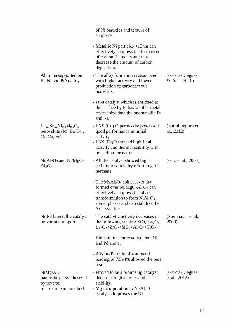
Table 2.2: Summary of previous research and its significant result
Catalyst Significant results Reference
Nickel catalysts
supported on
CaO.2Al2O3
- Nickel catalyst with different
nickel loadings supported on
nanocrystalline calcium aluminate
employed in methane reforming,
show high activity and stability due
to presence of CaO in the support
which declined coke deposition in
catalysts.
(Ranjbar &
Rezaei, 2012b)
10
- 7% N loading show higher activity
and lower coke formation.
Co and Ni supported on
CeO2 as selective
bimetallic catalyst
- Bimetallic Co-Ni/CeO2 catalysts is
more active, selective and
thermally stable for the synthesis
gas production due to intrinsic
property of Co-Ni alloy.
(Luisetto et al.,
2012)
Ni/perovskite catalysts
prepared by solid phase
crystallization method
- The catalysts, spc-Ni/MgTiO3, spc-
Ni/CaTiO3, spc-Ni/Ca0.8Sr0.2TiO3,
spc-Ni/SrTiO3, spc-Ni/Ca0.8Ba0.2
were obtained in situ by the spc
method.
- Ni/Ca0.8Sr0.2TiO3 and Ni/BaTiO3
catalysts showed high activity as
well as high sustainability among
the catalysts tested.
(Hayakawa et al.,
1999)
Nickel catalyst supported
on (Al2O3, CeO2, La2O3,
ZrO2)
- The catalyst supported on ZrO2
showed the highest stable activity.
- The catalyst supported on CeO2 has
a relatively good activity but
showed sign of deactivation after
certain reaction time.
(Barroso-Quiroga
& Castro-Luna,
2010)
Strontium carbonate
supported cobalt catalyst
- Co-SrCO3 showed high tolerance
to oxidative atmosphere under
1MPa, 1023K.
(Omata et al.,
2004)
Ni/BaTiO3-Al2O3 - Ni/BaTiO3 showed poor stability
and severe coke formation.
- Ni/BaTiO3-Al2O3 has a higher
dispersion of nickel and
Ni32.4%/BaTiO3-Al2O3 exhibited a
high catalytic activity and excellent
stability for lower temperature in
dry reforming.
(Li et al., 2012)
Y2O3-ZrO2 supported on
nickel catalyst
- The formation of surface oxygen
vacancies in Y2O3-ZrO2 system
increase in the interaction between
nickel species and the surface
oxygen vacancies, thus improve the
methane conversion.
(Bellido & Assaf,
2009)
11
- The best performance achieved by
5Ni8YZ catalyst, with load of
8%mol Y2O3.
Barium and lanthanum
incorporation to
supported Pt and Rh on
α-Al2O3
- La incorporation induces a rate
enhancement in conversion of
methane to synthesis gas
(Ghelamallah &
Granger, 2012)
Nickel catalyst supported
on nanocrystalline
calcium aluminates with
different CaO/Al2O3 ratio
- Nanocrystalline calcium oxides
with different CaO/Al2O3 ratio are
suitable as the support of catalysis
in dry reforming process.
- Calcium aluminate due to its
relatively high basicity and small
particle size show high activity and
stability.
- CaO in the catalyst can reduce the
carbon formation during the
reaction.
- CH4 and CO2 conversion decreased
with increasing CaO/Al2O3 ratio,
this may due to fact that higher
ratio have lower surface area and
thus lower nickel dispersion in
catalysts.
(Ranjbar &
Rezaei, 2012a)
CaO promoted Ni/ZrO2 - CaO-ZrO2 solid solution support
suffers the influence of surface
oxygen vacancies on their
reduction behaviour.
- The best performance archieved by
5Ni8CZ with CaO 8 mol% in
support.
- The addition of alkaline earth
oxides, CaO to oxide supports for
Ni catalysts improve reforming
reactions by preventing carbon
deposition on the active sites.
(Bellido et al.,
2009)
Potassium promoted
Ni/Al2O3
- The addition of low amount of
potassium (0.2%K2O) increase
catalytic activity (over 63%
methane conversion) and low coke
deposition (< 30mgC/g.cat)
(Juan-Juan et al.,
2006)
Ni/La2O3/Al2O3 - The species and amount deposited
on the catalysts depended on size
(Xu et al., 2009)
12
of Ni particles and texture of
supporter.
- Metallic Ni particles <15nm can
effectively suppress the formation
of carbon filaments and thus
decrease the amount of carbon
deposition.
Alumina supported on
Pt, Ni and PtNi alloy
- The alloy formation is associated
with higher activity and lower
production of carbonaceous
materials.
- PtNi catalyst which is enriched at
the surface by Pt has smaller metal
crystal size than the onometallic Pt
and Ni.
(García-Diéguez
& Pieta, 2010)
La0.8Sr0.2Ni0.8M0.2O3
perovskite (M=Bi, Co ,
Cr, Cu, Fe)
- LNS (Cu) O perovskite possessed
good performance in initial
activity.
- LNS (Fe)O showed high final
activity and thermal stability with
no carbon formation
(Sutthiumporn et
al., 2012)
Ni/Al2O3 and Ni/MgO-
Al2O3
- All the catalyst showed high
activity towards dry reforming of
methane.
- The MgAl2O4 spinel layer that
formed over Ni/MgO-Al2O3 can
effectively suppress the phase
transformation to form NiAl2O4
spinel phases and can stabilize the
Ni crystallite
(Guo et al., 2004)
Ni-Pd bimetallic catalyst
on various support
- The catalytic activity decreases in
the following ranking ZrO2-La2O3.
La2O3>ZrO2>SiO2>Al2O3>TiO2
- Bimetallic is more active than Ni
and Pd alone.
- A Ni to Pd ratio of 4 at metal
loading of 7.5wt% showed the best
result.
(Steinhauer et al.,
2009)
NiMg/Al2O3
nanocatalyst synthesized
by reverse
microemulsion method
- Proved to be a promising catalyst
due to its high activity and
stability.
- Mg incorporation to Ni/Al2O3
catalysts improves the Ni
(García-Diéguez
et al., 2012)
13
dispersion by the surface
rearrangement and further reduces
the carbon formation.
SBA-15 supported nickel
promoted by
Ce0.75Zr0.25O2
- The CZ addition enhances the
Ni/SBA-15 catalytic behaviour
toward methane conversion
between 600°C and 630°C.
- It enhances the catalysts stability
(Albarazi et al.,
2013)
NiCeO2ZrO2MgAl2O4
with various composition
- Best dry reforming performances
were achieved with catalyst
compositions having low Ni (2 wt
%), ZrO2 (<1 wt %) and high CeO2
(>3 wt %) content.
(Corthals et al.,
2011)
Ni-Ce supported on a
modified mineral clay
with Al and PVA
(polyvinylic alcohol)
- The catalysts present high CO2 and
CH4 conversions with high
performances to H2 and H2/CO
ratios between 0.6 and 1.2
(Daza et al., 2009)
Ni0.1Mg0.9O
nanocrystalline powder
- Highly stable activity for the
reforming of methane with carbon
dioxide.
- Surfactant addition has a
significant effect on the textural
properties of Ni0.1Mg0.9O powders
and led to obtain a powder with
high surface area.
(Zanganeh et al.,
2013)
Dealuminated FAU type
Y and BEA zeolites
supports on Ni and Pt (1
or 0.5 wt %)
- Dealumination by steaming of
FAU type Y and BEA zeolites
formed mesopores causing the
metals to highly disperse during
impregnation.
- The catalytic performance in the
reforming showed that Ni-
containing monometallic samples
were inactive in the reaction due to
the large amount of flamentous
amorphous carbon deposited on
these solids.
(Pinheiro et al.,
2009)
14
2.6 Catalyst Preparation
Solid catalysts are highly sophisticated products derived from chemicals by means of
several different procedures. The catalytic properties of heterogeneous catalysts are
strongly affected by every step of the preparation together with the quality of the raw
materials. The choice of a laboratory method for preparing a given catalyst depends on
the physical and chemical characteristics desired in the final composition (Perego and
Villa, 1997).
The criteria for a good catalyst depend on the activity, selectivity, thermal and mechanical
properties, stability, morphology and cost (Rojas, 2013). The preparation of supported
catalysts aims to attach the active phase onto the support. Impregnation, co-precipitation,
homogeneous deposition, deposition of surfactant (organic agent) stabilized metal
particles are some method in preparation of catalyst (Rojas, 2013). The general steps in
preparation of catalysts start with mixing solution/solids, then equilibration or aging.
After that solid liquid separation and drying. Calcination is carried out to decompose the
metal precursor with formation of oxide and removal of gaseous products such as water
and carbon dioxide (Perego and Villa, 1997). Finally, before the catalyst is ready to be
used in any reaction, it must be activated.
Impregnation is the simplest method to prepare supported catalysts. Solution containing
the metal precursor is contacted with porous support. For dry impregnation (pore volume
impregnation), the exact amount of liquid to fill the pore volume of the support is used;
as for wet impregnation, the amount of liquid depends on the solubility of the metal
precursor. The electrostatic forces control the adsorption mechanism of the porous
support (Rojas, 2013).
Previous studies show how calcium aluminate supported catalysts was prepared by using
excess-solution impregnation method using prepared support and different concentrations
of aqueous solutions of Ni (NO3)2.6H2O to obtain 5, 7, 10 and 15 wt. % nickel content.
After impregnation, the samples were dried at 80°C for 24 h and calcined at 600°C for 4
h (Ranjbar & Rezaei, 2012b).
Another study shows Ni-Ce catalysts supported on modified mineral clay were prepared
by the incipient co-impregnating method using an exact quantity of Ni (NO3)2.6H2O (10%