Synthesis and display of dynamic holographic 3D scenes with real-world objects
Melania Paturzo,1* Pasquale Memmolo,
1,2 Andrea Finizio,
1 Risto Näsänen,
3 Thomas J.
Naughton3,4
and Pietro Ferraro1
1CNR Istituto Nazionale di Ottica – Sezione di Napoli Via Campi Flegrei, 34 80078 Pozzuoli (Napoli) Italy
2DIET, Università di Napoli “Federico II”, Via Claudio 21, 80125 Napoli, Italy 3University of Oulu, Oulu Southern Institute, Vierimaantie 5, 84100 Ylivieska, Finland 4Department of Computer Science, National University of Ireland Maynooth, Ireland
Abstract: A 3D scene is synthesized combining multiple optically recorded digital holograms of different objects. The novel idea consists of compositing moving 3D objects in a dynamic 3D scene using a process that is analogous to stop-motion video. However in this case the movie has the exciting attribute that it can be displayed and observed in 3D. We show that 3D dynamic scenes can be projected as an alternative to complicated and heavy computations needed to generate realistic-looking computer generated holograms. The key tool for creating the dynamic action is based on a new concept that consists of a spatial, adaptive transformation of digital holograms of real-world objects allowing full control in the manipulation of the object’s position and size in a 3D volume with very high depth-of-focus. A pilot experiment to evaluate how viewers perceive depth in a conventional single-view display of the dynamic 3D scene has been performed.
OCIS codes: (090.1995) Digital holography; (090.2870) Holographic display; (090.4220) Multiplex holography; (100.2000) Digital image processing.
References and links
1. D. Gabor, “A new microscopic principle,” Nature 161(4098), 777–778 (1948). 2. J. W. Goodman, and R. W. Lawrence, “Digital image formation from electronically detected holograms,” Appl.
Phys. Lett. 11(3), 77–79 (1967). 3. C. D. Müller, A. Falcou, N. Reckefuss, M. Rojahn, V. Wiederhirn, P. Rudati, H. Frohne, O. Nuyken, H. Becker,
and K. Meerholz, “Multi-colour organic light-emitting displays by solution processing,” Nature 421(6925), 829–833 (2003).
4. B. L. Volodin, B. Kippelen, K. Meerholz, B. Javidi, and N. Peyghambarian, “A polymeric optical pattern-recognition system for security verification,” Nature 383(6595), 58–60 (1996).
5. T. Kreis, Handbook of Holographic Interferometry: Optical and Digital Methods (Wiley-VCH, 2005). 6. M. R. Chatterjee, and S. Chen, Digital Holography and Three-Dimensional Display: Principles and Applications
(ed. Poon, T. Springer, New York, 2006), Chap. 13. 7. S. Fukushima, T. Kurokawa, and M. Ohno, “Real-time hologram construction and reconstruction using a high-
resolution spatial light-modulator,” Appl. Phys. Lett. 58(8), 787–789 (1991). 8. S. A. Benton, and V. M. Bove, Jr, Holographic Imaging (Wiley Inter-Science 2008). 9. H. M. Ozaktas, and L. Onural, eds., Three-Dimensional Television Capture, Transmission, Display Series:
Signals and Communication Technology (Springer, 2008) 10. N. T. Shaked, B. Katz, and J. Rosen, “Review of three-dimensional holographic imaging by multiple-viewpoint-
projection based methods,” Appl. Opt. 48(34), H120–H136 (2009). 11. N. A. Dodgson, “Autostereoscopic 3D displays,” Computer 38(8), 31–36 (2005). 12. K. Choi, J. Kim, Y. Lim, and B. Lee, “Full parallax viewing-angle enhanced computer-generated holographic 3D
display system using integral lens array,” Opt. Express 13(26), 10494–10502 (2005). 13. D. Miyazaki, K. Shiba, K. Sotsuka, and K. Matsushita, “Volumetric display system based on three-dimensional
scanning of inclined optical image,” Opt. Express 14(26), 12760–12769 (2006). 14. S. A. Benton, Selected Papers on Three-Dimensional Displays (SPIE Optical Engineering Press, Bellingham,
Washington, 2001) 15. Y. Frauel, T. J. Naughton, O. Matoba, E. Tajahuerce, and B. Javidi, “Three-dimensional imaging and processing
using computational holographic imaging,” in Proceedings of the IEEE, 94, 636–653 (2006).
#124464 - $15.00 USD Received 19 Feb 2010; revised 26 Mar 2010; accepted 28 Mar 2010; published 13 Apr 2010(C) 2010 OSA 26 April 2010 / Vol. 18, No. 9 / OPTICS EXPRESS 8806
16. L. A. Lessard, and H. I. Bjelkhagen, eds., Practical Holography XXI: Materials and Applications (Special Issue) Proc. SPIE 6488, (2007).
17. P. Ferraro, M. Paturzo, P. Memmolo, and A. Finizio, “Controlling depth of focus in 3D image reconstructions by flexible and adaptive deformation of digital holograms,” Opt. Lett. 34(18), 2787–2789 (2009).
18. M. Paturzo, and P. Ferraro, “Creating an extended focus image of a tilted object in Fourier digital holography,” Opt. Express 17(22), 20546–20552 (2009).
19. G. Tricoles, “Computer generated holograms: an historical review,” Appl. Opt. 26(20), 4351–4357 (1987). 20. P. S. Hilaire, S. A. Benton, and M. Lucente, “Synthetic aperture holography: a novel approach to three
dimensional displays,” J. Opt. Soc. Am. A 9(11), 1969–1978 (1992). 21. C. W. Slinger, C. D. Cameron, S. D. Coomber, R. J. Miller, D. A. Payne, A. P. Smith, M. G. Smith, M. Stanley,
and P. J. Watson, “Recent developments in computer-generated holography: toward a practical electroholography system for interactive 3D visualization,” Proc. SPIE 5290, 27–41 (2004).
22. M. L. Huebschman, B. Munjuluri, and H. R. Garner, “Dynamic holographic 3-D image projection,” Opt. Express 11(5), 437–445 (2003).
23. S. Ş. Tay, P.-A. Blanche, R. Voorakaranam, A. V. Tunç, W. Lin, S. Rokutanda, T. Gu, D. Flores, P. Wang, G. Li, P. St Hilaire, J. Thomas, R. A. Norwood, M. Yamamoto, and N. Peyghambarian, “An updatable holographic three-dimensional display,” Nature 451(7179), 694–698 (2008).
24. Y. Ichihashi, N. Masuda, M. Tsuge, H. Nakayama, A. Shiraki, T. Shimobaba, and T. Ito, “One-unit system to reconstruct a 3-D movie at a video-rate via electroholography,” Opt. Express 17(22), 19691–19697 (2009).
25. B. Munjuluri, M. L. Huebschman, and H. R. Garner, “Rapid hologram updates for real-time volumetric information displays,” Appl. Opt. 44(24), 5076–5085 (2005).
26. L. Ahrenberg, P. Benzie, M. Magnor, and J. Watson, “Computer generated holograms from three dimensional meshes using an analytic light transport model,” Appl. Opt. 47(10), 1567–1574 (2008).
27. C. P. McElhinney, B. M. Hennelly, and T. J. Naughton, “Extended focused imaging for digital holograms of macroscopic three-dimensional objects,” Appl. Opt. 47(19), D71–D79 (2008).
28. I. P. Howard and B. J. Rogers Seeing in depth, vol. 2 (I Porteous, Toronto, 2002).
1. Introduction
Since its discovery by Dennis Gabor, holography has encouraged the expectation for a spectacular 3D imaging and display system [1,2]. Classical holography, based on photosensitive films and plates had its main limitation in its chemical processing and single-shot procedure. Alternate recording media such as photorefractive crystals and polymers, thermoplastic, photopolymers film make holographic video possible [3,4].
The arrival of solid state sensors in the 1970s opened the new era of digital holography (DH). Nevertheless, despite the tremendous technological progress of solid state sensors, they have not yet surpassed the incredible spatial resolution (more then 5000 lines/mm) of classical recording materials. However, the expectation for a spectacular dynamic 3D display is now to be entrusted to DH. Holograms are digitally recorded, directly and very fast, by CCD or CMOS matrix sensors in visible or even in IR spectra. The reconstruction can be either performed numerically for a 2D screen or for display in 3D by a SLM (spatial light modulator) [5–7].
Although the expectations for an efficient and high quality 3D system have not been matched yet by technology, there is a huge industrial and economic interest in, and fascination with, such a natural way of perceiving an artificial 3D world. The synthesis of dynamic 3D scenes can be useful in many fields such as for training and simulation of real-world scenarios (surgery training, 3D object design and visualisation, object recognition for robotics/military purposes, and so on). Of course, the enormous application for entertainment (for example, video-games, virtual reality, 3D video) cannot be underestimated [8,9].
Considerable progress has been made in recent years in 3D imaging and display along different directions [10–13], even if holography remains the definitive and most challenging approach [14–18]. In fact, while all other techniques are 3D only under a host of conditions, holography and its wavefront reconstruction family is the only true 3D imaging and display technique. Holographic displays have the unique advantage of representing all possible visual depth cues, autostereoscopically (without glasses), with both vertical and horizontal parallax, giving an appropriate medium for unlimited simultaneous viewers at arbitrary viewing positions, and without the potentially nausea-inducing accommodation-vergence rivalry inherent in modern stereoscopic 3D cinema.
Most of the impressive achievements in holographic 3D display that have been reported were obtained through the realization of computer generated holograms (CGHs) [19–23].
#124464 - $15.00 USD Received 19 Feb 2010; revised 26 Mar 2010; accepted 28 Mar 2010; published 13 Apr 2010(C) 2010 OSA 26 April 2010 / Vol. 18, No. 9 / OPTICS EXPRESS 8807
CGHs have been extensively studied because they are an extremely flexible precursor to the more difficult task of directly obtaining a digital hologram by optically recording a 3D scene. With CGHs it is possible to synthesize holograms not only of single objects but of full scenes with multiple dynamic objects. However it is an extremely difficult task due to the huge computation time and often the results are usually of poor quality in terms of image resolution, even if recently some progresses have been done in optimizing algorithms for generating CGHs [24–26].
Most importantly, CGHs by definition contain only computer-generated information, and come up short in a realistic representation of the world around us in the same way that in modern cinema computer-generated cartoons fail to capture the realism and emotion of life-action films.
Conversely, if we consider optical holograms, one of the main and as yet unresolved problems in recording a dynamic scene of real-objects by a laser is strictly connected with the intrinsic properties of such a light source. The paradox in holography is that while the high directionality and coherence of the light source satisfies the mandatory requirements to record a hologram, these properties affect severely the recording process. In fact, the hologram’s quality is strongly dependent on the object’s position relative to the recording camera because of such properties. Those difficulties are common to all types of holography independent of the recording medium and technique.
This can be explained as follows. For a particular object size and camera pixel size, there is a minimum distance at which the object can be correctly sampled. Surface orientation and texture of the object can also cause problems in recording digital holograms. Depending on the location of the light source and the recording camera, (i.e. the illumination and observation directions, respectively) the scattered light from the object can have such a variation that for each position it must be necessary to adjust intensity of the illumination object beam, change the direction of illumination, and adjust the exposure time. In fact it is straightforward to understand that if the object’s position changes in the 3D volume, in front of the recording medium, the illuminating laser light strikes the object from different directions for each position. The scattered spectrum (amplitude and phase) is also dependent on the illumination direction, affecting the amount of light that reaches the camera aperture. In addition, the high directionality of laser light produces sharp shadows that can hinder the visibility, and that can change with the object's position. Moreover, speckle size and intensity recorded by the camera, which can affect quality of reconstructed objects, are a function of the distance between the object and the recording medium.
Considering, for example, holograms of two identical objects recorded with a single laser beam in a 3D imaged volume, and set at two different distances from the camera, gives as the result in the reconstruction process (either numerical or optical) two images that can have completely different quality because of the inverse-square law and because of speckles. Consequently, it is important to underline that the optimization of all recording parameters in holography (laser, optical configuration, object surface shape and texture, etc.) is impractical if the aim is to obtain reconstructed images of same quality for objects at different distances. While in photography, or any other imaging technique with white light, there is also a dependence on the light conditions and optical configuration, it is quite easy to optimize illumination conditions due to the incoherent character of such light.
More severe is the limit in terms of field-of-view. It is well known the pixel size and numerical aperture (NA) of the imaging sensor limits the field of view, which is due to the cut-off limit in sampling the spatial frequencies of the hologram (the interferometric fringes) [5]. The above constraint has practical drawbacks that limit the maximum extension of an object or even the range in which, for a fixed optical configuration, an object can be displaced laterally in the 3D scene (the volume in front of the camera) during the recording process.
The aforementioned problems imply that, generally speaking, holographic recording of a dynamic 3D scene, in which for example a single object is moved in an ample volume, requires an adaptive optical configuration that is optimized for each position of the object. In
#124464 - $15.00 USD Received 19 Feb 2010; revised 26 Mar 2010; accepted 28 Mar 2010; published 13 Apr 2010(C) 2010 OSA 26 April 2010 / Vol. 18, No. 9 / OPTICS EXPRESS 8808
practice, for such an adaptive system, dynamically satisfying illumination, speckle reduction, and sampling conditions would not be feasible.
In order to overcome each of these difficulties, we propose here an original method that consists of recording each real-world object individually under favourable conditions, and then building-up a dynamic synthetic 3D scene with a process that is analogous to stop-motion video. However, in our case the movie has all the advantageous attributes associated with holographic display, such as representing all possible visual depth cues without incompatibility. The method is possible due to an innovative way in which we process the digital holograms that has never been implemented before.
2. Methods
To create a dynamic 3D scene using only one hologram, we consider a digital hologram of a single object recorded at distance d. The reconstruction of the object in focus is obtained numerically at distance d from the hologram plane by computing the well known diffraction Fresnel propagation integral, given by
( )22
2 2
( )1
2 21( , ) ( , ) ( , )
yxikd
d db x y h r e d d
i d
ηξ
ξ η ξ η ξ ηλ
−− + + = ∫∫ (1)
where h(x,y) and r(x,y) are the hologram and reference beam respectively. Usually r(x,y) = 1, which means it is a plane wavefront. If an affine geometric transformation is applied to the original recorded hologram, consisting of a simple stretching and described by
[ ] [ ]' ' 1 Tξ η ξ η= through the operator
0
0
0 0
a
T a
=
, we obtain the transformed hologram
( ) ( )', ' ,h h a aξ η ξ η= . Consequently, the propagation integral changes to
( ) ( )( ) ( )2 22 2
2 22 21
, , ,
ik x ik y
ikd d dB x y d e h e e d di d
α ξ α η
α ααξ αη ξ ηλ
− −
= =∫∫
( )( ) ( )
( )2 2
' ' ' '
' ' ' ' ' '2 22 2
1 1, , ,
ik x ik y
ikd D De h e e d d b x y Di d
ξ η
ξ η ξ ηα λ α
− −
= =∫∫ (2)
with 2/D d α= and ' /x x α= , ' /y y α= where α is the elongation factor. Such simple
stretching applied to the hologram has a very interesting impact on the numerical or even optical reconstructions. In fact from Eq. (2) it is clear that when reconstructing the new
hologram the in-focus distance becomes 2/D d α= . Therefore, through subsequent
reconstruction of the same hologram, stretched with a variable elongation factor α, it is possible to create a dynamic 3D scene with the object moving along the z axis. Moreover, a movement of the object in x,y directions can also be added by a simple shift in the reconstruction plane. To synthesize a dynamic 3D scene with more than one object, we construct each frame of the movie combining various digital holograms according to the following procedure:
1) Each hologram is reconstructed in a plane in which it is largely in focus.
2) To filter out the off-axis conjugated order a spatial mask is applied to the complex field in the image plane.
3) The position of each object in the x-y plane is changed by a simple shift in order to avoid superimposition of different objects in the combined image.
#124464 - $15.00 USD Received 19 Feb 2010; revised 26 Mar 2010; accepted 28 Mar 2010; published 13 Apr 2010(C) 2010 OSA 26 April 2010 / Vol. 18, No. 9 / OPTICS EXPRESS 8809
4) The complex wavefield is propagated back to the hologram plane.
5) Each hologram is stretched according to the desired change of the in-focus distance, that is the object position along the z-axis.
6) The complex-valued holograms are added together to yield a multiplexed hologram.
7) The multiplexed hologram is reconstructed at a fixed distance to obtain the multi-object scene.
3. Experimental results
3.1 Numerical reconstruction of 3D scene
For the experimental validation of our method, we consider a digital hologram of a single object, a puppet of the Neapolitan tradition, “Pulcinella,” and an astronaut, recorded with an optimized optical configuration that optimizes recording parameters such as object-to-CCD distance and illumination intensity for a high quality hologram reconstruction. The holograms are acquired by means of a Mach-Zehnder interferometer in off-axis configuration with a plane reference wave. The laser source used is a DPSS laser emitting at 0.532 µm, while the distance between the objects and the CCD is approximately 56 cm.
Fig. 1. (a) Scheme of the movement (back-and-forth along the z-axis) performed by a single object through subsequent deformations of the same hologram; (b) numerical reconstruction of the hologram after its stretching with a deformation parameter of 0.8, 1, 1.2, respectively (from left to right); in the upper row the distance of reconstruction is fixed at the recording distance, while in the lower row it is changed to obtain in-focus images.
If we transform the hologram as in Eq. (2), the object is obtained in focus at a distance different to the original recording distance and with different lateral magnification. Based on this simple principle we can play with a digital hologram by creating a 3D scene in which a single object is moved back-and-forth as depicted in Fig. 1(a). Since the hologram can be numerically transformed to change the distance at which it will appear in focus in the reconstruction process, an observer will see a 3D scene in both the numerical reconstruction and the optical reconstruction by a SLM device.
With this aim, the same digital hologram is successively reconstructed with different elongation factors α. Figure 1(b) shows the numerical reconstruction of Pulcinella’s hologram stretched with elongation factors α of 0.8, 1 and 1.2, respectively. According to the formulas
#124464 - $15.00 USD Received 19 Feb 2010; revised 26 Mar 2010; accepted 28 Mar 2010; published 13 Apr 2010(C) 2010 OSA 26 April 2010 / Vol. 18, No. 9 / OPTICS EXPRESS 8810
of Section 2, we can estimate that the depth of focus changes by about 48 cm. The numerical reconstructions in the upper row of Fig. 1(b) were performed at a single reconstruction distance for all deformed holograms. The lower row of Fig. 1(b) shows the numerical reconstructions of the deformed holograms where the reconstruction distance is changed to maintain Pulcinella in focus. It is clear that hologram stretching is equivalent to a change in the reconstruction distance and in the image lateral magnification.
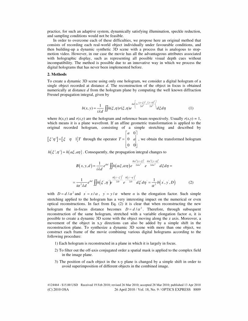
Fig. 2. Holograms acquired during the object rotation: Numerical reconstructions of four different digital holograms recorded while the object rotates by 360° around its vertical axis from a fixed position (Media 1).
The results of Fig. 1(b) demonstrate that the apparent position in the holographic reconstruction of a real object can be changed independently of the original recorded distance. Dynamic and more complex 3D scenes can be synthetically constructed using different holograms. In our example, the procedure is based on recording several digital holograms of individual objects each of which rotates about its vertical axis but in a fixed position.
Figure 2 shows four numerical holographic reconstructions of Pulcinella from different angles. (The corresponding movie shows the full 360° sequence.) The recording process is performed with an optimized optical configuration that admits a high quality hologram. Each recorded hologram is geometrical transformed, by numerical stretching and shifting in the x-y plane, to create a dynamic 3D scene in which Pulcinella travels backwards and forwards in the 3D volume while performing a “pirouette.”
3.2 Optical display of a 3D scene
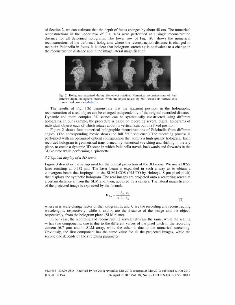
Figure 3 describes the set-up used for the optical projection of the 3D scene. We use a DPSS laser emitting at 0.532 µm. The laser beam is expanded in such a way as to obtain a convergent beam that impinges on the SLM-LCOS (PLUTO-by Holoeye, 8 µm pixel pitch) that displays the synthetic hologram. The real images are projected onto a scattering screen at a certain distance zi from the SLM and, then, acquired by a camera. The lateral magnification of the projected image is expressed by the formula
o
i
r
clat
z
z
mM
λλ1
= (3)
where m is scale-change factor of the hologram, λr and λc are the recording and reconstructing wavelengths, respectively, while zi and zo are the distance of the image and the object, respectively, from the hologram plane (SLM plane).
In our case, the recording and reconstructing wavelengths are the same, while the scaling m has two components: one is due to the different values of the pixel pitch in the recording camera (6.7 µm) and in SLM array, while the other is due to the numerical stretching. Obviously, the first component has the same value for all the projected images, while the second one depends on the stretching parameter.
#124464 - $15.00 USD Received 19 Feb 2010; revised 26 Mar 2010; accepted 28 Mar 2010; published 13 Apr 2010(C) 2010 OSA 26 April 2010 / Vol. 18, No. 9 / OPTICS EXPRESS 8811
Fig. 3. Set-up used for the optical projection of the 3D scene; MO: microscope objective, SF: spatial filter, L: lens, BS: beam splitter, SLM: spatial light modulator, M: mirror.
To estimate the magnification we also need to calculate the distance at which the reconstructed image appears in focus. The position of the image is obtained from the formula
−±=
rr
c
ci zzmzz
11111
02 λλ
(4)
where zc and zr are the radii of curvature of the reference wave in the recording and reconstruction process, respectively. We used a plane reference wave in the recording process
(r
z = ∞ ) and a convergent wave in the reconstruction one. Consequently, the distance of the
reconstructed images from the SLM increases with stretching parameter, while their size decreases.
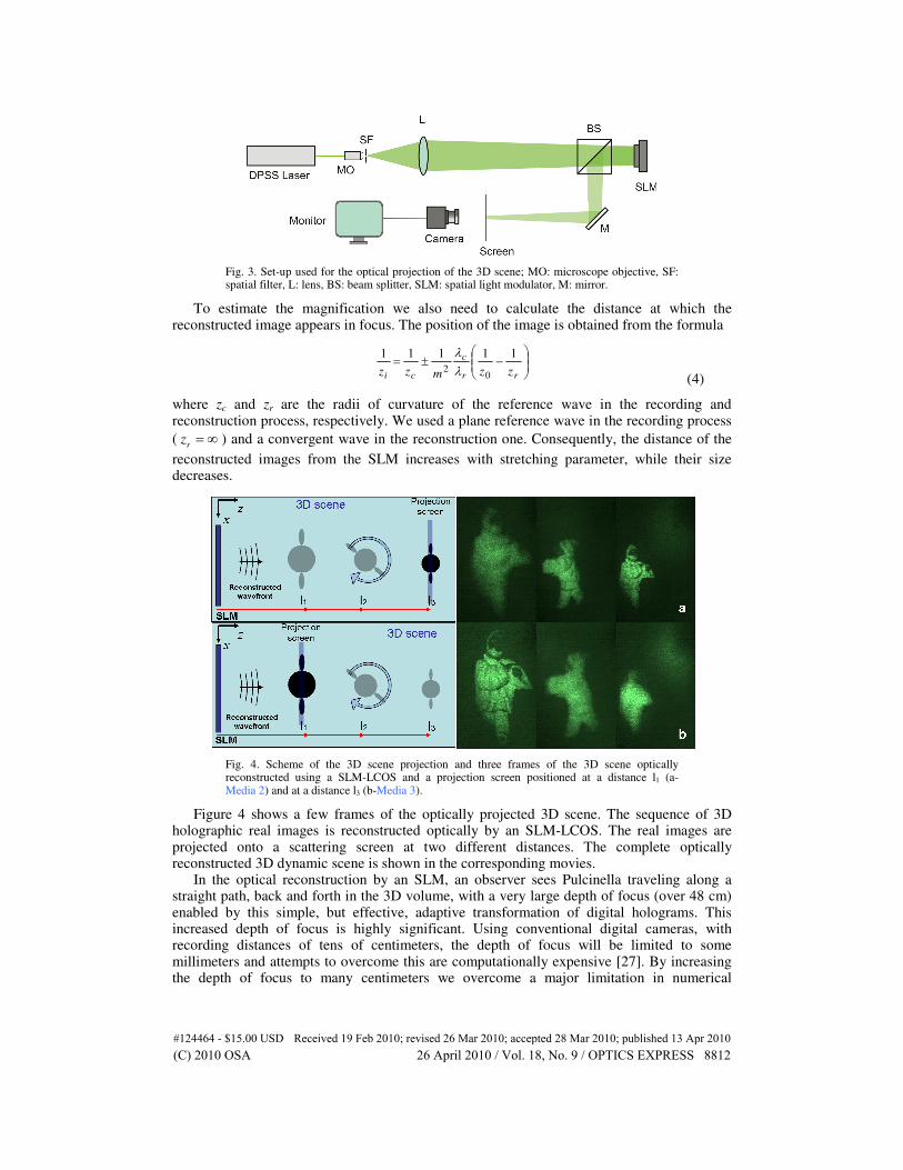
Fig. 4. Scheme of the 3D scene projection and three frames of the 3D scene optically reconstructed using a SLM-LCOS and a projection screen positioned at a distance l1 (a- Media 2) and at a distance l3 (b-Media 3).
Figure 4 shows a few frames of the optically projected 3D scene. The sequence of 3D holographic real images is reconstructed optically by an SLM-LCOS. The real images are projected onto a scattering screen at two different distances. The complete optically reconstructed 3D dynamic scene is shown in the corresponding movies.
In the optical reconstruction by an SLM, an observer sees Pulcinella traveling along a straight path, back and forth in the 3D volume, with a very large depth of focus (over 48 cm) enabled by this simple, but effective, adaptive transformation of digital holograms. This increased depth of focus is highly significant. Using conventional digital cameras, with recording distances of tens of centimeters, the depth of focus will be limited to some millimeters and attempts to overcome this are computationally expensive [27]. By increasing the depth of focus to many centimeters we overcome a major limitation in numerical
#124464 - $15.00 USD Received 19 Feb 2010; revised 26 Mar 2010; accepted 28 Mar 2010; published 13 Apr 2010(C) 2010 OSA 26 April 2010 / Vol. 18, No. 9 / OPTICS EXPRESS 8812
reconstruction of digital holograms. The limited depth of focus is also a problem in optical reconstruction of real images from digital holograms.
The advantage of this synthetic procedure is that a more complex 3D scene can be displayed using holograms that have been recorded in ideal conditions and hence with the same high quality. The geometric transformation can be flexibly adapted to manipulate the object’s position and size in 3D and within a very large depth of field dispensing with the recording of holograms at different distances from the camera. We claim that in our case the puppet can be recorded with different postures to get 3D scenes containing whatever animated action is desired (walking, speaking, moving arms, etc.).
In order to move the object in 3D it is not necessary to record holograms of the object at different positions in respect to the camera, but, instead, adaptively transform a single digital hologram. We could say that each stored hologram is a single template to build–up the 3D scene with high flexibility. A basic archive of “postures” (a sort of database of digital holograms) of one or more puppets, recorded in optimal conditions at a fixed distance and position in respect to the CCD camera, can allow one to construct 3D dynamic scenes with no limitations in arrangement or dynamic action.
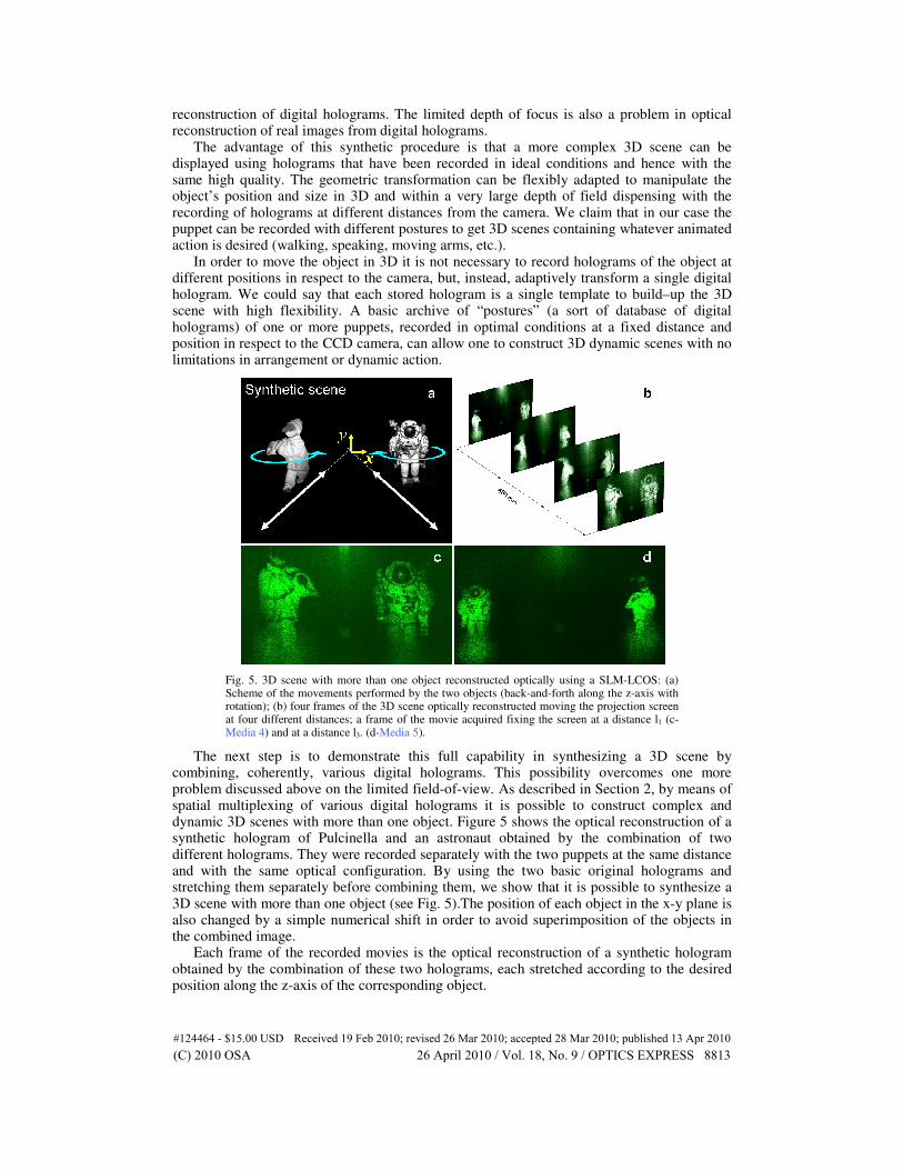
Fig. 5. 3D scene with more than one object reconstructed optically using a SLM-LCOS: (a) Scheme of the movements performed by the two objects (back-and-forth along the z-axis with rotation); (b) four frames of the 3D scene optically reconstructed moving the projection screen at four different distances; a frame of the movie acquired fixing the screen at a distance l1 (c-Media 4) and at a distance l3. (d-Media 5).
The next step is to demonstrate this full capability in synthesizing a 3D scene by combining, coherently, various digital holograms. This possibility overcomes one more problem discussed above on the limited field-of-view. As described in Section 2, by means of spatial multiplexing of various digital holograms it is possible to construct complex and dynamic 3D scenes with more than one object. Figure 5 shows the optical reconstruction of a synthetic hologram of Pulcinella and an astronaut obtained by the combination of two different holograms. They were recorded separately with the two puppets at the same distance and with the same optical configuration. By using the two basic original holograms and stretching them separately before combining them, we show that it is possible to synthesize a 3D scene with more than one object (see Fig. 5).The position of each object in the x-y plane is also changed by a simple numerical shift in order to avoid superimposition of the objects in the combined image.
Each frame of the recorded movies is the optical reconstruction of a synthetic hologram obtained by the combination of these two holograms, each stretched according to the desired position along the z-axis of the corresponding object.
#124464 - $15.00 USD Received 19 Feb 2010; revised 26 Mar 2010; accepted 28 Mar 2010; published 13 Apr 2010(C) 2010 OSA 26 April 2010 / Vol. 18, No. 9 / OPTICS EXPRESS 8813
Fig. 6. Numerical (a-Media 6) and optical (b-Media 7) reconstructions of a 3D scene with three objects.
Figure 6 and the corresponding movies show a 3D scene with three different objects. In Fig. 6(a) the numerical reconstruction of the 3D scene with two astronauts and a flag is performed, while in Fig. 6(b) the corresponding optical projection is shown. The in-focus distance changes to maintain the moving astronaut in focus.
3.3 Visual perception experiment
A pilot perception experiment was conducted to estimate the perceived depth in such a video sequence displayed on a conventional computer monitor. It is well known that motion parallax can produce strong depth perception [28]. Different cues can be used to determine depth, e.g., the retinal image of an approaching object increases in size while the retinal image of a departing object decreases in size. Also, the relative lateral movement of objects provides effective depth cues. Therefore, “Pulcinella on the moon” (Media 8), which contains both kinds of motion parallax information, can be expected to produce a clear perception of depth. The perception of depth in images is, however, in many cases underestimated [28]. So, we expect that the full extent of depth will not be perceived. The purpose of this pilot perception experiment is to demonstrate the existence of depth perception in the “Pulcinella on the moon” video sequence and to quantify it.
Fig. 7. Perception experiment: the observer looks at two windows. The one on the right shows the video clip (Media 8) while the other on the left shows a random-pattern stereoscopic image.
The non-stereo movie used in the perception experiment contains a sequence of Pulcinella and the astronaut dancing with axial movement along the viewing direction. The sequence was shown continuously looping back and forth as a single-view video clip displayed on a stereoscopic display. The task of the observer was to estimate the magnitude of Pulcinella’s movement in depth and to produce a perceptually equivalent stereoscopic distance in depth. Beside the window showing the non-stereo video clip there was another window showing a random-pattern stereoscopic image (see Fig. 7).
#124464 - $15.00 USD Received 19 Feb 2010; revised 26 Mar 2010; accepted 28 Mar 2010; published 13 Apr 2010(C) 2010 OSA 26 April 2010 / Vol. 18, No. 9 / OPTICS EXPRESS 8814
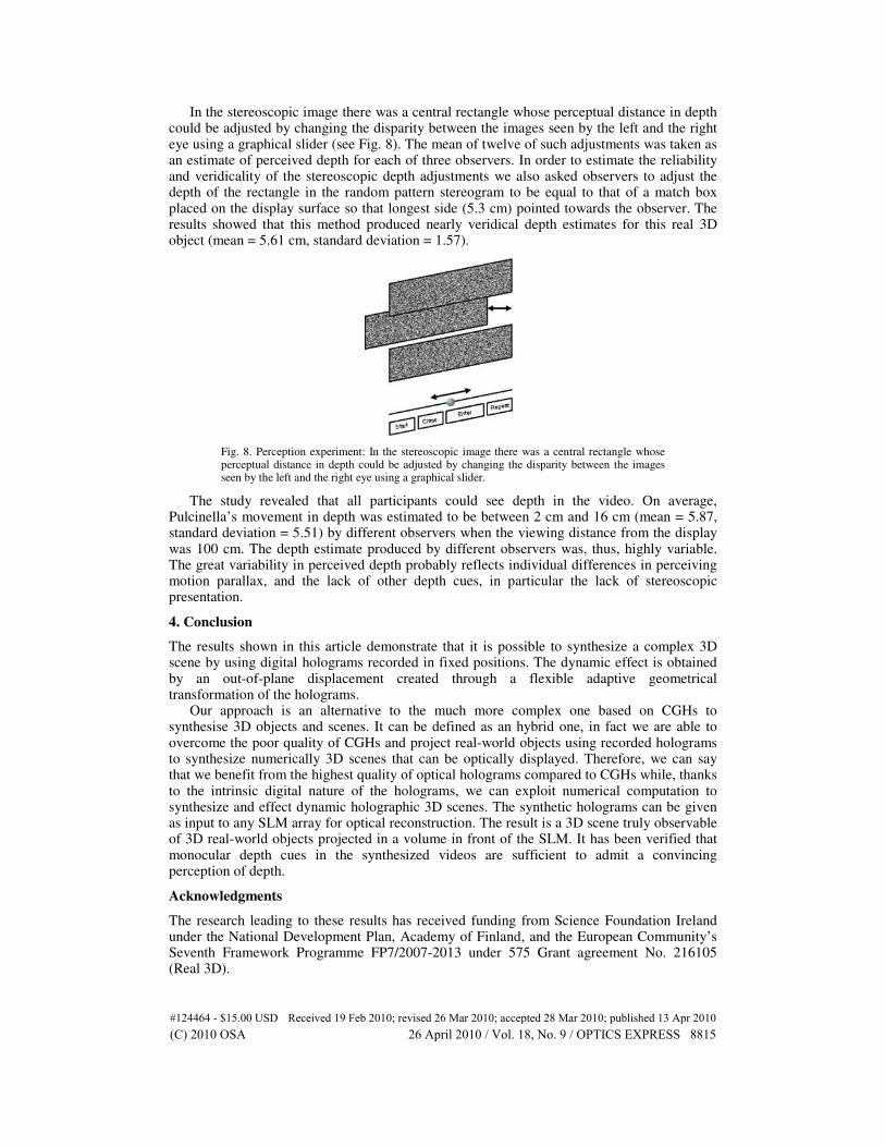
In the stereoscopic image there was a central rectangle whose perceptual distance in depth could be adjusted by changing the disparity between the images seen by the left and the right eye using a graphical slider (see Fig. 8). The mean of twelve of such adjustments was taken as an estimate of perceived depth for each of three observers. In order to estimate the reliability and veridicality of the stereoscopic depth adjustments we also asked observers to adjust the depth of the rectangle in the random pattern stereogram to be equal to that of a match box placed on the display surface so that longest side (5.3 cm) pointed towards the observer. The results showed that this method produced nearly veridical depth estimates for this real 3D object (mean = 5.61 cm, standard deviation = 1.57).
Fig. 8. Perception experiment: In the stereoscopic image there was a central rectangle whose perceptual distance in depth could be adjusted by changing the disparity between the images seen by the left and the right eye using a graphical slider.
The study revealed that all participants could see depth in the video. On average, Pulcinella’s movement in depth was estimated to be between 2 cm and 16 cm (mean = 5.87, standard deviation = 5.51) by different observers when the viewing distance from the display was 100 cm. The depth estimate produced by different observers was, thus, highly variable. The great variability in perceived depth probably reflects individual differences in perceiving motion parallax, and the lack of other depth cues, in particular the lack of stereoscopic presentation.
4. Conclusion
The results shown in this article demonstrate that it is possible to synthesize a complex 3D scene by using digital holograms recorded in fixed positions. The dynamic effect is obtained by an out-of-plane displacement created through a flexible adaptive geometrical transformation of the holograms.
Our approach is an alternative to the much more complex one based on CGHs to synthesise 3D objects and scenes. It can be defined as an hybrid one, in fact we are able to overcome the poor quality of CGHs and project real-world objects using recorded holograms to synthesize numerically 3D scenes that can be optically displayed. Therefore, we can say that we benefit from the highest quality of optical holograms compared to CGHs while, thanks to the intrinsic digital nature of the holograms, we can exploit numerical computation to synthesize and effect dynamic holographic 3D scenes. The synthetic holograms can be given as input to any SLM array for optical reconstruction. The result is a 3D scene truly observable of 3D real-world objects projected in a volume in front of the SLM. It has been verified that monocular depth cues in the synthesized videos are sufficient to admit a convincing perception of depth.
Acknowledgments
The research leading to these results has received funding from Science Foundation Ireland under the National Development Plan, Academy of Finland, and the European Community’s Seventh Framework Programme FP7/2007-2013 under 575 Grant agreement No. 216105 (Real 3D).
#124464 - $15.00 USD Received 19 Feb 2010; revised 26 Mar 2010; accepted 28 Mar 2010; published 13 Apr 2010(C) 2010 OSA 26 April 2010 / Vol. 18, No. 9 / OPTICS EXPRESS 8815